CN110386552B - Control device and method for controlling the movement of a load - Google Patents
Control device and method for controlling the movement of a load Download PDFInfo
- Publication number
- CN110386552B CN110386552B CN201910302694.7A CN201910302694A CN110386552B CN 110386552 B CN110386552 B CN 110386552B CN 201910302694 A CN201910302694 A CN 201910302694A CN 110386552 B CN110386552 B CN 110386552B
- Authority
- CN
- China
- Prior art keywords
- impulse response
- finite impulse
- filter
- response filter
- load
- Prior art date
- Legal status (The legal status is an assumption and is not a legal conclusion. Google has not performed a legal analysis and makes no representation as to the accuracy of the status listed.)
- Active
Links
Images


Classifications
-
- B—PERFORMING OPERATIONS; TRANSPORTING
- B66—HOISTING; LIFTING; HAULING
- B66C—CRANES; LOAD-ENGAGING ELEMENTS OR DEVICES FOR CRANES, CAPSTANS, WINCHES, OR TACKLES
- B66C13/00—Other constructional features or details
- B66C13/04—Auxiliary devices for controlling movements of suspended loads, or preventing cable slack
- B66C13/06—Auxiliary devices for controlling movements of suspended loads, or preventing cable slack for minimising or preventing longitudinal or transverse swinging of loads
- B66C13/063—Auxiliary devices for controlling movements of suspended loads, or preventing cable slack for minimising or preventing longitudinal or transverse swinging of loads electrical
-
- B—PERFORMING OPERATIONS; TRANSPORTING
- B66—HOISTING; LIFTING; HAULING
- B66C—CRANES; LOAD-ENGAGING ELEMENTS OR DEVICES FOR CRANES, CAPSTANS, WINCHES, OR TACKLES
- B66C13/00—Other constructional features or details
- B66C13/16—Applications of indicating, registering, or weighing devices
-
- B—PERFORMING OPERATIONS; TRANSPORTING
- B66—HOISTING; LIFTING; HAULING
- B66C—CRANES; LOAD-ENGAGING ELEMENTS OR DEVICES FOR CRANES, CAPSTANS, WINCHES, OR TACKLES
- B66C13/00—Other constructional features or details
- B66C13/18—Control systems or devices
- B66C13/48—Automatic control of crane drives for producing a single or repeated working cycle; Program control
Landscapes
- Engineering & Computer Science (AREA)
- Mechanical Engineering (AREA)
- Automation & Control Theory (AREA)
- Complex Calculations (AREA)
- Control And Safety Of Cranes (AREA)
Abstract
A control device for controlling the movement of a load carrying device load is disclosed. The load carrying device may for example be a crane and the load may be carried by a rope connected to a suspension point of the crane. The control device includes: an input interface for receiving an input signal indicative of a target speed of a load; an output interface for providing an output signal indicative of a reference velocity of the suspension point; and a processing system constituting a signal processing path for generating an output signal based on the input signal. The signal processing path comprises at least one finite impulse response filter for suppressing signal components whose frequency is the natural swing frequency of the load. Due to the finite impulse response, the time length of the settling effect and the tail effect caused by the filter is finite and deterministic.
Description
Technical Field
The present disclosure relates generally to motion control. More particularly, the present disclosure relates to a device and method for controlling the movement of a load that is non-rigidly connected to a suspension point whose speed and position are controllable. Further, the present disclosure relates to a system for handling a load. The system may be, for example, but not necessarily, a crane. Furthermore, the present disclosure relates to a computer program for controlling the movement of a load, wherein the load is non-rigidly connected to a suspension point whose speed and position are controllable.
Background
Undesirable oscillations are a problem affecting the performance of many mechanical systems in which the load is not rigidly connected to a suspension point whose speed and position are controlled. For example, when the suspension point moves, the load tends to oscillate. The tendency to oscillate may represent a risk of damaging the load and/or its surroundings and/or may reduce productivity by forcing the mechanical system to operate slowly. The mechanical system may for example be a crane comprising a crane carriage from which the load is suspended by suspension ropes. The crane operator provides speed commands via a control terminal connected to a control unit which controls the speed of the crane carriage. In crane applications of the above type, load swinging is a problem, especially in automatic cranes and in cranes where no technician controls the movement of the load.
It is a known fact that load swing can be reduced by increasing acceleration and deceleration ramp times and using long S-curve velocity shaping (i.e., limiting the time derivative of acceleration, i.e., limiting jerk). An inherent challenge with this approach is that the response and settling time may increase to unacceptable levels.
Another approach is to use a swing angle sensor in the motion control of the model-based load and utilize the output signal of the swing angle sensor. The model may be based on the equation of motion of classical newtonian dynamics. However, in many cases it is desirable to avoid instrumentation such as swing angle sensors that may be susceptible to damage under the harsh environmental conditions in which the crane must sometimes operate.
There are open-loop methods disclosed which do not require a pendulum angle sensor and which are based on a pendulum type, which is based on classical newton dynamics. An exemplary open-loop method based on pendulum is described in publication WO 9411293. A challenge associated with these open-loop methods is the sensitivity of the method to errors in model parameters such as rope length and distance between the hook and the center of mass of the load.
Disclosure of Invention
The following presents a simplified summary in order to provide a basic understanding of some aspects of various inventive embodiments. This summary is not an extensive overview of the invention. This summary is not intended to identify key or critical elements of the invention or to delineate the scope of the invention. The following summary merely presents some concepts of the invention in a simplified form as a prelude to a more detailed description of exemplary and non-limiting embodiments of the invention.
According to the present invention, a new control device is provided for controlling the movement of a load that is non-rigidly connected to a suspension point whose speed and position are controllable. The suspension point may for example, but not necessarily, be part of a crane, and the load may be suspended from the suspension point with suspension ropes.
The control device according to the present invention includes: an input interface for receiving an input signal indicative of a target speed of a load; an output interface for providing an output signal indicative of a reference velocity of a suspension point; and a processing system constituting a signal processing path for generating an output signal based on an input signal, wherein the signal processing path comprises at least one finite impulse response, FIR, filter for suppressing signal components whose frequency is the natural swing frequency of the load.
Due to the at least one finite impulse response filter, the velocity of the suspension point has substantially no frequency components to excite the load swing. Since the above-described filter has a finite impulse response, the time length of the stabilization effect and the tail effect caused by the filter is finite and deterministic. In order to increase the robustness against non-rigid connection performance variations, e.g. against variations in the length of the cable, the signal processing path is advantageously arranged with a stop band having a width covering the range of variations of the natural oscillation frequency.
In accordance with the present invention, a novel system for manipulating a load is also provided. The system according to the invention comprises a load bearing device comprising a suspension point for bearing a load non-rigidly connected to the suspension point and a controllable drive for moving the suspension point, and a control device according to the invention for receiving an input signal indicative of a target speed of the load and for providing an output signal indicative of a reference speed of the suspension point to the controllable drive.
The above-mentioned load bearing means may for example be a crane for bearing a load using suspension ropes connected to suspension points.
According to the invention, there is also provided a new method for controlling the movement of a load that is non-rigidly connected to a suspension point whose speed and position are controllable. The method according to the invention comprises the following steps: receiving an input signal indicative of a target velocity of the load, providing the input signal to a signal processing path to generate an output signal indicative of a reference velocity of the suspension point, and controlling the movement of the suspension point in dependence on the output signal of the signal processing path, wherein the signal processing path comprises at least one finite impulse response filter for suppressing a signal component having a frequency which is the natural swinging frequency of the load.
According to the invention there is also provided a new computer program for controlling the movement of a load which is non-rigidly connected to a suspension point whose speed and position are controllable. The computer program according to the invention comprises computer-executable instructions for controlling a programmable processor to: forming a signal processing path, receiving an input signal indicative of a target velocity of the load, providing the input signal to the signal processing path to generate an output signal indicative of a reference velocity of the suspension point, and controlling the movement of the suspension point in dependence on the output signal of the signal processing path, wherein the computer program comprises computer executable instructions for configuring the signal processing path to comprise at least one finite impulse response filter for suppressing signal components having a frequency which is the natural swing frequency of the load.
According to the present invention, a novel computer program product is also provided. The computer program product comprises a non-volatile computer readable medium, e.g. a compact disc "CD", encoded with a computer program according to the invention.
Various exemplary and non-limiting embodiments of the invention are described in the accompanying dependent claims.
The exemplary and non-limiting embodiments of this invention, both as to organization and method of operation, together with further objects and advantages thereof, may best be understood from the following description of specific exemplary embodiments when read in connection with the accompanying drawings.
The verbs "comprise" and "comprise" are used herein as open-ended limitations that neither exclude nor require the presence of unrecited features. The features recited in the dependent claims may be freely combined with each other, unless explicitly stated otherwise. In addition, it should be understood that the use of "a" or "an" (i.e., singular forms) throughout this document does not exclude a plurality.
Drawings
Exemplary and non-limiting embodiments of the present invention and its advantages are described in more detail below with reference to the accompanying drawings, in which:
FIG. 1 illustrates a system for handling a load according to an exemplary and non-limiting embodiment of the present invention;
FIGS. 2a and 2b illustrate a control device for controlling the movement of a load according to an exemplary and non-limiting embodiment of the present invention;
FIG. 3 illustrates a control device for controlling the movement of a load according to an exemplary and non-limiting embodiment of the present invention;
FIGS. 4a and 4b illustrate a control device for controlling the movement of a load according to an exemplary and non-limiting embodiment of the present invention;
FIGS. 5a and 5b illustrate a control device for controlling the movement of a load according to an exemplary and non-limiting embodiment of the present invention; and
fig. 6 shows a flowchart of a method for controlling the movement of a load according to an exemplary and non-limiting embodiment of the present invention.
Detailed Description
The specific examples provided in the following description should not be construed as limiting the scope and/or applicability of the appended claims. The lists and groups of examples provided in the following description are not exhaustive unless explicitly stated otherwise.
FIG. 1 illustrates a system for handling a load 109 according to an exemplary and non-limiting embodiment of the present invention. The system comprises a load bearing device 107, which load bearing device 107 comprises a suspension point 108 for bearing a load 109, which load is non-rigidly connected to the suspension point. The carrier device 107 comprises a controllable drive 106 for moving the suspension point 108 in a positive and a negative direction of the x-axis of the coordinate system 199. The load-bearing device 107 is in this exemplary case a crane for bearing a load 109 by means of suspension ropes 110, wherein said suspension ropes 110 are connected to a suspension point 108. The system comprises a control means 101 according to an exemplary and non-limiting embodiment of the invention for controlling the controllable driver 106 in dependence of an input signal provided by a control terminal 105. In this exemplary case, the input signal is the target speed v of the load 109load,T. In fig. 1, the actual speed of the load 109 is denoted vload. The input signal may also be, for example, a target position or a target acceleration representing a target velocity of the load 109 through a known mathematical relationship.
The control device 101 comprises an input interface 102 for receiving an input signal indicative of a target speed of the load 109. The control device 101 comprises an output interface 103 for providing a reference velocity v indicative of the suspension point 108 to the controllable drive 106SP,refThe output signal of (1). In this exemplary case, the output signal is the reference velocity v of the suspension point 108SP,ref. The output signal may also be, for example, a reference position or a reference acceleration representing a reference velocity of the suspension point 108 by a known mathematical relationship. In FIG. 1, the actual velocity of the suspension point 108 is denoted vSP. The control device 101 comprises a processing system 104, said processing system 104 constituting a signal processing path for generating an output signal based on an input signal. The signal processing path comprises a finite impulse response "FIR" filter for suppressing signal components whose frequency is the natural swing frequency of the load 109. Thus, the velocity v of the suspension point 108SPThere is substantially no frequency component of the swing that excites the load 109. Since the above-mentioned filters have a finite impulse response, the length of time for the settling effect and the tail effect caused by the filters is finite and deterministic.
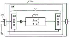
Fig. 2a shows a control device 201 according to an exemplary and non-limiting embodiment of the invention. The control device 201 comprises a processing system 204 constituting a signal processing path 211. In this exemplary case, the signal processing path 211 includes a finite impulse response "FIR" filter 212, which is a moving average filter having a z-domain transfer function of 1+ z-1+z-2+z-3+...+z-(N-1). The zero frequency gain (i.e., DC gain) of the FIR filter 212 is N because z is 1 at DC. The signal processing path 211 includes a gain g for setting the overall gain of the signal processing path 211 at a suitable level. The gain g may be, for example, 1/N to compensate for the DC gain of the FIR filter 212. The signal processing path 211 further comprises a decimator 213 preceding the FIR filter 212 and an interpolator 214 following the FIR filter. Decimator 213 causes FIR filteringThe sample rate of the input signal is less than the sample rate of the input signal and the interpolator 214 causes the sample rate of the output signal to be greater than the sample rate of the FIR filter 212. Advantageously, the interpolator 214 comprises a filter for suppressing an image of the output spectrum of the FIR filter 212 from the output signal of the control means 201. The decimator 213 may be provided with an anti-aliasing filter for preventing aliasing effects in the output signal of the decimator 213.
The amplitude response (i.e., the absolute value of the frequency response) of the signal processing path 211 is shown in fig. 2 b. The position of the transmission zero on the frequency axis (i.e. the zero of the amplitude response) depends on the sampling rate f of the input signal of the control device 201sLength N of FIR filter 212, and decimation rate NDSo that the frequency of the transmission zero is n × fs/(N×ND) The interpolation ratio has no similar effect on the frequency of the transfer zero, since in principle the interpolation adds an interpolated value between successive values of the time-discrete output signal of the FIR filter 212, but the sampling rate of the FIR filter 212 is not changed in this exemplary case the sampling rate of the input signal of the control means 201 is 1kHz, the length N of the FIR filter 212 is 100, and the decimation rate is 40 in this exemplary case the time length of the FIR filter 212 is 100 × 40 × 1ms 4 seconds, and thus the FIR filter 212 has a transfer zero at a frequency N × 0.25Hz, where N is a non-zero integer, when the length of the suspension rope 110 is about 4 meters, the first transfer zero frequency 0.25Hz is essentially the natural oscillation frequency f of the load 109N. Natural frequency of oscillation fNThis can be estimated by the following equation:

wherein g is the acceleration of gravity ≈ 9.82m/s2And l is the length of the suspension cord 110. The frequency of the first transmission zero of the FIR filter 212 is advantageously chosen to be the same as or slightly less than the minimum natural swinging frequency, i.e. the natural swinging frequency corresponding to the maximum length of the suspension ropes 110.
In accordance with the inventionIn the control apparatus of the exemplary and non-limiting embodiment, the input interface 202 of the control apparatus is configured to receive an indication of the natural oscillation frequency fNThe data of (1). The processing system 204 is configured to vary the decimation rate N of the decimator 213 according to the variation of the natural wobble frequencyD. The data may represent, for example, the natural wobble frequency fNOr the length l of the suspension rope 110, on the basis of which length l of the suspension rope 110 the natural swinging frequency f can be calculated according to the above equation 1N. The decimation rate N can be selectedDSo that the frequency f of the first transmission zeros/(N×ND) With natural oscillation frequency fNIs the same as or slightly less than the natural oscillating frequency fN. Interpolation ratio advantageously related to decimation rate NDTogether to have a constant sampling rate at the output of the control means.
Fig. 3 shows a control device 301 according to an exemplary and non-limiting embodiment of the invention. The control device 301 comprises a processing system 304 constituting a signal processing path 311. In this exemplary case, signal processing path 311 comprises a FIR filter 312, which FIR filter 312 is a moving average filter having a z-domain transfer function of 1+ z-1+z-2+z-3+...+z-(N1+N2-1). In this exemplary case, the signal processing path 311 includes an input shaper 315 for limiting the rate of change of the filter input signal provided to the FIR filter 312. The input shaper 315 is configured to limit the absolute value of the difference between the filter input signal and the delayed version (delayed version) of the filter input signal. In the exemplary case shown in fig. 3, the time period between the filter input signal and the delayed version of the filter input signal is N1 cycles of operation of the FIR filter 312, and the absolute value of the difference is limited to a maximum Δ max. The input shaper 315 is non-linear and therefore the input shaper 315 may generate new frequency components, which may in some cases occur at or near the natural swing frequency of the load. However, the FIR filter 312 suppresses the signal component whose frequency is the natural swing frequency and thus eliminates the leading by the input shaper 315And possible undesired excitation effects. Thus, any suitable non-linear input shaper may be inserted upstream of the FIR filter 312. Optionally, an input shaper may also be inserted into the FIR filter 312. In the exemplary and non-limiting case where signal processing path 311 includes multiple FIR filters, the input shaper may be inserted in the FIR filter that is first in the direction of the signal stream. The input shaper 315 performs acceleration and deceleration ramps, which may be necessary, for example, during speed reversals.
As can be seen from fig. 2b, the worst point attenuation on the first sideband of the moving average FIR filter (i.e. between the first and second transfer zeros) is very small. Therefore, in many cases, it is necessary to change the frequency of the transmission zero in accordance with the natural oscillation frequency of the load. As described above, the frequency of the transfer zero can be changed, for example, by adjusting a decimation function performed before the FIR filter. Another approach is to use an additional filter for placing additional attenuation over one or more frequency bands between successive transfer zeros of the FIR filter. Fig. 4a shows a control device 401 according to an exemplary and non-limiting embodiment of the invention. The control device 401 comprises a processing system 404 constituting a signal processing path 411. In this exemplary case, the signal processing path 411 comprises a FIR filter 412, said FIR filter 412 comprising two FIR filters 412a and 412b connected in series. There may also be three or more FIR filters connected in series. The impulse response of FIR filter 412 is the convolution of the impulse responses of FIR filters 412a and 412 b. In the exemplary case shown in FIG. 4a, FIR filter 412a is a z-domain transfer function of 1+ z-1+z-2+...+z-(N1+N2-1)And FIR filter 412b is a z-domain transfer function of 1+ z-1+z-2+...+z-(N3-1)The moving average filter of (1). In the exemplary case, the length N1+ N2 of FIR filter 412a is 100, while the length N3 of FIR filter 412b is 71, and thus the series-connected z-domain transfer function of FIR filters 412a and 412b is:

where g is the gain used to set the overall gain of the signal processing path 411 at an appropriate level. The gain g may be, for example, 1/7100 to compensate for the DC gains 100 and 71 of the FIR filters 412a and 412 b.
In the above exemplary case, the first transfer zero of FIR filter 412b is located approximately in the middle of the frequency band between the first transfer zero and the second transfer zero of FIR filter 412 a. The magnitude responses of FIR filters 412a and 412b and the magnitude responses of the series connection of FIR filters 412a and 412b are shown in fig. 4 b. The magnitude response of FIR filter 412a is represented by reference numeral 416, the magnitude response of FIR filter 412b is represented by reference numeral 417, and the magnitude response of the series connection of FIR filters 412a and 412b is represented by reference numeral 418. In the exemplary case of three series-connected moving average FIR filters, the length of the two shortest ones of the filters may be, for example, 0.82 and 0.62 times the length of the longest ones of the filters. This choice provides good attenuation over the frequency region above the first transmission zero of the longest of the filters.
The impulse response of the series connection of moving average FIR filters is symmetric in the time domain and can be very long. Therefore, the response latency of the control device may be too long in some cases. Therefore, in some cases it is advantageous to replace the moving average FIR filter with an FIR filter or an infinite impulse response "IIR" filter where the impulse response is asymmetric in the time domain, so that the impulse response has most of the energy of the impulse response in the beginning of the impulse response. The filter with an asymmetric impulse response may for example be a minimum phase filter.
Fig. 5a shows a control device 501 according to an exemplary and non-limiting embodiment of the invention. The control device 501 comprises a processing system 504 constituting a signal processing path 511. In this exemplary case, signal processing path 511 includes FIR filter 512, where FIR filter 512 is a z-domain transfer function of 1+ z-1+z-2+z-3+...+z-(N1+N2-1)The moving average filter of (1). Further, the signal processing path 511 includes a band-stop filter 519, the band-stop filter 519 having a stop band on a first side band of the finite impulse response filter 512. The band-stop filter 519 is located downstream of the interpolator 214, and therefore the sample rate of the band-stop filter 519 is the output sample rate of the interpolator 214. In FIG. 5a, z-1Represents the delay of one sample interval corresponding to the sampling rate of the FIR filter 512, and Z-1Representing a delay corresponding to one sample interval of the sample rate of the band stop filter 519. The band-stop filter 519 may be, for example, an IIR filter whose transfer function in the Z-domain is:

wherein P (Z)-1) And Q (Z)-1) Is Z-1A polynomial of (c). However, the band-stop filter may also be located upstream of the interpolator 214, in which case the sampling rate of the band-stop filter is the same as the sampling rate of the FIR filter.
The band-stop filter 519 may be, for example, a time-discrete equivalent of a time-continuous filter with a laplace domain transfer function as follows:

where s is the Laplace variable, ωzIs the frequency of the transmission zero, i.e. the notch frequency, and k is the damping factor by means of which the shape of the frequency response can be adjusted. The damping factor k may be adjusted, for example, experimentally. In some exemplary cases, 1.7 has proven to be a suitable value for the damping factor k. The time-continuous transfer function represented by equation 3 can be converted into its time dispersion equivalent by means of suitable conversion rules. For example, the following trapezoidal rule maps the left half s-plane to the inside of the origin centered unit circle of the Z-plane:

where T is the length of time of the sampling interval corresponding to the sampling rate of the band stop filter 519. Fig. 5b shows the magnitude response, i.e. the absolute value of the frequency response, of the combination of the FIR filter 512 and the band stop filter 519 in the case where the length N1+ N2 of the FIR filter 512 is 100 and the band stop filter 519 is the time discrete equivalent of a time continuous filter, the transfer function of the band stop filter 519 being based on equation 3, where the notch frequency ω is based on the absolute value of the frequency responsezBetween the first and second pass zeros of FIR filter 512, and the damping factor k is 1.7.
The notch frequency ω of the band reject filter 519 may also be adjustedzThe natural oscillation frequency corresponding to the maximum rope length is selected and the FIR filter 512 is designed as a moving average filter with its first transfer zero at the natural oscillation frequency corresponding to half the maximum rope length. This makes the operation faster, but may provide less damping at the natural oscillation frequency corresponding to the short rope length.
The band stop filter 519 may also be designed directly in the Z domain. For example, the Z-domain transfer function of a second order IIR band-stop filter may be:

wherein z isz=ejωzT、zz *=e-jωzT、zz=rpejωpT、zz *=rpe-jωpT,ωzIs the notch frequency, T is the length of time of the sampling interval corresponding to the sampling rate of the band stop filter 519, rpIs the polar radius, ωpIs the pole frequency, j is the imaginary unit, and g is a coefficient that can be selected, for example, such that the gain at the zero frequency (i.e., the DC gain) has a desired value. Due to zzAnd zz *Are complex conjugates of each other, and accordingly zpAnd zp *Are complex conjugates of each other, the transfer function represented by equation 5 can be presented in a form having real-valued coefficients. Can pass throughAdjusting the polar radius rpAnd pole frequency ωpTo adjust the shape of the frequency response.
The processing system of the control device according to exemplary and non-limiting embodiments of the invention (e.g., processing systems 104, 204, 304, 404, and 504 shown in the figures) may be implemented by one or more processor circuits, each of which may be a programmable processor circuit provided with appropriate software, a special-purpose hardware processor (e.g., an application-specific integrated circuit "ASIC"), or a configurable hardware processor (such as, for example, a field programmable gate array "FPGA"). Further, the processing system may include one or more memory devices, each of which may be, for example, a random access memory "RAM" circuit.
The above-described control devices 101, 201, 301, 401, and 501 are examples of control devices including:
means for receiving an input signal indicative of a target speed of a load, the load being non-rigidly connected to a suspension point whose speed and position are controllable;
means for forming a signal processing path, the means comprising a finite impulse response filter for suppressing signal components whose frequency is the natural swing frequency of the load;
means for providing an input signal to a signal processing path to generate an output signal indicative of a reference velocity of the suspension point; and
means for controlling the movement of the suspension point in dependence on the output signal of the signal processing path.
Fig. 6 shows a flow chart of a method for controlling the movement of a load that is not rigidly connected to a suspension point whose speed and position are controllable, according to an exemplary and non-limiting embodiment of the invention. The method comprises the acts of:
act 601: receiving an input signal indicative of a target speed of a load;
act 602: providing the input signal to a signal processing path to generate an output signal indicative of a reference velocity of the suspension point, the signal processing path comprising at least one finite impulse response filter for suppressing signal components whose frequency is the natural swing frequency of the load; and
act 603: the movement of the suspension point is controlled in dependence on the output signal of the signal processing path.
In a method according to an exemplary and non-limiting embodiment of the invention, at least one finite impulse response filter has a transfer zero at or near a natural swing frequency of the load. In a method according to an exemplary and non-limiting embodiment of the invention, the at least one finite impulse response filter comprises a moving average filter.
In a method according to an exemplary and non-limiting embodiment of the invention, the at least one finite impulse response filter comprises at least two finite impulse response filters connected in series or in parallel. The impulse response of the series connection of finite impulse response filters is a convolution of the impulse responses of the series connection of finite impulse response filters. In a method according to an exemplary and non-limiting embodiment of the invention, the at least two finite impulse response filters comprise moving average filters.
In a method according to an exemplary and non-limiting embodiment of the invention, the signal processing path includes a band-stop filter having a stop band on a first side band of at least one finite impulse response filter. In a method according to an exemplary and non-limiting embodiment of the invention, the band-stop filter is an infinite impulse response filter. In a method according to an exemplary and non-limiting embodiment of the invention, the band-stop filter is a minimum phase filter.
In a method according to an exemplary and non-limiting embodiment of the invention, the signal processing path includes a decimator located before the at least one finite impulse response filter and an interpolator located after the at least one finite impulse response filter. The decimator causes the sampling rate of the at least one finite impulse response filter to be less than the sampling rate of the input signal and the interpolator causes the sampling rate of the output signal to be greater than the sampling rate of the at least one finite impulse response filter.
A method according to an exemplary and non-limiting embodiment of the present invention includes receiving data indicative of a natural wobble frequency and varying a decimation rate of the decimator in accordance with a change in the natural wobble frequency.
In a method according to an exemplary and non-limiting embodiment of the invention, the signal processing path includes an input shaper that limits a rate of change of a filter input signal provided to the at least one finite impulse response filter. The input shaper is advantageously inserted upstream of the at least one finite impulse response filter or the input shaper is integrated into a first one of the at least one finite impulse response filter. In a method according to an exemplary and non-limiting embodiment of the invention, the input shaper limits the absolute value of the difference between the filter input signal and the delayed version of the filter input signal.
The computer program according to any of the above exemplary and non-limiting embodiments of the invention comprises computer executable instructions for controlling a programmable processor to perform actions relating to a method according to any of the above exemplary and non-limiting embodiments of the invention.
The computer program according to an exemplary and non-limiting embodiment of the invention comprises a software module for controlling the movement of a load that is non-rigidly connected to a suspension point whose speed and position are controllable. The software modules include computer-executable instructions for controlling a programmable processor to:
forming a signal processing path including at least one finite impulse response filter for suppressing signal components whose frequencies are the natural swing frequency of the load;
receiving an input signal indicative of a target speed of a load;
providing the input signal to a signal processing path to generate an output signal indicative of a reference velocity of the suspension point; and
the movement of the suspension point is controlled in dependence on the output signal of the signal processing path.
The software modules described above may be, for example, subroutines and/or functions implemented in a programming language suitable for the programmable processor in question.
The computer program product according to an exemplary and non-limiting embodiment of the present invention includes a computer readable medium, such as a computer optical disc "CD", which uses encoded computer programs according to exemplary embodiments of the present invention.
Signals according to exemplary and non-limiting embodiments of the present invention are encoded to carry information of a computer program defined according to exemplary embodiments of the present invention.
The non-limiting specific examples provided in the description given above should not be construed as limiting the scope and/or applicability of the appended claims. Moreover, any list or set of examples provided herein is not exhaustive unless explicitly stated otherwise.
While the invention has been illustrated and described with respect to specific embodiments thereof, it will be appreciated by those skilled in the art that various modifications may be made without departing from the spirit and scope of the disclosure.
Claims (19)
1. A control device for controlling the movement of a load non-rigidly connected to a suspension point, the control device comprising:
an input interface for receiving an input signal indicative of a target speed of the load;
an output interface for providing an output signal indicative of a reference velocity of the suspension point; and
a processing system constituting a signal processing path for generating the output signal from the input signal,
wherein the signal processing path comprises at least one finite impulse response filter for suppressing signal components whose frequency is the natural swing frequency of the load,
wherein the signal processing path comprises a decimator located before the at least one finite impulse response filter and an interpolator located after the at least one finite impulse response filter, the decimator causing the sampling rate of the at least one finite impulse response filter to be less than the sampling rate of the input signal and the interpolator causing the sampling rate of the output signal to be greater than the sampling rate of the at least one finite impulse response filter.
2. The control device of claim 1, wherein the at least one finite impulse response filter comprises more than one finite impulse response filter connected in series or parallel with each other.
3. The control apparatus of claim 1, wherein the at least one finite impulse response filter has a transfer zero at or near a natural swing frequency of the load.
4. The control device of claim 1, wherein the at least one finite impulse response filter comprises a moving average filter.
5. The control apparatus of claim 1, wherein the signal processing path further comprises at least one band-stop filter having a stopband on a first sideband of the at least one finite impulse response filter, the at least one band-stop filter connected in series with the at least one finite impulse response filter, the at least one band-stop filter disposed downstream of the at least one finite impulse response filter, and the at least one band-stop filter comprising an infinite impulse response filter.
6. The control device of claim 1, wherein the input interface is configured to receive data indicative of the natural oscillation frequency, and the processing system is configured to vary a decimation rate of the decimator as a function of the natural oscillation frequency.
7. The control apparatus of claim 1, wherein the signal processing path includes an input shaper for limiting a rate of change of a filter input signal provided to the at least one finite impulse response filter, the input shaper being inserted in a first one of the finite impulse response filters that is first in a signal flow direction upstream of or integrated into the at least one finite impulse response filter.
8. The control apparatus of claim 7, wherein the input shaper is configured to limit an absolute value of a difference between the delayed version of the filter input signal and the filter input signal.
9. A system for manipulating a load, the system comprising:
a carrier comprising a suspension point for carrying a load and a controllable drive for moving the suspension point, wherein the load is non-rigidly connected to the suspension point; and
control means for receiving an input signal indicative of a target speed of the load and for providing an output signal indicative of a reference speed of the suspension point to the controllable driver,
wherein the control device comprises:
an input interface for receiving the input signal;
an output interface for providing the output signal to the controllable driver; and
a processing system constituting a signal processing path for generating the output signal based on the input signal, the signal processing path comprising at least one finite impulse response filter for suppressing signal components whose frequency is a natural swing frequency of a load,
wherein the signal processing path comprises a decimator located before the at least one finite impulse response filter and an interpolator located after the at least one finite impulse response filter, the decimator causing the sampling rate of the at least one finite impulse response filter to be less than the sampling rate of the input signal and the interpolator causing the sampling rate of the output signal to be greater than the sampling rate of the at least one finite impulse response filter.
10. A system according to claim 9, wherein the load carrying means is a crane for carrying the load, the crane having a suspension line connected to the suspension point.
11. A method for controlling the movement of a load non-rigidly connected to a suspension point, the method comprising:
receiving an input signal indicative of a target speed of the load;
providing the input signal to a signal processing path to generate an output signal indicative of a reference velocity of the suspension point, an
Controlling the movement of the suspension point in dependence on the output signal of the signal processing path,
wherein the signal processing path comprises at least one finite impulse response filter for suppressing signal components having a frequency of a natural swing frequency of the load,
the signal processing path includes a decimator located before the at least one finite impulse response filter and an interpolator located after the at least one finite impulse response filter, the decimator causing the sampling rate of the at least one finite impulse response filter to be less than the sampling rate of the input signal and the interpolator causing the sampling rate of the output signal to be greater than the sampling rate of the at least one finite impulse response filter.
12. The method of claim 11, wherein the at least one finite impulse response filter comprises more than one finite impulse response filter connected in series or parallel with each other.
13. The method of claim 11, wherein the at least one finite impulse response filter has a transfer zero at or near a natural swing frequency of the load.
14. The method of claim 11, wherein the at least one finite impulse response filter comprises a moving average filter.
15. The method of claim 11, wherein the signal processing path further comprises at least one band-stop filter having a stopband on a first sideband of the at least one finite impulse response filter, the at least one band-stop filter connected in series with the at least one finite impulse response filter, the at least one band-stop filter disposed downstream of the at least one finite impulse response filter, and the at least one band-stop filter comprising an infinite impulse response filter.
16. The method of claim 11, wherein the method comprises:
receiving data indicating the natural wobble frequency and varying a decimation rate of the decimator in accordance with a change in the natural wobble frequency.
17. The method of claim 11, wherein the signal processing path includes an input shaper that limits a rate of change of a filter input signal provided to the at least one finite impulse response filter, the input shaper being inserted upstream of the at least one finite impulse response filter or being integrated into a first one of the at least one finite impulse response filter that is first in a signal flow direction.
18. The method of claim 17, wherein the input shaper limits an absolute value of a difference between the delayed version of the filter input signal and the filter input signal.
19. A non-transitory computer-readable medium encoded with a computer program for controlling movement of a load non-rigidly connected to a suspension point, the computer program comprising computer-executable instructions for controlling a programmable processor to:
forming a signal processing path;
receiving an input signal indicative of the load target speed;
providing the input signal to the signal processing path to generate an output signal indicative of a reference velocity of the suspension point; and
controlling the movement of the suspension point in dependence on the output signal of the signal processing path,
wherein the computer program comprises computer-executable instructions for configuring the signal processing path to comprise at least one finite impulse response filter for suppressing signal components whose frequency is the natural swing frequency of the load,
wherein the signal processing path comprises a decimator located before the at least one finite impulse response filter and an interpolator located after the at least one finite impulse response filter, the decimator causing the sampling rate of the at least one finite impulse response filter to be less than the sampling rate of the input signal and the interpolator causing the sampling rate of the output signal to be greater than the sampling rate of the at least one finite impulse response filter.
Applications Claiming Priority (2)
| Application Number | Priority Date | Filing Date | Title |
|---|---|---|---|
| US15/955,141 US10696523B2 (en) | 2018-04-17 | 2018-04-17 | Control device and method for controlling motion of a load |
| US15/955,141 | 2018-04-17 |
Publications (2)
| Publication Number | Publication Date |
|---|---|
| CN110386552A CN110386552A (en) | 2019-10-29 |
| CN110386552B true CN110386552B (en) | 2020-08-28 |
Family
ID=68053208
Family Applications (1)
| Application Number | Title | Priority Date | Filing Date |
|---|---|---|---|
| CN201910302694.7A Active CN110386552B (en) | 2018-04-17 | 2019-04-15 | Control device and method for controlling the movement of a load |
Country Status (3)
| Country | Link |
|---|---|
| US (1) | US10696523B2 (en) |
| CN (1) | CN110386552B (en) |
| DE (1) | DE102019107677A1 (en) |
Families Citing this family (4)
| Publication number | Priority date | Publication date | Assignee | Title |
|---|---|---|---|---|
| DE102020126504A1 (en) | 2020-10-09 | 2022-04-14 | Liebherr-Werk Biberach Gmbh | Hoist such as a crane and method and device for controlling such a hoist |
| CN113336097B (en) * | 2021-06-30 | 2023-08-22 | 三一汽车起重机械有限公司 | Crane rotation control method, crane rotation control device, electronic equipment and storage medium |
| WO2024120198A1 (en) * | 2022-12-06 | 2024-06-13 | Huawei Technologies Co., Ltd. | Method for load tracking and related device |
| CN117208759B (en) * | 2023-09-28 | 2026-03-24 | 沈阳理工大学 | Tower crane, filter design methods, computer devices, readable storage media |
Citations (6)
| Publication number | Priority date | Publication date | Assignee | Title |
|---|---|---|---|---|
| FI91517B (en) * | 1992-11-17 | 1994-03-31 | Kimmo Hytoenen | Method for controlling a harmonically oscillating load |
| US5960969A (en) * | 1996-01-26 | 1999-10-05 | Habisohn; Chris Xavier | Method for damping load oscillations on a crane |
| CN103998367A (en) * | 2011-09-20 | 2014-08-20 | 科恩起重机有限公司 | Crane control |
| US9385737B1 (en) * | 2014-12-11 | 2016-07-05 | Maxin Integrated Products, Inc. | Adaptive correction of interleaving errors in time-interleaved analog-to-digital converters |
| CN106927366A (en) * | 2017-02-10 | 2017-07-07 | 武汉港迪智能技术有限公司 | A kind of overhead and gantry cranes open loop is anti-to shake method |
| CN106959610A (en) * | 2017-04-05 | 2017-07-18 | 山东大学 | Bridge crane system APD‑SMC controller, bridge crane system and control method |
Family Cites Families (10)
| Publication number | Priority date | Publication date | Assignee | Title |
|---|---|---|---|---|
| WO1993008115A1 (en) * | 1991-10-18 | 1993-04-29 | Kabushiki Kaisha Yaskawa Denki | Method and apparatus for controlling prevention of deflection of rope of crane |
| US5359542A (en) * | 1991-12-20 | 1994-10-25 | The Boeing Company | Variable parameter collision avoidance system for aircraft work platforms |
| DE10201202B4 (en) * | 2002-01-14 | 2009-11-26 | Otmar Fahrion | Docking unit for servicing an aircraft or the like |
| WO2008076500A2 (en) * | 2006-10-24 | 2008-06-26 | 3M Innovative Properties Company | Stock roll direct load system |
| US7367464B1 (en) * | 2007-01-30 | 2008-05-06 | The United States Of America As Represented By The Secretary Of The Navy | Pendulation control system with active rider block tagline system for shipboard cranes |
| WO2008099611A1 (en) * | 2007-02-14 | 2008-08-21 | Gogou Co., Ltd. | Movement control method, movement operating device, and method for operating movement of moving body |
| US7725287B2 (en) * | 2007-07-27 | 2010-05-25 | Tm Ge Automation Systems, Llc | System and method for using structured shapes to increase laser scanner accuracy |
| US20090164345A1 (en) * | 2007-12-21 | 2009-06-25 | Tideworks Technology, Inc. | System and method for management and control of containerized freight |
| SI2398621T1 (en) * | 2009-01-20 | 2019-08-30 | Lasercoil Technologies, Llc | Laser blanking from coil strip profile conveyor system |
| US8352128B2 (en) * | 2009-09-25 | 2013-01-08 | TMEIC Corp. | Dynamic protective envelope for crane suspended loads |
-
2018
- 2018-04-17 US US15/955,141 patent/US10696523B2/en active Active
-
2019
- 2019-03-26 DE DE102019107677.3A patent/DE102019107677A1/en active Pending
- 2019-04-15 CN CN201910302694.7A patent/CN110386552B/en active Active
Patent Citations (6)
| Publication number | Priority date | Publication date | Assignee | Title |
|---|---|---|---|---|
| FI91517B (en) * | 1992-11-17 | 1994-03-31 | Kimmo Hytoenen | Method for controlling a harmonically oscillating load |
| US5960969A (en) * | 1996-01-26 | 1999-10-05 | Habisohn; Chris Xavier | Method for damping load oscillations on a crane |
| CN103998367A (en) * | 2011-09-20 | 2014-08-20 | 科恩起重机有限公司 | Crane control |
| US9385737B1 (en) * | 2014-12-11 | 2016-07-05 | Maxin Integrated Products, Inc. | Adaptive correction of interleaving errors in time-interleaved analog-to-digital converters |
| CN106927366A (en) * | 2017-02-10 | 2017-07-07 | 武汉港迪智能技术有限公司 | A kind of overhead and gantry cranes open loop is anti-to shake method |
| CN106959610A (en) * | 2017-04-05 | 2017-07-18 | 山东大学 | Bridge crane system APD‑SMC controller, bridge crane system and control method |
Also Published As
| Publication number | Publication date |
|---|---|
| US10696523B2 (en) | 2020-06-30 |
| US20190315601A1 (en) | 2019-10-17 |
| CN110386552A (en) | 2019-10-29 |
| DE102019107677A1 (en) | 2019-10-17 |
Similar Documents
| Publication | Publication Date | Title |
|---|---|---|
| CN110386552B (en) | Control device and method for controlling the movement of a load | |
| JP6192559B2 (en) | Crane equipment | |
| JP5899547B2 (en) | Electric motor control device | |
| KR101606963B1 (en) | Apparatus and method for controlling actuator in optical image stabilizer and optical image stabilizer using the same | |
| JP5825953B2 (en) | Integrated upsampler and filtering for multi-speed controller of electromechanical flight actuation system | |
| CN111347418B (en) | Method for controlling electric control servo system, electric control servo system and robot | |
| JP4311043B2 (en) | Electric motor control device | |
| CN101103517B (en) | Motor control device | |
| JP6118988B2 (en) | Motor drive device | |
| US9354441B2 (en) | Method for adapting the parameters of a controller for micromechanical actuators, and device | |
| JP5469949B2 (en) | Electric machine control device | |
| US9310606B2 (en) | Controller for actuating a micromechanical actuator, actuating system for actuating a micromechanical actuator, micro-mirror system and method for actuating a micromechanical actuator | |
| JP6018403B2 (en) | Driving circuit for voice coil motor with spring return mechanism, lens module and electronic device using the same | |
| KR20160093257A (en) | Optical image stabilizer and camera module including the same | |
| EP0774176B1 (en) | Filter, repetitive control system and learning control system both provided with such filter | |
| KR102149391B1 (en) | Optical image stabilizer and camera module including the same | |
| Zhang et al. | A Method of Enhancing Fast Steering Mirror’s Ability of Anti‐Disturbance Based on Adaptive Robust Control | |
| JP5425044B2 (en) | Adaptive notch filter and parameter adjustment method for notch filter | |
| JP6524673B2 (en) | Circuit device, physical quantity detection device, electronic device and moving body | |
| CN108775373B (en) | Vibration suppression method for servo motor and load multistage transmission system | |
| JP2015114221A (en) | Signal processing device, detection device, sensor, electronic device, and movable body | |
| CN108233922B (en) | Feedback signal frequency division phase shifting system of vibrating table | |
| CN106292555B (en) | For packing, filling or dispensing control system and method | |
| JP2010220278A (en) | Motor controller | |
| CN108254147B (en) | Vibrating table feedback signal frequency band amplitude modulation system |
Legal Events
| Date | Code | Title | Description |
|---|---|---|---|
| PB01 | Publication | ||
| PB01 | Publication | ||
| SE01 | Entry into force of request for substantive examination | ||
| SE01 | Entry into force of request for substantive examination | ||
| GR01 | Patent grant | ||
| GR01 | Patent grant |