CN110383021B - Blood pressure measurement system using resistive force sensor array - Google Patents
Blood pressure measurement system using resistive force sensor array Download PDFInfo
- Publication number
- CN110383021B CN110383021B CN201780087901.0A CN201780087901A CN110383021B CN 110383021 B CN110383021 B CN 110383021B CN 201780087901 A CN201780087901 A CN 201780087901A CN 110383021 B CN110383021 B CN 110383021B
- Authority
- CN
- China
- Prior art keywords
- sensor
- conductive
- sensing
- pressure
- mechanical element
- Prior art date
- Legal status (The legal status is an assumption and is not a legal conclusion. Google has not performed a legal analysis and makes no representation as to the accuracy of the status listed.)
- Active
Links
- 238000009530 blood pressure measurement Methods 0.000 title description 18
- 239000000758 substrate Substances 0.000 claims abstract description 24
- 230000008859 change Effects 0.000 claims abstract description 16
- 230000036772 blood pressure Effects 0.000 claims description 44
- 239000000463 material Substances 0.000 claims description 44
- 239000012528 membrane Substances 0.000 claims description 32
- 239000007779 soft material Substances 0.000 claims description 28
- 230000006870 function Effects 0.000 claims description 22
- 239000004205 dimethyl polysiloxane Substances 0.000 claims description 16
- 229920000435 poly(dimethylsiloxane) Polymers 0.000 claims description 16
- 229920001296 polysiloxane Polymers 0.000 claims description 12
- 210000000707 wrist Anatomy 0.000 claims description 10
- 239000004033 plastic Substances 0.000 claims description 9
- 229920003023 plastic Polymers 0.000 claims description 9
- 229920000642 polymer Polymers 0.000 claims description 9
- 230000007423 decrease Effects 0.000 claims description 8
- -1 Polydimethylsiloxane Polymers 0.000 claims description 6
- 239000004568 cement Substances 0.000 claims description 6
- 239000011347 resin Substances 0.000 claims description 6
- 229920005989 resin Polymers 0.000 claims description 6
- 238000012546 transfer Methods 0.000 claims description 5
- 239000004020 conductor Substances 0.000 abstract description 22
- 230000009975 flexible effect Effects 0.000 abstract description 9
- 239000000560 biocompatible material Substances 0.000 abstract description 3
- 238000010586 diagram Methods 0.000 description 35
- 238000004891 communication Methods 0.000 description 22
- 230000033001 locomotion Effects 0.000 description 18
- 210000004204 blood vessel Anatomy 0.000 description 17
- 238000012545 processing Methods 0.000 description 15
- 238000000034 method Methods 0.000 description 12
- 206010020772 Hypertension Diseases 0.000 description 10
- 210000000056 organ Anatomy 0.000 description 10
- 230000008901 benefit Effects 0.000 description 9
- 239000011888 foil Substances 0.000 description 9
- 230000036541 health Effects 0.000 description 9
- 238000005259 measurement Methods 0.000 description 9
- 238000012544 monitoring process Methods 0.000 description 9
- 239000008280 blood Substances 0.000 description 8
- 210000004369 blood Anatomy 0.000 description 8
- 230000007246 mechanism Effects 0.000 description 8
- 210000002321 radial artery Anatomy 0.000 description 8
- 210000001367 artery Anatomy 0.000 description 7
- 210000002559 ulnar artery Anatomy 0.000 description 7
- 238000003491 array Methods 0.000 description 6
- 238000013186 photoplethysmography Methods 0.000 description 6
- 230000004048 modification Effects 0.000 description 5
- 238000012986 modification Methods 0.000 description 5
- 230000003287 optical effect Effects 0.000 description 5
- 230000000007 visual effect Effects 0.000 description 5
- 238000005516 engineering process Methods 0.000 description 4
- 230000008569 process Effects 0.000 description 4
- 230000004044 response Effects 0.000 description 4
- 230000005236 sound signal Effects 0.000 description 4
- 230000035488 systolic blood pressure Effects 0.000 description 4
- 230000017531 blood circulation Effects 0.000 description 3
- 210000002302 brachial artery Anatomy 0.000 description 3
- 230000001419 dependent effect Effects 0.000 description 3
- 230000003205 diastolic effect Effects 0.000 description 3
- 229920001971 elastomer Polymers 0.000 description 3
- 210000003414 extremity Anatomy 0.000 description 3
- 230000007774 longterm Effects 0.000 description 3
- 229910052751 metal Inorganic materials 0.000 description 3
- 239000002184 metal Substances 0.000 description 3
- 238000003032 molecular docking Methods 0.000 description 3
- 230000003068 static effect Effects 0.000 description 3
- XLYOFNOQVPJJNP-UHFFFAOYSA-N water Substances O XLYOFNOQVPJJNP-UHFFFAOYSA-N 0.000 description 3
- 206010019280 Heart failures Diseases 0.000 description 2
- HBBGRARXTFLTSG-UHFFFAOYSA-N Lithium ion Chemical compound [Li+] HBBGRARXTFLTSG-UHFFFAOYSA-N 0.000 description 2
- 238000013459 approach Methods 0.000 description 2
- 230000036760 body temperature Effects 0.000 description 2
- 239000006229 carbon black Substances 0.000 description 2
- 239000000835 fiber Substances 0.000 description 2
- 230000005802 health problem Effects 0.000 description 2
- 230000001939 inductive effect Effects 0.000 description 2
- 230000010354 integration Effects 0.000 description 2
- 229910001416 lithium ion Inorganic materials 0.000 description 2
- 230000005499 meniscus Effects 0.000 description 2
- 208000010125 myocardial infarction Diseases 0.000 description 2
- 239000005060 rubber Substances 0.000 description 2
- 238000010079 rubber tapping Methods 0.000 description 2
- 230000035807 sensation Effects 0.000 description 2
- 208000024891 symptom Diseases 0.000 description 2
- 208000024172 Cardiovascular disease Diseases 0.000 description 1
- WQZGKKKJIJFFOK-GASJEMHNSA-N Glucose Natural products OC[C@H]1OC(O)[C@H](O)[C@@H](O)[C@@H]1O WQZGKKKJIJFFOK-GASJEMHNSA-N 0.000 description 1
- 241000282412 Homo Species 0.000 description 1
- 208000006011 Stroke Diseases 0.000 description 1
- 208000005434 White Coat Hypertension Diseases 0.000 description 1
- 230000001133 acceleration Effects 0.000 description 1
- 239000000853 adhesive Substances 0.000 description 1
- 230000001070 adhesive effect Effects 0.000 description 1
- 229910052782 aluminium Inorganic materials 0.000 description 1
- XAGFODPZIPBFFR-UHFFFAOYSA-N aluminium Chemical compound [Al] XAGFODPZIPBFFR-UHFFFAOYSA-N 0.000 description 1
- 208000011775 arteriosclerosis disease Diseases 0.000 description 1
- QVGXLLKOCUKJST-UHFFFAOYSA-N atomic oxygen Chemical compound [O] QVGXLLKOCUKJST-UHFFFAOYSA-N 0.000 description 1
- 230000004888 barrier function Effects 0.000 description 1
- 239000003990 capacitor Substances 0.000 description 1
- 230000001413 cellular effect Effects 0.000 description 1
- 239000000919 ceramic Substances 0.000 description 1
- 230000001684 chronic effect Effects 0.000 description 1
- 230000004087 circulation Effects 0.000 description 1
- 230000000295 complement effect Effects 0.000 description 1
- 239000002131 composite material Substances 0.000 description 1
- 238000004590 computer program Methods 0.000 description 1
- 238000012790 confirmation Methods 0.000 description 1
- 239000006059 cover glass Substances 0.000 description 1
- 239000013078 crystal Substances 0.000 description 1
- 238000003745 diagnosis Methods 0.000 description 1
- 230000035487 diastolic blood pressure Effects 0.000 description 1
- 201000010099 disease Diseases 0.000 description 1
- 208000037265 diseases, disorders, signs and symptoms Diseases 0.000 description 1
- 238000002651 drug therapy Methods 0.000 description 1
- 230000000694 effects Effects 0.000 description 1
- 239000000806 elastomer Substances 0.000 description 1
- 230000007613 environmental effect Effects 0.000 description 1
- 238000001914 filtration Methods 0.000 description 1
- 238000007667 floating Methods 0.000 description 1
- 239000011521 glass Substances 0.000 description 1
- 239000008103 glucose Substances 0.000 description 1
- 239000003292 glue Substances 0.000 description 1
- PCHJSUWPFVWCPO-UHFFFAOYSA-N gold Chemical compound [Au] PCHJSUWPFVWCPO-UHFFFAOYSA-N 0.000 description 1
- 229910052737 gold Inorganic materials 0.000 description 1
- 239000010931 gold Substances 0.000 description 1
- 235000004280 healthy diet Nutrition 0.000 description 1
- 208000019622 heart disease Diseases 0.000 description 1
- 230000001631 hypertensive effect Effects 0.000 description 1
- 230000001976 improved effect Effects 0.000 description 1
- 230000006872 improvement Effects 0.000 description 1
- 239000010985 leather Substances 0.000 description 1
- 239000007788 liquid Substances 0.000 description 1
- 238000012423 maintenance Methods 0.000 description 1
- 229910001092 metal group alloy Inorganic materials 0.000 description 1
- 229910044991 metal oxide Inorganic materials 0.000 description 1
- 150000004706 metal oxides Chemical class 0.000 description 1
- 230000000116 mitigating effect Effects 0.000 description 1
- 230000008520 organization Effects 0.000 description 1
- 229910052760 oxygen Inorganic materials 0.000 description 1
- 239000001301 oxygen Substances 0.000 description 1
- 239000005022 packaging material Substances 0.000 description 1
- 229920000098 polyolefin Polymers 0.000 description 1
- 239000010970 precious metal Substances 0.000 description 1
- 238000012913 prioritisation Methods 0.000 description 1
- 230000005855 radiation Effects 0.000 description 1
- 230000029058 respiratory gaseous exchange Effects 0.000 description 1
- 239000004065 semiconductor Substances 0.000 description 1
- 230000001953 sensory effect Effects 0.000 description 1
- 238000000926 separation method Methods 0.000 description 1
- 229910052709 silver Inorganic materials 0.000 description 1
- 239000004332 silver Substances 0.000 description 1
- 239000010935 stainless steel Substances 0.000 description 1
- 229910001220 stainless steel Inorganic materials 0.000 description 1
- 230000008093 supporting effect Effects 0.000 description 1
- 230000001360 synchronised effect Effects 0.000 description 1
- 230000002123 temporal effect Effects 0.000 description 1
- 239000002023 wood Substances 0.000 description 1
Images


Classifications
-
- A—HUMAN NECESSITIES
- A61—MEDICAL OR VETERINARY SCIENCE; HYGIENE
- A61B—DIAGNOSIS; SURGERY; IDENTIFICATION
- A61B5/00—Measuring for diagnostic purposes; Identification of persons
- A61B5/02—Detecting, measuring or recording pulse, heart rate, blood pressure or blood flow; Combined pulse/heart-rate/blood pressure determination; Evaluating a cardiovascular condition not otherwise provided for, e.g. using combinations of techniques provided for in this group with electrocardiography or electroauscultation; Heart catheters for measuring blood pressure
- A61B5/021—Measuring pressure in heart or blood vessels
- A61B5/02141—Details of apparatus construction, e.g. pump units or housings therefor, cuff pressurising systems, arrangements of fluid conduits or circuits
-
- A—HUMAN NECESSITIES
- A61—MEDICAL OR VETERINARY SCIENCE; HYGIENE
- A61B—DIAGNOSIS; SURGERY; IDENTIFICATION
- A61B5/00—Measuring for diagnostic purposes; Identification of persons
- A61B5/68—Arrangements of detecting, measuring or recording means, e.g. sensors, in relation to patient
- A61B5/6801—Arrangements of detecting, measuring or recording means, e.g. sensors, in relation to patient specially adapted to be attached to or worn on the body surface
- A61B5/6802—Sensor mounted on worn items
- A61B5/681—Wristwatch-type devices
-
- A—HUMAN NECESSITIES
- A61—MEDICAL OR VETERINARY SCIENCE; HYGIENE
- A61B—DIAGNOSIS; SURGERY; IDENTIFICATION
- A61B5/00—Measuring for diagnostic purposes; Identification of persons
- A61B5/68—Arrangements of detecting, measuring or recording means, e.g. sensors, in relation to patient
- A61B5/6801—Arrangements of detecting, measuring or recording means, e.g. sensors, in relation to patient specially adapted to be attached to or worn on the body surface
- A61B5/6813—Specially adapted to be attached to a specific body part
- A61B5/6824—Arm or wrist
-
- A—HUMAN NECESSITIES
- A61—MEDICAL OR VETERINARY SCIENCE; HYGIENE
- A61B—DIAGNOSIS; SURGERY; IDENTIFICATION
- A61B5/00—Measuring for diagnostic purposes; Identification of persons
- A61B5/68—Arrangements of detecting, measuring or recording means, e.g. sensors, in relation to patient
- A61B5/6801—Arrangements of detecting, measuring or recording means, e.g. sensors, in relation to patient specially adapted to be attached to or worn on the body surface
- A61B5/683—Means for maintaining contact with the body
- A61B5/6831—Straps, bands or harnesses
-
- A—HUMAN NECESSITIES
- A61—MEDICAL OR VETERINARY SCIENCE; HYGIENE
- A61B—DIAGNOSIS; SURGERY; IDENTIFICATION
- A61B5/00—Measuring for diagnostic purposes; Identification of persons
- A61B5/74—Details of notification to user or communication with user or patient ; user input means
- A61B5/742—Details of notification to user or communication with user or patient ; user input means using visual displays
-
- G—PHYSICS
- G01—MEASURING; TESTING
- G01L—MEASURING FORCE, STRESS, TORQUE, WORK, MECHANICAL POWER, MECHANICAL EFFICIENCY, OR FLUID PRESSURE
- G01L23/00—Devices or apparatus for measuring or indicating or recording rapid changes, such as oscillations, in the pressure of steam, gas, or liquid; Indicators for determining work or energy of steam, internal-combustion, or other fluid-pressure engines from the condition of the working fluid
- G01L23/08—Devices or apparatus for measuring or indicating or recording rapid changes, such as oscillations, in the pressure of steam, gas, or liquid; Indicators for determining work or energy of steam, internal-combustion, or other fluid-pressure engines from the condition of the working fluid operated electrically
- G01L23/18—Devices or apparatus for measuring or indicating or recording rapid changes, such as oscillations, in the pressure of steam, gas, or liquid; Indicators for determining work or energy of steam, internal-combustion, or other fluid-pressure engines from the condition of the working fluid operated electrically by resistance strain gauges
-
- G—PHYSICS
- G01—MEASURING; TESTING
- G01L—MEASURING FORCE, STRESS, TORQUE, WORK, MECHANICAL POWER, MECHANICAL EFFICIENCY, OR FLUID PRESSURE
- G01L9/00—Measuring steady of quasi-steady pressure of fluid or fluent solid material by electric or magnetic pressure-sensitive elements; Transmitting or indicating the displacement of mechanical pressure-sensitive elements, used to measure the steady or quasi-steady pressure of a fluid or fluent solid material, by electric or magnetic means
- G01L9/02—Measuring steady of quasi-steady pressure of fluid or fluent solid material by electric or magnetic pressure-sensitive elements; Transmitting or indicating the displacement of mechanical pressure-sensitive elements, used to measure the steady or quasi-steady pressure of a fluid or fluent solid material, by electric or magnetic means by making use of variations in ohmic resistance, e.g. of potentiometers, electric circuits therefor, e.g. bridges, amplifiers or signal conditioning
- G01L9/06—Measuring steady of quasi-steady pressure of fluid or fluent solid material by electric or magnetic pressure-sensitive elements; Transmitting or indicating the displacement of mechanical pressure-sensitive elements, used to measure the steady or quasi-steady pressure of a fluid or fluent solid material, by electric or magnetic means by making use of variations in ohmic resistance, e.g. of potentiometers, electric circuits therefor, e.g. bridges, amplifiers or signal conditioning of piezo-resistive devices
-
- A—HUMAN NECESSITIES
- A61—MEDICAL OR VETERINARY SCIENCE; HYGIENE
- A61B—DIAGNOSIS; SURGERY; IDENTIFICATION
- A61B2562/00—Details of sensors; Constructional details of sensor housings or probes; Accessories for sensors
- A61B2562/02—Details of sensors specially adapted for in-vivo measurements
- A61B2562/0247—Pressure sensors
-
- A—HUMAN NECESSITIES
- A61—MEDICAL OR VETERINARY SCIENCE; HYGIENE
- A61B—DIAGNOSIS; SURGERY; IDENTIFICATION
- A61B2562/00—Details of sensors; Constructional details of sensor housings or probes; Accessories for sensors
- A61B2562/04—Arrangements of multiple sensors of the same type
- A61B2562/043—Arrangements of multiple sensors of the same type in a linear array
-
- A—HUMAN NECESSITIES
- A61—MEDICAL OR VETERINARY SCIENCE; HYGIENE
- A61B—DIAGNOSIS; SURGERY; IDENTIFICATION
- A61B5/00—Measuring for diagnostic purposes; Identification of persons
- A61B5/02—Detecting, measuring or recording pulse, heart rate, blood pressure or blood flow; Combined pulse/heart-rate/blood pressure determination; Evaluating a cardiovascular condition not otherwise provided for, e.g. using combinations of techniques provided for in this group with electrocardiography or electroauscultation; Heart catheters for measuring blood pressure
- A61B5/021—Measuring pressure in heart or blood vessels
- A61B5/022—Measuring pressure in heart or blood vessels by applying pressure to close blood vessels, e.g. against the skin; Ophthalmodynamometers
-
- A—HUMAN NECESSITIES
- A61—MEDICAL OR VETERINARY SCIENCE; HYGIENE
- A61B—DIAGNOSIS; SURGERY; IDENTIFICATION
- A61B5/00—Measuring for diagnostic purposes; Identification of persons
- A61B5/02—Detecting, measuring or recording pulse, heart rate, blood pressure or blood flow; Combined pulse/heart-rate/blood pressure determination; Evaluating a cardiovascular condition not otherwise provided for, e.g. using combinations of techniques provided for in this group with electrocardiography or electroauscultation; Heart catheters for measuring blood pressure
- A61B5/024—Detecting, measuring or recording pulse rate or heart rate
- A61B5/02416—Detecting, measuring or recording pulse rate or heart rate using photoplethysmograph signals, e.g. generated by infrared radiation
-
- A—HUMAN NECESSITIES
- A61—MEDICAL OR VETERINARY SCIENCE; HYGIENE
- A61B—DIAGNOSIS; SURGERY; IDENTIFICATION
- A61B5/00—Measuring for diagnostic purposes; Identification of persons
- A61B5/145—Measuring characteristics of blood in vivo, e.g. gas concentration, pH value; Measuring characteristics of body fluids or tissues, e.g. interstitial fluid, cerebral tissue
- A61B5/14532—Measuring characteristics of blood in vivo, e.g. gas concentration, pH value; Measuring characteristics of body fluids or tissues, e.g. interstitial fluid, cerebral tissue for measuring glucose, e.g. by tissue impedance measurement
-
- A—HUMAN NECESSITIES
- A61—MEDICAL OR VETERINARY SCIENCE; HYGIENE
- A61B—DIAGNOSIS; SURGERY; IDENTIFICATION
- A61B5/00—Measuring for diagnostic purposes; Identification of persons
- A61B5/145—Measuring characteristics of blood in vivo, e.g. gas concentration, pH value; Measuring characteristics of body fluids or tissues, e.g. interstitial fluid, cerebral tissue
- A61B5/1455—Measuring characteristics of blood in vivo, e.g. gas concentration, pH value; Measuring characteristics of body fluids or tissues, e.g. interstitial fluid, cerebral tissue using optical sensors, e.g. spectral photometrical oximeters
- A61B5/14551—Measuring characteristics of blood in vivo, e.g. gas concentration, pH value; Measuring characteristics of body fluids or tissues, e.g. interstitial fluid, cerebral tissue using optical sensors, e.g. spectral photometrical oximeters for measuring blood gases
-
- A—HUMAN NECESSITIES
- A61—MEDICAL OR VETERINARY SCIENCE; HYGIENE
- A61B—DIAGNOSIS; SURGERY; IDENTIFICATION
- A61B5/00—Measuring for diagnostic purposes; Identification of persons
- A61B5/24—Detecting, measuring or recording bioelectric or biomagnetic signals of the body or parts thereof
- A61B5/316—Modalities, i.e. specific diagnostic methods
- A61B5/318—Heart-related electrical modalities, e.g. electrocardiography [ECG]
-
- A—HUMAN NECESSITIES
- A61—MEDICAL OR VETERINARY SCIENCE; HYGIENE
- A61B—DIAGNOSIS; SURGERY; IDENTIFICATION
- A61B5/00—Measuring for diagnostic purposes; Identification of persons
- A61B5/74—Details of notification to user or communication with user or patient ; user input means
- A61B5/7455—Details of notification to user or communication with user or patient ; user input means characterised by tactile indication, e.g. vibration or electrical stimulation
-
- A—HUMAN NECESSITIES
- A61—MEDICAL OR VETERINARY SCIENCE; HYGIENE
- A61B—DIAGNOSIS; SURGERY; IDENTIFICATION
- A61B5/00—Measuring for diagnostic purposes; Identification of persons
- A61B5/74—Details of notification to user or communication with user or patient ; user input means
- A61B5/746—Alarms related to a physiological condition, e.g. details of setting alarm thresholds or avoiding false alarms
Landscapes
- Health & Medical Sciences (AREA)
- Life Sciences & Earth Sciences (AREA)
- Physics & Mathematics (AREA)
- Engineering & Computer Science (AREA)
- Animal Behavior & Ethology (AREA)
- Veterinary Medicine (AREA)
- Public Health (AREA)
- Biophysics (AREA)
- Pathology (AREA)
- Biomedical Technology (AREA)
- Heart & Thoracic Surgery (AREA)
- Medical Informatics (AREA)
- Molecular Biology (AREA)
- Surgery (AREA)
- General Health & Medical Sciences (AREA)
- Cardiology (AREA)
- Physiology (AREA)
- Vascular Medicine (AREA)
- General Physics & Mathematics (AREA)
- Combustion & Propulsion (AREA)
- Chemical & Material Sciences (AREA)
- Optics & Photonics (AREA)
- Ophthalmology & Optometry (AREA)
- Emergency Medicine (AREA)
- Spectroscopy & Molecular Physics (AREA)
- Measuring Pulse, Heart Rate, Blood Pressure Or Blood Flow (AREA)
- Force Measurement Appropriate To Specific Purposes (AREA)
- Measuring Fluid Pressure (AREA)
- Measuring And Recording Apparatus For Diagnosis (AREA)
Abstract
A novel and useful pressure sensor array includes sensor elements composed of a conductive film as a substrate. Examples of commercially available conductive (i.e., piezoresistive) films include Velostat and Linqstat. Wearable devices are described that include an array of pressure sensors having flexible characteristics and a biocompatible material interface between the sensor elements and the user's skin. The pressure sensor array uses a conductive film as a substrate and places a pair of conductors in a suitable configuration to form individual sensor elements. When pressure is applied to the conductive film, the sensor element detects a change in resistance of the conductive film. The sensor elements may be implemented in an interdigital or opposing configuration. The sensor array further comprises a mechanical interface on top of the sensor elements for transmitting or focusing an applied pressure to the conductive film.
Description
FIELD OF THE DISCLOSURE
The subject matter disclosed herein relates to the field of monitoring vital signs of a user, and more particularly, to systems and methods for blood pressure signal acquisition using a resistive force (force resistive) sensor array.
Background
Hypertension is a common condition in which the long-term force of blood against your arterial wall is high enough that it may eventually lead to health problems, such as heart disease. Blood pressure is determined by the amount of blood you pump from the heart and the amount of resistance to blood flow in your arteries. The more blood you pump out, the narrower your artery, and the higher your blood pressure.
A person may have hypertension (i.e. hypertensive disease) for many years without any symptoms. Even without symptoms, damage to the human heart and blood vessels still exists and can be detected. Uncontrolled hypertension increases the risk of serious health problems in humans, including heart attacks and strokes. Hypertension is usually developed over many years and it eventually affects almost all people. Fortunately, hypertension can be detected.
Currently, cardiovascular disease accounts for a large percentage of all reported cases of death worldwide. These diseases are considered to be a serious and shared risk, with most of the burden in low-to-mid income countries. Hypertension or hypertension is a major factor that increases the risk of heart failure or stroke, accelerates vascular sclerosis, and shortens life expectancy.
Hypertension is a chronic health condition in which the pressure exerted by the circulating blood on the walls of blood vessels is elevated. To ensure proper circulation of blood in blood vessels, the heart of hypertensive patients must work harder than the normal heart, which increases the risk of heart attack, stroke, and heart failure. However, healthy diet and exercise can significantly improve blood pressure control and reduce the risk of complications. Effective drug therapy is also feasible. Therefore, it is very important to find people with elevated blood pressure and monitor their blood pressure information regularly.
During each heartbeat, blood pressure varies between a maximum (i.e., systolic) pressure and a minimum (i.e., diastolic) pressure. The traditional non-invasive way of measuring blood pressure is to use a pressurized cuff (cuff) and detect the pressure level at which blood flow starts to pulsate (i.e. the cuff pressure is between the systolic and diastolic pressures) and the pressure level at which there is no flow at all (i.e. the cuff pressure exceeds the systolic pressure). However, it has been seen that users tend to take into account measurement situations, as well as the tediousness of pressurizing cuffs and even the stressful, especially in long-term monitoring situations. In addition, the well-known white coat syndrome tends to raise blood pressure during the measurement, resulting in inaccurate diagnosis.
The use of wearable devices for non-invasive, continuous and/or intermittent long term monitoring of body physiological parameters, such as blood pressure, Heart Rate (HR) pulse, body temperature, blood glucose level, movement patterns, etc., is becoming increasingly popular as a way of monitoring and improving health.
Conventional blood pressure measurements require an inflated cuff that gradually deflates from a state that allows the blood vessel to be completely occluded to a lower pressure when a mechanical sensor (e.g., a stethoscope) is used to listen for sounds generated by blood flow eddies in the blood vessel. One advantage of this approach is its relative robustness to motion, while the disadvantage is that its form factor (form factor) is large, requiring a user to pump manually or requiring an automatic pump, which requires a large amount of energy. Since energy efficiency and small form factor are the main requirements of wearable devices, inflatable cuff blood pressure sensing is not a useful example in this field.
The prior art blood pressure measuring devices have significant disadvantages. First, the positioning or placement of the sensor on the radial artery is challenging for the user. Second, the sensors typically need to be calibrated in order to obtain correct readings. Third, the signal-to-noise ratio (SNR) obtained from the sensor may not be sufficient to obtain a reliable blood pressure reading.
Accordingly, there is a need for a mechanism that is capable of continuously measuring and monitoring blood pressure that overcomes the shortcomings of conventional prior art devices and methods. For example, the mechanism for measuring blood pressure should not require the use of an inflatable cuff and its associated high energy requirements. Furthermore, the mechanism should be able to sense blood pressure waveforms on one or more of the arteries in the arm (i.e., the radial and ulnar arteries).
Summary of The Invention
The present invention is a pressure sensor array including sensor elements constituted by a conductive film substrate as a substrate. Examples of commercially available conductive (i.e., piezoresistive) films include Velostat and Linqstat. A wearable device is described that includes an array of pressure sensors having flexible properties and a biocompatible material interface between the sensor elements and the user's skin. The pressure sensor array uses a conductive film as a substrate and places a pair of conductors in a suitable configuration to form individual sensor elements. When pressure is applied to the conductive film, the sensor element detects a change in resistance of the conductive film.
The sensor elements may be implemented in an interdigital or opposing configuration. The sensor array further comprises a mechanical interface on top of the sensor elements for transmitting or focusing an applied pressure to the conductive film. It is worth noting that this solution is cheaper, more flexible and has a more comfortable interface to the skin. Moreover, the relative cost-effectiveness of this solution allows a considerable number of sensor elements to be constructed, mitigating problems such as placement and signal-to-noise ratio (SNR) that would otherwise occur when only a few sensor elements are used.
Thus, according to the present invention, there is provided a sensor for blood pressure signal acquisition, comprising: a substrate having a top surface and a bottom surface, the substrate comprising a resistive, electrically conductive force sensing film; a mechanical element coupled to a top surface of the sensing diaphragm, the mechanical element operable to transmit pressure from the top surface thereof to the sensing diaphragm when in contact with a user; and a pair of conductive elements secured to one of the top or bottom surfaces of the sensing diaphragm, the pair of conductive elements being spaced apart such that a change in resistance of the sensing diaphragm can be detected upon application of pressure to the mechanical element.
According to the present invention, there is also provided a sensor for blood pressure signal acquisition, comprising: a substrate having a top surface and a bottom surface, the substrate comprising a resistive, electrically conductive force sensing film; a first conductive element fixed on the top surface of the sensing film; a mechanical element coupled to the first conductive element, the mechanical element operable to transmit pressure from a top surface thereof to the sensing diaphragm when in contact with a user; a second conductive element secured to the bottom surface of the sensing diaphragm, the first and second conductive elements being spaced apart such that a change in resistance of the sensing diaphragm can be detected upon application of pressure to the mechanical element.
According to the present invention, there is also provided a wearable device for measuring blood pressure of a user, comprising a housing, a display mounted in the housing, a wristband coupled to the housing, a processor coupled to a memory, at least one sensor array comprising a plurality of sensing elements coupled to sensor circuitry and operable for acquiring blood pressure signals, each sensing element comprising: a substrate having a top surface and a bottom surface, the substrate comprising a resistive, electrically conductive force sensing film; a mechanical element coupled to a top surface of the sensing diaphragm, the mechanical element operable to transmit pressure from the top surface thereof to the sensing diaphragm when in contact with a user; and first and second conductive elements secured to the sensing diaphragm, the first and second conductive elements being spaced apart such that a change in resistance of the sensing diaphragm can be detected upon application of pressure to the mechanical element.
Brief Description of Drawings
The present invention is explained in more detail in the following exemplary embodiments with reference to the drawings, in which the same or similar elements may be partially denoted by the same or similar reference numerals, and features of various exemplary embodiments may be combinable. The invention is herein described, by way of example only, with reference to the accompanying drawings, wherein:
FIG. 1 is a schematic diagram illustrating a first view of an example wearable device of the present invention operable for measuring a user's blood pressure;
FIG. 2 is a schematic diagram illustrating a second view of an example wearable device of the present invention operable for measuring a user's blood pressure;
fig. 3 is a schematic diagram showing a pressure sensor included within a wearable device and configured to sense pressure from the radial artery and/or the ulnar artery;
FIG. 4 is a high-level block diagram illustrating an example wearable electronic device of the present invention including a blood pressure measurement mechanism;
FIG. 5 is a high-level block diagram showing an example blood pressure measurement device (e.g., a wearable device in communication with an optional host device);
FIG. 6 is a schematic diagram illustrating a side view of a wristband according to an embodiment of the invention;
FIG. 7 is a schematic diagram illustrating a first example array of pressure sensors suitable for use with the present invention;
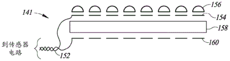
FIG. 8 is a schematic diagram illustrating a second example array of pressure sensors suitable for use with the present invention;
FIG. 9 is a schematic diagram illustrating a third example pressure sensor array suitable for use with the present invention;
FIG. 10 is a schematic diagram illustrating a fourth example array of pressure sensors suitable for use with the present invention;
FIG. 11A is a schematic diagram illustrating a first example sensor element in more detail;
FIG. 11B is a schematic diagram illustrating a second example sensor element in more detail;
FIG. 12 is a schematic diagram showing a top view of an example sensor array of the present invention;
FIG. 13 is a schematic diagram showing a bottom view of an example sensor array;
FIG. 14 is a schematic diagram showing a top view of another example sensor array of the present invention;
fig. 15 is a graph showing a relationship between the resistance and the force of the conductive film;
FIG. 16 is a schematic diagram showing an example voltage divider circuit for use with a sensor element;
FIG. 17 is a schematic diagram showing the connection of a plurality of sensor elements to a sensor circuit; and
fig. 18 is a schematic diagram illustrating an example front-end circuit coupled to a sensor element.
Detailed Description
In the following detailed description, numerous specific details are set forth in order to provide a thorough understanding of the invention. However, it will be understood by those skilled in the art that the present invention may be practiced without these specific details. In other instances, well-known methods, procedures, and components have not been described in detail so as not to obscure the present invention.
Among those benefits and improvements that have been disclosed, other objects and advantages of this invention will become apparent from the following description taken in conjunction with the accompanying drawings. Detailed embodiments of the present invention are disclosed herein; however, it is to be understood that the disclosed embodiments are merely illustrative of the invention that may be embodied in various forms. Furthermore, each of the examples given in connection with the various embodiments of the invention are intended to be illustrative, and not restrictive.
The subject matter regarded as the invention is particularly pointed out and distinctly claimed in the concluding portion of the specification. The invention, however, both as to organization and method of operation, together with objects, features, and advantages thereof, may best be understood by reference to the following detailed description when read with the accompanying drawings.
The drawings constitute a part of this specification and include illustrative embodiments of the present invention and illustrate various objects and features thereof. Furthermore, the figures are not necessarily to scale, some features may be exaggerated to show details of particular components. Moreover, any measurements, specifications, and the like shown in the figures are for purposes of illustration and not limitation. Therefore, specific structural and functional details disclosed herein are not to be interpreted as limiting, but merely as a representative basis for teaching one skilled in the art to variously employ the present invention. Further, where considered appropriate, reference numerals may be repeated among the figures to indicate corresponding or analogous elements.
Because the illustrated embodiments of the present invention may, for the most part, be implemented using electronic components and circuits known to those skilled in the art, details will not be explained in any greater extent than that considered necessary as illustrated, for the understanding and appreciation of the underlying concepts of the present invention and in order not to obfuscate or distract from the teachings of the present invention.
Any reference in the specification to a method should, with appropriate modification, be applied to a system capable of performing the method. Any reference in the specification to a system should, with appropriate modification, be applied to the method as capable of being performed by the system.
Throughout the specification and claims, the following terms take the meanings explicitly associated herein, unless the context clearly dictates otherwise. The phrases "in one embodiment," "in an example embodiment," and "in some embodiments," as used herein, do not necessarily refer to the same embodiment, although they may. Moreover, the phrases "in another embodiment," "in an alternative embodiment," and "in some other embodiments," as used herein, do not necessarily refer to a different embodiment, although it may. Thus, as described below, various embodiments of the invention may be readily combined without departing from the scope or spirit of the invention.
Further, as used herein, the term "or" is an inclusive "or" operator, and is equivalent to the term "and/or," unless the context clearly dictates otherwise. The term "based on" is not exclusive and allows for being based on additional factors not described, unless the context clearly dictates otherwise. In addition, throughout the specification, the meaning of "a", "an", and "the" include plural references. The meaning of "in. (in)" includes "in. (in)" and "on. (on)".
A schematic diagram illustrating a first view of an example wearable device of the present invention operable for measuring blood pressure of a user from the radial and/or ulnar arteries is shown in fig. 1. A schematic diagram illustrating a second view of an example wearable device of the present invention operable for measuring a user's blood pressure is shown in fig. 2. A schematic diagram illustrating a pressure sensor included within a wearable device and configured to sense pressure from the radial artery and/or the ulnar artery is shown in fig. 3.
Referring to fig. 1, 2 and 3, a wearable device (generally designated 10) includes: a display 16 (e.g., visible OLED, etc.) mounted in a housing 17 that houses a CPU, memory, wired and wireless communications, etc.; one or more buttons, switches or dials (dials) 22; a wristband (strap) 14 housing an array of pressure sensors 12, including one or more pressure sensors 24, 26 adapted to sense pressure of the radial artery 28 and/or the ulnar artery 30; one or more optical or other non-pressure sensors 18; and strap closure (strap closure), clasping (clasp), retaining, securing or locking mechanisms 20. The wristband strap has embedded pressure sensors thereon, and when the sensor array 12 is applied to at least one of the radial, ulnar and brachial arteries, the wristband will close against the wrist and then exert a moderate pressure thereon (i.e., significantly less than the systolic pressure but sufficient to sense pressure waves).
In one example, the wearable consumer product device 10 is a wearable multi-function electronic device that includes a variety of functions, such as timing, health monitoring, motion monitoring, medical monitoring, communication with a host device and/or cloud server, navigation, computing operations, and/or the like. These functions may include, but are not limited to: timing; monitoring physiological signals (e.g., heart rate, blood pressure, etc.) of the user and providing health-related information based on the signals; communicate (wired or wireless) with other electronic devices or services, which may be different types of devices having different functions; providing an alert to a user, which may include audio, tactile, visual, and/or other sensory outputs, any or all of which may be synchronized with one another; visually depicting data on a display; collecting data from one or more sensors that may be used to initiate, control, or modify the operation of the device; determining the location of a touch on the surface of the device and/or the magnitude of a force exerted on the device and using either or both as input; accepting voice input to control one or more functions; accepting tactile input to control one or more functions; capturing and transmitting an image; and the like.
The device 10 may take a variety of forms. In one example, the device is a wrist-worn electronic device. The device may include various types of form factors including wristbands, armbands, bracelets, jewelry, and the like.
A wearable consumer product is a product that can be worn by or otherwise secured to a user. It is noted that the user may wear the wearable consumer product in a variety of ways, for example around the wrist. In this case, the device includes a band or wristband that may be wrapped around the user's wrist to secure the device to the user's body. The device may include one or more other types of accessories including, for example, arm straps, sling straps (lanyard), waist straps, chest straps, and the like.
In one embodiment, the device includes a housing 17, the housing 17 carrying, enclosing, and supporting various components (including, for example, integrated circuit chips and other circuitry) both external and internal to provide computing and functional operations for the device. The components may be disposed outside of the housing, partially within the housing, through the housing, completely within the housing, etc. For example, the housing may include a cavity for holding the component inside, an aperture or window for providing access to the internal component, and various features for attaching other components. The housing may also be configured to form a water-resistant or waterproof shell. For example, the housing may be formed from a monolithic body, and the opening in the monolithic body may be configured to cooperate with other components to form a water-resistant or waterproof barrier. In another embodiment, the housing may not include a cavity, but rather be constructed of plastic into which the device electronics are molded.
Examples of components that may be included in a device include a processing unit, memory, display, sensor, biosensor, speaker, microphone, haptic actuator, accelerometer, gyroscope, battery, and so forth. In some cases, the device may have a small form factor. In this case, the components may be packaged in order to provide maximum functionality in a minimum amount of space. These components may also be configured to occupy a minimal amount of space, which may contribute to a small form factor for the device. Further, the integration and assembly of various components may be configured to enhance the reliability of the device.
The configuration of the housing can vary widely. For example, the housing may be formed from a variety of materials including plastic, rubber, wood, silicone, glass, ceramic, fiber composite, metal or metal alloy (e.g., stainless steel, aluminum), precious metal (e.g., gold, silver), or other suitable material or combination of materials.
Also in the embodiment shown, the wearable electronic device comprises a strap 14 or strap or other means for attachment to the arm 23 of the user. For example, the band may be configured to be attached to the body and provide a loop for securing to the wrist of the user. The strap may be integral with the housing or may be a separate part. If integral, the band may be a continuation of the housing. In some cases, the unitary band may be formed of the same material as the housing. If the strap is separate, the strap may be fixedly or releasably coupled to the housing. In both cases, the band may be formed of a similar or different material than the housing. In most cases, the band is formed of a flexible material (e.g., an elastomer) so that it can conform to the user's body. Further, the strap itself may be a single unitary component, or it may include attachment ends that provide the open and closed configurations. For example, the attachment end may represent a buckle or other similar attachment mechanism or device. This particular configuration allows the user to open the strap for placement on the arm and then close the strap to secure the strap and body to the arm. Many variations of the tape are possible. By way of example, they may be formed of rubber, silicone, leather, metal, mesh, hinges, and the like.
A high-level block diagram illustrating an example wearable electronic device incorporating a blood pressure measurement mechanism of the present invention is shown in fig. 4. By way of example, the apparatus 50 may correspond to the consumer product 10 shown in fig. 1, 2 and 3 described above. To the extent that various functions, operations, and structures are disclosed as part of device 50, incorporated into device 50, or performed by device 50, it is understood that various embodiments may omit any or all of these described functions, operations, and structures. Thus, different embodiments of the apparatus 50 may have some or all of the various functions, devices, physical features, modes and operating parameters discussed herein, or none at all.
The device 50 includes one or more processing units 52 configured to access a memory 56 having instructions stored thereon. The instructions or computer programs may be configured to perform one or more of the operations or functions described with respect to the device 50. For example, the instructions may be configured to control or coordinate operation of display 64, one or more input/output components (such as touch sensor 60, etc.), one or more communication channels 70, one or more sensors (such as bio-sensor 74 and non-bio-sensor 78), speaker 66, microphone 62, and/or one or more haptic feedback devices 68.
The processing unit 52 may be implemented as any electronic device capable of processing, receiving or transmitting data or instructions. For example, the processing unit may comprise one or more of the following: a microprocessor, a Central Processing Unit (CPU), an Application Specific Integrated Circuit (ASIC), a Digital Signal Processor (DSP), or a combination of these devices. As described herein, the term "processor" is meant to encompass a single processor or processing unit, a plurality of processors, a plurality of processing units, or other suitably configured one or more computing elements.
For example, a processor may include one or more general purpose CPU cores and optionally one or more special purpose cores (e.g., DSP cores, floating point, etc.). One or more general-purpose cores execute general-purpose opcodes, while special-purpose cores execute functions specific to their purpose.
The memory 56 includes Dynamic Random Access Memory (DRAM) or Extended Data Output (EDO) memory or other types of memory such as ROM, static RAM, flash and non-volatile static random access memory (NVSRAM), removable memory, bubble memory (bubble memory), the like, or a combination of any of the above. The memory stores electronic data that can be used by the device. For example, the memory may store electrical data or content, such as, for example, audio and video files, documents and applications, device settings and user preferences, timing and control signals, or data for various modules, data structures, or databases. The memory may be configured as any type of memory.
The display 64 is used to present visual or graphical output to the user. In some embodiments, the display comprises a graphical user interface generated using an operating system or software application executing on one or more processing units of the device. In one example, the display includes a graphical depiction similar to a watch dial or other timing device. In other examples, the display includes a graphical interface for email, text messaging, or other communication-oriented programs. The display may also present visual information corresponding to one of the other functional aspects of the device 50. For example, the display may include information corresponding to inputs of the biometric sensor 74, the non-biometric sensor 78, the force sensor 59, the touch sensor 60, and the like.
The input section 72 may include buttons, switches, dials, crowns (crown), and the like for accepting user input. Typically, the input component is configured to convert user-provided input into signals or instructions that can be accessed using instructions executing on the processor. In this example, the input component may include hardware (e.g., buttons, switches, crowns, and encoders) configured to receive user input that is operatively coupled to circuitry and firmware for generating signals or data that can be accessed using processor instructions. Each input component may include dedicated circuitry for generating signals or data, and additionally or alternatively, circuitry and firmware for generating signals or data that may be shared among multiple input components. In some cases, the input component generates user-provided feedback for the specialized input, which corresponds to a prompt or user interface object presented on the display 64. For example, the crown may be used to receive rotational input from a user, which may be translated into instructions for scrolling through a list or objects presented on the display. The input component may also generate user input for system level operation. For example, the input component may be configured to interact directly with hardware or firmware executing on the device for system level operations including, but not limited to, power on, power off, sleep, wake up, and do not disturb operations.
The speaker and microphone are also operatively coupled to a processor that may control the operation of the speaker and microphone. In some cases, the processor is configured to operate the speaker to produce sound output corresponding to an application or system level operation executing on the device 50. In some cases, the speaker is operably coupled to other modules including, for example, an input component 72 (e.g., a crown or button). In some embodiments, the device is configured to generate an audible output corresponding to the operation of the crown or button using the speaker. The microphone may be configured to produce an output or signal in response to the acoustic stimulus. For example, a microphone may be operatively coupled to the memory 56 and may be configured to record audio input, including human speech, music, or other sounds. In some cases, the microphone may be configured to receive a voice signal that may be interpreted as a voice command by the processor.
One or more communication channels 70 may include one or more wired and/or wireless interfaces adapted to provide communication between processor 52 and external devices, such as host device 120 (fig. 5). In general, one or more communication channels may be configured to transmit and receive data and/or signals that may be interpreted as instructions for execution on a processor. In some cases, the external device is part of an external communication network configured to exchange data with the wireless device. In general, the wireless interface may include, but is not limited to, radio frequency signals, optical signals, acoustic signals, and/or magnetic signals, and may be configured to operate over a wireless interface or protocol. Example wireless interfaces include a radio frequency cellular interface, a fiber optic interface, an acoustic interface, a bluetooth interface (e.g., bluetooth low energy, etc.), an infrared interface, a USB interface, a Wi-Fi interface, a TCP/IP interface, a network communication interface, or any common communication interface.
In some implementations, the one or more communication channels can include a dedicated wireless communication channel between the device and another user device (e.g., a mobile phone, a tablet, a computer, a host device, etc.). In some cases, the output, including the audio sound or visual display elements, is transmitted directly to another user device for output to the user. For example, an audible alert or visual warning may be transmitted to the user's mobile phone for output on the device. Similarly, one or more communication channels may be configured to receive user input provided on another user device. In one example, a user may control one or more operations on the device using a user interface on an external mobile phone, tablet, computer, or the like.
Further, the communication channel 70 may include a Near Field Communication (NFC) interface. The NFC interface may be used to identify the device and initiate a secure data connection, which may be used to authorize transactions, purchases, or conduct other forms of electronic commerce.
The device 50 also includes one or more biosensors 74 and non-biosensors 78. The non-biological sensors 78 may include one or more different sensors including devices and components configured to detect environmental conditions and/or other aspects of the operating environment. Examples include an Ambient Light Sensor (ALS), a proximity sensor, a temperature sensor, an atmospheric pressure sensor, a humidity sensor, and the like. Thus, the non-biological sensor 78 may also be used to calculate ambient temperature, air pressure, and/or water entering the device. In some embodiments, the non-biological sensors 78 may include one or more motion sensors for detecting motion and acceleration of the device. The one or more motion sensors may include one or more of the following: a tilt sensor 76, an accelerometer 80, a gyroscope 84, a magnetometer 86, or other type of inertial measurement device.
The motion sensor data may be used to monitor and detect changes in the motion of the device. The changes in linear and angular motion can be used to determine or estimate the orientation of the device relative to a known position or fixed reference. Sensor inputs generated from one or more motion sensors may also be used to track the user's motion. The user's motion may be used to facilitate navigation or map guidance functions of the device. Further, input related to the overall movement of the user may be used as a pedometer or activity meter, which may be stored and tracked over time to determine health metrics or other health-related information. Additionally, in some embodiments, sensor input from one or more motion sensors may be used to recognize motion gestures. For example, a motion sensor may be used to detect (within a predetermined confidence level of certainty) arm elevation or the position of the user's body.
The device 50 also includes one or more biosensors 74, which may include optical and/or electronic biometric (biometric) sensors that may be used to calculate one or more health metrics. One or more of the biosensors may include one or more pressure sensors 86 for measuring blood pressure, a photodetector and a light source for forming a photoplethysmography (PPG) sensor 88. One or more optical (e.g., PPG) sensors may be used to calculate various health metrics including, but not limited to, heart rate, respiration rate, blood oxygen level, blood volume estimation, blood pressure, or combinations thereof. One or more of the biosensors may also be configured to perform electrical measurements using one or more electrodes in contact with the user's body. Electrical sensors may be used to measure Electrocardiogram (ECG) characteristics, galvanic skin resistance (galvanic skin resistance), and other electrical characteristics of the user's body. Additionally or alternatively, one or more of the biosensors may be configured to measure body temperature, exposure to UV radiation, and other health-related information.
The device 50 may include a battery or other suitable power source 54 for storing power and providing power to other components of the device. The battery may be a rechargeable power source configured to provide power to the device when the device is worn by a user. The device may also be configured to recharge the battery using a wireless charging system. Thus, in some cases, a device may include a wireless power module 55 that may be configured to receive power from an external device or docking station (dock). The wireless power module may be configured to deliver power to a device component including a battery.
In some implementations, the device includes one or more receive inductive coils configured to cooperate with one or more transmit inductive coils located in the charging dock or other external device. Wireless charging systems allow for power delivery and/or wireless communication with devices without the use of external ports or terminal connections.
The wireless power module and the external charging station or docking station may also be configured to transfer data between the device and the base or host device. In some cases, the wireless power module may interface with a wireless charging station or docking station to provide authentication routines that can identify specific hardware, firmware, or software on the device to facilitate device maintenance or product updates.
The device 50 may include a force sensor 59 configured to detect and measure the magnitude of the force of a touch on the surface of the device. The output of the force sensor may be used to control various aspects of the device. For example, a force sensor may be used to control an aspect, such as a cursor or item selection on a user interface presented on a device display. Force sensors may also be used to control audio output, tactile output, and other functions of the device. Force sensors may also be used to distinguish between different types of input from a user. For example, a tap from the user may be interpreted as a scroll command and used to index or scroll through a list of items on the display. A more forceful touch from the user may be interpreted as a selection or confirmation of an item on the display.
The device 50 may also include a touch sensor 60 configured to detect and measure a touch location on the surface of the device. In some implementations, the touch sensor is a capacitance-based touch sensor disposed relative to a display or display stack (display stack) of the device. The touch sensor may be a separate, non-integrated sensor relative to the force sensor. In alternative embodiments, touch sensors may also be physically and/or logically integrated with force sensors to produce a combined output. Touch sensors may be used to control various aspects of a device, for example, to control aspects of a user interface presented on a display of the device, audio output, tactile output, and other functions of the device.
In some cases, the logical integration of the force sensors 59 and touch sensors 60 enhances the versatility or applicability of the device 50 by enabling a high-level user interface. For example, they may be combined to interpret a greater range of gestures and input commands than may be achieved, for example, using only touch input. For example, the force sensor may provide a magnitude of touch force, which may be used to distinguish two touch input commands having similar locations or gesture paths. The improved touch interface using both force sensors and touch sensors may be particularly advantageous when interpreting touch commands on relatively small area surfaces, such as a display screen or cover glass of a wearable electronic device.
A high-level block diagram illustrating an example blood pressure measurement device (e.g., a wearable device in communication with an optional host device) is shown in fig. 5. A blood pressure measurement device, generally designated 90, includes a control unit/processor 92 (including, inter alia, a blood pressure measurement processing block 93), a clock source 94 (e.g., a crystal oscillator), a display 96, a communication module 108, a memory 110, a power supply 112, one or more pressure sensors 98, a PPG sensor 100, and one or more motion sensors (e.g., a 3D micro-electromechanical systems (MEMS) accelerometer 102, a gyroscope 104, and/or a magnetometer 106). The host device, generally designated 120, includes a control unit or processor 122, a display 126, and a communication module 124. It is noted that the device 90 may be incorporated into a wearable device as shown in fig. 4 described in detail above.
It is noted that the one or more pressure sensors may include (1) a microelectromechanical system (MEMS) capacitive pressure sensor; (2) patch sensors applied to the brachial artery; (3) a pressure sensor array that simultaneously collects pressure data; (4) an array of pressure sensors operable for producing a single pressure measurement; (5) a pressure sensor array operable for producing a plurality of pressure measurements; and (6) an array of pressure sensors that are time-domain multiplexed based on the respective signal quality of each sensor.
In operation, the control unit is configured to receive data from a plurality of sources, process the data, and output waveforms, measurements, and telematics results (telematics). The one or more pressure sensors are adapted to sense pressure when pressed against a hand artery, such as the radial, ulnar or brachial artery. The display is adapted to display waveforms, measurements (e.g., blood pressure, heart rate, temperature, etc.), and telematics results (e.g., battery status). The power supply is adapted to provide power to various circuits and may include a battery (e.g., a lithium-ion or lithium-ion polymer rechargeable battery). The memory is used for storing programs and data. The device 90 may also include a photoplethysmography (PPG) sensor for independently measuring and synchronizing heart rate. The communication module is used to transmit data over a communication link 114, which may include a wired or wireless link. In one embodiment, the device transmits data when the link is continuously or intermittently available, while at other times the device stores the data in volatile or non-volatile (NV) memory.
In one embodiment, the blood pressure measurement device 90 may be connected to a host unit 120. The host device is configured to communicate with the blood pressure measurement device over link 114 using communication module 124. The control unit 122 is programmed to display information from the blood pressure measuring device 90 or to display information relating to the measurement values obtained (and optionally processed) by the blood pressure measuring device 90.
The wearable device of the present invention provides an array of pressure sensors with flexible properties and a biocompatible material interface between the sensors and the user's skin. In one embodiment, the pressure sensor array uses a (i.e., conductive) material (e.g., a Velostat or Linqstat conductive film) as a substrate and places the conductors in a suitable configuration, such as in an interdigitated or opposed configuration, to form a plurality of individual sensor elements. The characteristics of the Velostat and Linqstat conductive materials are that their resistance decreases when pressure is applied to them. The array also includes a mechanical interface disposed over the sensor elements for creating the sensor array. It is worth noting that this solution is cheaper, more flexible and has a more comfortable interface with respect to the skin.
Notably, Velostat and Linqstat are commercially available packaging materials made from polymer foil (polyolefin) impregnated with carbon black to make the material conductive. Velostat (formerly a 3M product) is available from Desco Industries, Inc. in the United states (address One Colgate Way, Canton, Mass. 02021). Linqstat is available from Caprinq Corporation of Canada (address 957Snowshoe Crescent-Orl e ans, Ottawa ON, K1C 2Y 3).
An advantage of the present invention is that it provides a cost-effective and non-invasive continuous blood pressure measuring device. By using off-the-shelf inexpensive technologies such as piezoresistive conductive membranes, the need for complex MEMS devices is avoided, while the advantages of physical flexibility and a comfortable skin interface are obtained.
A schematic diagram illustrating a side view of a wristband according to an embodiment of the invention is shown in fig. 6. The device, generally designated 130, includes a housing and display 134, a wrist band 138 and a pressure sensor array 131. The wristband 138 is configured to close around a skin surface 132 of a tubular extremity organ 136 (e.g., a finger, wrist, arm, or leg) containing a target blood vessel 133 (e.g., one of the brachial, radial, ulnar, femoral, metacarpophalangeal arteries, etc.) while applying moderate pressure (i.e., significantly less than systolic pressure in the blood vessel 142, but sufficient to sense pressure waves).
The pressure sensor array 131 can include several different embodiments. Four example embodiments are shown in fig. 7, 8, 9 and 10, which are described in more detail below with reference to fig. 6.
A schematic diagram illustrating a first example pressure sensor array suitable for use with the present invention is shown in fig. 7. The array of pressure sensors, generally designated 140, is configured to contact the organ 136 (fig. 6) when the wearable device 10 (fig. 1) is properly secured to the user. The gap between the wristband 138 (fig. 6), sensor array 140 and organ 136 is shown for clarity only, and is typically minimal or absent in a closer fit.
In one embodiment, the sensor 140 includes a resistive force sensing film or sheet 148 mounted on the wristband 138 and constructed of a piezoresistive conductive material (e.g., Velostat or Linqstat). Both materials are made of polymer foils impregnated with carbon black, which makes them electrically conductive. When pressure is applied to these materials, their electrical resistance decreases. To sense pressure from skin surface 132 and blood vessels 133, an array of interdigitated conductor pairs (referred to as "sensing elements" or "sensing element array") 150 is fabricated on the top or bottom surface of sheet 148 using any suitable well-known process, such as flexible Printed Circuit Board (PCB) technology, such that sensing elements 150 are printed on touch sheet 148. Each conductor has a pair of wires 144 from each sensor in the array 150. For each element in the sensor array 150, there is a respective mechanical protruding element 146 that serves to transmit or direct (i.e., focus) pressure from a surface above and in contact with it to the sensing elements in the sensing element array 150. Such elements may be constructed of hard materials (e.g., resins, plastics, cements, etc.), or softer materials such as gel polymers (e.g., Polydimethylsiloxane (PDMS), various other "silicones," etc.), or a combination of hard and softer materials.
When wristband 138 is closed snugly around organ 136, moderate pressure is applied to skin surface 132 and mechanical protruding elements 146 are coupled with skin 132. Preferably, the protruding elements are located substantially above the sensing elements, whether the sensing elements are located on the top or bottom surface of the piezoresistive wafer. As the blood pressure mechanical wave advances through the blood vessel 142, it couples through one or more mechanical protruding elements 146 through the piezoresistive sheet 148 into one or more sensing elements 150. The electrical resistance of the foil region where the mechanical pressure wave experiences strain is reduced. This is obtained by one or more elements 150 in the sensor array and transmitted to the sensor circuitry (not shown) via wires 144. The function of the sensor circuit is to convert the sensor signal into a blood pressure measurement by digital data processing of the processor.
A schematic diagram illustrating a second example pressure sensor array suitable for use with the present invention is shown in fig. 8. The array of pressure sensors, generally designated 141, is configured to contact the organ 136 (fig. 6) when the wearable device 10 (fig. 1) is properly secured to the user. In one embodiment, a resistive force sensing sheet (i.e., a conductive sheet) 158 is mounted on the wristband 138 and is constructed of a piezoresistive material (e.g., Velostat or Linqstat). To sense pressure from skin surface 132 and blood vessels 133, two opposing conductor arrays 160 and 154 (referred to as "sensing elements" or "sensing element arrays") are fabricated on both sides of sheet 158 using any suitable well-known process (e.g., flexible Printed Circuit Board (PCB) technology) such that conductive pairs 160, 154 contact sheet 158. The shape of each conductor is not critical as long as the desired force/resistance relationship is achieved for the particular implementation. Preferably, uninterrupted (i.e. continuous) elements are used on both sides of the sensing foil. An example of a round (button) -shaped conductor is shown in fig. 11B described below. It is noted that generally, interdigital conductive fingers are not used, since it is desirable to obtain as much force-dependent resistance as possible from the sensing foil. Each conductor pair has a pair of wires 152 connected thereto. For each conductor pair 160, 154 there is a respective mechanically protruding element 156, which mechanically protruding element 156 serves to direct pressure from the surface above it onto the sensing elements in the array of sensing elements. Such elements may be constructed of hard materials (resin, plastic, cement, etc.), or of softer materials such as gel polymers (e.g., Polydimethylsiloxane (PDMS), various other "silicones", etc.), or a combination of hard and softer materials.
When the wristband 138 is closed snugly around the organ 136, moderate pressure is applied to the skin surface 132 and the mechanical protruding elements 156 couple with the skin 132. As the blood pressure mechanical wave progresses through the blood vessel 133, it couples through one or more mechanical protruding elements 156 into one or more of the sensing element conductive pairs 154 and 160 and through the piezoresistive sheet 158. The region of the foil where the mechanical pressure wave experiences strain will decrease in its electrical resistance. This is obtained by one or more elements in the sensor array conductive pair 160 and 154 and transmitted to the sensor circuitry (not shown) via the conductive line 152. The function of the sensor circuit is to convert the sensor signal into a blood pressure measurement by digital data processing of the processor.
A schematic diagram illustrating a third example pressure sensor array suitable for use with the present invention is shown in fig. 9. The array of pressure sensors, generally designated 142, is configured to contact the organ 136 (fig. 6) when the wearable device 10 (fig. 1) is properly secured to the user. In one embodiment, a resistive force sensing sheet (i.e., a conductive sheet) 168 is mounted on the wristband 138 and is constructed of a piezoresistive material (e.g., Velostat or Linqstat). The pressure sensor array 142 includes a plurality of sensor elements 164. Each element 164 within the sensor array includes a set of interdigitated fingers 166 fabricated on the top or bottom surface of the sensing sheet, a pair of wires 162 connected thereto, a rigid material tubular cylinder 172 (hereinafter referred to as a "chimney" or "meniscus") and a soft material (e.g., silicone (PDMS), PU) bump 170 dispensed on top of the chimney 172 and completely filling the chimney. When the wristband 138 is closed snugly around the skin surface 132, the bumps in the sensor array 142 contact the skin and at least one of them will be in proximity to the target blood vessel 142. It is noted that it is preferred that the bumps and cylinders are located substantially above the sensing element, whether they are located on the top or bottom surface of the piezoresistive wafer. The pulse wave from the blood vessel 142 travels through its adjacent ridge 170, causing strain to the soft material. Because the volume in the chimney 172 is substantially fixed and static, the pressure waveform is transmitted (i.e., directed) directly to the resistive force sheet 168, and its resistance change is picked up by the conductor 166. An advantage of this configuration is that while the pressure waves are transmitted through a biocompatible soft material (e.g., silicone (PDMS), PU, etc.) that can be worn for long periods of time (at least several hours), most of the force is transmitted directly to the piezoresistive sheet 168 and the sensor without being dispersed in the material causing deformation.
A schematic diagram illustrating a fourth example pressure sensor array suitable for use with the present invention is shown in fig. 10. The array of pressure sensors (generally designated 143) is configured to contact the organ 136 (fig. 6) when the wearable device 10 (fig. 1) is properly secured to the user. In one embodiment, a resistive force sensing sheet 186 is mounted on the wristband 138 and is constructed of a piezoresistive material (e.g., Velostat or Linqstat). The pressure sensor array 143 includes a plurality of sensor elements 180. Each element within the array 143 includes a set of opposing conductors 182 and 184, a pair of wires 178 connected thereto, a rigid material tubular cylinder 176 (hereinafter referred to as a "chimney" or "meniscus"), and a soft material (e.g., silicone (PDMS), PU) ridge 174 dispensed on top of and completely filling the chimney 176. It is noted that the shape of each conductor is not critical, as long as the desired force/resistance relationship is achieved for the particular implementation. Preferably, uninterrupted (i.e. continuous) elements are used on both sides of the sensing foil. An example of a round (button) -shaped conductor is shown in fig. 11B described below. It is noted that generally, interdigital conductive fingers are not used, since it is desirable to obtain as much force-dependent resistance from the sensing foil as possible.
When the wristband 138 is closed snugly around the skin surface 132, the ridges in the array 143 contact the skin and at least one of them will be proximate the target blood vessel 133. The pulse wave from the blood vessel 133 travels through its adjacent ridges, causing strain to the soft material. Because the volume in the chimney 176 is constant, the pressure waveform is transmitted directly to the resistive force sheet, and its resistance change is picked up by the conductors 182 and 184. The advantage of this approach is that although the pressure waves are transmitted through a biocompatible soft material, such as silicone (PDMS) or PU, and the soft material can be worn for long periods of time (at least several hours), most of the force is transmitted directly to the piezoresistive sheet 186 and the sensor without being dispersed in the material causing deformation.
A schematic diagram illustrating a first example sensor element in more detail is shown in fig. 11A. The sensor elements, generally designated 192, are suitable for use as sensor elements in sensor arrays 140 (fig. 7) and 142 (fig. 9). Sensor 192 includes a resistive force sensing sheet 196 made of a piezoresistive material (e.g., Velostat or Linqstat), a first interdigital conductive element 194 printed on one side of sheet 196 and connected to terminal 191, and a second interdigital conductive element 198 printed on the same side of sheet 196 and connected to terminal 190. Terminals 190 and 191 are both coupled to the sensor circuit. It is appreciated that the sensor elements are not limited to interdigitated conductive elements, but may include any suitable pair of conductors that are spaced apart such that upon application of pressure, a change in resistance in the resistive force sensing sheet may be detected by the sensor circuitry.
A schematic diagram illustrating a second example sensor element in more detail is shown in fig. 11B. This second example is suitable for use as a sensor element in sensor arrays 141 (fig. 8) and 143 (fig. 10). In this second example of a sensor element, generally designated 200, a first conductive element 204 is printed on one side of a resistive force sensing sheet 206 made of a piezoresistive material (such as Velostat or Linqstat) and connected to one terminal 208. A second conductive element 212 is printed on the opposite side of the sheet and is connected to the second terminal 210. Terminals 208 and 210 are both coupled to the sensor circuit. As noted above, the shape of each conductor is not critical, so long as the desired force/resistance relationship is achieved for the particular implementation. Preferably, uninterrupted (i.e. continuous) elements are used on both sides of the sensing foil.
A schematic diagram illustrating a top view of an example sensor array of the present invention is shown in fig. 12. The illustrated array is suitable for use in sensor arrays 140 (fig. 7) and 141 (fig. 8). The wristband 272 is configured to snugly close around a skin surface of a tubular extremity organ (e.g., a finger, wrist, arm, leg, etc.) containing a target blood vessel (e.g., one of the brachial, radial, ulnar, femoral, metacarpophalangeal arteries, etc.) while applying moderate pressure. The sensor array 270 includes piezoresistive sensors, such as a Velostat or Linqstat material 276 secured to a wristband 272. The sensor array includes a plurality of protruding mechanical elements 274 secured to a piezoresistive sheet 276 using any suitable well-known fastening mechanism, such as adhesive, glue, etc. As described above, each protruding mechanical element 274 serves to direct pressure from its top surface in contact with the user to the sensing element coupled to its bottom surface. Each element in the array of protruding mechanical elements includes a pair of conductors (not shown) located thereunder, with a pair of wires connected thereto. The pair of wires is coupled to the sensor circuit for signal processing.
A schematic diagram illustrating a bottom view of an example sensor array is shown in fig. 13. There is shown a bottom view of a sensor array 226 comprising a piezoresistive sheet 224 according to a first embodiment of the invention. The wristband is removed and the bottom of the piezoresistive sheet 224 is visible. For example, sensor elements 140 and 142 of fig. 7 and 9, respectively, are shown.
The piezoresistive sheet 224 includes an array of interdigital conductive elements 218 secured thereto. Each element includes two sets of interdigitated fingers 216 and 220. The fingers of each element in the array are made close to each other but not short-circuited so that any current flowing through one side must pass through the piezoresistive sheet 224 in order to reach the other side. The interdigital fingers 216 and 220 are connected to the rest of the system by a set of wires 222. Since the conductivity of the finger sets 216 and 220 and the wires 222 is much higher than the conductivity of the piezoresistive sheet 224, the resistance measured between the wires 222 is primarily determined by the resistivity of the local areas in the sheet 224. This allows strain waves (i.e., pressure waves) passing through the area of the sheet surrounded by the finger sets 216 and 220 to be detected. Furthermore, it allows reasonably good separation between the various elements, as any area of the sheet 224 away from the immediate vicinity of the conductors 216 and 220 will exhibit a much higher resistance relative to the fingers than its vicinity.
A schematic diagram illustrating a top view of another example sensor array of the present invention is shown in fig. 14. The sensor array may be used in array 142 and array 143 of fig. 9 and 10, respectively. The wristband 238 is intended for snug closure around the skin surface of a tubular extremity organ (e.g., a finger, wrist, arm, leg, etc.) containing a target blood vessel (e.g., one of the brachial, radial, ulnar, femoral, metacarpophalangeal arteries, etc.) while applying moderate pressure. A flexible piezoresistive sheet 234 is secured to a wristband 238 and an array of sensor elements is secured to the sheet 234. Each element 231 in the array contains a pair of wires 230 from a pair of conductors (not shown), a tubular element (chimney) 236 made of a hard material (e.g., metal, plastic, etc.), and a bump 232 of soft material dispensed thereon. It is noted that although the sensor array is shown here as a rectangle, it should be appreciated that a person skilled in the art may construct sensor arrays having many other shapes (e.g., linear, polygonal, diagonal, one-dimensional, two-dimensional, etc.).
As described above, the pressure sensor of the present invention utilizes commercially available pressure sensitive materials that contain piezoresistive materials to construct a sensor for measuring blood pressure. Piezoresistive materials are those materials that change their resistance due to deformation, typically caused by an applied force. As shown in fig. 15, the relationship between the applied force on the piezoresistive material and the change in resistance is inversely proportional. The resistance of a material is on the order of mega ohms when no force is applied, and decreases to the kilo-ohm range or less as the applied force increases.
The resistance of the piezoresistive material between the electrical contacts is described by the resistance-force relationship shown below.

Where ρ is the resistivity of the contact surface, F is the normal force applied to the contact surface, and K is a function of the roughness and elastic properties of the surface.
In one embodiment, the resistance of the sensor may be converted to a voltage signal using a voltage divider circuit. An example circuit is shown in fig. 16. The circuit, generally designated 380, includes a voltage divider in which a sensor R382 is placed in contact with a fixed resistor RLAre connected in series. The voltage measured at the sensor-resistor junction is obtained by applying ohm's law, as shown below.

Wherein R isLIs to complete the resistance, V, of the voltage dividerInput deviceIs input power applied to the sensorPressure (usually V)CC),VOutput ofIs the output of the voltage divider. In view of equations 1 and 2, the voltage-force relationship is given below.

It is noted that in one embodiment, a linear response may be obtained by connecting the sensor resistor 382 between a voltage source and the input of the current-to-voltage converter (i.e., a virtual ground), thereby obtaining a voltage output proportional to the piezoresistive sensor resistance.
A schematic diagram illustrating the connection of a plurality of sensor elements to a sensor circuit is shown in fig. 17. A plurality of N sensors 240(N being a positive integer greater than zero) are coupled to a corresponding plurality of N sensor circuits 242. The wire pairs from each sensor element are connected to a separate sensor circuit for amplifying and optionally filtering the signal from each sensor element. The signal from each sensor is digitized and an output 244 is generated. The N output signals are input to a processor for performing a Blood Pressure (BP) measurement process and generating blood pressure measurements (systolic and diastolic) that are presented to the user. It is noted that the sensor elements may comprise any of the sensor elements described above, and may be part of any type of sensor array such as described above. It is to be noted that, depending on the embodiment, the signals from the sensor elements may be fed into one or more sensor circuits capable of processing a plurality of signals. Alternatively, each sensor element may have its own corresponding sensor circuit.
A schematic diagram illustrating an example front-end circuit coupled to a sensor element is shown in fig. 18. The circuit, generally designated 350, includes a supply voltage (V) from a voltage sourceCC)300 and ground 302 which serves as a reference point for the circuit. A bias circuit (e.g., a resistive divider, a bandgap or Low Dropout (LDO) regulator) 304 at VCCGenerating a bias voltage V between the output terminal and groundBiasing330. Bias voltages respectively connected to the operational amplifiersPositive input ends 356 and 358 of the devices 306 and 308. One terminal 314 of an equivalent resistance 324 of one of the sensor elements printed on the piezoresistive sheet is connected to VCCAnd the other terminal 312 is connected to the negative input 354 of the operational amplifier 306. The output 352 of the operational amplifier 306 passes through a feedback resistor R f316 is connected to its negative input terminal 354, thereby creating an inverting transconductance amplifier. The voltage applied to the equivalent resistor 324 is converted to a current due to the virtual ground between pins 356 and 354, and the current is almost completely transferred to the feedback resistor R due to the high input impedance of the operational amplifier 306f 316。
The value of this current multiplied by resistor 316 is the resultant voltage, minus the offset voltage and appearing on output pin 352, which current flows through resistor 316. Operational amplifier 308 and its adjacent passive components R2 318、R 1320 and C 1322 implementing a low pass anti-aliasing filter using a resistor R 2318 and the virtual ground between the input terminals 358 and 364 convert the voltage at the output node 352 to a current. This current is almost entirely introduced into the resistor R connected in parallel between the output 370 of the operational amplifier 308 and its negative input 3641320 and a capacitor C 1322. The output of the operational amplifier 308 is input to an analog-to-digital converter (ADC)310, which converts it to a stream of digital samples, the output of the operational amplifier 308 providing the inverse (1/R) of the resistance of the equivalent resistor 324Sensor with a sensor element) A scaled and biased low pass filtered voltage. It is to be noted that 1/RSensor with a sensor elementApproximately proportional to the force exerted on the piezoresistive sheet.
The digital output signal 311 is input to a processor for subsequent blood pressure measurement processing to produce blood pressure measurements (systolic and diastolic) that are presented to the user.
Any arrangement of components to achieve the same functionality is effectively "associated" such that the desired functionality is achieved. Hence, any two components herein combined to achieve a particular functionality can be seen as "associated with" each other such that the desired functionality is achieved, irrespective of architectures or intermedial components. Likewise, any two components so associated can also be viewed as being "operably connected," or "operably coupled," to each other to achieve the desired functionality.
Further, those skilled in the art will recognize that the boundaries between the above described operations merely illustrative. Multiple operations may be combined into a single operation, single operations may be distributed in additional operations, and operations may be performed at least partially overlapping in time. Moreover, alternative embodiments may include multiple instances of a particular operation, and the order of operations may be altered in various other embodiments.
The terminology used herein is for the purpose of describing particular embodiments only and is not intended to be limiting of the invention. As used herein, the singular forms "a", "an", and "the" are intended to include the plural forms as well, unless the context clearly indicates otherwise. It will be further understood that the terms "comprises" and/or "comprising," when used in this specification, specify the presence of stated features, integers, steps, operations, elements, and/or components, but do not preclude the presence or addition of one or more other features, integers, steps, operations, elements, components, and/or groups thereof.
In the claims, any reference signs placed between parentheses shall not be construed as limiting the claim. The use of introductory phrases such as "at least one" and "one or more" in the claims should not be construed to imply that the introduction of another claim element by the indefinite articles "a" or "an" limits any particular claim containing such introduced claim element to inventions containing only one such element, even when the same claim includes the introductory phrases "one or more" or "at least one" and indefinite articles such as "a" or "an"). The same holds true for the use of definite articles. Unless otherwise specified, terms such as "first," "second," and the like are used to arbitrarily distinguish between the elements such terms describe. Thus, these terms are not necessarily intended to indicate temporal or other prioritization of such elements. The mere fact that certain measures are recited in mutually different dependent claims does not indicate that a combination of these measures cannot be used to advantage.
The corresponding structures, materials, acts, and equivalents of all means or step plus function elements in the claims below are intended to include any structure, material, or act for performing the function in combination with other claimed elements as specifically claimed. The description of the present invention has been presented for purposes of illustration and description, but is not intended to be exhaustive or limited to the invention in the form disclosed. Since numerous modifications and variations will readily occur to those skilled in the art, it is not desired to limit the invention to the limited number of embodiments disclosed herein. It is therefore to be understood that all suitable variations, modifications and equivalents may be resorted to, falling within the spirit and scope of the invention. The embodiment was chosen and described in order to best explain the principles of the invention and the practical application, and to enable others of ordinary skill in the art to understand the invention for various embodiments with various modifications as are suited to the particular use contemplated.
Aspects of the disclosure may be implemented in one or more of the following embodiments:
1) a sensor for blood pressure signal acquisition, comprising:
a substrate having a top surface and a bottom surface, the substrate comprising a resistive, electrically conductive force sensing film;
a mechanical element coupled to the top surface of the sensing diaphragm, the mechanical element operable to transfer pressure from a top surface of the mechanical element to the sensing diaphragm when in contact with a user; and
a pair of conductive elements secured to one of the top or bottom surfaces of the sensing diaphragm, the pair of conductive elements being spaced apart such that a change in resistance of the sensing diaphragm can be detected upon application of pressure to the mechanical element.
2) The sensor of 1), wherein the sensing film comprises a piezoresistive conductive film, the resistance of which decreases when pressure is applied to the piezoresistive conductive film.
3) The sensor of 1), wherein the sensing membrane comprises at least one of a Velostat conductive membrane and a Linqstat conductive membrane.
4) The sensor of 1), wherein the mechanical element comprises at least one of a hard material and a soft material.
5) The sensor of 4), wherein the hard material comprises at least one of a resin, a plastic, a cement.
6) The sensor of 4), wherein the soft material comprises at least one of a gel, a polymer, polydimethylsiloxane, and silicone (PDMS).
7) The sensor of 1), wherein the mechanical element comprises a relatively hard cylinder and a relatively soft material filling the cylinder, the cylinder operable to direct pressure waves from a user through the soft material to the sensing diaphragm.
8) The sensor of 1), wherein the pair of conductive elements comprises first and second interdigitated conductive elements.
9) The sensor of 8), wherein the interdigital first and second conductive elements are printed on the bottom surface of the sensing membrane.
10) The sensor of 1), further comprising a sensor circuit coupled to the pair of conductive elements and operable to generate a digital signal as a function of pressure applied to the mechanical element.
11) A sensor for blood pressure signal acquisition, comprising:
a substrate having a top surface and a bottom surface, the substrate comprising a resistive, electrically conductive force sensing film;
a first conductive element secured to the top surface of the sensing membrane;
a mechanical element coupled to the first conductive element, the mechanical element operable for transmitting pressure from a top surface of the mechanical element to the sensing diaphragm when in contact with a user;
a second conductive element secured to the bottom surface of the sensing diaphragm, the first conductive element and the second conductive element being spaced apart such that a change in resistance of the sensing diaphragm can be detected upon application of pressure to the mechanical element.
12) The sensor of claim 11), wherein the sensing film comprises a piezoresistive conductive film whose resistance decreases when pressure is applied to the piezoresistive conductive film.
13) The sensor of 11), wherein the sensing membrane comprises at least one of a Velostat conductive membrane and a Linqstat conductive membrane.
14) The sensor of 11), wherein the mechanical element comprises at least one of a hard material and a soft material.
15) The sensor of 14), wherein the hard material comprises at least one of a resin, a plastic, a cement.
16) The sensor of 14), wherein the soft material comprises at least one of a gel, a polymer, polydimethylsiloxane, and silicone (PDMS).
17) The sensor of 11), wherein the mechanical element comprises a relatively hard cylinder and a relatively soft material filling the cylinder, the cylinder operable to direct pressure waves from a user through the soft material to the sensing diaphragm.
18) The sensor of claim 11), wherein the first and second conductive elements comprise finger-shaped first and second conductive elements.
19) The sensor of 18), wherein the finger-shaped first and second conductive elements are printed on the top and bottom surfaces of the sensing membrane, respectively.
20) The sensor of claim 11), further comprising a sensor circuit coupled to the first and second conductive elements and operable to generate a digital signal as a function of pressure applied to the mechanical element.
21) A wearable device for measuring blood pressure of a user, comprising:
a housing;
a display mounted in the housing;
a wrist band coupled to the housing;
a processor coupled to a memory;
at least one sensor array comprising a plurality of sensing elements coupled to the sensor circuitry and operable for acquiring blood pressure signals;
each sensing element includes:
a substrate having a top surface and a bottom surface, the substrate comprising a resistive, electrically conductive force sensing film;
a mechanical element coupled to the top surface of the sensing diaphragm, the mechanical element operable to transfer pressure from a top surface of the mechanical element to the sensing diaphragm when in contact with a user; and
a first conductive element and a second conductive element secured to the sensing diaphragm, the first and second conductive elements being spaced apart such that a change in resistance of the sensing diaphragm can be detected upon application of pressure to the mechanical element.
22) The wearable device of 21), wherein the sensing membrane comprises at least one of a Velostat conductive membrane and a Linqstat conductive membrane.
23) The wearable device of 21), wherein the mechanical element comprises a relatively hard cylinder and a relatively soft material filling the cylinder, the cylinder operable to direct pressure waves from a user to the sensing membrane through the soft material.
24) The wearable device of 21), wherein the first conductive element is printed on the top surface of the sensing membrane and the second conductive element is printed on the bottom surface of the sensing membrane.
25) The wearable device of 21), wherein the first and second conductive elements are printed as a pair of interdigitated fingers on one of the top or bottom surfaces of the sensing membrane.
Claims (22)
1. A sensor for blood pressure signal acquisition, comprising:
a substrate having a top surface and a bottom surface, the substrate comprising a resistive, electrically conductive force sensing film;
a mechanical element coupled to the top surface of the sensing diaphragm, the mechanical element operable to transfer pressure from a top surface of the mechanical element to the sensing diaphragm when in contact with a user; and
a pair of conductive elements secured to one of the top or bottom surfaces of the sensing diaphragm, the pair of conductive elements being spaced apart such that a change in resistance of the sensing diaphragm can be detected upon application of pressure to the mechanical element,
wherein the mechanical element comprises a relatively hard cylinder and a relatively soft material filling the cylinder, the cylinder being operable for directing pressure waves from a user through the soft material to the sensing diaphragm.
2. The sensor of claim 1, wherein the sensing film comprises a piezoresistive conductive film whose resistance decreases when pressure is applied to the piezoresistive conductive film.
3. The sensor of claim 1, wherein the sensing membrane comprises at least one of a Velostat conductive membrane and a Linqstat conductive membrane.
4. The sensor of claim 1, wherein the mechanical element comprises at least one of a hard material and a soft material.
5. The sensor of claim 4, wherein the hard material comprises at least one of a resin, a plastic, a cement.
6. The sensor of claim 4, wherein the soft material comprises at least one of a gel, a polymer, Polydimethylsiloxane (PDMS), and silicone.
7. The sensor of claim 1, wherein the pair of conductive elements comprises first and second interdigitated conductive elements.
8. The sensor of claim 7, wherein the interdigitated first and second conductive elements are printed on the bottom surface of the sensing membrane.
9. The sensor of claim 1, further comprising a sensor circuit coupled to the pair of conductive elements and operable to generate a digital signal as a function of pressure applied to the mechanical element.
10. A sensor for blood pressure signal acquisition, comprising:
a substrate having a top surface and a bottom surface, the substrate comprising a resistive, electrically conductive force sensing film;
a first conductive element secured to the top surface of the sensing membrane;
a mechanical element coupled to the first conductive element, the mechanical element operable for transmitting pressure from a top surface of the mechanical element to the sensing diaphragm when in contact with a user;
a second conductive element secured to the bottom surface of the sensing diaphragm, the first conductive element and the second conductive element being spaced apart such that a change in resistance of the sensing diaphragm can be detected upon application of pressure to the mechanical element,
wherein the mechanical element comprises a relatively hard cylinder and a relatively soft material filling the cylinder, the cylinder being operable for directing pressure waves from a user through the soft material to the sensing diaphragm.
11. The sensor of claim 10, wherein the sensing film comprises a piezoresistive conductive film whose resistance decreases when pressure is applied to the piezoresistive conductive film.
12. The sensor of claim 10, wherein the sensing membrane comprises at least one of a Velostat conductive membrane and a Linqstat conductive membrane.
13. The sensor of claim 10, wherein the mechanical element comprises at least one of a hard material and a soft material.
14. The sensor of claim 13, wherein the hard material comprises at least one of a resin, a plastic, a cement.
15. The sensor of claim 13, wherein the soft material comprises at least one of a gel, a polymer, Polydimethylsiloxane (PDMS), and silicone.
16. The sensor of claim 10, wherein the first and second conductive elements comprise finger-shaped first and second conductive elements.
17. The sensor of claim 16, wherein the finger-shaped first and second conductive elements are printed on the top and bottom surfaces of the sensing membrane, respectively.
18. The sensor of claim 10, further comprising a sensor circuit coupled to the first and second conductive elements and operable to generate a digital signal as a function of pressure applied to the mechanical element.
19. A wearable device for measuring blood pressure of a user, comprising:
a housing;
a display mounted in the housing;
a wrist band coupled to the housing;
a processor coupled to a memory;
at least one sensor array comprising a plurality of sensing elements coupled to the sensor circuitry and operable for acquiring blood pressure signals;
each sensing element includes:
a substrate having a top surface and a bottom surface, the substrate comprising a resistive, electrically conductive force sensing film;
a mechanical element coupled to the top surface of the sensing diaphragm, the mechanical element operable to transfer pressure from a top surface of the mechanical element to the sensing diaphragm when in contact with a user; and
a first conductive element and a second conductive element secured to the sensing diaphragm, the first and second conductive elements being spaced apart such that a change in resistance of the sensing diaphragm can be detected upon application of pressure to the mechanical element,
wherein the mechanical element comprises a relatively hard cylinder and a relatively soft material filling the cylinder, the cylinder being operable for directing pressure waves from a user through the soft material to the sensing diaphragm.
20. The wearable device of claim 19, wherein the sensing membrane comprises at least one of a Velostat conductive membrane and a Linqstat conductive membrane.
21. The wearable device of claim 19, wherein the first conductive element is printed on the top surface of the sensing membrane and the second conductive element is printed on the bottom surface of the sensing membrane.
22. The wearable device of claim 19, wherein the first and second conductive elements are printed as a pair of interdigitated fingers on one of the top or bottom surfaces of the sensing membrane.
Applications Claiming Priority (5)
| Application Number | Priority Date | Filing Date | Title |
|---|---|---|---|
| US201762442189P | 2017-01-04 | 2017-01-04 | |
| US62/442,189 | 2017-01-04 | ||
| US15/827,493 US11000193B2 (en) | 2017-01-04 | 2017-11-30 | Blood pressure measurement system using force resistive sensor array |
| US15/827,493 | 2017-11-30 | ||
| PCT/IB2017/058419 WO2018127773A1 (en) | 2017-01-04 | 2017-12-27 | Blood pressure measurement system using force resistive sensor array |
Publications (2)
| Publication Number | Publication Date |
|---|---|
| CN110383021A CN110383021A (en) | 2019-10-25 |
| CN110383021B true CN110383021B (en) | 2021-07-20 |
Family
ID=62709134
Family Applications (1)
| Application Number | Title | Priority Date | Filing Date |
|---|---|---|---|
| CN201780087901.0A Active CN110383021B (en) | 2017-01-04 | 2017-12-27 | Blood pressure measurement system using resistive force sensor array |
Country Status (8)
| Country | Link |
|---|---|
| US (1) | US11000193B2 (en) |
| EP (1) | EP3566036B1 (en) |
| JP (1) | JP7338830B2 (en) |
| KR (1) | KR20190104374A (en) |
| CN (1) | CN110383021B (en) |
| CA (1) | CA3048964A1 (en) |
| ES (1) | ES2965856T3 (en) |
| WO (1) | WO2018127773A1 (en) |
Families Citing this family (36)
| Publication number | Priority date | Publication date | Assignee | Title |
|---|---|---|---|---|
| EP3514665A1 (en) | 2013-08-09 | 2019-07-24 | Apple Inc. | Tactile switch for an electronic device |
| WO2015122885A1 (en) | 2014-02-12 | 2015-08-20 | Bodhi Technology Ventures Llc | Rejection of false turns of rotary inputs for electronic devices |
| US10599101B2 (en) | 2014-09-02 | 2020-03-24 | Apple Inc. | Wearable electronic device |
| WO2016144919A1 (en) | 2015-03-08 | 2016-09-15 | Apple Inc. | Compressible seal for rotatable and translatable input mechanisms |
| US10335045B2 (en) | 2016-06-24 | 2019-07-02 | Universita Degli Studi Di Trento | Self-adaptive matrix completion for heart rate estimation from face videos under realistic conditions |
| US10061399B2 (en) | 2016-07-15 | 2018-08-28 | Apple Inc. | Capacitive gap sensor ring for an input device |
| US11832923B2 (en) | 2016-12-21 | 2023-12-05 | IdaHealth, Inc. | Device for monitoring blood flow |
| BE1024423B1 (en) | 2016-12-21 | 2018-02-13 | Idahealth Inc | Equipment for monitoring blood and respiratory flows |
| CN111107891A (en) * | 2017-07-17 | 2020-05-05 | 利弗梅特里克(医疗)股份公司 | Method and system for ventricular assist device adjustment using a wearable device |
| US10962935B1 (en) | 2017-07-18 | 2021-03-30 | Apple Inc. | Tri-axis force sensor |
| US10914583B2 (en) * | 2018-02-20 | 2021-02-09 | Analog Devices, Inc. | Sense amplifiers for gyroscopes and related systems and methods |
| US10974019B2 (en) * | 2018-04-16 | 2021-04-13 | Pulsewear Llc | System for delivering ultra-low frequency (ULF), variable-intensity, non-vibratory tactile stimuli for regulating physiological processes, and modulating mental states |
| US11360440B2 (en) | 2018-06-25 | 2022-06-14 | Apple Inc. | Crown for an electronic watch |
| US11561515B2 (en) | 2018-08-02 | 2023-01-24 | Apple Inc. | Crown for an electronic watch |
| CN109222920B (en) * | 2018-08-27 | 2021-04-13 | 上海市静安区精神卫生中心 | Mental disease patient remote monitoring system suitable for doctor to make follow-up visit diagnosis and treatment plan |
| CN209625187U (en) | 2018-08-30 | 2019-11-12 | 苹果公司 | Electronic watch and electronic equipment |
| KR102677448B1 (en) | 2018-11-13 | 2024-06-20 | 삼성전자주식회사 | Electronic device, method for estimating bio-information using the same |
| US20200196878A1 (en) * | 2018-12-19 | 2020-06-25 | Livemetric (Medical) S.A. | System and method for blood pressure monitoring with subject awareness information |
| US11194299B1 (en) | 2019-02-12 | 2021-12-07 | Apple Inc. | Variable frictional feedback device for a digital crown of an electronic watch |
| CN110123275A (en) * | 2019-05-08 | 2019-08-16 | 深圳前海达闼云端智能科技有限公司 | Artery position detection device and method |
| CN112205970A (en) * | 2019-07-10 | 2021-01-12 | 天津理工大学 | Array sensor and preparation method and application thereof |
| GB2589553B (en) * | 2019-10-09 | 2024-03-13 | Life Meter Srl | Pulse oximetry methods, devices and systems |
| KR20210129915A (en) | 2020-04-21 | 2021-10-29 | 삼성전자주식회사 | Module for measuring bio information |
| US11550268B2 (en) | 2020-06-02 | 2023-01-10 | Apple Inc. | Switch module for electronic crown assembly |
| KR102374658B1 (en) * | 2020-06-15 | 2022-03-16 | 전남대학교산학협력단 | Wearable blood pressure measuring device with multi-array pressure sensors |
| WO2022035430A1 (en) * | 2020-08-13 | 2022-02-17 | IdaHealth, Inc. | Device for monitoring blood flow |
| CN112129431B (en) * | 2020-09-11 | 2022-04-05 | 合肥工业大学 | PVDF sensor array structure based on wrist and performance testing device thereof |
| CN112525392B (en) * | 2020-11-05 | 2023-03-24 | 青岛大学 | Pressure sensing intelligent fabric and preparation method and application thereof |
| CN113017587B (en) * | 2021-03-08 | 2024-09-20 | 自贡市第一人民医院 | High-precision wrist sphygmomanometer |
| US20220313099A1 (en) * | 2021-03-31 | 2022-10-06 | Advanced Semiconductor Engineering, Inc. | Wearable device, headset device, and a method for operating the wearable device |
| US20220334010A1 (en) * | 2021-04-20 | 2022-10-20 | Divergent Technologies, Inc. | Structure as a sensor |
| US12092996B2 (en) | 2021-07-16 | 2024-09-17 | Apple Inc. | Laser-based rotation sensor for a crown of an electronic watch |
| WO2024003717A1 (en) * | 2022-06-28 | 2024-01-04 | 1625986 Ontario Limited | Blood pressure monitoring |
| WO2024080889A1 (en) * | 2022-10-10 | 2024-04-18 | Олег Олегович ТИХОНЕНКО | Device for non-invasively checking blood glucose concentration |
| CN115844350A (en) * | 2022-11-01 | 2023-03-28 | 浙江大学 | Three-way pulse condition sensing bracelet based on piezoresistive flexible sensor and manufacturing method thereof |
| CN116500883B (en) * | 2023-06-29 | 2023-10-13 | 深圳市微克科技有限公司 | Horizontal crown |
Citations (6)
| Publication number | Priority date | Publication date | Assignee | Title |
|---|---|---|---|---|
| JPH1043350A (en) * | 1996-08-08 | 1998-02-17 | Tokico Ltd | Swing analyzer |
| CN1572237A (en) * | 2003-05-30 | 2005-02-02 | 卡西欧计算机株式会社 | Wrist-worn high-accuracy pulsation measuring apparatus |
| CN101299960A (en) * | 2005-09-19 | 2008-11-05 | 韦尔奇阿林公司 | Blood pressure measuring apparatus |
| CN103961073A (en) * | 2013-01-29 | 2014-08-06 | 中国科学院苏州纳米技术与纳米仿生研究所 | Piezoresistive electronic skin and preparation method thereof |
| WO2014165908A1 (en) * | 2013-04-09 | 2014-10-16 | Monash University | Method and device for smart sensing |
| CN106197774A (en) * | 2016-07-20 | 2016-12-07 | 上海交通大学 | Flexible piezoresistive tactile sensor array and preparation method thereof |
Family Cites Families (63)
| Publication number | Priority date | Publication date | Assignee | Title |
|---|---|---|---|---|
| JPS57168183A (en) | 1981-04-10 | 1982-10-16 | Ricoh Elemex Corp | Wrist watch with pulsimeter |
| US4605010A (en) | 1984-05-17 | 1986-08-12 | Western Clinical Engineering Ltd. | Pressurizing cuff |
| US5243992A (en) | 1990-03-30 | 1993-09-14 | Colin Electronics Co., Ltd. | Pulse rate sensor system |
| AU742333B2 (en) | 1996-08-20 | 2001-12-20 | Manometrx Group Ltd. | Measurement of fluid pressure such as blood pressure |
| JP2000005147A (en) | 1998-06-22 | 2000-01-11 | Toshiba Corp | Personal authentication device |
| SG94349A1 (en) | 2000-10-09 | 2003-02-18 | Healthstats Int Pte Ltd | Method and device for monitoring blood pressure |
| DE60143115D1 (en) | 2001-09-28 | 2010-11-04 | Csem Ct Suisse Electronique | Method and device for pulse measurement |
| US7395105B2 (en) | 2002-12-10 | 2008-07-01 | Koninklijke Philips Electronics, N.V. | Wearable device for bioelectrical interaction with motion artifact correction means |
| US20080287813A1 (en) | 2004-03-30 | 2008-11-20 | Eidgenossische Technische Hochschule Zurich | Blood Pressure Monitoring Device and Methods for Making and for Using Such a Device |
| WO2006020956A2 (en) | 2004-08-13 | 2006-02-23 | Nova Technology Corporation | Patient monitoring system with blood pressure measurement capability |
| US7438687B2 (en) | 2004-08-14 | 2008-10-21 | Nova Technology Corporation | Patient monitoring system with blood pressure measurement capacity |
| CN1796954A (en) * | 2004-12-22 | 2006-07-05 | 中国科学院合肥智能机械研究所 | Flexible three-dimensional force touch sensor |
| JP2008535540A (en) | 2005-03-01 | 2008-09-04 | マシモ・ラボラトリーズ・インコーポレーテッド | Non-invasive multi-parameter patient monitor |
| WO2006109520A1 (en) * | 2005-04-08 | 2006-10-19 | Terumo Kabushiki Kaisha | Sphygmomanometry instrument |
| WO2007024777A2 (en) | 2005-08-22 | 2007-03-01 | Massachusetts Institute Of Technology | Wearable blood pressure sensor and method of calibration |
| US7539532B2 (en) | 2006-05-12 | 2009-05-26 | Bao Tran | Cuffless blood pressure monitoring appliance |
| JP2008168032A (en) | 2007-01-15 | 2008-07-24 | Citizen Holdings Co Ltd | Pulse wave measuring apparatus |
| KR100871230B1 (en) | 2007-03-12 | 2008-11-28 | 삼성전자주식회사 | Method and?apparatus for the cuffless and non-invasive device connected to communication device which measures blood pressure from a wrist |
| EP2136711A1 (en) | 2007-03-23 | 2009-12-30 | 3M Innovative Properties Company | Modular electronic biosensor with interface for receiving disparate modules |
| EP2071312B1 (en) * | 2007-12-13 | 2015-09-16 | Yamaha Corporation | Pressure sensor and data input apparatus |
| JP2009145554A (en) * | 2007-12-13 | 2009-07-02 | Yamaha Corp | Pressure sensor and data input apparatus |
| WO2009125349A2 (en) | 2008-04-10 | 2009-10-15 | Cardiosigns Ltd. | Multi-sensor apparatus and method for monitoring of circulatory parameters |
| CH699319A2 (en) | 2008-08-15 | 2010-02-15 | Stbl Medical Res Gmbh | Method and apparatus for monitoring purposes for continuously measuring blood pressure. |
| JP2010057817A (en) | 2008-09-05 | 2010-03-18 | Omron Healthcare Co Ltd | Electronic sphygmomanometer |
| US8886334B2 (en) | 2008-10-07 | 2014-11-11 | Mc10, Inc. | Systems, methods, and devices using stretchable or flexible electronics for medical applications |
| KR101577342B1 (en) | 2009-05-07 | 2015-12-15 | 삼성전자주식회사 | The Apparatus and Method for measuring blood pressure |
| US8986207B2 (en) | 2009-11-12 | 2015-03-24 | Covidien Lp | Systems and methods for providing sensor arrays for detecting physiological characteristics |
| JP5561674B2 (en) | 2010-05-14 | 2014-07-30 | オリンパス株式会社 | Blood pressure measurement system |
| US8672842B2 (en) | 2010-08-24 | 2014-03-18 | Evacusled Inc. | Smart mattress |
| JP5235964B2 (en) * | 2010-09-30 | 2013-07-10 | 株式会社東芝 | Strain sensing element, strain sensing element device, and blood pressure sensor |
| US9360959B2 (en) * | 2010-10-12 | 2016-06-07 | Tactonic Technologies, Llc | Fusing depth and pressure imaging to provide object identification for multi-touch surfaces |
| WO2013061280A1 (en) | 2011-10-28 | 2013-05-02 | Hemodynamix Medical Systems Inc. | Fluid temperature and flow sensor apparatus and system for cardiovascular and other medical applications |
| US20140081160A1 (en) | 2012-09-20 | 2014-03-20 | Jiannan Xiang | Flexible Multi-point Pulse Sensor |
| CN104869889B (en) | 2012-12-20 | 2017-10-10 | 波士顿科学医学有限公司 | The Real-time Feedback of electrode contact during for mapping |
| US20140243709A1 (en) * | 2013-02-28 | 2014-08-28 | Hill-Rom Services, Inc. | Pressure Sensing Pad, Method of Making the Same, Pressure Sensing System, and Pressure Map Display |
| US8812091B1 (en) | 2013-03-15 | 2014-08-19 | Apn Health, Llc | Multi-channel cardiac measurements |
| US9398880B2 (en) | 2013-03-20 | 2016-07-26 | Kelly Annette Vanscoy Barnett | Plurality of lamination for soft tissue compression support, protection and bracing; intelligent textile for equine and equestrian sports or activities |
| FI124971B (en) | 2013-03-22 | 2015-04-15 | Murata Manufacturing Co | Blood pressure measuring device and blood pressure calibration method |
| FI20136306L (en) | 2013-03-22 | 2014-09-23 | Murata Manufacturing Co | Improved blood pressure monitoring method |
| US9014790B2 (en) | 2013-06-03 | 2015-04-21 | Fitbit, Inc. | Heart rate data collection |
| JP6113581B2 (en) * | 2013-06-12 | 2017-04-12 | 株式会社東芝 | Pressure sensor, acoustic microphone, blood pressure sensor, and touch panel |
| WO2015066445A1 (en) | 2013-10-31 | 2015-05-07 | The General Hospital Corporation | System for measuring and monitoring blood pressure |
| US20160338602A1 (en) | 2014-01-16 | 2016-11-24 | Nokia Technologies Oy | Device and method for measuring arterial signals |
| US20160066894A1 (en) | 2014-03-21 | 2016-03-10 | Razzberry Inc. | Health state monitoring device |
| US10874152B2 (en) | 2014-05-01 | 2020-12-29 | Legionarius, Llc | Wearable device for reducing fluid loss |
| WO2015172897A1 (en) | 2014-05-12 | 2015-11-19 | Koninklijke Philips N.V. | Silicone composite sensor for measurement of heart rate |
| US10478127B2 (en) | 2014-06-23 | 2019-11-19 | Sherlock Solutions, LLC | Apparatuses, methods, processes, and systems related to significant detrimental changes in health parameters and activating lifesaving measures |
| US11983352B2 (en) * | 2014-06-24 | 2024-05-14 | Tactonic Technologies, Llc | Mechanical force redistribution sensor array embedded in a single support layer |
| US11497406B2 (en) | 2014-07-31 | 2022-11-15 | Samsung Electronics Co., Ltd | Apparatus and method for enhancing accuracy of a contactless body temperature measurement |
| US20160062517A1 (en) | 2014-09-02 | 2016-03-03 | Apple Inc. | Multi-Layer Transparent Force Sensor |
| WO2016040256A1 (en) | 2014-09-08 | 2016-03-17 | Braintree Analytics Llc | Systems, devices, and methods for measuring blood pressure of a user |
| CN107106054B (en) | 2014-09-08 | 2021-11-02 | 苹果公司 | Blood pressure monitoring using multifunctional wrist-worn device |
| WO2016041073A1 (en) | 2014-09-17 | 2016-03-24 | 2352409 Ontario Inc. | Device and method for monitoring fat balance |
| US9794653B2 (en) | 2014-09-27 | 2017-10-17 | Valencell, Inc. | Methods and apparatus for improving signal quality in wearable biometric monitoring devices |
| WO2016061668A1 (en) | 2014-10-23 | 2016-04-28 | 2352409 Ontario Inc. | Device and method for identifying subject's activity profile |
| WO2016065463A1 (en) | 2014-10-28 | 2016-05-06 | 2352409 Ontario Inc. | Methods for providing personalized diet and activity recommendations that adapt to the metabolism of each dieter individually using frequent measurements of activity and triglyceride levels |
| WO2016065476A1 (en) | 2014-10-30 | 2016-05-06 | 2352409 Ontario Inc. | A wearable device and method for non-invasive monitoring continuous blood pressure and other physiological parameters with reduced movement artifacts |
| KR20160115017A (en) | 2015-03-25 | 2016-10-06 | 삼성전자주식회사 | Apparatus and method for sensing information of the living body |
| US10765331B2 (en) | 2015-04-02 | 2020-09-08 | Microsoft Technology Licensing, Llc | Wearable pulse sensing device signal quality estimation |
| CN204931659U (en) * | 2015-05-08 | 2016-01-06 | 马立新 | A kind of portable noinvasive continuous blood pressure monitoring sensing device |
| US20180325454A1 (en) * | 2015-11-18 | 2018-11-15 | University Of Utah Research Foundation | Conformable biomechanical force sensor and method of fabrication |
| CN105708431B (en) | 2016-04-13 | 2019-04-02 | 清华大学 | Blood pressure real-time measurement apparatus and measurement method |
| US10722125B2 (en) | 2016-10-31 | 2020-07-28 | Livemetric (Medical) S.A. | Blood pressure signal acquisition using a pressure sensor array |
-
2017
- 2017-11-30 US US15/827,493 patent/US11000193B2/en active Active
- 2017-12-27 CA CA3048964A patent/CA3048964A1/en active Pending
- 2017-12-27 WO PCT/IB2017/058419 patent/WO2018127773A1/en unknown
- 2017-12-27 KR KR1020197022909A patent/KR20190104374A/en not_active Application Discontinuation
- 2017-12-27 ES ES17889797T patent/ES2965856T3/en active Active
- 2017-12-27 CN CN201780087901.0A patent/CN110383021B/en active Active
- 2017-12-27 EP EP17889797.1A patent/EP3566036B1/en active Active
- 2017-12-27 JP JP2019535828A patent/JP7338830B2/en active Active
Patent Citations (6)
| Publication number | Priority date | Publication date | Assignee | Title |
|---|---|---|---|---|
| JPH1043350A (en) * | 1996-08-08 | 1998-02-17 | Tokico Ltd | Swing analyzer |
| CN1572237A (en) * | 2003-05-30 | 2005-02-02 | 卡西欧计算机株式会社 | Wrist-worn high-accuracy pulsation measuring apparatus |
| CN101299960A (en) * | 2005-09-19 | 2008-11-05 | 韦尔奇阿林公司 | Blood pressure measuring apparatus |
| CN103961073A (en) * | 2013-01-29 | 2014-08-06 | 中国科学院苏州纳米技术与纳米仿生研究所 | Piezoresistive electronic skin and preparation method thereof |
| WO2014165908A1 (en) * | 2013-04-09 | 2014-10-16 | Monash University | Method and device for smart sensing |
| CN106197774A (en) * | 2016-07-20 | 2016-12-07 | 上海交通大学 | Flexible piezoresistive tactile sensor array and preparation method thereof |
Non-Patent Citations (1)
| Title |
|---|
| 可穿戴技术在康复辅具领域的应用研究;单新颖 等;《中国康复医学杂志》;20161031;全文 * |
Also Published As
| Publication number | Publication date |
|---|---|
| CA3048964A1 (en) | 2018-07-12 |
| EP3566036B1 (en) | 2023-11-08 |
| CN110383021A (en) | 2019-10-25 |
| WO2018127773A1 (en) | 2018-07-12 |
| KR20190104374A (en) | 2019-09-09 |
| ES2965856T3 (en) | 2024-04-17 |
| BR112019013848A2 (en) | 2020-01-28 |
| EP3566036C0 (en) | 2023-11-08 |
| EP3566036A4 (en) | 2020-08-05 |
| US11000193B2 (en) | 2021-05-11 |
| EP3566036A1 (en) | 2019-11-13 |
| US20180184923A1 (en) | 2018-07-05 |
| JP7338830B2 (en) | 2023-09-05 |
| JP2020513917A (en) | 2020-05-21 |
Similar Documents
| Publication | Publication Date | Title |
|---|---|---|
| CN110383021B (en) | Blood pressure measurement system using resistive force sensor array | |
| JP2022188252A (en) | System and method for providing user feedback on arrangement/contact quality of blood pressure sensor | |
| US12059233B2 (en) | Blood pressure sensors | |
| KR102680411B1 (en) | Apparatus and method for detecting calibration time point of blood pressure | |
| TW201639492A (en) | Sizable wrist-worn pressure sensing device | |
| US20060195020A1 (en) | Methods, systems, and apparatus for measuring a pulse rate | |
| KR20170118439A (en) | Electronic device for measuring biometric data and device for charging the electronic device | |
| KR20160075585A (en) | System and method for obtaining bodily function measurements using a mobile device | |
| JP7124552B2 (en) | measuring device | |
| WO2017074713A1 (en) | Non-invasive continuous blood pressure monitoring with reduced motion artifacts | |
| CN107427239A (en) | Sensor by pressure transducing to Noninvasive pulse | |
| WO2017117739A1 (en) | Sleep monitoring system | |
| JP2016214731A (en) | Vital sensor module and operation method therefor | |
| CN113613553B (en) | Electronic device for measuring blood pressure and method for measuring blood pressure | |
| CN111035374A (en) | Vibration sensing device | |
| CN112020322B (en) | Electronic device and method of controlling the same | |
| BR112019013848B1 (en) | SENSOR FOR ACQUISITION OF BLOOD PRESSURE SIGNAL AND WEARABLE DEVICE TO MEASURE A USER'S BLOOD PRESSURE | |
| US11730380B2 (en) | Electronic device and method for monitoring blood pressure | |
| US20240081660A1 (en) | Sensorized earphone device for out-of-ear measurements | |
| WO2023248525A1 (en) | Biometric information measurement device, control method of biometric information measurement device, and program | |
| WO2023248522A1 (en) | Biological information measurement device, control method for biological information measurement device, and program | |
| CN117653024A (en) | Sensorized earpiece device for extra-aural measurements |
Legal Events
| Date | Code | Title | Description |
|---|---|---|---|
| PB01 | Publication | ||
| PB01 | Publication | ||
| SE01 | Entry into force of request for substantive examination | ||
| SE01 | Entry into force of request for substantive examination | ||
| GR01 | Patent grant | ||
| GR01 | Patent grant |