CN110381886B - Stent with improved fixation - Google Patents
Stent with improved fixation Download PDFInfo
- Publication number
- CN110381886B CN110381886B CN201780087791.8A CN201780087791A CN110381886B CN 110381886 B CN110381886 B CN 110381886B CN 201780087791 A CN201780087791 A CN 201780087791A CN 110381886 B CN110381886 B CN 110381886B
- Authority
- CN
- China
- Prior art keywords
- stent
- region
- fixation
- body lumen
- spatial dimension
- Prior art date
- Legal status (The legal status is an assumption and is not a legal conclusion. Google has not performed a legal analysis and makes no representation as to the accuracy of the status listed.)
- Active
Links
Images


Classifications
-
- A—HUMAN NECESSITIES
- A61—MEDICAL OR VETERINARY SCIENCE; HYGIENE
- A61F—FILTERS IMPLANTABLE INTO BLOOD VESSELS; PROSTHESES; DEVICES PROVIDING PATENCY TO, OR PREVENTING COLLAPSING OF, TUBULAR STRUCTURES OF THE BODY, e.g. STENTS; ORTHOPAEDIC, NURSING OR CONTRACEPTIVE DEVICES; FOMENTATION; TREATMENT OR PROTECTION OF EYES OR EARS; BANDAGES, DRESSINGS OR ABSORBENT PADS; FIRST-AID KITS
- A61F2/00—Filters implantable into blood vessels; Prostheses, i.e. artificial substitutes or replacements for parts of the body; Appliances for connecting them with the body; Devices providing patency to, or preventing collapsing of, tubular structures of the body, e.g. stents
- A61F2/82—Devices providing patency to, or preventing collapsing of, tubular structures of the body, e.g. stents
- A61F2/86—Stents in a form characterised by the wire-like elements; Stents in the form characterised by a net-like or mesh-like structure
- A61F2/88—Stents in a form characterised by the wire-like elements; Stents in the form characterised by a net-like or mesh-like structure the wire-like elements formed as helical or spiral coils
-
- A—HUMAN NECESSITIES
- A61—MEDICAL OR VETERINARY SCIENCE; HYGIENE
- A61F—FILTERS IMPLANTABLE INTO BLOOD VESSELS; PROSTHESES; DEVICES PROVIDING PATENCY TO, OR PREVENTING COLLAPSING OF, TUBULAR STRUCTURES OF THE BODY, e.g. STENTS; ORTHOPAEDIC, NURSING OR CONTRACEPTIVE DEVICES; FOMENTATION; TREATMENT OR PROTECTION OF EYES OR EARS; BANDAGES, DRESSINGS OR ABSORBENT PADS; FIRST-AID KITS
- A61F2/00—Filters implantable into blood vessels; Prostheses, i.e. artificial substitutes or replacements for parts of the body; Appliances for connecting them with the body; Devices providing patency to, or preventing collapsing of, tubular structures of the body, e.g. stents
- A61F2/02—Prostheses implantable into the body
- A61F2/04—Hollow or tubular parts of organs, e.g. bladders, tracheae, bronchi or bile ducts
- A61F2/06—Blood vessels
- A61F2/07—Stent-grafts
-
- A—HUMAN NECESSITIES
- A61—MEDICAL OR VETERINARY SCIENCE; HYGIENE
- A61F—FILTERS IMPLANTABLE INTO BLOOD VESSELS; PROSTHESES; DEVICES PROVIDING PATENCY TO, OR PREVENTING COLLAPSING OF, TUBULAR STRUCTURES OF THE BODY, e.g. STENTS; ORTHOPAEDIC, NURSING OR CONTRACEPTIVE DEVICES; FOMENTATION; TREATMENT OR PROTECTION OF EYES OR EARS; BANDAGES, DRESSINGS OR ABSORBENT PADS; FIRST-AID KITS
- A61F2/00—Filters implantable into blood vessels; Prostheses, i.e. artificial substitutes or replacements for parts of the body; Appliances for connecting them with the body; Devices providing patency to, or preventing collapsing of, tubular structures of the body, e.g. stents
- A61F2/82—Devices providing patency to, or preventing collapsing of, tubular structures of the body, e.g. stents
- A61F2/848—Devices providing patency to, or preventing collapsing of, tubular structures of the body, e.g. stents having means for fixation to the vessel wall, e.g. barbs
-
- A—HUMAN NECESSITIES
- A61—MEDICAL OR VETERINARY SCIENCE; HYGIENE
- A61F—FILTERS IMPLANTABLE INTO BLOOD VESSELS; PROSTHESES; DEVICES PROVIDING PATENCY TO, OR PREVENTING COLLAPSING OF, TUBULAR STRUCTURES OF THE BODY, e.g. STENTS; ORTHOPAEDIC, NURSING OR CONTRACEPTIVE DEVICES; FOMENTATION; TREATMENT OR PROTECTION OF EYES OR EARS; BANDAGES, DRESSINGS OR ABSORBENT PADS; FIRST-AID KITS
- A61F2/00—Filters implantable into blood vessels; Prostheses, i.e. artificial substitutes or replacements for parts of the body; Appliances for connecting them with the body; Devices providing patency to, or preventing collapsing of, tubular structures of the body, e.g. stents
- A61F2/82—Devices providing patency to, or preventing collapsing of, tubular structures of the body, e.g. stents
- A61F2/86—Stents in a form characterised by the wire-like elements; Stents in the form characterised by a net-like or mesh-like structure
- A61F2/90—Stents in a form characterised by the wire-like elements; Stents in the form characterised by a net-like or mesh-like structure characterised by a net-like or mesh-like structure
-
- A—HUMAN NECESSITIES
- A61—MEDICAL OR VETERINARY SCIENCE; HYGIENE
- A61F—FILTERS IMPLANTABLE INTO BLOOD VESSELS; PROSTHESES; DEVICES PROVIDING PATENCY TO, OR PREVENTING COLLAPSING OF, TUBULAR STRUCTURES OF THE BODY, e.g. STENTS; ORTHOPAEDIC, NURSING OR CONTRACEPTIVE DEVICES; FOMENTATION; TREATMENT OR PROTECTION OF EYES OR EARS; BANDAGES, DRESSINGS OR ABSORBENT PADS; FIRST-AID KITS
- A61F2/00—Filters implantable into blood vessels; Prostheses, i.e. artificial substitutes or replacements for parts of the body; Appliances for connecting them with the body; Devices providing patency to, or preventing collapsing of, tubular structures of the body, e.g. stents
- A61F2/02—Prostheses implantable into the body
- A61F2/04—Hollow or tubular parts of organs, e.g. bladders, tracheae, bronchi or bile ducts
- A61F2002/044—Oesophagi or esophagi or gullets
-
- A—HUMAN NECESSITIES
- A61—MEDICAL OR VETERINARY SCIENCE; HYGIENE
- A61F—FILTERS IMPLANTABLE INTO BLOOD VESSELS; PROSTHESES; DEVICES PROVIDING PATENCY TO, OR PREVENTING COLLAPSING OF, TUBULAR STRUCTURES OF THE BODY, e.g. STENTS; ORTHOPAEDIC, NURSING OR CONTRACEPTIVE DEVICES; FOMENTATION; TREATMENT OR PROTECTION OF EYES OR EARS; BANDAGES, DRESSINGS OR ABSORBENT PADS; FIRST-AID KITS
- A61F2/00—Filters implantable into blood vessels; Prostheses, i.e. artificial substitutes or replacements for parts of the body; Appliances for connecting them with the body; Devices providing patency to, or preventing collapsing of, tubular structures of the body, e.g. stents
- A61F2/02—Prostheses implantable into the body
- A61F2/04—Hollow or tubular parts of organs, e.g. bladders, tracheae, bronchi or bile ducts
- A61F2002/045—Stomach, intestines
-
- A—HUMAN NECESSITIES
- A61—MEDICAL OR VETERINARY SCIENCE; HYGIENE
- A61F—FILTERS IMPLANTABLE INTO BLOOD VESSELS; PROSTHESES; DEVICES PROVIDING PATENCY TO, OR PREVENTING COLLAPSING OF, TUBULAR STRUCTURES OF THE BODY, e.g. STENTS; ORTHOPAEDIC, NURSING OR CONTRACEPTIVE DEVICES; FOMENTATION; TREATMENT OR PROTECTION OF EYES OR EARS; BANDAGES, DRESSINGS OR ABSORBENT PADS; FIRST-AID KITS
- A61F2/00—Filters implantable into blood vessels; Prostheses, i.e. artificial substitutes or replacements for parts of the body; Appliances for connecting them with the body; Devices providing patency to, or preventing collapsing of, tubular structures of the body, e.g. stents
- A61F2/02—Prostheses implantable into the body
- A61F2/04—Hollow or tubular parts of organs, e.g. bladders, tracheae, bronchi or bile ducts
- A61F2/06—Blood vessels
- A61F2/07—Stent-grafts
- A61F2002/072—Encapsulated stents, e.g. wire or whole stent embedded in lining
-
- A—HUMAN NECESSITIES
- A61—MEDICAL OR VETERINARY SCIENCE; HYGIENE
- A61F—FILTERS IMPLANTABLE INTO BLOOD VESSELS; PROSTHESES; DEVICES PROVIDING PATENCY TO, OR PREVENTING COLLAPSING OF, TUBULAR STRUCTURES OF THE BODY, e.g. STENTS; ORTHOPAEDIC, NURSING OR CONTRACEPTIVE DEVICES; FOMENTATION; TREATMENT OR PROTECTION OF EYES OR EARS; BANDAGES, DRESSINGS OR ABSORBENT PADS; FIRST-AID KITS
- A61F2/00—Filters implantable into blood vessels; Prostheses, i.e. artificial substitutes or replacements for parts of the body; Appliances for connecting them with the body; Devices providing patency to, or preventing collapsing of, tubular structures of the body, e.g. stents
- A61F2/02—Prostheses implantable into the body
- A61F2/04—Hollow or tubular parts of organs, e.g. bladders, tracheae, bronchi or bile ducts
- A61F2/06—Blood vessels
- A61F2/07—Stent-grafts
- A61F2002/075—Stent-grafts the stent being loosely attached to the graft material, e.g. by stitching
-
- A—HUMAN NECESSITIES
- A61—MEDICAL OR VETERINARY SCIENCE; HYGIENE
- A61F—FILTERS IMPLANTABLE INTO BLOOD VESSELS; PROSTHESES; DEVICES PROVIDING PATENCY TO, OR PREVENTING COLLAPSING OF, TUBULAR STRUCTURES OF THE BODY, e.g. STENTS; ORTHOPAEDIC, NURSING OR CONTRACEPTIVE DEVICES; FOMENTATION; TREATMENT OR PROTECTION OF EYES OR EARS; BANDAGES, DRESSINGS OR ABSORBENT PADS; FIRST-AID KITS
- A61F2210/00—Particular material properties of prostheses classified in groups A61F2/00 - A61F2/26 or A61F2/82 or A61F9/00 or A61F11/00 or subgroups thereof
- A61F2210/0004—Particular material properties of prostheses classified in groups A61F2/00 - A61F2/26 or A61F2/82 or A61F9/00 or A61F11/00 or subgroups thereof bioabsorbable
-
- A—HUMAN NECESSITIES
- A61—MEDICAL OR VETERINARY SCIENCE; HYGIENE
- A61F—FILTERS IMPLANTABLE INTO BLOOD VESSELS; PROSTHESES; DEVICES PROVIDING PATENCY TO, OR PREVENTING COLLAPSING OF, TUBULAR STRUCTURES OF THE BODY, e.g. STENTS; ORTHOPAEDIC, NURSING OR CONTRACEPTIVE DEVICES; FOMENTATION; TREATMENT OR PROTECTION OF EYES OR EARS; BANDAGES, DRESSINGS OR ABSORBENT PADS; FIRST-AID KITS
- A61F2230/00—Geometry of prostheses classified in groups A61F2/00 - A61F2/26 or A61F2/82 or A61F9/00 or A61F11/00 or subgroups thereof
- A61F2230/0063—Three-dimensional shapes
- A61F2230/0065—Three-dimensional shapes toroidal, e.g. ring-shaped, doughnut-shaped
-
- A—HUMAN NECESSITIES
- A61—MEDICAL OR VETERINARY SCIENCE; HYGIENE
- A61F—FILTERS IMPLANTABLE INTO BLOOD VESSELS; PROSTHESES; DEVICES PROVIDING PATENCY TO, OR PREVENTING COLLAPSING OF, TUBULAR STRUCTURES OF THE BODY, e.g. STENTS; ORTHOPAEDIC, NURSING OR CONTRACEPTIVE DEVICES; FOMENTATION; TREATMENT OR PROTECTION OF EYES OR EARS; BANDAGES, DRESSINGS OR ABSORBENT PADS; FIRST-AID KITS
- A61F2250/00—Special features of prostheses classified in groups A61F2/00 - A61F2/26 or A61F2/82 or A61F9/00 or A61F11/00 or subgroups thereof
- A61F2250/0003—Special features of prostheses classified in groups A61F2/00 - A61F2/26 or A61F2/82 or A61F9/00 or A61F11/00 or subgroups thereof having an inflatable pocket filled with fluid, e.g. liquid or gas
-
- A—HUMAN NECESSITIES
- A61—MEDICAL OR VETERINARY SCIENCE; HYGIENE
- A61F—FILTERS IMPLANTABLE INTO BLOOD VESSELS; PROSTHESES; DEVICES PROVIDING PATENCY TO, OR PREVENTING COLLAPSING OF, TUBULAR STRUCTURES OF THE BODY, e.g. STENTS; ORTHOPAEDIC, NURSING OR CONTRACEPTIVE DEVICES; FOMENTATION; TREATMENT OR PROTECTION OF EYES OR EARS; BANDAGES, DRESSINGS OR ABSORBENT PADS; FIRST-AID KITS
- A61F2250/00—Special features of prostheses classified in groups A61F2/00 - A61F2/26 or A61F2/82 or A61F9/00 or A61F11/00 or subgroups thereof
- A61F2250/0014—Special features of prostheses classified in groups A61F2/00 - A61F2/26 or A61F2/82 or A61F9/00 or A61F11/00 or subgroups thereof having different values of a given property or geometrical feature, e.g. mechanical property or material property, at different locations within the same prosthesis
- A61F2250/0025—Special features of prostheses classified in groups A61F2/00 - A61F2/26 or A61F2/82 or A61F9/00 or A61F11/00 or subgroups thereof having different values of a given property or geometrical feature, e.g. mechanical property or material property, at different locations within the same prosthesis differing in roughness
-
- A—HUMAN NECESSITIES
- A61—MEDICAL OR VETERINARY SCIENCE; HYGIENE
- A61F—FILTERS IMPLANTABLE INTO BLOOD VESSELS; PROSTHESES; DEVICES PROVIDING PATENCY TO, OR PREVENTING COLLAPSING OF, TUBULAR STRUCTURES OF THE BODY, e.g. STENTS; ORTHOPAEDIC, NURSING OR CONTRACEPTIVE DEVICES; FOMENTATION; TREATMENT OR PROTECTION OF EYES OR EARS; BANDAGES, DRESSINGS OR ABSORBENT PADS; FIRST-AID KITS
- A61F2250/00—Special features of prostheses classified in groups A61F2/00 - A61F2/26 or A61F2/82 or A61F9/00 or A61F11/00 or subgroups thereof
- A61F2250/0014—Special features of prostheses classified in groups A61F2/00 - A61F2/26 or A61F2/82 or A61F9/00 or A61F11/00 or subgroups thereof having different values of a given property or geometrical feature, e.g. mechanical property or material property, at different locations within the same prosthesis
- A61F2250/0026—Special features of prostheses classified in groups A61F2/00 - A61F2/26 or A61F2/82 or A61F9/00 or A61F11/00 or subgroups thereof having different values of a given property or geometrical feature, e.g. mechanical property or material property, at different locations within the same prosthesis differing in surface structures
-
- A—HUMAN NECESSITIES
- A61—MEDICAL OR VETERINARY SCIENCE; HYGIENE
- A61F—FILTERS IMPLANTABLE INTO BLOOD VESSELS; PROSTHESES; DEVICES PROVIDING PATENCY TO, OR PREVENTING COLLAPSING OF, TUBULAR STRUCTURES OF THE BODY, e.g. STENTS; ORTHOPAEDIC, NURSING OR CONTRACEPTIVE DEVICES; FOMENTATION; TREATMENT OR PROTECTION OF EYES OR EARS; BANDAGES, DRESSINGS OR ABSORBENT PADS; FIRST-AID KITS
- A61F2250/00—Special features of prostheses classified in groups A61F2/00 - A61F2/26 or A61F2/82 or A61F9/00 or A61F11/00 or subgroups thereof
- A61F2250/0014—Special features of prostheses classified in groups A61F2/00 - A61F2/26 or A61F2/82 or A61F9/00 or A61F11/00 or subgroups thereof having different values of a given property or geometrical feature, e.g. mechanical property or material property, at different locations within the same prosthesis
- A61F2250/0039—Special features of prostheses classified in groups A61F2/00 - A61F2/26 or A61F2/82 or A61F9/00 or A61F11/00 or subgroups thereof having different values of a given property or geometrical feature, e.g. mechanical property or material property, at different locations within the same prosthesis differing in diameter
-
- A—HUMAN NECESSITIES
- A61—MEDICAL OR VETERINARY SCIENCE; HYGIENE
- A61F—FILTERS IMPLANTABLE INTO BLOOD VESSELS; PROSTHESES; DEVICES PROVIDING PATENCY TO, OR PREVENTING COLLAPSING OF, TUBULAR STRUCTURES OF THE BODY, e.g. STENTS; ORTHOPAEDIC, NURSING OR CONTRACEPTIVE DEVICES; FOMENTATION; TREATMENT OR PROTECTION OF EYES OR EARS; BANDAGES, DRESSINGS OR ABSORBENT PADS; FIRST-AID KITS
- A61F2250/00—Special features of prostheses classified in groups A61F2/00 - A61F2/26 or A61F2/82 or A61F9/00 or A61F11/00 or subgroups thereof
- A61F2250/0014—Special features of prostheses classified in groups A61F2/00 - A61F2/26 or A61F2/82 or A61F9/00 or A61F11/00 or subgroups thereof having different values of a given property or geometrical feature, e.g. mechanical property or material property, at different locations within the same prosthesis
- A61F2250/0048—Special features of prostheses classified in groups A61F2/00 - A61F2/26 or A61F2/82 or A61F9/00 or A61F11/00 or subgroups thereof having different values of a given property or geometrical feature, e.g. mechanical property or material property, at different locations within the same prosthesis differing in mechanical expandability, e.g. in mechanical, self- or balloon expandability
-
- A—HUMAN NECESSITIES
- A61—MEDICAL OR VETERINARY SCIENCE; HYGIENE
- A61F—FILTERS IMPLANTABLE INTO BLOOD VESSELS; PROSTHESES; DEVICES PROVIDING PATENCY TO, OR PREVENTING COLLAPSING OF, TUBULAR STRUCTURES OF THE BODY, e.g. STENTS; ORTHOPAEDIC, NURSING OR CONTRACEPTIVE DEVICES; FOMENTATION; TREATMENT OR PROTECTION OF EYES OR EARS; BANDAGES, DRESSINGS OR ABSORBENT PADS; FIRST-AID KITS
- A61F2250/00—Special features of prostheses classified in groups A61F2/00 - A61F2/26 or A61F2/82 or A61F9/00 or A61F11/00 or subgroups thereof
- A61F2250/0014—Special features of prostheses classified in groups A61F2/00 - A61F2/26 or A61F2/82 or A61F9/00 or A61F11/00 or subgroups thereof having different values of a given property or geometrical feature, e.g. mechanical property or material property, at different locations within the same prosthesis
- A61F2250/0051—Special features of prostheses classified in groups A61F2/00 - A61F2/26 or A61F2/82 or A61F9/00 or A61F11/00 or subgroups thereof having different values of a given property or geometrical feature, e.g. mechanical property or material property, at different locations within the same prosthesis differing in tissue ingrowth capacity, e.g. made from both ingrowth-promoting and ingrowth-preventing parts
-
- A—HUMAN NECESSITIES
- A61—MEDICAL OR VETERINARY SCIENCE; HYGIENE
- A61F—FILTERS IMPLANTABLE INTO BLOOD VESSELS; PROSTHESES; DEVICES PROVIDING PATENCY TO, OR PREVENTING COLLAPSING OF, TUBULAR STRUCTURES OF THE BODY, e.g. STENTS; ORTHOPAEDIC, NURSING OR CONTRACEPTIVE DEVICES; FOMENTATION; TREATMENT OR PROTECTION OF EYES OR EARS; BANDAGES, DRESSINGS OR ABSORBENT PADS; FIRST-AID KITS
- A61F2250/00—Special features of prostheses classified in groups A61F2/00 - A61F2/26 or A61F2/82 or A61F9/00 or A61F11/00 or subgroups thereof
- A61F2250/0014—Special features of prostheses classified in groups A61F2/00 - A61F2/26 or A61F2/82 or A61F9/00 or A61F11/00 or subgroups thereof having different values of a given property or geometrical feature, e.g. mechanical property or material property, at different locations within the same prosthesis
- A61F2250/0056—Special features of prostheses classified in groups A61F2/00 - A61F2/26 or A61F2/82 or A61F9/00 or A61F11/00 or subgroups thereof having different values of a given property or geometrical feature, e.g. mechanical property or material property, at different locations within the same prosthesis differing in wettability, e.g. in hydrophilic or hydrophobic behaviours
-
- A—HUMAN NECESSITIES
- A61—MEDICAL OR VETERINARY SCIENCE; HYGIENE
- A61F—FILTERS IMPLANTABLE INTO BLOOD VESSELS; PROSTHESES; DEVICES PROVIDING PATENCY TO, OR PREVENTING COLLAPSING OF, TUBULAR STRUCTURES OF THE BODY, e.g. STENTS; ORTHOPAEDIC, NURSING OR CONTRACEPTIVE DEVICES; FOMENTATION; TREATMENT OR PROTECTION OF EYES OR EARS; BANDAGES, DRESSINGS OR ABSORBENT PADS; FIRST-AID KITS
- A61F2250/00—Special features of prostheses classified in groups A61F2/00 - A61F2/26 or A61F2/82 or A61F9/00 or A61F11/00 or subgroups thereof
- A61F2250/0058—Additional features; Implant or prostheses properties not otherwise provided for
- A61F2250/0067—Means for introducing or releasing pharmaceutical products into the body
Abstract
The present disclosure provides stents, particularly self-expanding stents, for use in the GI tract, and more particularly for treating esophageal strictures. Preferably, a portion of the stent includes a textured surface for contacting esophageal wall tissue to inhibit stent migration. The elastomer-coated intermediate region provides a barrier to tissue ingrowth and has an enhanced radial restorative force to maintain an open passageway in the body lumen. Optionally, the stent comprises an outer sheath having a surface pattern, the stent being coupled to the outer sheath. A low durometer sleeve between the stent and the body lumen that axially positions the stent relative to the body lumen. Thus, accurate stent placement is provided without tissue damage that may result when positioning motion occurs between the surface texture and the body lumen.
Description
Cross Reference to Related Applications
This application claims the benefit of U.S. provisional application No. 62/441,087 filed on 30.12.2016, which is hereby incorporated by reference in its entirety.
Technical Field
The present disclosure provides stents, particularly esophageal stents, comprising a micro-textured surface, and methods of making the same. The micro-textured surface advantageously contacts the esophageal surface and reduces or prevents stent migration.
Background
The present disclosure relates to implantable therapeutic devices, and more particularly to stents and other prostheses intended for fixation in body lumens, including particularly the esophagus.
Stents are commonly used to open or hold open body lumens. For example, esophageal cancer causes progressive dysphagia, i.e., difficulty in swallowing, and in the most severe cases inability to swallow liquids. Although surgical resection is sometimes effective, most patients suffer from tumors that cannot be surgically resected. Repeated dilation of the body lumen of the esophagus provides only temporary relief.
Difficult or intractable cases are usually treated by using open wire braided prostheses or stent cannulas. An example of an open wire braided stent is provided in U.S. patent No. 4,800,882 (Gianturco), which describes such a device for use as an intravascular stent. Migration of these prostheses often occurs. Self-expanding mesh stents are also believed to be useful as esophageal prostheses. U.S. patent No. 4,655,771 (Wallsten) discloses a mesh stent as a flexible tubular braided structure formed from helically wound wire elements. The mesh stent seems unlikely to cause pressure necrosis of the esophageal wall. The inherent scalability of mesh stents makes them easier to insert and the subsequent implantation is much less traumatic to the patient than rigid plastic stents.
One difficulty with self-expanding stents is their precise placement and deployment. Typically, the tube surrounds the self-expanding stent and radially compresses the stent into a reduced radius delivery configuration. With the stent at the treatment site, the outer tube is axially withdrawn, allowing the stent to radially self-expand. However, the larger size of esophageal stents (e.g., compared to biliary and vascular applications) can create considerable friction at the stent/external conduit interface. As a result, it is difficult to accurately maintain the position of the stent during deployment, and it is almost impossible to retract the stent after partial deployment.
Anti-migration stent design includes the addition of mechanical lumen-engaging surfaces on the outer surface of the stent. U.S. patent No. 8,435,283 (Jordan et al) describes adding a cross-hatched pattern of pyramids to the outer surface of a stent. The texture is intended to mechanically grip the tissue, anchoring the stent. A disadvantage of such stents is that the displacement caused by peristaltic motion causes inflammation of the lining of the body lumen, resulting in infection, necrosis and possible perforation.
Esophageal stenting has proven to be a particularly challenging stent application. The esophagus is a muscular lumen about 10 inches long and extends from the hypopharynx to the stomach. The esophageal lumen undergoes a wavy constriction called peristalsis, which pushes food down through the esophagus to the stomach.
Conventional stents for the esophagus have significant drawbacks. Preventing stent migration is problematic because the esophagus is very soft and flexible compared to other lumens. In particular, the esophagus often changes size and position, which leads to complications of typical stents. For example, a stent with a constant diameter along its entire axial length will have a tendency to migrate as the esophagus expands. The stricture is narrower than the lumen proximal and distal to the stricture, and the stent is longer than the length of the stricture, so that the portions of the stent proximal and distal to the stricture do not contribute to the prevention of stent migration. Thus, the likelihood that the stent will migrate within the lumen is increased.
In addition, the esophageal lumen is muscular and its undulating contractions typically travel from its proximal end to its distal end due to a pulse applied on one side of the lumen wall. Due to the lumen, flexible stents have been designed to simulate the movement of the lumen. However, flexible stents may be prone to kinking or kinking, effectively blocking one or both openings of the stent. In addition, providing a more rigid stent increases the risk of damage to the esophageal lumen, such as by damaging the lining blood vessels. Rigid stents are also generally more prone to migration.
Another difficulty with self-expanding esophageal stents is that they can cause gastrointestinal reflux. To place the self-expanding esophageal stent in the lesion of the stenosed esophagus, the operator first contracts the stent to reduce the cross-section of the stent, mounts the contracted stent in a stent insertion device, and inserts the stent into the stenosed portion of the esophagus using the insertion device. After the stent reaches the stricture of the esophagus, the stent is pushed so that the stent, which is usually made of a shape-memory alloy wire, is separated from the insertion device and elastically expands and restores its original shape, thereby pushing the wall of the stricture outward in the radial direction, thereby enlarging the passageway size of the stricture and making swallowing easier.
However, when the esophagus narrows near the stomach where the esophageal sphincter is located, the esophageal stent must be placed in the lower end of the esophagus. Lower esophageal placement may open the esophageal sphincter causing gastrointestinal reflux. The presence of gastric acid in the esophagus significantly complicates existing pathologies.
Accordingly, there is a need in the industry for a stent that can conform to a lumen and remain through a narrow opening. Further, there is a need for a stent that reduces the likelihood of migration and blockage of the stent opening.
Disclosure of Invention
In view of these factors, the present disclosure provides a stent device having an outer (body lumen contacting) textured surface to prevent stent migration. It is another object of the present disclosure to provide a radially self-expanding stent that includes a free radially self-expanding fixation region in combination with a barrier region to inhibit tumor ingrowth.
It is another object of the present disclosure to provide a stent that is in a reduced cross-sectional state prior to implantation and that is expanded in vivo to achieve a treatment state with a larger cross-section.
It is another object to provide a deployable esophageal prosthesis that is less traumatic to the patient, more resistant to migration, and provides a barrier to tumor ingrowth.
Another object is to provide an esophageal prosthesis that has controlled expansion in terms of rate and final cross-section.
Another object is to provide an esophageal prosthesis having a proximal end with a minimum diameter and which does not participate in preventing stent migration so as not to affect the esophageal sphincter.
It is another object to provide an esophageal stent in which the fixation areas are detachable from the stent.
Another object is to provide a stent anchoring zone that does not rely on mechanical bonding with the inner wall of the lumen.
In particular, it is an object of the present application to provide a luminal stent that resists migration, minimizes damage to the luminal lining, is adjustable in contact with the luminal lining, and follows any changes in the geometry or dynamics of the luminal lining.
The present invention is particularly concerned with securing or preventing migration of a stent once it has been placed in a body lumen. And more particularly to a fixation region that employs the Wenzel-Cassie effect to provide shear forces against axial displacement of a stent.
The present disclosure satisfies the above-described needs and achieves other advantages as may be understood by examples of providing a stent for a lumen of an esophagus. The stent includes a tubular member and a fixation region on or in contact with the tubular member. The fixation region is configured to reduce migration and invagination of the stent during changes in geometry of the body lumen (e.g., peristalsis).
Thus, the stent is not only able to maintain and even expand a target area in a lumen, but is also able to simulate the size and movement of the lumen. In some embodiments, the present invention utilizes modifications of the stent's outer surface with micro-textured features (e.g., sinusoids, cylinders, ridges, and other surface geometries) to provide a non-mechanical bonding surface.
Accordingly, one embodiment of the present invention is directed to a radially expandable implant for implantation in a body passageway, the implant being at least partially expandable from an initial, unexpanded state to an expanded state, an outer surface of the implant having a geometric pattern overlying the outer surface to minimize migration after implantation. It will be appreciated that the size of such a pattern is very small and in most cases not detectable by touch. However, this pattern presents a surface with microscopically and hierarchically arranged regions of different hydrophilicity, which has the unexpected effect of anchoring the prosthesis in the aqueous and slippery environment characteristic of most body lumens.
Stents may be used in various body passageways for implantation of stents, including the gastrointestinal tract (e.g., bile duct, colon, duodenum), esophagus, trachea, urinary tract (e.g., urethra, prostate), and vasculature (e.g., aorta, coronary vessels, peripheral vessels, intracranial vessels).
According to one aspect of the invention, the inflatable cylindrical body of the stent may include more than one distal cuff to account for the presence of branches in the body vessel. The inflatable cylindrical body is modular or unitary in nature.
These and other features will be better understood through a study of the following detailed description and accompanying drawings.
Drawings
Fig. 1A-1D are schematic illustrations of exemplary textured surfaces that can be used in stents of the present disclosure.
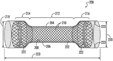
Fig. 2A depicts an exemplary stent having a micro-textured surface region, while fig. 2B depicts the stent of fig. 2A further including a delivery sheath.
Fig. 3 is an alternative embodiment of a stent having a micro-textured surface region.
Fig. 4 is a schematic view of an embodiment in which the textured area is provided as a ribbon.
FIG. 5 depicts a stent having a hydrogel coating disposed on the cuffed or flared ends of the stent.
Fig. 6 depicts a two-part stent including a stent and a retaining sleeve.
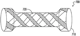
Fig. 7 depicts a stent having fixation regions woven into the stent.
Fig. 8 depicts a stent having a fixation region disposed on a flared region and also having a smooth region on the stent body. In this embodiment, the spring constant of the stent body may be selected to match the spring constant of the esophagus into which it is inserted.
Fig. 9 depicts a stent having a plurality of surface texture regions arranged annularly around the stent body with a selected spatial periodicity alternating with sliding regions.
FIG. 10 depicts an embodiment of a stent in which the first end includes a cuffed or flared region having surface texture and the second end is free floating within a body lumen. The free end may include axially oriented smooth ribs.
Fig. 11 depicts an esophageal stent including a surface textured region. The stent body advantageously expands in response to peristaltic waves from the body lumen.
Fig. 12 depicts a stent that includes a flared or flared region that is displaced relative to a centerline of the stent body.
Fig. 13 depicts a stent comprising sliding ribs and surface textured areas. In this embodiment, the surface textured region is capable of engaging esophageal growths in the esophagus.
Detailed Description
The following description is illustrative of the principles of the present disclosure and is not intended to limit the disclosure to the particular embodiments shown herein.
The stent performs three functions: 1) stents or holding open body lumens, 2) preventing ingrowth into the body lumen, and 3) anchoring or securing functions 1 and 2 at specific sites within the body lumen.
Generally, it is not clinically required that the stent portion responsible for the anti-migration or fixation feature should be permanently fixed to the stent portion responsible for the radial force component. In other words, the anti-migration function and the scaffold function may be completely separated in structure. In the present disclosure, a stent is considered to be all components of a lumen opening device implanted in a body.
Thus, embodiments can be divided into three categories: 1) a fixation region integral with the stent, 2) a fixation region separable from the stent, and 3) a fixation region both separable and integral with the stent. In the third category, the fixation region provides the dual function of providing fixation and preventing ingrowth.
Textured surface fixation
The textured surface responsible for the fixation or gripping features of the stents of the present invention includes texture that initially produces a cassie state and a wenzel state when exposed to the fluid environment within the mammalian body. These states evolve in situ, their evolving analogs differ from the typical wenzel and cassie states in that they involve a solid hydrophilic phase, a liquid hydrophobic phase and a liquid hydrophilic phase or a solid hydrophobic phase, a liquid hydrophilic phase and a liquid hydrophobic phase. In these modified Wenzel and Cassie states, the trapped phase, which is similar to the classical gas phase, is a liquid hydrophobic phase. Alternatively, the trapped gas phase is preferentially replaced by the liquid hydrophobic phase.
When the three phases are in contact with each other, the cassie and Wenzel phenomena occur. In vivo, the corresponding states result in the formation and retention of a liquid hydrophobic membrane implant in the Cassier state, and the retention of tissue (containing lipids) in the Wenzel state. In a hybrid Cassie-Wenzel state, where one texture scale (texture scale) is Wenzel and the other is Cassie, the implant can be positioned to the tissue surface.
The scale of interaction is defined by the surface texture of the current stent surface and is typically graded and characterized by at least two spatial scales, one on the order of micrometers (μm) and the other on the order of 10 to 100 μm. The surface texture may induce one state with a large difference between advancing and receding contact angles (contact angle hysteresis) or another state with a small contact angle hysteresis. The states of interest are referred to as the Wenzel state and the Cassie state, respectively. Each of the hierarchical spatial scales may induce a Wenzel or Cassie state, respectively, such that combinations are possible over multiple spatial scales. It is this combination of states that results in the surprising non-traumatic grasping characteristics of the present stent.
Examples of geometric structures having an interaction dimension include a cylinder, a cube, a pyramid, or any feature having typical overall dimensions. For example, in the case of a cube, the interaction dimension would be the length of the cube. These surface structures, characterized by an interaction dimension, are typically spaced apart by a center-to-center distance at a spatial frequency known as pitch. For example, 4 μm squares with a pitch of 8 μm means that the squares are separated by 4 μm on their surface. Typically, the spacing is 1 to 10 times the interaction dimension. Also typically, with regard to the hierarchical arrangement of different interaction scales, the different interaction scales and spacings are 1 to 10 times smaller than the next hierarchical level. In many cases, one size interaction is located over one large size interaction. For example, 1 μm pillars are placed on the top surfaces of 10 μm pillars with a pitch of 1 μm and 10 μm, respectively.
These textures create a phenomenon between the hydrophobic and hydrophilic components of the mixture that are placed at the surface interface. For example, the smaller interaction dimension is hydrophobic, while the larger interaction dimension is hydrophilic. The hydrophobic surface attracts the hydrophobic components in the interfacial mixture and repels the hydrophilic components, the opposite.
The cassie-baxter model describes the interaction of a solid textured surface with water in a gaseous environment. In this model, air is trapped in the micro-grooves of the textured surface and water droplets settle on the composite surface comprising the air and the tops of the micro-protrusions. The importance of fractal dimension between textures at multiple scales has been well recognized, and many approaches have been based on fractal contribution, i.e., the dimensional relationship between different texture scales. However, regardless of the material used (organic or inorganic) and the geometry of the surface texture (particles, rod arrays or pores), multiple scales of texture in combination with low surface energy are required to obtain a so-called superhydrophobic surface.
Superhydrophobicity is variously reported as a material that exhibits a contact angle with water that is greater than that achievable for a smooth, but strongly hydrophobic material. It is generally accepted that the minimum contact angle for a superhydrophobic substance is 150 degrees, and therefore most embodiments of the invention are not strictly superhydrophobic in this context, although this option is not excluded. The reason for this is that the Wenzel-Cassie state is its hydrophobicity between the non-textured surface and the surface that creates the Cassie-Baxter interface. Superhydrophobicity is only one aspect of many interesting texture control mechanisms in optimizing the fixation of the scaffold of the invention, in which context the contact angle is less important than the contact angle hysteresis.
Hydrophobic surfaces repel water. The hydrophobicity of a surface can be measured, for example, by determining the contact angle of a drop of water on the surface. The contact angle can be measured statically or dynamically. Dynamic contact angle measurement may include determining an advancing contact angle or a receding contact angle with respect to an adherent substance, such as a water droplet. Hydrophobic surfaces with a small difference between advancing and receding contact angles (i.e., low contact angle hysteresis) result in surfaces with low resistance to in-plane translation (low adhesion). Water can travel more easily across a surface with low contact angle hysteresis than across a surface with high contact angle hysteresis, and thus the magnitude of the contact angle hysteresis can be equated to the amount of energy required to move a substance.
High surface area is achieved by stacking multiple structures one on top of the other. When these multiple structures differ sufficiently in dimension, the superposition of these structures is referred to as a hierarchical structure or pattern. A subset of surfaces useful in the present invention are characterized as superhydrophobic.
Surface textures that can be used in the stents disclosed herein provide gripping or fixation areas when in contact with a body lumen, such as an esophageal lumen. The surface texture may comprise at least one type of hydrophobic region in at least one spatial interaction dimension and at least one type of hydrophilic region in one or more other spatial interaction dimensions, wherein the ratio of any two spatial dimensions is greater than 2.
One example of a surface texture that can be used in the present stent is a biological simulation of a natural rose pattern. Referring to fig. 1, pattern 100 includes three structures: 1) a two-dimensional sinusoidal pattern 102, 2) a first column pattern 104, and 3) a second column pattern 106, which is combined with a groove pattern 108 disposed on the second column 106. These structures have characteristic dimensions. For example, the amplitude 110 and pitch 112 of the sinusoidal pattern 102 are in the range of 50 to 500 μm or more. The height 114, diameter 116 and pitch 118 of the first pillar pattern are in the range of 20-50 μm. The height 120, diameter 122 and pitch 124 of the second pillar pattern and the height 126 and pitch 128 of the trenches 108 are in the range of 20-50 μm.
Fastening integral with the support
According to one embodiment of the invention, the bracket may be manufactured by using an injection molding process. By utilizing this process, the specific surface texture of the stent can be controlled by cutting the reverse surface texture pattern into the inner diameter of the mold. As shown in fig. 1, the inner surface of the mold may contain any of a variety of geometric patterns, such as sinusoids, cylinders, pyramids, or grooves, arranged in stages and having different spatial dimensions.
In some embodiments, a low profile geometry on the outer wall of the stent will minimize migration while preventing tissue damage in situ or upon removal. In addition, due to their hierarchical arrangement, these structures allow fluid to flow between the stent and the body lumen. For example, if the stent passes through the pancreatic or cystic duct, fluid from the pancreatic or cystic duct may pass between the wall of the bile duct and the outer surface of the stent.
In one embodiment, the present invention comprises a stent, and more preferably, a stent adapted for placement within the Gastrointestinal (GI) tract of an animal or human. In another embodiment, the GI tract comprises the esophagus, pancreatic duct, cystic duct, or common bile duct. In yet another embodiment, the outer surface of the implant includes at least one surface texture that provides a fixation area to help limit potential migration of the implant within the body lumen. In addition to its use as an esophageal prosthesis, the present invention can be used in any body vessel bundle (vessel), for example, in the coronary or peripheral vascular system, esophagus, trachea, bronchi, colon, biliary tract, urinary tract, prostate, brain, and in various other applications in the body.
Fig. 2A depicts a stent 200 of the present invention. In one embodiment, the stent 200 includes a stent body 202 having an axial length 224. When the stent 200 is not subjected to any external load or stress, the stent 200 assumes a normal or relaxed configuration, as depicted in fig. 2. The stent body 200 may be partially or fully covered with an elastomeric film or membrane 204. The elastomeric membrane 204 is defined by an outer surface 206 and an inner surface 208. The membrane may be disposed axially along the stent to cover substantially the entire axial length of the stent. The stent 200 comprises an open, woven configuration of mesh segments 210. Mesh segment 210 may be a wire or polymer mesh and, in some embodiments, provides a flexible scaffold structure. The wires or sections 210 may be paired and helically wound.
The stent 200 includes several regions, including a middle region 212, a distal cuff region 214, and a proximal cuff region 216. The distal cuff region 214 and the proximal cuff region 216 may be shaped to have a wider cross-section than the middle region 212, e.g., the middle region 212 may be used as an esophageal prosthetic device. The distal cuff region 214 and the proximal cuff region 216 may include flared or dilated regions having cross-sections 218 and 220. The diameter of the cuff region and/or flare is greater than the diameter of the intermediate region and aids in the securement of the stent when inserted into a body lumen.
The stent 200 also includes a surface texture disposed on a portion thereof that provides a fixation area for the stent. As depicted in fig. 2A, in some embodiments, surface texture 222 may be provided on flare regions 218 and 220. The surface texture 222 may be the three-dimensional geometry depicted in fig. 1, and may be integrally formed with the elastomeric film 204. The surface texture 222 provides the prosthesis 200 with an anti-migration effect.
This embodiment provides improved stent fixation and is particularly effective in preventing proximal or distal migration of stent 200 when stent 200 is inserted into a body lumen. The flare cuffs 218, 220 may be designed to be flexible to readily accommodate changes in the body lumen wall during fluid or food delivery. Alternatively, the present invention also contemplates a stent body that has no flared end, or includes a flared end.
In some embodiments, each end of the stent includes a fixation region. In some embodiments, the fixation region comprises an inflatable ring. In other embodiments, the textured region comprises an elastic polymeric annulus.
Fig. 2B depicts an embodiment of the stent 200, the stent 200 having a delivery sleeve 223 disposed around the exterior of the stent body 200. The delivery sleeve may be disposed around any region of the stent 200, including at least one of the middle region 212, the distal cuff region 214, and the proximal cuff region 216. The delivery sheath advantageously facilitates positioning and deployment of the stent within the body lumen.
Generally, the outer surface 206 of the stent 200 may be designed to be fairly smooth. A surface texture 222, such as the three-dimensional geometry depicted in fig. 1, may be integrally formed with the elastomeric film 204. The surface texture 222 provides the prosthesis 200 with an anti-migration effect.
As depicted in fig. 1, surface texture 222 may be a three-dimensional geometry that includes relief features, such as pillars, sinusoids, or grooves. However, surface texture 222 may include protrusions or depressions of any shape or other complex geometry, including graded and alternating regions of differing hydrophilicity on outer surface 206. When formed with surface texture 222 disposed on outer surface 206, stent body 200 is imparted a wet surface gripping function on all or a portion of surface 206 that serves as a fixation area between stent body 200 and the body lumen in which stent body 200 is disposed.
The surface texture 222 can be configured to accommodate various tolerances in the delivery system that will be used with the stent body 200 in some embodiments. For example, the stent body 200 is depicted in fig. 2 in its relaxed or normal configuration. As depicted, the middle region 212 may have a diameter of about 15-20mm, and the cuff of the proximal region 214 and/or the cuff of the distal region 216 may have a diameter of about 25-28 mm. In this particular embodiment, the wire 210 may have a diameter of about 0.22mm or less. The three-dimensional structure 222 may preferably have a cross-section of less than about 1 mm. This tolerance ensures that the overall diameter increase of the delivery device is kept, for example, to less than 2mm (assuming a three-dimensional structure 222 is wrapped around the stent). However, the invention is not limited by the exemplary dimensional tolerances. The overall diameter may vary depending on the use of a particular delivery device in a particular tube bundle. For example, the dimensional tolerances of an esophageal stent may be different from a coronary stent.
Fig. 3 depicts yet another embodiment of the invention in which the surface texture layer 322 is not integrally formed with the elastomeric film 304. As depicted in fig. 3, a thin discrete layer may be disposed on the outer surface 306. In a particular embodiment, the anti-migration structural layer 322 forms a pattern that expands helically around the outer surface 304 of the endoluminal prosthesis 300. According to one embodiment of the invention, the surface texture 322 may be formed from the same material as the elastomeric film 304. In some embodiments, the surface texture 322 may be in the form of bands spanning a common longitudinal axis of the stent body 300.
In another embodiment, the stent body 300 may be provided with a first set of anti-migration bands comprising surface textures 322, the surface textures 322 having a common winding direction but being circumferentially displaced with respect to each other. In this embodiment, the first set of anti-migration bands comprising the surface texture 322 may be configured to pass through a second set of anti-migration bands that are also circumferentially displaced relative to each other, but wound in substantially opposite directions. In this embodiment, the stent body 300 is sufficiently configured to have anti-migration properties, as provided by an anti-migration band. The direction of the inventive belt is not limited by the above examples and may also extend longitudinally or perpendicular to the longitudinal axis. Further, the bands may change direction at random locations, e.g., they may bend or undulate at random locations along the stent 300.
The device 300 of the present invention may include a surface texture 322, the surface texture 322 being provided as a band configured to flex along certain selective dimensions. For example, the surface texture bands 322 may include an anti-migration structure that is flexible in a radially outward direction of the stent body 300. Further, the surface texture 322 may be rigid in the longitudinal direction at certain locations.
Various methods of forming a stent are provided herein. In one embodiment, the surface texture 222 may be added to the wire 210 after the outer surface 206 is disposed on the wire 210 during the manufacturing process of the stent body 200. In alternative embodiments, the surface texture 222 may be provided as a layer integrally formed with the filament 210. Instead of a layer completely wrapped on the outer surface 206, bands of surface texture 222 may be interwoven with the filaments 210. In this embodiment, the surface texture 222 may partially or completely replace the elastic film 204.
Fig. 4 depicts a portion of a stent body 200. The surface texture 422 may be provided as an anti-migration band 430 having a width 432 less than a distance 434 between the filaments 410. In an alternative embodiment, the bands 436 may have a width 440 along the exposed portions 438 that is greater than the distance 434 between the filaments 410. Further, the stent 400 may be configured with multiple bands 422 of different widths.
Another advantage provided by the surface texture as the anti-migration strips 430 disposed on the elastomeric film is that it can provide structural reinforcement along the stent body. Such reinforcement may enable the filament 410 to be configured at a reduced angle. As used herein, the angle between the wires 410 is measured based on their tilt deviation from the axis 440 of the stent.
In prior stents, an angle 436 of 45 degrees from the axis 440 may be considered a practical lower limit for the angle of the mesh or open weave wire stent 200. However, the braid angle with the axis 440 can be reduced to as low as 20 degrees with the present invention. The advantage of the lower angle of the wire 410 is that the angle may contribute to the structure of the stent in the ratio of axial foreshortening to radial increase thereof. The lower angle facilitates greater radial expansion of the stent body 200 as the stent is expanded either through the use of self-expanding materials or with the aid of a balloon. With a reduced braid angle, upon expansion, there may be less axial shortening for a given radial expansion. Due to the reduced axial foreshortening, the stent body 200 may be more accurately positioned within the body lumen during its deployment. Thus, the contours of the surface texture 422 in combination with the stent 200 resist extraneous stretching and aid in the precise positioning of the stent within the body lumen.
There are a variety of clinically preferred arrangements of the anti-migration layer depending on the application. The possible scenarios are: full coverage of the stent, a spiral pattern formed using ribbons, a square or circular checkerboard pattern at the intersection of the filaments, and predominantly in the end regions (flared) and segmented or continuous bands.
Generally, the device is covered with an elastomeric membrane to enhance the patency of the lumen. In addition, the tubular coating may prevent tumor ingrowth. The thickness of the elastomeric film may be in the range of 0.075-0.25 mm. However, such elastomeric films may also range up to 0.75-1.00 mm. In some embodiments, the elastomeric film may include a silicone film layer. The elastomeric film 204 can be disposed on the outer surface of the stent body 200 by any desired means, including by placing the elastomeric film on a surface, by extruding the elastomeric film onto the outer surface, or by dipping or spraying the elastomeric film onto the outer surface.
The elastomeric membrane of the prosthesis may also be formed of polytetrafluoroethylene (PTFE/ePTFE). Considered alone, the coating should provide an effective barrier to tissue ingrowth. Furthermore, the elastomeric film may be elastic and thus may expand radially like the rest of the stent body. Thus, the silicone construction can generally be engineered to apply a constant, gentle pressure to help accommodate normal lumen patency, such as esophageal peristalsis, as its smooth inner surface helps to promote the passage of fluids. Optionally, the ends of the prosthesis may also be reinforced with a continuous polymer film to help resist hyperplasia.
All components of the intraluminal device should be made of biocompatible materials, including metallic or polymeric materials. Any material may be used to form these elements. In one embodiment, the elastomeric film preferably comprises silicone, although other materials having elastomeric and biocompatible properties are also contemplated by the present invention. By way of example and not by way of limitation, other materials for any or all of the components of the device may include polyurethane, polyethylene, polytetrafluoroethylene or expanded polytetrafluoroethylene, polyolefins such as high density polyethylene and polypropylene, polyolefin copolymers and terpolymers, polyethylene terephthalate, polyesters, polyamides, polyurethaneureas and polycarbonates, polyvinyl acetate, thermoplastic elastomers (including polyether-polyester block copolymers, polyvinyl chloride, polystyrene, polyacrylates), polymethacrylates, polyacrylonitrile, polyacrylamides, silicones, combinations and copolymers thereof, and the like.
Other useful coating materials include any suitable biocompatible coating. Non-limiting examples of suitable coatings include hydrophilic materials, hydrogels, and the like. Useful hydrophilic coating materials include, but are not limited to, alkylene glycols, alkoxy polyalkylene glycols such as methoxy polyethylene oxide, polyoxyalkylene glycols such as polyethylene oxide and copolymers thereof, polyethylene oxide/polypropylene oxide copolymers, polyoxyalkylene modified polydimethylsiloxanes, polyphosphazenes, poly (2-ethyl-2-oxazoline), (meth) acrylic acid, homopolymers and copolymers of poly (acrylic acid), maleic anhydride copolymers (including copolymers of methyl vinyl ether and maleic acid), pyrrolidones (including poly (vinyl pyrrolidone) and derivatives thereof), vinyl pyrrolidone, homopolymers and copolymers of poly (vinyl sulfonic acid), acrylamides (including poly (n-alkylacrylamide), poly (vinyl alcohol), poly (ethyleneimine), poly (carboxylic acid)), methylcellulose, poly (ethylene glycol), poly (propylene glycol), poly (ethylene glycol), poly (propylene glycol), poly (ethylene glycol), poly (propylene glycol, poly (ethylene glycol), poly (ethylene glycol), poly (propylene glycol, poly (ethylene glycol), poly (propylene glycol), poly (ethylene glycol), poly (propylene glycol), poly (ethylene glycol), poly (propylene glycol), poly (ethylene glycol, poly (propylene glycol, poly (ethylene glycol), poly (propylene glycol), poly (ethylene glycol, poly (propylene glycol), poly (ethylene glycol), poly (ethylene glycol, poly (propylene glycol), poly (ethylene glycol), poly (propylene glycol), poly (ethylene glycol), poly (propylene glycol), poly (ethylene glycol), poly (propylene glycol, poly (ethylene glycol), poly (ethylene glycol, Carboxymethyl cellulose, hydroxypropyl cellulose, polyvinyl sulfonic acid, water-soluble nylon, heparin, dextran, modified dextran, hydroxylated chitin, chondroitin sulfate, lecithin, hyaluronic acid, and combinations and copolymers thereof, and the like.
Other non-limiting examples of suitable hydrogels include hydroxyethyl acrylate or (meth) hydroxyethyl acrylate; polyethylene maleic anhydride, combinations and copolymers thereof, and the like.
Other useful synthetic biocompatible polymeric materials include, but are not limited to, polyesters, including polymethyl acetate, naphthalate derivatives, and silk. The polymeric material may further comprise a metal, glass, ceramic or carbon component or fiber. Useful and non-limiting examples of bioabsorbable or biodegradable polymeric materials include poly (L-lactide), poly (D, L-lactide), poly (glycolide), poly (L-lactide-co-D, L-lactide), poly (L-lactide-co-glycolide), poly (D, L-lactide-co-glycolide) (PLA/PGA), poly (glycolide-co-trimethylene carbonate) (PGA/PTMC), polydioxanone, polycaprolactone, polyhydroxybutyrate, poly (phosphazene), poly (D, L-lactide-co-caprolactone), poly (glycolide-co-caprolactone), poly (phosphate ester), and the like. Some other materials that may be used as filaments include, but are not limited to, polyetheretherketone, fluorinated ethylene propylene and polyimide, polybutylene terephthalate, polyurethane rubber, and silicone rubber.
Any component of the prosthetic device, particularly the anti-migration structural layer, may also include a therapeutic agent that may be released into the body. Useful therapeutic agents or drugs include, but are not limited to, antiplatelet drugs, antithrombin drugs, antineoplastic drugs, antiproliferative agents, anti-plaque forming agents, cytostatic agents, and antiproliferative agents, or other drugs for a particular purpose. This may also include gene therapy agents. The therapeutic agent or drug is preferably selected from the group of therapeutic agents or drugs consisting of: urokinase, D-phenylalanine proline arginine chloromethyl ketone, enoxaparin, angiopeptin, acetylsalicylic acid, paclitaxel, 5-fluorouracil, cisplatin, vinblastine, vincristine, sulfasalazine, mesalamine, heparin sodium, low molecular weight heparin, hirudin, prostacyclin and prostacyclin analogs, dextran, glycoprotein Ilb/IIIa platelet membrane receptor antibodies, recombinant hirudin, thrombin inhibitors, calcium channel blockers, colchicine, fibroblast growth factor antagonists, fish oil, omega 3-fatty acids, histamine antagonists, HMG-CoA reductase inhibitors, methotrexate, monoclonal antibodies, sodium nitroprusside, phosphodiesterase inhibitors, prostaglandin inhibitors, suramin, serotonin blockers, steroids, thiol protease inhibitors, triazolopyrimidines, and other antagonists of PDGF, Interferon-alpha and genetically engineered epithelial cells and combinations thereof. The foregoing list of therapeutic agents is provided as an example and is not meant to be limiting as other therapeutic agents and drugs may be developed that are equally suitable for use with the present invention.
The stent of the present disclosure may be manufactured from a mold comprising a top portion and a bottom portion. The top portion may comprise an inner surface and an outer surface, wherein the inner surface may be adapted to receive a material for manufacturing a stent according to the present invention. The holder may be formed as a hollow structure, which may be etched, or may be formed as a spiral structure like a coil spring. U.S. patent application serial No. 10/683,314 filed 10/2003 discloses suitable materials and geometries for the stent.
In another alternative method of manufacture, the stent may be formed by modified molding of the outer surface onto a separate layer of material, such as a nonwoven material. As used herein, the term "nonwoven" and variations thereof refer to materials formed by casting, molding, spinning, or extrusion techniques, excluding typical textile forming techniques such as knitting, weaving, knitting, and the like. Non-limiting examples of useful polymeric materials for the non-woven polymer graft portion include polyester, polypropylene, polyethylene, polyurethane, polynaphthalene, polytetrafluoroethylene, expanded polytetrafluoroethylene, silicone, and combinations and copolymers thereof. Desirably, the polymeric material is polytetrafluoroethylene, including expanded polytetrafluoroethylene.
The stent may be formed from a variety of configurations and from a variety of materials known to those skilled in the art. In particular, conventional esophageal stents can be used or readily modified for use in the present invention. Such stents may be non-expandable or expandable, including those commonly used to address the problem of progressive dysphagia associated with esophageal cancer. Expanded stents include those stents that are deformable and typically expanded using, for example, a balloon catheter, as well as those stents that are resilient in nature and can be delivered in a compressed state and can self-expand to their original state. Preferably, the stent is radially self-expanding to facilitate deployment in the esophagus. Typically, such stents are made of stainless steel or nitinol (nickel titanium alloy) and are formed into configurations such as knitted wire tubes, tubular meshes, helical springs, and the like. Suitable self-expanding esophageal metal stents include those sold under the tradenames EdopachoilTM (Medtronic/Insent, Eden Prairie, Minn.), Ultraflex (Boston Scientific/Microvasive, Natick, Mass.), WallstentTM (Boston Scientific/Microvasive, Natick, Mass.), and Z-tentTM (Wilson-Cook, Winston-Salem, N.C.). Additional examples of such stents include those described in U.S. patent nos. 5,876,448 and 6,248,058, each of which is incorporated herein by reference in its entirety. For most applications, the length and diameter of the stent may typically be in the range of 6-15cm (length) and 16-22mm (diameter). The stent may also be partially or fully coated with a polymer film such as silicone, for example.
Any stent may have a covering and thus the covering is not limited to a nitinol stent. Furthermore, the stent need not be covered, and may be partially covered or fully covered. The stent may also have a covering on the inside, the outside, or both.
Other suitable cover materials may also be used. Examples of other suitable cover materials include, but are not limited to, polyethylene, polypropylene, polyvinyl chloride, polytetrafluoroethylene (including expanded polytetrafluoroethylene), fluorinated ethylene propylene, polyvinyl acetate, polystyrene, poly (ethylene terephthalate), naphthalene, dicarboxylic acid derivatives (e.g., polyethylene naphthalate, polybutylene naphthalate, polypropylene naphthalate, and trimethylenenaphthalate), polyurethane, polyurea, polyamide, polyimide, polycarbonate, polyaldehyde, polyetheretherketone, natural rubber, polyester copolymers, styrene-butadiene copolymers, polyethers (e.g., fully or partially halogenated polyethers), and copolymers and combinations thereof.
Alternatively, the stent may have a braided construction with a flared proximal end. In this embodiment, the stent is an esophageal stent. The stent may be formed from any suitable stent material, including metallic and non-metallic materials and shape memory materials. Examples of suitable materials include, but are not limited to, shape memory alloys such as nitinol, other metallic materials such as stainless steel, tantalum, titanium, nickel chromium or cobalt chromium alloys, such as those sold under the Elgiloy brand. The stent may have a flared distal end or flared proximal and distal ends.
Hydrogel pad support
In fig. 5, the hydrogel coated stent 500 is shown in its expanded form. Hydrogel coated stent 510 includes a proximal cuff or flare 525, an elongated body 520, a distal cuff or flare 530. A hydrophilic polyurethane hydrogel 535 is disposed around at least one of the proximal cuff 525 and the distal cuff 530 of the stent 510. Preferably, the proximal cuff 525 comprises a hydrophilic polyurethane hydrogel. In accordance with another aspect of the present disclosure, both cuffs 525 and 530 include a polyurethane hydrogel.
Each of the cuffs 525, 530 is similar in diameter to the elongate body 520 when initially inserted into a body tube bundle and allows continuous fluid flow around the exterior of the stent 510. However, upon exposure to an aqueous environment (i.e., bodily fluids), the polyurethane hydrogel swells, thereby increasing the outer diameter of the cuffs 525, 530. This increase in diameter causes the cuffs 525, 530 to apply a sealing force against the wall of the body tube bundle. This sealing force resists the flow of bodily fluids between the cuffs 525, 530 and the walls of the tube bundle, forcing all fluid flow in and out through the stent 510.
The use of hydrophilic polyurethane hydrogels can potentially reduce the incidence of encrustation and the incidence of concurrent infection. However, if the polymer layer is a polyurethane hydrogel, the polymer layer will expand or swell when exposed to an aqueous environment, allowing the struts of the stent graft to bend more freely without kinking.
The polyurethane hydrogel layer represents a three-dimensional network of crosslinked hydrophilic macromolecules that can swell and absorb about 20-90% by weight of water. The hydrogel layer may be applied as or onto the cuff of the stent graft by coating, adhesive bonding, lamination, extrusion or moulding. The application method used is selected to provide a hydrogel layer having a substantially uniform thickness.
Stents may include expandable or inflatable structures embedded in a polymer matrix or a solid polymer matrix. In both cases, the polyurethane hydrogel may be applied as a band or band disposed around the outer surface of the cuff, such as a torus shape or ring.
After the hydrogel is placed around the cuff of the stent, it may be dried by any method known in the art, including but not limited to conduction drying, convection drying, hot air impingement, steam treatment, infrared irradiation, ultraviolet irradiation, and microwave irradiation. Preferably, the hydrogel coating is dried by application of thermal energy.
Drying the hydrogel causes it to shrink in size. The hydrogel cuff dried stent may be contracted to a cross-section ready for insertion into a body vessel bundle. In this case, the hydrogel cuff may have substantially the same diameter as the elongate body 520 of the stent 510. In some cases, the act of drying the polyurethane gel will result in the stent being in a collapsed state. If the hydrogel forms around the mesh, the gel will only expand in a direction perpendicular to the mesh. The shape and the ratio of polyurethane to water are predetermined at the time of polymerization.
The anti-migration surface texture may be applied to the hydrogel or elsewhere on the scaffold. If applied to a hydrogel, the surface texture may be applied in the dry state or in the wet state of the hydrogel. In either case, the surface texture may be applied as an elastomeric layer or segmented layer, or formed in the hydrogel itself.
Fastening separate from the support
In some cases, once the stent is deployed, the position of the stent may move relative to its position in the body lumen prior to deployment. After deployment of the stent, it may be difficult to reposition the stent. In some cases, repositioning of the stent may be facilitated by separating the stent function from the fixation function.
Referring to fig. 6, a two-part stent 610 includes a conventional wire stent 612 and a retaining sleeve 614. The stent 610 is shown in its expanded state. To deliver the stent, the stent 610 collapses. Once deployed, the outer cannula surface 616 with the surface texture 618 engages the inner wall of the body lumen. Upon initial deployment, the wire holder 612 can be easily repositioned within the sleeve 614 without moving the sleeve 614 relative to the body lumen.
Preferably, the fixed area 624 is coated with a surface texture 622 of a water-soluble material such that the initial surface texture 622 is smooth. Optionally, a second coating surface texture may be placed on the inner surface 626 of the sleeve 614. The coating may be any material used in the pharmaceutical industry to delay the release of a drug.
After a predetermined time, the coating dissolves by rinsing or due to body fluids present in the body lumen. As the coating dissolves, the wire stent 612 is secured to the sleeve 614 and the sleeve 614 is secured to the inner wall of the body lumen, thereby securing the stent 610 within the body lumen.
Fastening separate from and integral with the support
In yet another embodiment, the fixation regions may be woven into the stent in a relatively loose configuration, which allows for repositioning of the stent without repositioning the fixation regions. After deployment, the loose configuration may be secured or fixed.
In one particular embodiment shown in fig. 7, stent 700 includes stent body 710 and moveable anchor element 720 is in the form of a patterned silicone strip. Stent 710 may be coiled or patterned as a braided or woven open network of filaments, fibers or filaments interwoven in a braided pattern to form tubular stent 700.
In this embodiment, moveable anchoring elements 720 may extend in the direction of the longitudinal axis of the stent and may be interwoven in the braided configuration of stent 710. Anchor element 720 may be fixed at one end, both ends, or at some point between the distal and proximal portions of the stent. The anchoring element may include a surface texture as described herein.
Any number of strips may be used. Suitably, at least two strips are symmetrically positioned around the circumference of stent 700 to provide uniform anchoring in the body lumen.
Furthermore, a single circumferential ring of anchoring elements may be positioned in the middle of the stent to prevent the stent from "walking", which may occur if the anchoring elements are positioned at both ends of the stent.
Referring to fig. 8, the esophageal stent 800 includes a stent body 802 and an expanded region 804, and a surface texture 806 is provided on the expanded region 804 to provide a fixation region. A smooth region 808 is provided in the middle of the stent body 802. The spring constant of the stent body 802 may be designed to match the spring constant of the target esophagus.
Referring to fig. 9, the esophageal stent 900 includes a stent body 902 and an expanded region 904, wherein a surface texture 906 is provided as an annular band and is disposed on the stent body 902 with a certain spatial periodicity. In this embodiment, the wavelength of the peristaltic motion of the target esophagus is known. For example, for the adult esophagus, the peristaltic wavelength is about 5 cm. When stent 900 is placed in a human esophagus, surface texture 906 is placed with a Z wavelength interval 908 such that esophageal peristaltic waves 910 slide alternately in region 912 and grip the esophageal wall in region 914. This arrangement of the gripping surface allows esophageal peristaltic waves to pass without displacing the esophageal stent 900 relative to the esophagus 916. Alternatively, the spacing 908 may be one wavelength. Alternatively, the surface texture 918 may be provided on the cuff or flared region 904.
The sliding region of fig. 8 and 9 may include a lubricating film, such as silicone or a gel, such as a hydrogel.
Referring to fig. 10, the esophageal stent 1000 includes a stent body 1002 and a flare or cuff area 1004 with surface textures 1006 disposed on the stent body 1002. In this embodiment, one end 1008 is free floating within the esophagus. Optionally, the end 1008 may be configured with axially oriented smooth ribs 1010 so that the esophagus is induced to slide axially without displacement of the stent end 1008. The ribs 1010 may be of sufficient height to prevent rotational displacement of the bracket end 1008. Alternatively, the hydrogel may be disposed on the ribs 1010.
Referring to fig. 11, an esophageal stent 1100 includes a stent body 1102 and a cuff or flared region 1104, with surface textures 1106 provided on the stent body 1102. When the stent body 1102 is compressed by the peristaltic wave 1110 in direction 1108, the stent body 1102 expands in direction 1112 such that the stent body 1102 remains in contact with and follows the peristaltic wave 1110. Optionally, the stent body 1102 may be provided with gripping regions 1106, the gripping regions 1106 having a peristaltic wave periodicity, as shown in fig. 9.
Referring to fig. 12, the esophageal stent 1200 includes a stent body 1202 and a flared region 1204, wherein a surface texture 1206 is provided on the stent body 1202. The cuff or flared region 1204 is displaced relative to the stent body centerline 1208. The displacements of the two cuffs or flared regions 1204 are ideally 180 degrees out of phase so that one end is displaced "up" and the other end is displaced "down". This configuration causes the middle of the stent body 1202 to deflect in the direction 1212 relative to the peristaltic waves 1210. Thus, the stent body 1202 follows the peristaltic wave 1210.
Referring to fig. 13, esophageal stent 1300 includes a stent body 1302 and a cuff or flared region 1304, wherein sliding ribs 1306 are provided on stent body 1302. The primary fixation region 308 is designed to engage an esophageal growth 1310 on the esophagus 1312. Alternatively, the region 1308 may be radially reinforced or stiffer than the expansion region 1304. Optionally, one cuff or flared region 1304 may be grasped, rather than slid.
Alternatively, some of the filaments used to weave the strips may be separate from the stent construction, such that when they are removed, the weave pattern is unraveled and the textured strips are released from the stent.
The description provided herein is not limited in scope by the specific embodiments described, which are intended as single illustrations of individual aspects of certain embodiments. The methods, compositions, and devices described herein may include any of the features described herein, alone or in combination with any other feature described herein. Indeed, various modifications will become apparent to those skilled in the art from the foregoing description and accompanying drawings, using no more than routine experimentation, in addition to the modifications shown and described herein. Such modifications and equivalents are intended to fall within the scope of the appended claims.
All publications, patents and patent applications mentioned in this specification are herein incorporated in their entirety by reference into the specification, to the same extent as if each individual publication, patent or patent application was specifically and individually indicated to be incorporated herein by reference. Citation or discussion of a reference herein shall not be construed as an admission that such is prior art.
Thus, while there have been described particular embodiments of the present invention with improved fixation of the brackets which are new and useful, it is not intended that such references be construed as limitations upon the scope of this invention except as set forth in the following claims.
Claims (33)
1. A device for securing in a body lumen, comprising:
a tubular stent having an open, braided configuration with a stent body having an axial length, the stent body including first and second ends and an intermediate region, the stent having a predetermined normal configuration and being radially compressible to a reduced radius configuration; and
a continuous elastomeric film disposed axially along the stent, the continuous elastomeric film surrounding the stent about the axial length to define a barrier region of the stent to prevent tissue growth through the stent along the barrier region; and is
Wherein a portion of the barrier region of the stent comprises a surface texture for contacting the body lumen to provide a fixation region of the stent to positively fix the stent within the body lumen at a treatment site by radial expansion of the stent into engagement with a surface of a tissue wall segment defining the body lumen, and
wherein the surface texture comprises at least one type of hydrophobic areas and at least one type of hydrophilic areas, wherein the at least one type of hydrophobic areas and the at least one hydrophilic area are arranged in a hierarchy, and wherein the at least one type of hydrophobic areas comprises a first spatial dimension, the at least one type of hydrophilic areas comprises a second spatial dimension different from the first spatial dimension, and the ratio of the first spatial dimension and the second spatial dimension is larger than 2.
2. The apparatus of claim 1, wherein:
the stent is flexible so as to assume a reduced radius configuration in response to application of an external force and tends to assume the normal configuration in the absence of the external force.
3. The device of claim 2, wherein the elastomeric membrane reinforces the scaffold along the barrier region.
4. The device of claim 3, wherein the film comprises silicone.
5. The device of claim 3, wherein the fixation region of the stent exerts a lower restoring force in its return toward the normal configuration relative to a non-textured region of the stent upon removal of an external force.
6. The device of claim 5, wherein the fixation region comprises an inflatable ring at each end of the stent.
7. The device of claim 5, wherein the fixation region comprises an elastomeric polymer annulus at each end of the stent.
8. The device of claim 7, wherein the polymer annulus comprises a dry hydrogel.
9. The device of claim 1, wherein the surface texture is disposed on the first end and the second end.
10. The device of claim 9, wherein the surface texture is disposed on the first end and the second end in a segmented pattern.
11. The device of claim 1, wherein the barrier region has a diameter that is less than a diameter of the fixation region when the stent is in the deployed configuration.
12. The device of claim 1, wherein the elastomeric membrane reinforces the scaffold along the barrier region.
13. The device of claim 1, further comprising a removable and low durometer delivery sleeve disposed on an outer surface of the stent, the sleeve following the outer surface, wherein the sleeve separates the body lumen from the fixation region of the stent to allow positioning of the stent within the body lumen without engaging the fixation region with the body lumen.
14. The device of claim 1, wherein the surface texture comprises anchoring elements in the form of strips and the anchoring elements are located in the middle of the stent.
15. The apparatus of claim 1, wherein the stent further comprises a flared region comprising the surface texture, and a smooth region disposed on a middle region of the stent body.
16. The device of claim 1, wherein the stent body comprises a spring constant that is +/-25% of a spring constant of the body lumen into which the stent is inserted.
17. The device of claim 15, wherein the surface texture is disposed on the stent body in annular bands having a spatial periodicity of between 1/2 and 3 times the wavelength of peristaltic motion of the body lumen, and wherein the smooth regions are disposed between the annular bands.
18. The device of claim 1, wherein one end of the stent is smooth.
19. The device of claim 1, wherein when the stent body is axially compressed by a peristaltic wave, the stent body expands such that the stent body remains in contact with the body lumen and follows the peristaltic wave.
20. The device of claim 1, wherein the ends of the stent are flared and spatially separated by an axial length corresponding to a nerve wavelength of a peristaltic motion of a target esophagus.
21. The device of claim 1, wherein the bracket further comprises a sliding rib provided on the bracket body at either of the ends.
22. A device for securing in a body lumen, comprising:
a flexible tubular stent having a predetermined normal configuration and being radially compressible to a reduced radius configuration in response to an external compressive force; the stent radially expands to the normal configuration in the absence of the external compressive force, thereby securing the stent within the body lumen; and
an elastically deformable reinforcement sleeve integral with said stent and disposed axially along and substantially surrounding said stent to provide a reinforced region of said stent that requires at least one minute to return to said normal configuration after removal of said external compressive force;
wherein a portion of the stent is substantially free of the reinforcement sleeve and includes a surface texture that provides a fixation region of the stent, wherein the fixation region radially expands with a smaller restoring force than the reinforcement region upon removal of the external compressive force;
wherein the fixed area comprises a surface texture comprising at least one type of hydrophobic area and at least one type of hydrophilic area, wherein the at least one type of hydrophobic area and the at least one hydrophilic area are arranged hierarchically, and wherein the at least one type of hydrophobic area comprises a first spatial dimension, the at least one type of hydrophilic area comprises a second spatial dimension different from the first spatial dimension, and a ratio of the first spatial dimension to the second spatial dimension is larger than 2.
23. The apparatus of claim 22, wherein: the elastically deformable reinforcement sleeve comprises a polymer film.
24. The device of claim 23, wherein the polymer film is a silicone film.
25. The device of claim 22, wherein the fixed region is disposed on a proximal cuff and a distal cuff, and the reinforced region comprises an intermediate region of the stent between the proximal cuff and the distal cuff.
26. The device according to claim 25, wherein the proximal cuff and the distal cuff have a diameter greater than a diameter of the intermediate region when the stent is in the normal configuration.
27. A device for fixation in a body lumen, comprising:
a tubular elastic stent having an open, braided configuration, the tubular elastic stent having a predetermined expanded configuration and being radially compressible to a reduced radius configuration in response to application of an external force, the stent being expanded to the expanded configuration in the absence of the external force; and is
Wherein a portion of the stent has a larger radius than other portions; and is
Wherein a detachable and low durometer fixation sleeve is placed on an outer surface of the stent, the fixation sleeve follows the outer surface of the stent when the stent is placed in compression, and the fixation sleeve follows the outer surface of the stent when the stent is deployed within a body lumen, and
wherein the retaining sleeve comprises an outer surface having a surface texture disposed thereon, the surface texture comprising at least one type of hydrophobic region and at least one type of hydrophilic region, wherein the at least one type of hydrophobic region and the at least one hydrophilic region are arranged in stages, and wherein the at least one type of hydrophobic region comprises a first spatial dimension, the at least one type of hydrophilic region comprises a second spatial dimension different from the first spatial dimension, and the ratio of the first spatial dimension to the second spatial dimension is greater than 2, and
wherein the retaining sleeve includes an inner surface that contacts the bracket.
28. The device of claim 27, wherein the fixation sleeve and the stent are attached by at least one of sutures, staples, or adhesives.
29. The device of claim 28, wherein the adhesive comprises two portions, wherein a first portion is disposed on the inner surface of the fixation sleeve and a second portion is disposed on the exterior of the stent such that when the fixation sleeve and stent are in contact, the adhesive is activated and attaches the fixation sleeve to the stent for a predetermined time.
30. The device of claim 28, wherein the adhesive is injected between the fixation sleeve and the stent.
31. The device of claim 27, wherein the fixation sleeve is absorbable.
32. A stent for fixation within a body lumen, the stent being capable of applying a sealing or anchoring force against a wall of the body lumen, the stent comprising:
a radially expandable cylindrical body having a proximal cuff, an elongated body and a distal cuff, the elongated body having a longitudinal length greater than the proximal and distal cuffs, the elongated body and the cuffs having substantially similar diameters, and a cross-linked hydrogel layer disposed on at least one of the cuffs,
the hydrogel layer has been pre-dried and comprises an embedded matrix and a surface texture layer; wherein, upon exposure to an aqueous environment, the pre-dried hydrogel layer swells such that the outer diameter of the cuff is greater than the outer diameter of the elongate body to apply a sealing force against a wall of a body vessel bundle,
and at least one fixed area comprising a surface texture comprising at least one type of hydrophobic area and at least one type of hydrophilic area, wherein the at least one type of hydrophobic area and the at least one hydrophilic area are arranged hierarchically, and wherein the at least one type of hydrophobic area comprises a first spatial dimension, the at least one type of hydrophilic area comprises a second spatial dimension different from the first spatial dimension, and the ratio of the first spatial dimension and the second spatial dimension is larger than 2.
33. The stent according to claim 32 wherein the pre-dried state of the hydrogel fixes the cuff in a reduced radius state suitable for introduction into the body lumen.
Applications Claiming Priority (3)
| Application Number | Priority Date | Filing Date | Title |
|---|---|---|---|
| US201662441087P | 2016-12-30 | 2016-12-30 | |
| US62/441087 | 2016-12-30 | ||
| PCT/US2017/069150 WO2018126238A1 (en) | 2016-12-30 | 2017-12-30 | Stents with improved fixation |
Publications (2)
| Publication Number | Publication Date |
|---|---|
| CN110381886A CN110381886A (en) | 2019-10-25 |
| CN110381886B true CN110381886B (en) | 2022-08-12 |
Family
ID=61054505
Family Applications (1)
| Application Number | Title | Priority Date | Filing Date |
|---|---|---|---|
| CN201780087791.8A Active CN110381886B (en) | 2016-12-30 | 2017-12-30 | Stent with improved fixation |
Country Status (5)
| Country | Link |
|---|---|
| US (2) | US10758380B2 (en) |
| EP (1) | EP3562436A1 (en) |
| CN (1) | CN110381886B (en) |
| TW (1) | TWI781131B (en) |
| WO (1) | WO2018126238A1 (en) |
Families Citing this family (21)
| Publication number | Priority date | Publication date | Assignee | Title |
|---|---|---|---|---|
| CA2882364C (en) * | 2013-03-15 | 2017-01-03 | Boston Scientific Scimed, Inc. | Anti-migration micropatterned stent coating |
| US11285274B2 (en) | 2016-05-03 | 2022-03-29 | Pneuma Respiratory, Inc. | Methods for the systemic delivery of therapeutic agents to the pulmonary system using a droplet delivery device |
| US20180311057A1 (en) * | 2017-04-26 | 2018-11-01 | Boston Scientific Limited | Inflatable stent |
| CA3064005C (en) | 2017-05-19 | 2023-03-07 | Pneuma Respiratory, Inc. | Dry powder delivery device and methods of use |
| CA3077475A1 (en) | 2017-10-04 | 2019-04-11 | Pneuma Respiratory, Inc. | Electronic breath actuated in-line droplet delivery device and methods of use |
| CA3079189A1 (en) | 2017-10-17 | 2019-04-25 | Pneuma Respiratory, Inc. | Nasal drug delivery apparatus and methods of use |
| JP2021502178A (en) | 2017-11-08 | 2021-01-28 | ニューマ・リスパイラトリー・インコーポレイテッド | In-line droplet delivery device with a small volume ampoule and electrically actuated by breathing and how to use |
| US10939990B2 (en) * | 2017-11-28 | 2021-03-09 | Medtronic Vascular, Inc. | Graft material having selectively advanced permeability structure and method |
| US20190247051A1 (en) * | 2018-02-15 | 2019-08-15 | Fareed Siddiqui | Active textile endograft |
| EP3829485A1 (en) * | 2018-07-29 | 2021-06-09 | BVW Holding AG | Biliary stent |
| US11065139B2 (en) * | 2019-01-08 | 2021-07-20 | Covidien Lp | Apparatuses for stent delivery and positioning to cover an access site |
| US20200222212A1 (en) * | 2019-01-16 | 2020-07-16 | Boston Scientific Scimed, Inc. | Stent including anti-migration capabilities |
| KR20220088918A (en) * | 2019-10-29 | 2022-06-28 | 보스톤 싸이엔티픽 싸이메드 인코포레이티드 | Stents with anti-move capabilities |
| CN113040987A (en) * | 2019-12-26 | 2021-06-29 | 南微医学科技股份有限公司 | Anti-displacement support and manufacturing method thereof |
| CN111134920B (en) * | 2020-01-22 | 2023-08-08 | 北京弘海微创科技有限公司 | Close net support |
| WO2021203038A1 (en) * | 2020-04-03 | 2021-10-07 | Pneuma Respiratory, Inc. | Delivery of ginsenosides to the respiratory system via electronic breath actuated droplet delivery device |
| CN111513899B (en) * | 2020-04-28 | 2022-09-13 | 刘卫辉 | Cystic duct expansion bracket and cystic duct expansion device formed by same |
| US11628052B2 (en) * | 2020-05-13 | 2023-04-18 | Jt Godfrey, Llc | Device for use with body tissue sphincters |
| CN111863265B (en) * | 2020-07-27 | 2024-03-29 | 强联智创(北京)科技有限公司 | Simulation method, simulation device and simulation equipment |
| US20220211984A1 (en) * | 2021-01-02 | 2022-07-07 | Bolanle Asiyanbola | Device to Reduce and Redirect Leaks |
| US11793945B2 (en) | 2021-06-22 | 2023-10-24 | Pneuma Respiratory, Inc. | Droplet delivery device with push ejection |
Citations (8)
| Publication number | Priority date | Publication date | Assignee | Title |
|---|---|---|---|---|
| US5916585A (en) * | 1996-06-03 | 1999-06-29 | Gore Enterprise Holdings, Inc. | Materials and method for the immobilization of bioactive species onto biodegradable polymers |
| US6517571B1 (en) * | 1999-01-22 | 2003-02-11 | Gore Enterprise Holdings, Inc. | Vascular graft with improved flow surfaces |
| US20040028875A1 (en) * | 2000-12-02 | 2004-02-12 | Van Rijn Cornelis Johannes Maria | Method of making a product with a micro or nano sized structure and product |
| US20040098076A1 (en) * | 2001-05-18 | 2004-05-20 | Giovanni Rolando | Variable structure element for implant devices, corresponding implant device and method of manufacturing |
| US20110300345A1 (en) * | 2010-06-03 | 2011-12-08 | Samsung Electronics Co., Ltd. | Surface Having Superhydrophobic Region And Superhydrophilic Region |
| US20130268044A1 (en) * | 2012-04-04 | 2013-10-10 | Trivascular, Inc. | Durable stent graft with tapered struts and stable delivery methods and devices |
| CN103607975A (en) * | 2011-06-03 | 2014-02-26 | 美国医疗设备有限公司 | Esophageal stent |
| US20140277395A1 (en) * | 2013-03-15 | 2014-09-18 | Boston Scientific Scimed, Inc. | Anti-migration micropatterned stent coating |
Family Cites Families (28)
| Publication number | Priority date | Publication date | Assignee | Title |
|---|---|---|---|---|
| SE445884B (en) | 1982-04-30 | 1986-07-28 | Medinvent Sa | DEVICE FOR IMPLANTATION OF A RODFORM PROTECTION |
| US4800882A (en) | 1987-03-13 | 1989-01-31 | Cook Incorporated | Endovascular stent and delivery system |
| DE9390115U1 (en) | 1992-05-08 | 1994-12-22 | Schneider Usa Inc | Esophageal stent and delivery instrument |
| US7550005B2 (en) | 1995-06-07 | 2009-06-23 | Cook Incorporated | Coated implantable medical device |
| US6774278B1 (en) | 1995-06-07 | 2004-08-10 | Cook Incorporated | Coated implantable medical device |
| US6238335B1 (en) | 1998-12-11 | 2001-05-29 | Enteric Medical Technologies, Inc. | Method for treating gastroesophageal reflux disease and apparatus for use therewith |
| US6585747B1 (en) | 2000-04-14 | 2003-07-01 | Advanced Cardiovascular Systems, Inc. | Interdigitating polymeric endcap for enhanced stent retention |
| US7033384B2 (en) | 2002-08-30 | 2006-04-25 | Satiety, Inc. | Stented anchoring of gastric space-occupying devices |
| US20040102855A1 (en) | 2002-11-21 | 2004-05-27 | Scimed Life Systems, Inc. | Anti-reflux stent |
| US7357818B2 (en) | 2003-03-26 | 2008-04-15 | Boston Scientific Scimed, Inc. | Self-retaining stent |
| WO2004091710A1 (en) * | 2003-04-14 | 2004-10-28 | Cook Incorporated | Large diameter delivery catheter/sheath |
| US7588596B2 (en) | 2004-12-29 | 2009-09-15 | Scimed Life Systems, Inc. | Endoluminal prosthesis adapted to resist migration and method of deploying the same |
| KR100691503B1 (en) | 2005-03-21 | 2007-03-09 | (주) 태웅메디칼 | A stent for the gullet |
| DE102005019649A1 (en) | 2005-04-26 | 2006-11-02 | Alveolus Inc. | Flexible stent for positioning in lumen of esophagus comprises tube and stabilization members defined circumferentially about tube, where each member extends inwardly in tube to define inner diameter that is less than inner diameter of tube |
| US8435283B2 (en) | 2007-06-13 | 2013-05-07 | Boston Scientific Scimed, Inc. | Anti-migration features and geometry for a shape memory polymer stent |
| EP2214590B1 (en) * | 2007-11-19 | 2016-08-31 | Massachusetts Institute of Technology | Adhesive articles |
| US9439790B2 (en) | 2008-01-17 | 2016-09-13 | Boston Scientific Scimed, Inc. | Stent with anti-migration feature |
| US8043359B2 (en) | 2008-06-25 | 2011-10-25 | Boston Scientific Scimed, Inc. | Medical devices having superhydrophobic surfaces |
| US8642063B2 (en) * | 2008-08-22 | 2014-02-04 | Cook Medical Technologies Llc | Implantable medical device coatings with biodegradable elastomer and releasable taxane agent |
| CN102387915A (en) | 2009-02-17 | 2012-03-21 | 伊利诺伊大学评议会 | Flexible microstructured superhydrophobic materials |
| WO2011005840A2 (en) | 2009-07-07 | 2011-01-13 | Med Institute, Inc. | Hydrogel enhanced medical devices |
| US9526640B2 (en) | 2013-08-18 | 2016-12-27 | Boston Scientific Scimed, Inc. | Anti-migration micropatterned stent coating |
| US10292806B2 (en) * | 2013-01-11 | 2019-05-21 | Bvw Holding Ag | Implantable superhydrophobic surfaces |
| US9265635B2 (en) | 2013-03-14 | 2016-02-23 | Boston Scientific Scimed, Inc. | Stent having removable anchoring element |
| US9123244B2 (en) * | 2013-03-15 | 2015-09-01 | Denso International America, Inc. | Vehicle tracking of personal devices with response system |
| US10226552B2 (en) * | 2013-04-04 | 2019-03-12 | Arizona Board Of Regents On Behalf Of The Unviersity Of Arizona | Materials, systems, devices, and methods for endoluminal electropolymeric paving and sealing |
| EP3030200B1 (en) | 2013-08-09 | 2017-07-05 | Boston Scientific Scimed, Inc. | Stent designs and methods of manufacture |
| US10271972B2 (en) | 2014-04-02 | 2019-04-30 | Boston Scientific Scimed, Inc. | Covered endoscopic stents with adhesion elements |
-
2017
- 2017-12-30 CN CN201780087791.8A patent/CN110381886B/en active Active
- 2017-12-30 WO PCT/US2017/069150 patent/WO2018126238A1/en unknown
- 2017-12-30 US US15/859,440 patent/US10758380B2/en active Active
- 2017-12-30 EP EP17835922.0A patent/EP3562436A1/en active Pending
-
2018
- 2018-01-02 TW TW107100075A patent/TWI781131B/en active
-
2020
- 2020-07-30 US US16/943,093 patent/US20210186720A1/en active Pending
Patent Citations (8)
| Publication number | Priority date | Publication date | Assignee | Title |
|---|---|---|---|---|
| US5916585A (en) * | 1996-06-03 | 1999-06-29 | Gore Enterprise Holdings, Inc. | Materials and method for the immobilization of bioactive species onto biodegradable polymers |
| US6517571B1 (en) * | 1999-01-22 | 2003-02-11 | Gore Enterprise Holdings, Inc. | Vascular graft with improved flow surfaces |
| US20040028875A1 (en) * | 2000-12-02 | 2004-02-12 | Van Rijn Cornelis Johannes Maria | Method of making a product with a micro or nano sized structure and product |
| US20040098076A1 (en) * | 2001-05-18 | 2004-05-20 | Giovanni Rolando | Variable structure element for implant devices, corresponding implant device and method of manufacturing |
| US20110300345A1 (en) * | 2010-06-03 | 2011-12-08 | Samsung Electronics Co., Ltd. | Surface Having Superhydrophobic Region And Superhydrophilic Region |
| CN103607975A (en) * | 2011-06-03 | 2014-02-26 | 美国医疗设备有限公司 | Esophageal stent |
| US20130268044A1 (en) * | 2012-04-04 | 2013-10-10 | Trivascular, Inc. | Durable stent graft with tapered struts and stable delivery methods and devices |
| US20140277395A1 (en) * | 2013-03-15 | 2014-09-18 | Boston Scientific Scimed, Inc. | Anti-migration micropatterned stent coating |
Also Published As
| Publication number | Publication date |
|---|---|
| US20180193175A1 (en) | 2018-07-12 |
| EP3562436A1 (en) | 2019-11-06 |
| WO2018126238A1 (en) | 2018-07-05 |
| TW201836554A (en) | 2018-10-16 |
| CN110381886A (en) | 2019-10-25 |
| TWI781131B (en) | 2022-10-21 |
| US10758380B2 (en) | 2020-09-01 |
| US20210186720A1 (en) | 2021-06-24 |
Similar Documents
| Publication | Publication Date | Title |
|---|---|---|
| CN110381886B (en) | Stent with improved fixation | |
| US20230093376A1 (en) | Stent | |
| US10426641B2 (en) | Stent with anti-migration feature | |
| JP4721704B2 (en) | Covered stent with degradable barbs | |
| CA2498162C (en) | Sectional crimped graft | |
| EP2967829B1 (en) | Anti-migration micropatterned stent coating | |
| EP1653885B1 (en) | Dynamic stent | |
| JP2020072872A (en) | Internal artificial organ | |
| US11382776B2 (en) | Biliary stent | |
| US20160235895A1 (en) | Coated stent | |
| CN106456344A (en) | Covered endoscopic stents with adhesion elements | |
| KR102614314B1 (en) | Stent with atraumatic spacer | |
| US20240115404A1 (en) | Anti-fouling stent | |
| CN114938628A (en) | Anti-displacement support |
Legal Events
| Date | Code | Title | Description |
|---|---|---|---|
| PB01 | Publication | ||
| PB01 | Publication | ||
| SE01 | Entry into force of request for substantive examination | ||
| SE01 | Entry into force of request for substantive examination | ||
| REG | Reference to a national code |
Ref country code: HK Ref legal event code: DE Ref document number: 40015435 Country of ref document: HK |
|
| GR01 | Patent grant | ||
| GR01 | Patent grant |