Disclosure of Invention
The invention aims to solve the technical problem of providing pressure type foam garbage compression and packaging equipment, and solving the problems of inconvenience in foam garbage storage, automatic dust of foam garbage and the like.
The invention is realized by the following technical scheme.
The invention relates to pressure type foam garbage compression and packaging equipment which comprises a processing device, wherein a crushing cavity is arranged in the processing device, a crushing mechanism is arranged in the crushing cavity, the crushing mechanism comprises a rotatable first crushing shaft and a rotatable second crushing shaft, and the foam garbage entering the crushing cavity can be crushed through the rotation of the first crushing shaft and the second crushing shaft;
a cleaning space is arranged in the lower end wall of the crushing cavity, the left side of the upper end wall of the cleaning space is communicated with the crushing cavity, a cleaning mechanism is arranged in the cleaning space and comprises a rotatable rotating barrel, a cylindrical cavity with an opening facing left is arranged in the rotating barrel, a discharge port communicated with the cleaning space is arranged on the right side of the lower end wall of the cylindrical cavity, filter holes are uniformly distributed in the rotating barrel, crushed foam garbage can enter the cylindrical cavity and rotate along with the rotating barrel, and fan blades are arranged on the right side of the rotating barrel and can blow out dust in the crushed foam garbage;
be equipped with the working chamber in the clean space lower extreme wall, be equipped with compressing mechanism in the working chamber, compressing mechanism include with working chamber left end wall fixed connection's collection piece, the piece is inlayed and is equipped with the electric plate in the collection piece, be equipped with in the collection piece and run through the collection chamber of terminal surface about the collection piece, crushing foam rubbish after getting rid of the dust can fall into collect the intracavity and be collected, the collection piece upside is equipped with the compression piece that can reciprocate, works as when collecting the foam rubbish of intracavity and collecting certain quality, the compression piece descends and can compress foam rubbish, the electric plate heating can make foam rubbish surface be in the molten state for all foam rubbish adhesion become one, can be with the foam rubbish eduction gear of blocking after the compression is accomplished.
Preferably, rubbing crusher constructs still including being located smash the drive space in the chamber right-hand member wall, the fixed crushing motor that is equipped with of drive space right-hand member wall, smash the motor left end face rotate be equipped with the left end with smash the chamber left end wall and rotate and be connected first crushing axle, in the drive space first crushing epaxial fixed crushing gear that is equipped with, crushing motor rear side be equipped with drive space right-hand member wall rotates and is connected the second crushing axle, the second crushing axle left end with smash the chamber left end wall and rotate and be connected, in the drive space second crushing epaxial fixed output gear that is equipped with, output gear with crushing gear engagement.
Preferably, the cleaning mechanism further comprises a cleaning motor fixedly connected with the right end wall of the cleaning space, a power shaft is rotatably arranged on the left end face of the cleaning motor, a driving pulley is fixedly arranged on the power shaft, an output shaft rotatably connected with the right end wall of the cleaning space is arranged on the upper side of the cleaning motor, a transmission pulley is fixedly arranged on the output shaft, four fan blades fixedly connected with the output shaft are uniformly distributed on the left side of the transmission pulley, the transmission pulley and the driving pulley are in friction transmission through a belt, a supporting block is fixedly arranged on the rear end wall of the cleaning space, a transmission shaft penetrating through the supporting block is rotatably arranged in the supporting block, the right end of the transmission shaft is connected with the left end of the power shaft through a universal wheel, the rotating barrel is fixedly arranged on the left end of the transmission shaft, and a guide plate, and a discharge cavity communicated with the external space is arranged on the left side of the lower end wall of the cleaning space.
Preferably, the compression mechanism comprises a guide rod fixedly arranged on the lower end wall of the cleaning space, the cleaning space is communicated with the working chamber through a discharge pipeline, a vertical chamber with an upward opening is arranged in the lower end wall of the discharge pipeline, an electromagnet is fixedly arranged on the lower end wall of the vertical chamber, a closing plate is slidably arranged in the vertical chamber, a magnet is fixedly arranged at the lower end of the closing plate, a moving groove with a forward opening is arranged in the rear end wall of the working chamber, a moving spring is fixedly arranged on the lower end wall of the moving groove, a moving block slidably connected with the moving groove is fixedly arranged at the upper end of the moving spring, and the compression block is fixedly arranged at the front end of the moving block.
Preferably, the fixed backup pad and the compression motor that is equipped with of working chamber rear end wall, the compression motor is located the backup pad right side, the backup pad up end rotates and is equipped with the top axle, epaxial fixed drive gear and the cam of being equipped with in top, the cam is located the drive gear upside, it is equipped with the torsion shaft to rotate through the torsional spring in the backup pad lower extreme face, the fixed rotary gear that is equipped with on the torsion shaft, the fixed circular slab that is equipped with of torsion shaft lower extreme, be equipped with in the circular slab and run through the hole of terminal surface about the circular slab, the compression motor up end rotates and is equipped with the rotation axis, fixed bottom semi-circular gear and the top semi-circular gear of being equipped with on the rotation axis, bottom semi-circular gear is located top semi-circular gear upside, be equipped with the.
Preferably, the top semicircular gear can be meshed with the transmission gear after rotating.
Preferably, the bottom semicircular gear can be meshed with the rotating gear after rotating.
Preferably, the moving spring and the torsion spring are in a normal state.
Preferably, the processing device is internally embedded with an inclined block with the left end positioned in the external space, an inclined cavity is arranged in the inclined block, a conveyor belt is arranged in the inclined cavity, and the conveyor belt can convey the foam garbage to the crushing cavity.
The invention has the beneficial effects that: this device can be automatic smash the back with foam waste to the foam waste of different shapes, through the mode of cylinder rotation type and blowing can detach the dust in the foam waste, improves the quality of follow-up product, and the device can form the foam piece with quantitative foam waste through compression and partial fused mode, when having practiced thrift foam waste's storage space, also is favorable to subsequent processing.
Detailed Description
The invention will now be described in detail with reference to fig. 1-4, wherein for ease of description the orientations described hereinafter are now defined as follows: the up, down, left, right, and front-back directions described below correspond to the up, down, left, right, and front-back directions in the projection relationship of fig. 1 itself.
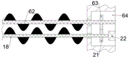
The mechanical structure schematic diagram of the pressure type foam garbage compressing and packaging equipment described with reference to fig. 1-4 includes a processor 10, a crushing chamber 20 is provided in the processor 10, a crushing mechanism 70 is provided in the crushing chamber 20, the crushing mechanism 70 includes a first crushing shaft 18 and a second crushing shaft 62 which are rotatable, and the foam garbage entering the crushing chamber 20 can be crushed through the rotation of the first crushing shaft 18 and the second crushing shaft 62;
a cleaning space 23 is arranged in the lower end wall of the crushing cavity 20, the left side of the upper end wall of the cleaning space 23 is communicated with the crushing cavity 20, a cleaning mechanism 71 is arranged in the cleaning space 23, the cleaning mechanism 71 comprises a rotatable rotary barrel 12, a cylindrical cavity 13 with an opening facing left is arranged in the rotary barrel 12, a discharge port 67 communicated with the cleaning space 23 is arranged on the right side of the lower end wall of the cylindrical cavity 13, filter holes are uniformly distributed in the rotary barrel 12, crushed foam garbage can enter the cylindrical cavity 13 and rotate along with the rotary barrel 12, fan blades 24 are arranged on the right side of the rotary barrel 12, and the fan blades 24 can blow out dust in the crushed foam garbage;
be equipped with working chamber 48 in the clean space 23 lower endwall, be equipped with compressing mechanism 72 in the working chamber 48, compressing mechanism 72 include with working chamber 48 left end wall fixed connection's collection piece 36, it is embedded to be equipped with electric plate 37 to collect the piece 36, be equipped with in the collection piece 36 and run through the collection chamber 38 of collecting the piece 36 up-and-down terminal surface, the crushing foam rubbish after getting rid of the dust can fall into collect in the chamber 38 by the collection, it is equipped with the compression piece 47 that can reciprocate to collect piece 36 upside, works as when collecting the foam rubbish in the chamber 38 and collecting certain quality, compression piece 47 descends and can compress the foam rubbish, electric plate 37 heats and can make the foam rubbish surface be in the molten condition for all foam rubbish adhesion become one, can be with the foam rubbish eduction gear of blocking after the compression is accomplished.
Advantageously, the crushing mechanism 70 further comprises a driving space 64 located in the right end wall of the crushing cavity 20, the right end wall of the driving space 64 is fixedly provided with a crushing motor 22, the left end face of the crushing motor 22 is rotatably provided with the first crushing shaft 18 with the left end rotatably connected with the left end wall of the crushing cavity 20, the first crushing shaft 18 in the driving space 64 is fixedly provided with a crushing gear 21, the rear side of the crushing motor 22 is provided with the second crushing shaft 62 rotatably connected with the right end wall of the driving space 64, the left end of the second crushing shaft 62 is rotatably connected with the left end wall of the crushing cavity 20, the second crushing shaft 62 in the driving space 64 is fixedly provided with an output gear 63, and the output gear 63 is meshed with the crushing gear 21.
Advantageously, the cleaning mechanism 71 further comprises a cleaning motor 28 fixedly connected to the right end wall of the cleaning space 23, a power shaft 29 is rotatably arranged on the left end surface of the cleaning motor 28, a driving pulley 27 is fixedly arranged on the power shaft 29, an output shaft 66 rotatably connected to the right end wall of the cleaning space 23 is arranged on the upper side of the cleaning motor 28, a driving pulley 25 is fixedly arranged on the output shaft 66, four fan blades 24 fixedly connected to the output shaft 66 are uniformly distributed on the left side of the driving pulley 25, the driving pulley 25 and the driving pulley 27 are in friction transmission through a belt 30, a supporting block 26 is fixedly arranged on the rear end wall of the cleaning space 23, a transmission shaft 32 penetrating through the supporting block 26 is rotatably arranged on the supporting block 26, the right end of the transmission shaft 32 is connected to the left end of the power shaft 29 through a universal wheel 31, and the rotary barrel 12 is fixedly arranged on the, the left end wall of the cleaning space 23 is fixedly provided with a guide plate 14, and the left side of the lower end wall of the cleaning space 23 is provided with a discharge cavity 65 communicated with the external space.
Beneficially, the compressing mechanism 72 includes a guide rod 34 fixedly disposed on a lower end wall of the cleaning space 23, the cleaning space 23 is communicated with the working chamber 48 through an exhaust duct 44, a vertical chamber 40 with an upward opening is disposed in the lower end wall of the exhaust duct 44, an electromagnet 39 is fixedly disposed on the lower end wall of the vertical chamber 40, a closing plate 42 is slidably disposed in the vertical chamber 40, a magnet 41 is fixedly disposed at the lower end of the closing plate 42, a moving groove 45 with a forward opening is disposed in the rear end wall of the working chamber 48, a moving spring 43 is fixedly disposed on the lower end wall of the moving groove 45, a moving block 46 slidably connected with the moving groove 45 is fixedly disposed at the upper end of the moving spring 43, and the compressing block 47 is fixedly disposed at the front end of the moving block 46;
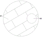
a supporting plate 51 and a compression motor 58 are fixedly arranged on the rear end wall of the working cavity 48, the compression motor 58 is positioned on the right side of the supporting plate 51, the upper end surface of the supporting plate 51 is rotatably provided with a top shaft 50, the top shaft 50 is fixedly provided with a transmission gear 49 and a cam 52, the cam 52 is positioned at the upper side of the transmission gear 49, a torsion shaft 59 is rotatably arranged in the lower end surface of the supporting plate 51 through a torsion spring 55, a rotary gear 57 is fixedly provided on the torsion shaft 59, a circular plate 61 is fixedly provided at the lower end of the torsion shaft 59, a hole 60 penetrating through the upper and lower end surfaces of the circular plate 61 is formed in the circular plate 61, a rotary shaft 54 is rotatably provided on the upper end surface of the compression motor 58, a bottom semicircular gear 56 and a top semicircular gear 53 are fixedly arranged on the rotating shaft 54, the bottom semicircular gear 56 is positioned at the upper side of the top semicircular gear 53, an outlet cavity 35 which is communicated with the working cavity 48 and the external space is arranged in the lower end wall of the working cavity 48.
Advantageously, the top half-round gear 53 can be rotated to engage with the driving gear 49.
Advantageously, said bottom semicircular gear 56 can be engaged with said rotary gear 57 after rotation.
Advantageously, the moving spring 43 and the torsion spring 55 are in a normal condition.
Advantageously, the processor 10 is embedded with an inclined block 15 with a left end located in the external space, an inclined cavity 17 is arranged in the inclined block 15, a conveyor belt 16 is arranged in the inclined cavity 17, and the foamed garbage can be conveyed into the crushing cavity 20 through the conveyor belt 16.
Sequence of mechanical actions of the whole device:
(1) the conveyor belt 16, the crushing motor 22 and the cleaning motor 28 are started, the foam garbage is poured onto the conveyor belt 16 and conveyed into the crushing cavity 20 through the conveyor belt 16, the crushing motor 22 drives the first crushing shaft 18 to rotate, the first crushing shaft 18 drives the crushing gear 21 to rotate, the output gear 63 is driven to rotate through the meshing of the crushing gear 21 and the output gear 63, the second crushing shaft 62 is driven to rotate along with the output gear 63, and the foam garbage is crushed through the rotation of the second crushing shaft 62 and the first crushing shaft 18.
(2) The crushed foam garbage enters the cylindrical cavity 13 through the guide of the guide plate 14, the cleaning motor 28 drives the power shaft 29 to rotate to drive the rotary barrel 12 and the driving belt wheel 27 to rotate, the crushed foam garbage rotates along with the rotary barrel 12, the driving belt wheel 27 drives the driving belt wheel 25 to rotate through the friction transmission of the belt 30, the fan blades 24 rotate along with the driving belt wheel 25, and dust in the crushed foam garbage is blown out of the discharge cavity 65.
(3) When the foam garbage in the collection cavity 38 accumulates a certain mass, the electromagnet 39 is electrified to generate magnetic force to repel the magnet 41, and the closing plate 42 is pushed to move upwards to block the discharge pipeline 44, so that the foam garbage in the collection cavity 38 is not increased any more.
(4) The compression motor 58 and the electric heating plate 37 are started, the compression motor 58 drives the rotating shaft 54 to rotate, the bottom semicircular gear 56 and the top semicircular gear 53 are driven to rotate, the transmission gear 49 is driven to rotate through the meshing of the top semicircular gear 53 and the transmission gear 49, the cam 52 rotates along with the transmission gear 49, the compression block 47 is pushed to descend, the foam garbage in the collection cavity 38 is compressed, and the electric heating plate 37 melts part of the foam garbage, so that the foam garbage is integrated.
(5) After the top semi-circular gear 53 is disengaged from the cam 52, the bottom semi-circular gear 56 is engaged with the rotating gear 57 to drive the rotating gear 57 to rotate, the circular plate 61 rotates along with the rotating gear 57 to drive the hole 60 to move to the lower side of the collecting cavity 38, and the foam garbage blocks fall to the rear side of the device through the hole 60 and the outlet cavity 35.
The above embodiments are merely illustrative of the technical ideas and features of the present invention, and the purpose thereof is to enable those skilled in the art to understand the contents of the present invention and implement the present invention, and not to limit the protection scope of the present invention. All equivalent changes and modifications made according to the spirit of the present invention should be covered within the protection scope of the present invention.