CN110352592B - Image forming apparatus and image forming method - Google Patents
Image forming apparatus and image forming method Download PDFInfo
- Publication number
- CN110352592B CN110352592B CN201880015067.9A CN201880015067A CN110352592B CN 110352592 B CN110352592 B CN 110352592B CN 201880015067 A CN201880015067 A CN 201880015067A CN 110352592 B CN110352592 B CN 110352592B
- Authority
- CN
- China
- Prior art keywords
- pixel
- image
- pixels
- section
- parallax
- Prior art date
- Legal status (The legal status is an assumption and is not a legal conclusion. Google has not performed a legal analysis and makes no representation as to the accuracy of the status listed.)
- Active
Links
- 238000000034 method Methods 0.000 title description 73
- 238000012545 processing Methods 0.000 claims abstract description 476
- 210000001747 pupil Anatomy 0.000 claims abstract description 272
- 238000003384 imaging method Methods 0.000 claims abstract description 256
- 238000002156 mixing Methods 0.000 claims description 175
- 239000000203 mixture Substances 0.000 claims description 100
- 238000004364 calculation method Methods 0.000 claims description 53
- 238000001514 detection method Methods 0.000 claims description 52
- 230000003287 optical effect Effects 0.000 claims description 28
- 230000002093 peripheral effect Effects 0.000 claims description 12
- 230000007423 decrease Effects 0.000 claims description 7
- 238000003672 processing method Methods 0.000 abstract description 5
- 230000008569 process Effects 0.000 description 49
- 239000013598 vector Substances 0.000 description 49
- 230000015654 memory Effects 0.000 description 45
- 238000010586 diagram Methods 0.000 description 34
- 238000012986 modification Methods 0.000 description 22
- 230000004048 modification Effects 0.000 description 22
- 238000007499 fusion processing Methods 0.000 description 21
- 238000006243 chemical reaction Methods 0.000 description 20
- 230000006870 function Effects 0.000 description 7
- 239000000284 extract Substances 0.000 description 6
- 238000004088 simulation Methods 0.000 description 6
- 230000008859 change Effects 0.000 description 5
- 238000004891 communication Methods 0.000 description 5
- 238000000605 extraction Methods 0.000 description 4
- 230000004044 response Effects 0.000 description 4
- 230000035945 sensitivity Effects 0.000 description 4
- 230000005540 biological transmission Effects 0.000 description 3
- 239000000470 constituent Substances 0.000 description 3
- 239000004065 semiconductor Substances 0.000 description 3
- 238000013459 approach Methods 0.000 description 2
- 230000002146 bilateral effect Effects 0.000 description 2
- 229910003460 diamond Inorganic materials 0.000 description 2
- 239000010432 diamond Substances 0.000 description 2
- 238000005401 electroluminescence Methods 0.000 description 2
- 238000005259 measurement Methods 0.000 description 2
- 238000012805 post-processing Methods 0.000 description 2
- 230000009467 reduction Effects 0.000 description 2
- 101100243951 Caenorhabditis elegans pie-1 gene Proteins 0.000 description 1
- 230000003044 adaptive effect Effects 0.000 description 1
- 238000013473 artificial intelligence Methods 0.000 description 1
- 230000001413 cellular effect Effects 0.000 description 1
- 235000005911 diet Nutrition 0.000 description 1
- 230000037213 diet Effects 0.000 description 1
- 238000006073 displacement reaction Methods 0.000 description 1
- 230000000694 effects Effects 0.000 description 1
- 230000004927 fusion Effects 0.000 description 1
- 239000004973 liquid crystal related substance Substances 0.000 description 1
- 238000011002 quantification Methods 0.000 description 1
- 238000013139 quantization Methods 0.000 description 1
- 238000005070 sampling Methods 0.000 description 1
- 238000006467 substitution reaction Methods 0.000 description 1
Images


Classifications
-
- H—ELECTRICITY
- H04—ELECTRIC COMMUNICATION TECHNIQUE
- H04N—PICTORIAL COMMUNICATION, e.g. TELEVISION
- H04N23/00—Cameras or camera modules comprising electronic image sensors; Control thereof
- H04N23/80—Camera processing pipelines; Components thereof
- H04N23/815—Camera processing pipelines; Components thereof for controlling the resolution by using a single image
-
- H—ELECTRICITY
- H04—ELECTRIC COMMUNICATION TECHNIQUE
- H04N—PICTORIAL COMMUNICATION, e.g. TELEVISION
- H04N13/00—Stereoscopic video systems; Multi-view video systems; Details thereof
- H04N13/20—Image signal generators
- H04N13/204—Image signal generators using stereoscopic image cameras
- H04N13/25—Image signal generators using stereoscopic image cameras using two or more image sensors with different characteristics other than in their location or field of view, e.g. having different resolutions or colour pickup characteristics; using image signals from one sensor to control the characteristics of another sensor
-
- G—PHYSICS
- G06—COMPUTING; CALCULATING OR COUNTING
- G06T—IMAGE DATA PROCESSING OR GENERATION, IN GENERAL
- G06T5/00—Image enhancement or restoration
- G06T5/50—Image enhancement or restoration using two or more images, e.g. averaging or subtraction
-
- H—ELECTRICITY
- H04—ELECTRIC COMMUNICATION TECHNIQUE
- H04N—PICTORIAL COMMUNICATION, e.g. TELEVISION
- H04N13/00—Stereoscopic video systems; Multi-view video systems; Details thereof
- H04N13/20—Image signal generators
- H04N13/204—Image signal generators using stereoscopic image cameras
- H04N13/207—Image signal generators using stereoscopic image cameras using a single 2D image sensor
- H04N13/232—Image signal generators using stereoscopic image cameras using a single 2D image sensor using fly-eye lenses, e.g. arrangements of circular lenses
-
- H—ELECTRICITY
- H04—ELECTRIC COMMUNICATION TECHNIQUE
- H04N—PICTORIAL COMMUNICATION, e.g. TELEVISION
- H04N23/00—Cameras or camera modules comprising electronic image sensors; Control thereof
- H04N23/10—Cameras or camera modules comprising electronic image sensors; Control thereof for generating image signals from different wavelengths
-
- H—ELECTRICITY
- H04—ELECTRIC COMMUNICATION TECHNIQUE
- H04N—PICTORIAL COMMUNICATION, e.g. TELEVISION
- H04N25/00—Circuitry of solid-state image sensors [SSIS]; Control thereof
- H04N25/10—Circuitry of solid-state image sensors [SSIS]; Control thereof for transforming different wavelengths into image signals
- H04N25/11—Arrangement of colour filter arrays [CFA]; Filter mosaics
- H04N25/13—Arrangement of colour filter arrays [CFA]; Filter mosaics characterised by the spectral characteristics of the filter elements
- H04N25/134—Arrangement of colour filter arrays [CFA]; Filter mosaics characterised by the spectral characteristics of the filter elements based on three different wavelength filter elements
-
- H—ELECTRICITY
- H04—ELECTRIC COMMUNICATION TECHNIQUE
- H04N—PICTORIAL COMMUNICATION, e.g. TELEVISION
- H04N25/00—Circuitry of solid-state image sensors [SSIS]; Control thereof
- H04N25/40—Extracting pixel data from image sensors by controlling scanning circuits, e.g. by modifying the number of pixels sampled or to be sampled
- H04N25/46—Extracting pixel data from image sensors by controlling scanning circuits, e.g. by modifying the number of pixels sampled or to be sampled by combining or binning pixels
-
- H—ELECTRICITY
- H04—ELECTRIC COMMUNICATION TECHNIQUE
- H04N—PICTORIAL COMMUNICATION, e.g. TELEVISION
- H04N25/00—Circuitry of solid-state image sensors [SSIS]; Control thereof
- H04N25/60—Noise processing, e.g. detecting, correcting, reducing or removing noise
-
- H—ELECTRICITY
- H04—ELECTRIC COMMUNICATION TECHNIQUE
- H04N—PICTORIAL COMMUNICATION, e.g. TELEVISION
- H04N25/00—Circuitry of solid-state image sensors [SSIS]; Control thereof
- H04N25/70—SSIS architectures; Circuits associated therewith
-
- H—ELECTRICITY
- H04—ELECTRIC COMMUNICATION TECHNIQUE
- H04N—PICTORIAL COMMUNICATION, e.g. TELEVISION
- H04N5/00—Details of television systems
- H04N5/222—Studio circuitry; Studio devices; Studio equipment
- H04N5/262—Studio circuits, e.g. for mixing, switching-over, change of character of image, other special effects ; Cameras specially adapted for the electronic generation of special effects
- H04N5/265—Mixing
-
- G—PHYSICS
- G06—COMPUTING; CALCULATING OR COUNTING
- G06T—IMAGE DATA PROCESSING OR GENERATION, IN GENERAL
- G06T2207/00—Indexing scheme for image analysis or image enhancement
- G06T2207/20—Special algorithmic details
- G06T2207/20212—Image combination
- G06T2207/20216—Image averaging
-
- G—PHYSICS
- G06—COMPUTING; CALCULATING OR COUNTING
- G06T—IMAGE DATA PROCESSING OR GENERATION, IN GENERAL
- G06T2207/00—Indexing scheme for image analysis or image enhancement
- G06T2207/20—Special algorithmic details
- G06T2207/20228—Disparity calculation for image-based rendering
Landscapes
- Engineering & Computer Science (AREA)
- Multimedia (AREA)
- Signal Processing (AREA)
- Physics & Mathematics (AREA)
- General Physics & Mathematics (AREA)
- Theoretical Computer Science (AREA)
- Spectroscopy & Molecular Physics (AREA)
- Studio Devices (AREA)
- Automatic Focus Adjustment (AREA)
- Focusing (AREA)
- Transforming Light Signals Into Electric Signals (AREA)
Abstract
The present disclosure relates to an imaging apparatus and an imaging method, and an image processing apparatus and an image processing method capable of capturing a high-resolution image by effectively using respective pixel signals of a plurality of pixels for which pupil division is performed directly below a microlens. The parallax is detected in units of pupils based on respective pixel values of a plurality of divided pixels for which pupil division is performed, the pixel values of the plurality of divided pixels are summed in units of pupils to obtain a total pixel value, and the pixel values of the divided pixels and the total pixel value are mixed with each other in units of the divided pixels according to the parallax. The present disclosure is applicable to an image forming apparatus.
Description
Technical Field
The present disclosure relates to an imaging apparatus and an imaging method, and an image processing apparatus and an image processing method, and more particularly, to an imaging apparatus and an imaging method, and an image processing apparatus and an image processing method, each capable of capturing a high-resolution image.
Background
There has been proposed an imaging apparatus which defines a pair of left and right pixels directly below one microlens by pupil division and acquires a parallax image using pixel values of the left and right pixels to measure a distance based on the parallax image (see patent document 1).
According to the imaging apparatus described in patent document 1 determined above, a pixel signal corresponding to an average value of pixel values of a plurality of pixels divided directly below a microlens is used as a signal indicating a pixel value of one pixel constituting an image to be captured to generate the image to be captured.
[ list of references ]
[ patent document ]
[ patent document 1]
JP2012-029194A
Disclosure of Invention
[ problem ] to
However, when an image is generated using the average value of the pixel values of the left and right pixels as one pixel regardless of whether or not a focus exists on each pixel of the imaging device, only a blurred image having a resolution lower than the original resolution of the sensor can be acquired.
The present disclosure developed in consideration of these circumstances realizes the capture of a high-resolution image particularly by effectively using respective pixel signals of a plurality of pixels defined by pupil division directly below the microlens.
[ solution of problem ]
An image forming apparatus according to an aspect of the present disclosure is an image forming apparatus including: an imaging device that includes a plurality of divided pixels defined by pupil division and captures an image; a parallax detection unit that detects parallax between the divided pixels in units of pupils; and a processing unit that performs processing on pixel values of a plurality of divided pixels defined by pupil division, the processing being performed in units of pupils and according to parallax.
The processing unit may include: a summing section that calculates an average value of pixel values of the plurality of divided pixels in units of pupils, and specifies the average value as a summed pixel value; and a pixel value mixing processing section that mixes the pixel values of the divided pixels with the summed pixel value according to the parallax.
The imaging apparatus may further include a pixel value mixing ratio calculation section that calculates a pixel value mixing ratio for mixing the pixel values of the divided pixels with the summed pixel value according to the parallax. The pixel value mixing processing section may mix the pixel values of the divided pixels with the summed pixel value at a pixel value mixing ratio calculated according to the parallax.
The pixel value mixture ratio calculation section may calculate a pixel value mixture ratio that increases the proportion of the summed pixel values as the parallax increases, and calculate a pixel value mixture ratio that increases the proportion of the pixel values of the divided pixels as the parallax decreases.
The imaging device may include a first imaging device and a second imaging device. The first imaging device may include RGB pixels arranged in a predetermined color arrangement in units of pupils. The second imaging device may include only white pixels. The parallax detection section may include: a first parallax detecting section that detects a first parallax in units of pupils based on a pixel value of each of the divided pixels captured by the first imaging device, and a second parallax detecting section that detects a second parallax in units of pupils based on a pixel value of each of the divided pixels captured by the second imaging device. The summing section may include: a first summing section that sums pixel values of the plurality of divided pixels captured by the first imaging device in units of pupils to designate an average value of the summed pixel values as a first summed pixel value, and a second summing section that sums pixel values of the plurality of divided pixels captured by the second imaging device in units of pupils to designate an average value of the summed pixel values as a second summed pixel value. The pixel value mixing processing section may include: a first mixing processing section that mixes the pixel values of the divided pixels captured by the first imaging device with the first summed pixel values according to the first parallax, and a second mixing processing section that mixes the pixel values of the divided pixels captured by the second imaging device with the second summed pixel values according to the second parallax. The processing unit may include: and a luminance blend processing unit that blends the first luminance of the pixel values blended by the first blend processing unit and the second luminance of the pixel values blended by the second blend processing unit.
The luminance mixing processing section may mix the first luminance of the pixel values mixed by the first mixing processing section and the second luminance of the pixel values mixed by the second mixing processing section at a predetermined luminance mixing ratio.
The imaging apparatus may further include a luminance mixture ratio calculation section that calculates a luminance mixture ratio based on the first luminance and the second luminance.
The luminance mixture ratio calculation section may include: a difference luminance mixture ratio calculation section that calculates a difference luminance mixture ratio based on a difference between the first luminance and the second luminance; a dynamic range luminance mixture ratio calculation section that calculates, for the second luminance, a dynamic range luminance mixture ratio based on a dynamic range obtained from the maximum value and the minimum value of the peripheral pixels of each pixel; and a selection section that selects a smaller ratio from the difference luminance mixing ratio and the dynamic range luminance mixing ratio as the luminance mixing ratio.
The image forming apparatus may further include: an optical unit that condenses light entering the imaging device in a stage before the imaging device; a focus control unit that controls a focus position at which the light is condensed by controlling the optical unit, and outputs information associated with a position as a reference of the focus position; and a depth detection unit that detects a depth and generates a depth map. The pixel value mixture ratio calculation section may calculate, in a region of the depth map which is included in the depth map and whose depth is substantially equal to the depth of the position, a pixel mixture ratio which mixes the summed pixel value with the pixel values of the divided pixels in the region, the region being a region regarded as having substantially zero parallax.
The processing unit may include an estimating section that estimates a pixel value of the divided pixel from a sum of products of a predetermined number of coefficients obtained by predetermined learning and pixel values of respective pixels included in an estimation tap including a pixel group having a predetermined positional relationship with the divided pixel, based on the disparity. The processing unit may output the estimation result received from the estimation section as a processing result obtained by performing processing in units of pupils according to the parallax.
The image forming apparatus may further include: a class classification section that classifies each of the divided pixels into a class based on a class tap including a pixel group having a predetermined positional relationship with the divided pixel and the parallax detected by the parallax detection section; and a coefficient set storage unit that stores a coefficient set including a predetermined number of coefficients for each of the categories. The estimation section may read a coefficient set corresponding to the class established by the class classification section from the coefficient set storage section, and estimate the pixel value of the divided pixel based on a sum of products of respective coefficients in the coefficient set and pixel values of respective pixels included in an estimation tap including a pixel group having a predetermined positional relationship with the divided pixel.
The predetermined learning may be the following learning: the method includes using a teacher image including a high-resolution image and a student image generated by distorting the teacher image based on parallax in units of pupils and reducing image quality of the teacher image, and determining coefficients such that an error between a pixel value at a pixel position corresponding to the teacher image and a result of a sum of products of a predetermined number of coefficients and pixel values of pixels included in estimation taps including a pixel group having a predetermined positional relationship with each pixel in the student image becomes statistically minimum.
The imaging apparatus may further include a noise removing section that removes noise based on the parallax according to pixel values of the plurality of divided pixels processed based on the parallax in units of pupils by the processing unit.
During scaling of a part of an image, pixel values of pixels in a range in which scaling can be specified include pixel values of a plurality of divided pixels which are defined by pupil division and processed according to parallax in units of pupils by a processing unit.
The imaging device may include an image surface phase difference type imaging device.
The divided pixels of the imaging device may include divided pixels defined by pupil division in the horizontal direction.
The imaging device may comprise a light field camera.
An imaging method according to an aspect of the present disclosure includes the steps of: detecting a parallax between a plurality of divided pixels of an imaging device that captures an image, the divided pixels included in the imaging device being defined by pupil division; and performing processing on pixel values of a plurality of divided pixels defined by pupil division, the processing being performed in units of pupils and according to parallax.
An image processing apparatus according to an aspect of the present disclosure includes: an imaging device that includes a plurality of divided pixels defined by pupil division and captures an image; a parallax detection unit that detects parallax between the divided pixels in units of pupils; and a processing unit that performs processing on pixel values of a plurality of divided pixels defined by pupil division, the processing being performed in units of pupils and according to parallax.
An image processing method according to an aspect of the present disclosure includes the steps of: detecting a parallax between a plurality of divided pixels of an imaging device that captures an image, the divided pixels included in the imaging device being defined by pupil division; and performing processing on pixel values of a plurality of divided pixels defined by pupil division, the processing being performed in units of pupils and according to parallax.
According to an aspect of the present disclosure, a plurality of divided pixels defined by pupil division are set to capture an image. The parallax between the divided pixels is detected in units of pupils. Processing corresponding to parallax is performed in units of pupils with respect to pixel values of a plurality of divided pixels defined by pupil division.
[ advantageous effects of the invention ]
According to an aspect of the present disclosure, a high-resolution image can be captured by effectively using respective pixel signals of a plurality of pixels defined by pupil division directly below a microlens.
Drawings
[ FIG. 1]
Fig. 1 is a diagram illustrating an outline of an image forming apparatus according to the present disclosure.
[ FIG. 2]
Fig. 2 is a diagram illustrating a configuration example of an image forming apparatus according to the first embodiment.
[ FIG. 3]
Fig. 3 is a diagram illustrating a configuration example of the image processing unit in fig. 1.
[ FIG. 4]
Fig. 4 is a diagram illustrating a configuration example of the scaling processing section in fig. 3.
[ FIG. 5]
Fig. 5 is a flowchart illustrating image processing performed by the image processing unit in fig. 3.
[ FIG. 6]
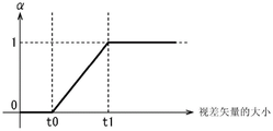
Fig. 6 is a diagram illustrating a method of determining the mixing ratio α based on the magnitude of the disparity vector.
[ FIG. 7]
Fig. 7 is a flowchart for explaining the scaling process performed by the scaling processing section in fig. 4.
[ FIG. 8]
Fig. 8 is a flowchart for explaining the scaling process performed by the scaling processing section in fig. 4.
[ FIG. 9]
Fig. 9 is a diagram illustrating a configuration example of an image processing unit according to a first modification of the first embodiment.
[ FIG. 10]
Fig. 10 is a flowchart illustrating a noise removal process performed by the image processing unit in fig. 9.
[ FIG. 11]
Fig. 11 is a view illustrating an outline of an image forming apparatus according to a second modification of the first embodiment.
[ FIG. 12]
Fig. 12 is a diagram illustrating a configuration example of an image forming apparatus according to a second modification of the first embodiment.
[ FIG. 13]
Fig. 13 is a diagram illustrating a configuration example of the image processing unit in fig. 12.
[ FIG. 14]
Fig. 14 is a flowchart illustrating image processing performed by the image processing unit in fig. 12.
[ FIG. 15]
Fig. 15 is a diagram illustrating a configuration example of an image forming apparatus according to a third modification of the first embodiment.
[ FIG. 16]
Fig. 16 is a diagram illustrating a configuration example of the scaling processing section in fig. 15.
[ FIG. 17]
Fig. 17 is a flowchart illustrating the learning process.
[ FIG. 18]
Fig. 18 is a flowchart for explaining the scaling process performed by the scaling processing section in fig. 15.
[ FIG. 19]
Fig. 19 is a diagram illustrating a configuration example of an image forming apparatus according to the second embodiment.
[ FIG. 20]
Fig. 20 is a diagram illustrating a configuration example of the image processing unit in fig. 19.
[ FIG. 21]
Fig. 21 is a diagram illustrating an example of the arrangement of the fusion processing unit in fig. 20.
[ FIG. 22]
Fig. 22 is a diagram illustrating a configuration example of the mixing ratio calculation section in fig. 21.
[ FIG. 23]
Fig. 23 is a flowchart illustrating image processing performed by the image processing unit in fig. 20.
[ FIG. 24]
Fig. 24 is a flowchart for explaining the fusion process executed by the fusion processing section in fig. 20.
[ FIG. 25]
Fig. 25 is a flowchart illustrating a mixing ratio calculation process executed by the mixing ratio calculation section in fig. 21.
[ FIG. 26]
Fig. 26 is a diagram illustrating a configuration example of an image processing unit according to a first modification of the second embodiment.
[ FIG. 27]
Fig. 27 is a diagram illustrating a configuration example of an image processing unit according to a second modification of the second embodiment.
[ FIG. 28]
Fig. 28 is a flowchart illustrating image processing performed by the image processing unit in fig. 27.
[ FIG. 29]
Fig. 29 is a diagram illustrating a configuration example of an imaging apparatus according to a third modification of the second embodiment.
[ FIG. 30]
Fig. 30 is a diagram illustrating a difference in resolution between the imaging devices in fig. 29.
[ FIG. 31]
Fig. 31 is a diagram illustrating a configuration example of an imaging apparatus according to a fourth modification of the second embodiment.
[ FIG. 32]
Fig. 32 is a diagram illustrating a configuration example of an imaging apparatus according to the third embodiment.
[ FIG. 33]
Fig. 33 is a diagram illustrating a configuration example of an image processing unit corresponding to the imaging apparatus in fig. 32.
[ FIG. 34]
Fig. 34 is a diagram illustrating an outline of an image processing unit according to the fourth embodiment.
[ FIG. 35]
Fig. 35 is a diagram illustrating a configuration example of an image processing unit according to the fourth embodiment.
[ FIG. 36]
Fig. 36 is a flowchart illustrating image processing performed by the image processing unit in fig. 35.
[ FIG. 37]
Fig. 37 is a diagram illustrating a configuration example of a general-purpose personal computer.
Detailed Description
Preferred embodiments according to the present disclosure will be described in detail below with reference to the accompanying drawings. Note that constituent elements having substantially the same functional configuration are given the same reference numerals in the present specification and the drawings, and the same description is not repeated.
Modes for carrying out the present disclosure (hereinafter referred to as embodiments) will be described below. Note that description will be made in the following order.
1. Outline of image forming apparatus of the present disclosure
2. First embodiment
2-1. first modification of the first embodiment
2-2. second modification of the first embodiment
2-3. third modification of the first embodiment
3. Second embodiment
3-1. first modification of the second embodiment
3-2. second modification of the second embodiment
3-3. third modification of the second embodiment
3-4. fourth modification of the second embodiment
4. Third embodiment
5. Fourth embodiment
6. Examples of software execution
<1. overview of image forming apparatus of the present disclosure >
Before describing the image forming apparatus, an outline of the image forming apparatus to which the technique of the present disclosure has been applied will be first touched.
For example, the imaging apparatus according to the present disclosure includes a full image surface phase difference type imaging device as shown in the upper left part of fig. 1.
The imaging device IS of the full image surface phase difference type in the upper left part of fig. 1 includes microlenses (on-chip lenses), not shown, each constituting a unit indicated by a broken line. The RGB pixels are arranged in units of a pixel P surrounded by a dotted line directly under one microlens. Each pixel in the upper left portion of fig. 1 is arranged in a Bayer (Bayer) array.
In addition, each pixel P is divided into two parts in the horizontal direction by pupil division. Each pixel P includes divided pixels PL and PR.
Note that the pixels P provided in units of one microlens surrounded by a dotted line within the imaging device IS in the upper left portion of fig. 1 will be referred to as pupil pixels P hereinafter, and the divided pixels will be referred to as divided pixels PL and PR. Therefore, the pupil pixel P includes a pair of divided pixels PL and PR.
The pixel signals are output in units of the divided pixels PL and PR. In this case, pixel signals of two pixels, which are divided pixels PL and PR in the horizontal direction, are obtained for the pupil pixel P covered by one microlens. Therefore, based on the phase difference between the pixel values resulting from the parallax between the split pixels PL and PR, distance measurement in units of pixels P can be achieved.
Therefore, the imaging device IS in the upper left part of fig. 1 can acquire a depth image (distance measurement image) in units of pupil pixels P.
In addition, in such a conventional configuration, an average value of pixel values of the divided pixels PL and PR is calculated for each pupil pixel P, a common pixel signal in units of the pupil pixels P is generated, and an image is generated using the pixel signal in units of the pupil pixels P.
Meanwhile, in general, in a case where the generated image is focused on the focal point, the images generated from the divided pixels PL and PR are substantially identical to each other. In the case where the generated image is not focused on the focal point (e.g., infinity), a deviation occurs according to the parallax between the split pixels PL and PR.
More specifically, in a state of focusing on the focal point, as shown in the upper middle part of fig. 1, an image AL1 generated from only the pixel signal of the divided pixel PL and an image AR1 generated from only the pixel signal of the divided pixel PR are captured.
In the case of the upper middle part of fig. 1, each of the images AL1 and AR1 is an image focused on a focal point, and thus becomes the same image as each other. Note that a broken line is given to the center of each of the images AL1 and AR1 to check whether there is a deviation. The golfer is present substantially at the center of each of the images AL1 and AR 1.
In contrast, in the case of focusing on infinity, as shown in the upper right part of fig. 1, an image AL2 generated only from the pixel signal of the divided pixel PL and an image AR2 generated only from the pixel signal of the divided pixel PR are captured.
In the case of the upper right part of fig. 1, each of the images AL2 and AR2 becomes an image focused on infinity. Therefore, a deviation occurs according to the parallax between the divided pixels PL and PR. Note that a broken line is given to the center of each of the images AL2 and AR2 to check whether there is a deviation. The golfer is present substantially at the center of the image AL2, but at a position shifted to the right in the image AR 2.
In consideration of such a difference, in a case of focusing on the focal point, as shown in the lower middle part of fig. 1, each of the divided pixels PR and PL forming the images AL1 and AR1 constitutes an image as an independent pixel signal. In this way, the resolution of the acquired image in the horizontal direction is twice the resolution of an image in the horizontal direction generated from pupil pixels each including one pixel. Particularly when the zoom image is generated not by optical zoom but by so-called digital zoom that processes pixel signals, a high-quality zoom image can be formed by using high-resolution pixel signals.
On the other hand, in the case of focusing on infinity, the split pixels PR and PL forming the images AL2 and AR2 constitute images at positions different from each other, and cannot be used as respective independent pixel signals. Therefore, similarly to the conventional case, the average value of the pixel values of the divided pixels PL and PR is used as the common pixel value of the divided pixels PL and PR in units of pupil pixels to generate an image including pupil pixels each corresponding to one pixel, as shown in the lower right part of fig. 1.
Therefore, according to the imaging apparatus of the present disclosure provided based on the foregoing principle, high resolution is achieved by independently using pixel signals in units of divided pixels PL and PR for pixels in a region close to the focal point within an image. For the pixels in the other regions, the average value of the divided pixels PL and PR calculated by adding (summing) the divided pixels PL and PR and dividing the sum by the number of pixels is used as a common pixel signal in pupil pixel units. Therefore, by effectively using respective pixel signals of a plurality of divided pixels defined by pupil division directly below the microlens, a high-resolution image can be captured.
<2> first embodiment
Next, a configuration example of an image forming apparatus according to a first embodiment of the present disclosure will be described with reference to the block diagram of fig. 2. Note that the right-side portion of fig. 2 is a block diagram depicting a configuration example of the imaging apparatus according to the first embodiment of the present disclosure, and the left-side portion of fig. 2 is a front view of the imaging device 32 facing the incident direction of incident light. As described above, the imaging apparatus in fig. 2 captures a high-resolution image by effectively using respective pixel signals of a plurality of divided pixels each defined by pupil division directly below the microlens.
The imaging apparatus 11 in fig. 2 includes: an optical unit 31, the optical unit 31 including a lens group and the like; and an imaging device 32, the imaging device 32 corresponding to the imaging device IS in fig. 1 and including pupil pixels P, each of which includes divided pixels PL and PR defined by pupil division and arranged in a two-dimensional array directly below the microlens ML. The imaging device 11 further includes an image processing unit 33. The imaging apparatus 11 further includes a frame memory 34, a display unit 35, a recording unit 36, an operation unit 37, and a power supply unit 38. The image processing unit 33, the frame memory 34, the display unit 35, the recording unit 36, the operation unit 37, and the power supply unit 38 are connected to each other via a bus 39.
The optical unit 31 receives incident light (image light) from a subject and forms an image on an imaging surface of the imaging device 32. The imaging device 32 converts the light amount of incident light of an image formed on the imaging surface by the optical unit 31 into an electric signal in units of pixels, and outputs the electric signal as a pixel signal. As shown in the left part of fig. 2, the imaging device 32 includes pupil pixels P arranged in an array on an imaging surface. Each pupil pixel P converts the light amount of incident light into an electric signal in units of pixels, and outputs the electric signal as a pixel signal.
The imaging device 32 further includes a microlens ML that is provided for each pupil pixel P and transmits light in the incident direction of incident light in units of pupil pixels P. Each microlens ML converges light in units of pupil pixels P. The split pixels PL and PR are disposed directly below each microlens ML in the transmission direction of incident light. The pair of split pixels PL and PR constitutes a pupil pixel P. In addition, an RGB color filter, not shown, is provided for each pupil pixel P. For example, the pupil pixels are arranged in a bayer array in units of 2 pixels × 2 pixels. Note that the color arrangement of the pixels may be other arrangements.
The image processing unit 33 performs various types of image processing on the pixel signals output from the imaging device 32, and outputs the processed pixel signals. When performing various types of image processing on the image signal output from the imaging device 32, the image processing unit 33 temporarily stores an image using the frame memory 34 as necessary.
The display unit 35 is, for example, a panel-type display device such as a liquid crystal panel and an organic EL (electro luminescence) panel, and displays a moving image or a still image captured by the imaging device 32. The recording unit 36 records the moving image or the still image captured by the imaging device 32 in a recording medium such as a hard disk and a semiconductor memory.
The operation unit 37 issues operation commands of various functions performed by the imaging apparatus 11 under operation of the user. The power supply unit 38 supplies various types of electric power as necessary as operating electric power of these power supply targets to the image processing unit 33, the frame memory 34, the display unit 35, the recording unit 36, and the operation unit 37.
Note that, for example, the imaging device 11 may be applied to various types of electronic devices, for example, imaging devices such as a digital still camera and a digital video camera, a cellular phone having an imaging function, and other types of devices having an imaging function.
< example of configuration of image processing unit in FIG. 2>
Next, a configuration example of the image processing unit 33 will be described with reference to the block diagram in fig. 3.
The image processing unit 33 includes a parallax detection section 51, a determination section 52, and a scaling processing section 53.
The parallax detection section 51 detects a parallax between a pair of divided pixels PL and PR constituting the pupil pixel P as a parallax vector based on pixel signals of the divided pixels PL and PR, and outputs the detected parallax vector to the determination section. More specifically, the disparity vector is an index indicating disparity which is a deviation between the above-described divided pixels PL and PR. As the parallax vector becomes smaller, the parallax between the divided pixels PL and PR on the pupil pixel P decreases, and the possibility that the pupil pixel P is closer to the focus is high. In contrast, as the disparity vector becomes larger, the disparity between the divided pixels PL and PR increases.
The determination section 52 calculates a mixing ratio of the non-summed value to the summed pixel value based on the magnitude of the disparity vector, and outputs the mixing ratio to the scaling processing section 53. The non-summed pixel value is a value obtained in a case where the divided pixels PL and PR are processed into individual pixel signals in units of divided pixels by the scaling processing section 53, and the summed pixel value is a value obtained in a case where the pixel signals are processed in units of pupil pixels P by replacing the pixel values of the divided pixels PL and PR with the average value of the pixel values of the divided pixels PL and PR summed in units of pupil pixels P.
More specifically, as described above, the pupil pixel P having a smaller parallax vector is regarded as a pixel having a smaller parallax and closer to the focus. In this case, the pixel signals in units of the divided pixels PL and PR serving as independent non-summed pixel values are high-resolution pixel signals.
In contrast, the pupil pixel P having a larger parallax vector is considered as a pixel having a larger parallax between the divided pixels PL and PR and not close to the focus. In this case, the average value of the pixel signals summed in units of the divided pixels PL and PR is calculated, and the pixel signals of the divided pixels PL and PR are replaced with the calculated average value to use the average value as a summed pixel value equalized in units of the pupil pixel P.
As described above, in the region near the focus within the image, a high-resolution image is generated by processing the pixel signals into the non-summed pixel values that are independently used in units of the divided pixels PL and PR. On the other hand, in the region other than the focal point, the divided pixels PL and PR are each processed into a summed pixel value that is an average value of the divided pixels PL and PR in units of the pupil pixel P and replaces the divided pixels PL and PR, so that the pixel signals in units of the divided pixels PL and PR are effectively used, and a lossless high-resolution image is generated.
Note that an image including independent pixel signals in units of the split pixels PL and PR will be referred to as a split pixel image hereinafter. In addition, an image generated from pixel signals each obtained from the same average value of the divided pixels PL and PR replacing the image signals of the divided pixels PL and PR for each pupil pixel P will be referred to as a pupil pixel image.
The pupil pixel image here is generated from the same pixel value corresponding to the average value of the respective pixel values of the divided pixels PL and PR constituting the pupil pixel P instead of the pixel values of the divided pixels PL and PR. In this case, the substantially smallest pixel becomes a unit of the pupil pixel P. Therefore, the divided pixel image becomes an image having a resolution in the horizontal direction that is substantially twice the resolution of the pupil pixel image in the horizontal direction. However, the resolution in the vertical direction is equal for both the pupil pixel image and the divided pixel image.
Therefore, the determination portion 52 calculates, in units of the divided pixels PL and PR, a mixing ratio for mixing pixel values of a pupil pixel image including a pixel signal that is an average value of the divided pixels PL and PR and pixel signals of the divided pixels PL and PR that are independently used without change based on the magnitude of the parallax vector in units of the divided pixels PL and PR. The determination section 52 outputs the calculated mixing ratio to the scaling processing section 53.
The scaling processing section 53 performs demosaicing on each pupil pixel image of RGB, and also performs demosaicing on the divided pixel images of RGB.
Thereafter, the scaling processing section 53 mixes the divided pixel images of RGB with the pupil pixel images of RGB in units of the divided pixels PL and PR at a mixing ratio α (0 ≦ α ≦ 1) as a result of the determination from the determination section 52, and outputs the mixed image as an RGB image and a scaled image. Note that the detailed configuration of the scaling processing section 53 will be described below with reference to fig. 4. In the case where the mixing ratio α is switched to 0 or 1, the divided pixel images of RGB and the pupil pixel images of RGB are completely switched in accordance with the value of the mixing ratio α. In addition, in the case where the mixing ratio α varies in the range of 0 to 1, mixing is performed such that the divided pixel images of RGB have a greater weight when the mixing ratio α approaches 0, and conversely, such that the pupil pixel images of RGB have a greater weight when the mixing ratio α approaches 1.
< example of configuration of scaling processing section in fig. 3>
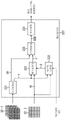
Next, a configuration example of the scaling processing section 53 will be described with reference to the block diagram of fig. 4.
The scaling processing section 53 includes a summing section 71, a frame memory 72, demosaic processing sections 73-1 and 73-2, frame memories 74-1 and 74-2, and a mixing processing section 75.
The summing section 71 sums the pixel signals of the divided pixels PL and PR supplied from the imaging device 32 in units of divided pixels to calculate an average value of the summed pixel signals, replaces the pixel signals of the divided pixels PL and PR with the calculated average value, and causes the frame memory 72 to store the pixel signals as the replacement.
More specifically, the summing section 71 calculates an average value of the pixel signals in units of the divided pixels PR and PL, and substitutes the calculated pixel signals for the respective pixel signals of the divided pixels PR and PL. In other words, the summing section 71 converts the pixel signals of the divided pixels PR and PL into an average value in units of pupil pixels to obtain pixel signals in units of pupil pixels. Therefore, in the RGB pupil pixel image having the same pixel signal for each pupil pixel, the divided pixels PL and PR have the same pixel signal for each pupil pixel.
The demosaic processing section 73-1 performs a demosaic process on a divided pixel image including the individual pixel signals in units of the divided pixels PL and PR and received from the imaging device 32, generates a divided pixel image for each of RGB, and causes the frame memory 74-1 to store the generated image.
The demosaic processing portion 73-2 performs demosaic processing on pupil pixel images including the same average value in units of pupil pixels P stored in the frame memory 72 as pixel signals in units of divided pixels PL and PR, generates pupil pixel images for each RGB, and causes the frame memory 74-2 to store the generated pupil pixel images.
The mixing processing section 75 mixes the RGB divided pixel images stored in the frame memories 74-1 and 74-2 with the RGB pupil pixel image in units of divided pixels and at the mixing ratio α supplied from the determination section 52, causes the frame memory 76 to store the mixed image as an RGB image or a scaled image, and outputs the mixed image when one frame image is generated. When scaling is not specified, the blend processing unit 75 outputs all pixels blended in units of divided pixels. When scaling is designated, the blending processing unit 75 outputs only pixels within a designated range of scaling of all pixels blended in units of divided pixels.
< image processing by image processing Unit in FIG. 3>
Next, image processing performed by the image processing unit 33 in fig. 3 will be described with reference to the flowchart in fig. 5.
In step S11, the imaging device 32 captures an image and outputs pixel signals of the captured image in units of divided pixels. In this way, an image including pixel values in units of the divided pixels PL and PR is input to the image processing unit 33.
In step S12, the parallax detection section 51 sets any one of unprocessed pixels as a processing target pixel in units of pupil pixels.
In step S13, the parallax detection section 51 obtains a parallax vector using the pixel values of the left divided pixel PL and the right divided pixel PR that constitute the pupil pixel P corresponding to the processing target pixel, and outputs the obtained parallax vector to the determination section 52 as the parallax vector of the processing target pixel.
More specifically, the parallax detecting section 51 calculates a parallax vector by ordinary optical flow estimation. Examples of the method using the ordinary optical flow estimation include a method using block matching and a KLT (Kanade Lucas-Tomasi) method.
Examples of the method using block matching include a method of searching for a similar region in units of blocks using cost values such as SSD (sum of squared differences) defined by the following equation (1) and SAD (sum of absolute differences) defined by the following equation (2).
[ mathematical formula 1]
ε=∫w[J(x+d)-I(x)]2dx...(1)
[ mathematical formula 2]
ε=∫w|J(x+d)-I(x)|dx...(2)
In these equations, ε is a cost value, w is a search region, J is a reference image, I is a standard image, x is the coordinates of a pixel corresponding to a processing target, and d is a displacement.
The disparity vector is obtained using two pixels constituting the similar region obtained in this way.
For more details on the KLT method, please refer to "An Iterative Image Registration Technique with An Application to Stereo Vision" at page 674-679 of the International Association of Artificial Intelligence conference in 1981 by Bruce D.Lucas and Takeo Kanade or "Detection and Tracking of Point diets" at the University of Kanekum (Carlo Mellon University) technical report CMU-CS-91-132 in 1991 at month 4 by Carlo Tomasi and Takeo Kanade.
In step S14, the determination section 52 calculates a mixing ratio α for mixing the pixel values of the pixels of the divided pixel image and the pupil pixel image of the processing target pixel based on the magnitude of the parallax vector of the processing target pixel, and causes the scaling processing section 53 to store the calculated mixing ratio α.
For example, the determination section 52 calculates the mixing ratio α based on the magnitude of the disparity vector using the relationship shown in fig. 6.
Fig. 6 shows a function having a horizontal axis indicating the magnitude of the disparity vector and a vertical axis indicating the mixing ratio α.
More specifically, when the magnitude of the disparity vector is smaller than the threshold value t0, the determination section 52 sets the mixing ratio α to 0. When the magnitude of the disparity vector is in the range from the threshold t0 to the threshold t1, the determination section 52 sets the mixing ratio α to a value in the range of 0 to 1 that is proportional to the magnitude of the disparity vector. When the magnitude of the disparity vector is larger than the threshold value t1, the determination section 52 sets the mixing ratio α to 1. Note that the thresholds t1 and t2 may be set to any value. Accordingly, as shown in fig. 6, as the magnitude of the disparity vector decreases, the determination section 52 decreases the mixing ratio α. As the magnitude of the disparity vector increases, the determination section 52 increases the mixing ratio α.
In step S15, the parallax detection section 51 determines whether any pupil pixel remains unprocessed. In the case where any pupil pixel has not been processed yet, the process returns to step S12. More specifically, the processing from step S12 to step S15 is repeated until there are no pupil pixels that have not yet been processed. The mixing ratio α is sequentially calculated in units of pupil pixels and stored in the mixing processing section 75 of the scaling processing section 53.
In the case where there is no pupil pixel not yet processed in step S15, the process advances to step S16.
In step S16, the scaling processing section 53 performs scaling processing using the divided pixels PL and PR to generate a divided pixel image and a pupil pixel image, then mixes the divided pixel image with the pupil pixel image at a mixing ratio α set in pupil pixel units, and outputs the mixed image to end the processing.
< scaling processing by scaling processing section in FIG. 4>
The scaling processing performed by the scaling processing section 53 in fig. 4 will be described herein with reference to the flowchart in fig. 7.
In step S31, the summing section 71 sums the pixel values of the left divided pixel PL and the right divided pixel PR supplied from the imaging device 32 in pupil pixel units to calculate an average value of the pixel values, replaces each of the divided pixels PL and PR with the calculated average value to generate a pupil pixel image, and causes the frame memory 72 to store the generated pupil pixel image. Note that, as described above, the pupil pixel image has a pixel value corresponding to the average value of the divided pixels PL and PR in units of the pupil pixel P. Therefore, the divided pixels PL and PR of the pupil pixel image each have the same pixel value in units of the pupil pixel P, but the pixel value itself is stored for each of the divided pixels PL and PR.
In step S32, the demosaicing processing section 73-2 performs demosaicing on the pupil pixel images stored in the frame memory 72 in pupil pixel units, generates pupil pixel images of RGB, and causes the frame memory 74-2 to store the generated pupil pixel images of RGB.
In step S33, the demosaicing processing portion 73-1 performs demosaicing on the split pixel images in units of the split pixels PL and PR supplied from the imaging device 32, generates the split pixel images of RGB, and causes the frame memory 74-1 to store the generated split pixel images of RGB.
In step S34, the blend processing section 75 sets any one of unprocessed pixels as a processing target pixel in pupil pixel units.
In step S35, the blend processing section 75 blends the pixel value of the left divided pixel PL corresponding to the pupil pixel P as the processing target pixel in the RGB divided pixel image with the pixel value of the divided pixel PL constituting the pupil pixel P as the processing target pixel in the RGB pupil pixel image at the blend ratio α, and causes the frame memory 76 to store the blended pixel value as the pixel value of the left divided pixel of the processing target pixel. More specifically, for example, the mixing processing section 75 performs the calculation of the following equation (3), and causes the frame memory 76 to store the mixing result.
Imageout_L=α×ImageCOMB_L+(1-α)×ImageDIV_L… (3)
In the equation, α is a mixing ratio, ImageCOMB_LIs a pixel value, Image, of a left divided pixel PL corresponding to a pupil pixel P as a processing target pixel in an RGB pupil pixel ImageDIV_LIs a pixel value of a left divided pixel PL corresponding to a pupil pixel P as a processing target pixel in an RGB divided pixel Image, and Imageout_LIs the pixel value of the left divided pixel PL in the blend processing target pixel.
In step S36, the blend processing section 75 blends the pixel value of the right divided pixel PR corresponding to the pupil pixel P as the processing target pixel in the RGB divided pixel image with the pixel values of the divided pixels PR constituting the pupil pixel P as the processing target pixel in the RGB pupil pixel image at the blend ratio α, and causes the frame memory 76 to store the blended pixel value as the pixel value of the right divided pixel of the processing target pixel. More specifically, for example, the mixing processing section 75 performs the calculation of the following equation (4), and causes the frame memory 76 to store the mixing result.
Imageout_R=α×ImageCOMB_R+(1-α)×ImageDIV_R… (4)
In the equation, α is a mixing ratio, ImageCOMB_RIs a pixel value, Image, of the right divided pixel PR corresponding to a pupil pixel as a processing target pixel in the RGB pupil pixel ImageDIV_RIs a pixel value of the right divided pixel PR corresponding to a pupil pixel as a processing target pixel in the RGB divided pixel Image, and Imageout_RIs the pixel value of the right divided pixel PR in the blend processing target pixel.
In step S37, the blend processing section 75 determines whether any pupil pixel remains unprocessed. In the case where any pupil pixel has not been processed yet, the process returns to step S34. More specifically, similar processing is repeated until all the divided pixels PL and PR of the RGB divided pixel image and the RGB pupil pixel image are mixed at the mixing ratio α in pupil pixel units.
Subsequently, in a case where it is considered in step S37 that there are no pupil pixels yet to be processed, the process advances to step S38.
In step S38, the blend processing section 75 outputs the blended image stored in the frame memory 76. In this case, the range of the pixel signal output here is switched according to the zoom magnification and the zoom center position.
The process depicted in fig. 8 is realized by executing the aforementioned process.
More specifically, as shown in fig. 8, the demosaicing processing section 73-1 performs demosaicing on the split pixel image IPD received from the imaging device 32 in units of split pixels, and thus an R split pixel image PDR, a G split pixel image PDG, and a B split pixel image PDB corresponding to RGB are generated and stored in the frame memory 74-1.
On the other hand, the summing section 71 sums the pixel signals of the split pixels PL and PR in units of pupil pixels P in the split pixel image IPD received from the imaging device 32, calculates an average value of the summed pixel signals, and replaces each of the pixel values of the split pixels PL and PR with the calculated average value in units of pupil pixels to generate a pupil pixel image IPC.
Subsequently, the demosaicing processing section 73-2 performs demosaicing on the pupil pixel image IPC in units of pupil pixels, and thus an R pupil pixel image PCR, a G pupil pixel image PCG, and a B pupil pixel image PCB, which correspond to RGB, respectively, are generated and stored in the frame memory 74-2.
The blending processing section 7 further blends the pixel values of the split pixels PL and PR in the pupil pixel image with the pixel values of the split pixels PL and PR in the split pixel image for each of RGB for a blending ratio α set in pupil pixel units for the split pixels PL and PR in pupil pixel units, and outputs the blended image as output images OPR, OPG, and OPB including the split pixel images of the corresponding RGB, respectively.
In the case where the magnitude of the parallax vector is small and it is considered that parallax is not substantially generated here, that is, in the case where the pupil pixel is located near the focal point, the mixing ratio α is set to a small value as shown in fig. 6. In this case, the second term of each of the above equation (3) and equation (4) becomes dominant. Therefore, the mixing ratio of the divided pixels PL and PR increases, and thus a higher resolution pixel can be produced.
On the other hand, in the case where the magnitude of the parallax vector is large, that is, in the case where the pupil pixel is not located near the focus, the mixing ratio α is set to a large value. In this case, the first term in each of the above-described equations (3) and (4) becomes dominant, and thus the mixing ratio of the pupil pixels P increases.
Therefore, an image area near the focal point within the image has a high resolution, and therefore the image becomes an appropriately high-resolution image generated by effectively using each pixel signal of a plurality of divided pixels defined by pupil division directly below the microlens.
<2-1. first modification of the first embodiment >
According to the case described by way of example above, when the divided pixel image is mixed with the pupil pixel image, the proportion of the divided pixel image increases in the region near the focal point, and the proportion of the pupil pixel image increases in the other regions. However, due to the different S/N ratio (signal-to-noise ratio), the boundary between the region near the focus and the other region may be regarded as noise irregularity. Therefore, an edge-preserving type noise removing section may be added as post-processing for reducing noise irregularity.
Fig. 9 depicts a configuration example of the image processing unit 33, which image processing unit 33 adds an edge-preserving-type noise removing section as post-processing for reducing noise irregularity generated in the vicinity of the boundary between the region in the vicinity of the focus and the other region.
The image processing unit 33 in fig. 9 is different from the image processing unit 33 in fig. 3 in that a noise removing section 91 is provided in a stage subsequent to the scaling processing section 53.
The noise removing section 91 is, for example, a bilateral filter defined by the following equation (5), and removes noise in units of pixels by changing the level of noise removal applied to each pixel based on the intensity parameter σ.
[ mathematical formula 3]

W=Wspace Wcolor


In this equation, f is a processed image of the scaling processing section 53 as an input image, i and j are center pixel positions, m and n are parameters each specifying a pixel position of a pixel having a predetermined positional relationship with a processing target pixel, and w is a filter coefficient. Further, σ is an intensity parameter of noise removal. For example, at a smaller parallax, σ becomes larger as the dominance of the pixel signal of the divided pixel image increases, and at a larger parallax, σ becomes weaker as the dominance of the pixel signal of the pupil pixel image increases.
In the configuration of the bilateral filter using equation (5), in the case where the mixture ratio α is close to 0 (i.e., in the case of pixels in a region near the focus), the intensity parameter σ is increased to perform noise removal with high intensity. On the other hand, in the case where the mixing ratio α is close to 1 (i.e., in the case of a pixel in a region not at focus), the intensity parameter σ is reduced to perform noise removal with weak intensity.
< noise removal processing >
The noise removal process performed by the image processing unit 33 in fig. 9 will be described next with reference to the flowchart in fig. 10. Note that the noise removal processing is processing performed after the processing in step S16 in fig. 5 described above, that is, processing performed after the divided pixel image and the pupil pixel image are mixed at the mixing ratio α by the scaling processing. It is assumed that, in the processing of step S14, the mixing ratio α calculated in the processing of step S14 is also stored in the noise removing unit 91 in pupil pixel units.
More specifically, in step S71, the noise removing section 91 sets any one of the unprocessed pupil pixels as a processing target pixel.
In step S72, the noise removing section 91 reads the mixing ratio α stored in association with the processing target pixel stored in the noise removing section 91.
In step S73, the noise removing section 91 removes noise from each of the divided pixels PL and PR constituting the processing target pixel with the intensity σ corresponding to the value of the mixture ratio α by performing the calculation expressed in the above equation (5).
In step S74, the noise removing section 91 determines whether any pupil pixel remains unprocessed. In the case where any pupil pixel has not been processed yet, the process returns to step S71. In other words, the processing from step S71 to step S74 is repeated until it is considered that there is no pupil pixel yet unprocessed.
Subsequently, in the case where there is no pupil pixel that has not yet been processed in step S74, that is, in the case where it is considered that the removal of noise from all pupil pixels is completed, the processing ends.
The above-described processing can reduce noise irregularity generated by a difference in S/N ratio (signal-to-noise ratio) at the boundary between the region near the focus and other regions.
<2-2. second modification of the first embodiment >
According to the above-described exemplary case, whether to focus or not is determined using the parallax vector in units of pupil pixels. In the case of focus, the weight of the split pixel image increases in the blend. In the case of other positions, the weight of the pupil pixel image rises in the blend. However, other methods may be employed as long as whether focus is determined or not can be determined.
For example, as shown in the left part of fig. 11, a position (AF position) within the image Pic11 corresponding to the reference of AF (auto focus) is obtained during the capture of the image Pic1 by the imaging device 11. Meanwhile, as shown in the right part of fig. 11, an image Pic12 including a depth map corresponding to the image Pic11 is obtained by a depth estimation method such as TOF (time of flight) and structured light. Subsequently, blending may be performed based on the images Pic11 and Pic12 in the following manner: the weight of the pixel value of the divided pixel image is made to rise at the focus in the region located at the same depth as the depth of the AF position or in the region at a depth close to the depth, and the weight of the pixel value of the pupil pixel image is made to rise in the other regions.
An image Pic11 in fig. 11 depicts a case where persons H1 to H4 corresponding to the objects exist on the front side. In this case, for example, the person H4 is located at the AF position. The depth map image Pic12 depicts the case: a region Z1 including the persons H1 to H4 located at substantially the same depth as that of the person H4 present at the AF position in the image Pic11 is regarded as a focal point, and the other regions are regarded as non-focal points. In this way, by setting the mixing ratio α to a value close to 0 in units of pupil pixels in the region Z1 regarded as the focus and setting the mixing ratio α to a value close to 1 in other regions, appropriate mixing of the pupil pixel image and the divided pixel image can be achieved.
< configuration example of imaging apparatus for obtaining focus using AF position and depth map >
Next, a configuration example of an imaging apparatus that obtains a focus using an AF position and a depth map will be described with reference to the block diagram of fig. 12.
The imaging apparatus 11 in fig. 12 differs from the imaging apparatus 11 in fig. 1 in that an image processing unit 113 is provided instead of the image processing unit 33, and an AF control unit 111 and a depth detection unit 112 are additionally provided.
An AF (auto focus) control unit 111 controls focusing based on the focus position of the image control optical unit 31 output from the imaging device 32 by using a contrast method, a phase difference method, a system that uses an image surface phase difference between the split pixels PL and PR, or the like. In this case, the AF control unit 111 outputs information associated with an AF position indicating a position within the image as a reference of the focus to the image processing unit 113.
The depth detection unit 112 generates a depth map in a range corresponding to the angle of view imaged by the imaging device 32 by a TOF (time of flight) method, a structured light method, or the like, and outputs the generated depth map to the image processing unit 113.
The image processing unit 113 calculates a mixing ratio α based on the AF position received from the AF control unit 111 and the depth map received from the depth detection unit 112, and performs scaling processing. Note that the detailed configuration of the image processing unit 113 will be described below with reference to fig. 13.
< example of configuration of image processing unit in FIG. 12>
Next, a configuration example of the image processing unit 113 will be described with reference to a block diagram in fig. 13.
The image processing unit 113 in fig. 13 differs from the image processing unit 33 in fig. 3 in that a determination section 121 is provided instead of the parallax detection section 51 and the determination section 52.
The determination section 121 obtains the depth at the AF position based on the AF position received from the AF control unit 111 and the depth map received from the depth detection unit 112, sets the mixing ratio α to 0 in pupil pixel units within a range having the same or substantially the same depth as the obtained depth and regarded as a focus area, and sets the mixing ratio α to 1 in other areas.
However, noise may be generated due to a sharp change in the mixing ratio α in the vicinity of the boundary between the area including the focal point corresponding to the AF position and the other area. Therefore, for example, for pupil pixels near the boundary, the mixing ratio α of pupil pixels adjacent to the boundary may be set to 0.5, the mixing ratio α of pupil pixels on the focus area side near the boundary may gradually decrease according to the distance from the boundary, and the mixing ratio α of pupil pixels in the area other than the focus may gradually increase according to the distance from the boundary.
Alternatively, the mixing ratio α may be set based on the depth map according to a depth difference between an area having the same or substantially the same depth as the depth of the AF position corresponding to the focus and other areas.
< image processing by image processing Unit in FIG. 12>
Next, image processing performed by the image processing unit 113 in fig. 12 will be described with reference to a flowchart in fig. 14.
In step S91, the AF control unit 111 controls AF by controlling the optical unit 31. In this case, the AF control unit 111 outputs the AF position to the image processing unit 113.
In step S92, the imaging device 32 captures an image and outputs the captured image to the image processing unit 113 in units of divided pixels PL and PR that constitute a pupil pixel P.
In step S93, the depth detection unit 112 generates a depth map corresponding to the angle of view imaged by the imaging device 32, and outputs the depth map to the image processing unit 113.
In step S94, the determination section 121 of the image processing unit 113 sets any one of unprocessed pixels as a processing target pixel in pupil pixel units.
In step S95, the determination section 121 acquires the depth of the processing target pixel using the depth map supplied from the depth detection unit 112.
In step S96, the determination section 121 calculates the mixture ratio α based on the information associated with the depth at the AF position and the depth of the processing target pixel.
In step S97, the determination section 121 determines whether any pupil pixel remains unprocessed. In the case where any pupil pixel has not been processed yet, the process returns to step S94. More specifically, the processing from step S94 to step S97 is repeated until it is considered that there are no pupil pixels yet unprocessed, that is, the mixture ratio α is obtained for all pupil pixels. Thereafter, in a case where it is considered in step S97 that there are no pupil pixels yet to be processed, the process advances to step S98.
In step S98, the scaling processing section 53 performs scaling processing of mixing the divided pixel image with the pupil pixel image at the mixing ratio α in pupil pixel units, and outputs a mixed image. Note that the scaling processing is similar to the processing described with reference to the flowchart in fig. 7, and therefore will not be further described.
Therefore, the above-described processing can obtain the mixing ratio α based on the depth map detected by the depth detection unit 112 and the AF position received from the AF control unit 111. In this way, the necessity of calculation for obtaining a disparity vector as described above is eliminated, and therefore the resolution of an image area near the focus within an image is increased while reducing the calculation load. Therefore, by effectively using respective pixel signals of a plurality of pixels defined by pupil division directly below the microlens, a high-resolution image can be captured.
<2-3. third modification of the first embodiment >
According to the scaling processing described above as an example, each of the divided pixel image and the pupil pixel image is mixed in the mixing ratio α in units of divided pixels. However, the learning type scaling processing of estimating the pixel value to be obtained by the scaling processing may be realized based on the sum of the coefficient set obtained by the pre-learning and the product of the pixel values of the plurality of pixel values having a predetermined positional relationship with each pixel.
Fig. 15 is a block diagram depicting a configuration example of the image processing unit 33 configured to implement the learning type scaling processing.
The image processing unit 33 in fig. 15 is different from the image processing unit 33 in fig. 3 in that a scaling processing section 141 is provided instead of the scaling processing section 53.
The scaling processing section 141 stores a coefficient set obtained by learning in advance, and estimates a pixel value to be obtained by scaling processing on the basis of the sum of products of the coefficient and a pixel value of a pixel having a predetermined positional relationship with each pixel in units of divided pixels. Note that the detailed configuration of the scaling processing section 141 will be described below with reference to fig. 16.
< example of configuration of scaling processing section in fig. 15>
Next, a configuration example of the scaling processing section 141 in fig. 15 will be described with reference to the block diagram in fig. 16. Note that the right part in fig. 16 depicts a configuration example of the scaling processing section 141 in fig. 15, and the left part in fig. 16 is a diagram illustrating learning of the coefficient set DB (database) 182 shown in the right part of fig. 16. In addition, the processing performed by the zoom processing section 141 in the right part of the figure is online processing performed during imaging, while the processing performed by the learning section 162 in the left part of the figure is offline processing performed before imaging.
As shown in the right part of fig. 16, the scaling processing section 141 includes a category classification section 181, a coefficient set DB 182, an estimation section 183, and a frame memory 184.
The category classification section 181 classifies the processing target pixels into categories based on the pixel signals of the processing target pixels, and the pixel signals of the pixels having a predetermined positional relationship with the processing target pixels included in the pixel signals supplied from the imaging device 32 and the mixture ratio α, and outputs information associated with the categories to the estimation section 183 as category classification results.
For example, assuming that the circular marks indicated in the lower right portion of fig. 16 are the respective pixels of the imaging device 32, pixels having a corresponding positional relationship with the processing target pixel indicated by the black circular mark are set as two pixels adjacent to the processing target pixel in each of the up-down direction and the left-right direction and four pixels adjacent to the processing target pixel in the oblique direction, that is, for example, 12 pixels in total. Note that a pixel group including 12 pixels having a predetermined positional relationship with a predetermined pixel as specified in the lower right portion of fig. 16 is referred to as a class tap of the processing target pixel as a group of pixels for classifying the processing target pixel.
For example, an available method for classification of the class is ADRC (adaptive dynamic range coding) for quantizing the pixel values (of the pixels) of the class tap.
According to the method using ADRC, (the pixel values of) the pixels constituting the class tap are quantized, and the class of the processing target pixel is determined according to the ADRC code obtained by the quantization.
More specifically, for example, according to the L-bit ADRC, the maximum value MAX and the minimum value MIN of the pixel values of the pixels constituting the class tap are detected. The pixel values of the respective pixels constituting the class tap are quantized into L bits based on a dynamic range DR represented by a local dynamic range DR of a group of pixels constituting the class tap MAX-MIN. More specifically, the minimum value MIN is subtracted from the pixel values of the respective pixels constituting the class tap. Dividing the value obtained by the subtraction by DR/2L(quantification).
Subsequently, the pixel values of the respective pixels of L bits constituting the class tap and obtained in the above-described manner are arranged in a predetermined order to generate a bit stream, and the thus-generated bit stream is output as an ADRC code.
In this case, a mixing ratio α of the pixel values of the divided pixels PL and PR and the pixel value of the pupil pixel including the average value of the divided pixels PL and PR is further added as the feature value of each of the divided pixels PL and PR. Therefore, when the mixing ratio α has two values of 0 and 1, for example, a code including L +1 bits becomes a category code for classification as an ADRC code. In the case where the mixing ratio α has 2 bits or more, a code having (L +1) bits or more becomes a category code.
The coefficient set DB 182 stores a coefficient set obtained by learning in advance for each category established by the category classification section 181.
The estimating section 183 reads a coefficient set for the corresponding class from the coefficient set DB 182 based on the information associated with the class supplied from the class classifying section 181, and estimates and outputs a pixel value of the processing target pixel for estimation based on the sum of the coefficients and the products of the pixel values of the respective pixels constituting the estimation tap as the pixel group having a predetermined positional relationship with the processing target pixel. More specifically, the estimating section 183 estimates the pixel value of the processing target pixel by the calculation of the following equation (6), and stores the estimated pixel value in the frame memory 184.
[ mathematical formula 4]

In the formula, X(i,j)Is a pixel value estimated as a processing target pixel, (i, j) is a coordinate of the processing target pixel, x(i,j)nIs a pixel value, w, of a corresponding pixel among n pixel values constituting an estimation tap set in accordance with a pixel position of a processing target pixel(i,j)nIs a coefficient multiplied by the pixel value of the corresponding pixel among the n pixels constituting the estimation tap.
Here, the coefficient set stored in the coefficient set DB 182 will be touched.
The coefficient set is obtained by a learning process using a teacher image and a student image. The teacher image is an ideal image that is a high-resolution image generated by the camera simulation processing section 161 and the learning section 162 depicted in the left part of fig. 16. The student image is a pseudo image generated based on an ideal image which is a high-resolution image.
More specifically, the camera simulation processing section 161 generates an image including parallax and estimated to be captured by warping based on the split pixels PL and PR from a high-resolution image as an ideal image using AF map information indicating the distribution of focus or non-focus levels according to the degree of deviation of parallax between the respective pixels. The camera simulation processing section 161 also performs quality reduction processing such as thinning processing to generate a pseudo student image, and outputs the generated student image to the learning section 162.
Note that the AF map is a map indicating the level of focusing or non-focusing (i.e., the parallax level) of each pupil pixel. For example, the AF map may indicate the size of the disparity vector, the depth difference value, or the mixing ratio α. Described herein as an example is the following case: the AF picture is used as one-bit information indicating a focus or a non-focus point on the assumption that the mixing ratio α is 0 or 1.
The learning section 162 performs a learning process of learning a set of coefficients using the generated student image and a high-resolution image as an ideal image. In this case, in order to learn the coefficient set, the learning section 162 extracts pixels constituting class taps from respective pixels of the student image in units of divided pixels to classify the respective pixels using the class taps. Note that the class tap used here is the same as the class tap used by the class classification section 181. The class code is generated by the same method of classifying according to the class code.
The learning section 162 also extracts respective pixel values of estimation taps including a pixel group having a predetermined positional relationship with each pixel of the student image in units of divided pixels, and generates a simultaneous equation (normal equation) based on a least square method for calculating a coefficient that minimizes an error between a result of the sum of the above products and a pixel value of the teacher image using a sum of products of the estimation taps and the coefficient that is an unknown number. The learning section 162 solves the simultaneous equations thus generated to determine a coefficient set. The learning section 162 stores the determined coefficient set in the coefficient set DB 182 in association with the class established by the class tap. Note that the estimation taps are the same as those used by the estimation section 183.
< learning Process >
The learning process will be described next with reference to a flowchart in fig. 17. Note that this processing is offline processing performed before the imaging device 11 performs imaging.
In step S101, the camera simulation processing section 161 and the learning section 162 receive input of a high-resolution RGB divided pixel image as an ideal image of a teacher image.
In step S102, the camera simulation processing section 161 generates images having various parallaxes from the divided pixels PL and PR by warping a teacher image using AF image information indicating focusing or non-focusing, and also performs quality reduction processing such as thinning processing to generate a plurality of student images from the divided pixels PL and PR, and outputs the generated student images to the learning section 162.
In step S103, the learning section 162 generates a class code from the pixel value of the pixel constituting each class tap and the mixing ratio α corresponding to the AF map information in units of divided pixels for each student image, and implements classification based on the class code.
In step S104, the learning section 162 generates a simultaneous equation (normal equation) for each class based on the sum of products of pixel values of pixels constituting the estimation tap and coefficients as unknowns for each pixel of the student image and the relationship between the pixel values of the pixels of the student image and the pixels of the corresponding teacher image.
In step S105, the learning section 162 solves the generated simultaneous equations (normal equations) to determine a coefficient set including coefficients that statistically minimize the error for each class, and stores the determined coefficient set in the coefficient set DB 182 in association with the class established using the class tap.
By performing the foregoing learning process, the learning section 162 can obtain a coefficient set for each category, and cause the coefficient set DB 182 to store the obtained coefficient sets in association with the corresponding categories.
Therefore, by performing learning using an ideal image that is a high-resolution image of the teacher image obtained by the scaling processing, a coefficient set that generates the ideal image as the high-resolution image by the scaling processing can be obtained in advance for each category.
< scaling processing by the scaling processing section in FIG. 16>
Next, the scaling processing performed by the scaling processing section 141 in fig. 16 will be described with reference to the flowchart in fig. 18. Note that this processing is online processing performed during imaging by the imaging device 11.
In step S111, the category classification section 181 sets unprocessed pixels included in the pixels output from the imaging device 32 as processing target pixels in units of divided pixels.
In step S112, the category classification section 181 extracts, as feature values, the pixel values of the respective pixels including the category taps of the pixels having a predetermined positional relationship with the pixel position of the processing target pixel and the mixing ratio α as AF map information.
In step S113, the category classification section 181 calculates a category code based on the feature value of the processing target pixel, performs classification based on the category code, and supplies the classification result to the estimation section 183.
In step S114, the estimation section 183 reads a coefficient set corresponding to the category of the processing target pixel indicated by the classification result from the coefficient set DB 182.
In step S115, the estimation section 183 reads the pixel values of the pixels constituting the estimation tap corresponding to the processing target pixel, estimates the pixel value of the processing target pixel based on the sum of the products of the read pixel value and each coefficient in the coefficient set, and stores the estimated pixel value in the frame memory 184.
In step S116, the category classification section 181 determines whether there is any divided pixel that has not been processed yet. In the case where there is any divided pixel that has not been processed yet, the process returns to step S111. In other words, the processing from step S111 to step S116 is repeated until the estimation of the pixel values of all the divided pixels is completed after the scaling processing.
Subsequently, when the estimation of the pixel values of all the divided pixels is completed after the scaling processing in step S116, the processing proceeds to step S117.
In step S117, pixel signals constituting the image stored in the frame memory 184 and subjected to the scaling processing are output.
The above-described processing may perform classification using a class code based on a class tap, read a coefficient set corresponding to the established class from a coefficient set obtained in advance by the learning processing for each class, and estimate a pixel value of each pixel obtained by the scaling processing based on the sum of products of the coefficient set and pixel values of pixels constituting the estimation tap. Note that, for the processing target pixel, the class tap and the estimation tap may be the same as or different from each other.
Therefore, by effectively using respective pixel signals of a plurality of pixels defined by pupil division directly below the microlens, a high-resolution image can be captured.
<3> second embodiment
Although the configuration example of the imaging apparatus 11 including one imaging device 32 has been described above, the imaging apparatus 11 may include two imaging devices 32.
Fig. 19 depicts a configuration example of the imaging apparatus 11 including two imaging devices 32.
More specifically, the imaging apparatus 11 in fig. 19 differs from the imaging apparatus 11 in fig. 2 in that the imaging device 32 includes two imaging devices 32-1 and 32-2, the optical unit 31 includes two optical units 31-1 and 31-2, and an image processing unit 191 is provided in place of the image processing unit 33.
In this case, the imaging device 32-2 does not have a color filter and detects pixel signals whose pixels are all white (also referred to as black-and-white pixels or BW (black and white) pixels), in other words, pixel signals including luminance values.
Each of the imaging devices 32-1 and 32-2 outputs the captured image to the image processing unit 191.
< example of configuration of image processing unit in FIG. 19>
A configuration example of the image processing unit 191 in fig. 19 will be described next with reference to fig. 20.
The image processing unit 191 includes L-R summing sections 201-1 and 201-2, a parallax detection section 202, a warping processing section 203, parallax detection sections 204-1 and 204-2, determination sections 205-1 and 205-2, scaling processing sections 206-1 and 206-2, and a fusion processing section 207.
The L-R summing sections 201-1 and 201-2 each sum up the divided pixels PR and PL supplied from the imaging devices 32-1 and 32-2, respectively, to calculate an average value of the summed pixels, and output the calculated average value to the parallax detection section 202. More specifically, the L-R summing sections 201-1 and 201-2 calculate as a sum value an average value of respective pixel values of the divided pixels PR and PL supplied from the imaging devices 32-1 and 32-2, respectively, and output the calculated average value to the parallax detection section 202 as a pixel signal in units of pupil pixels.
The parallax detection section 202 has the same function as that of the parallax detection section 51 in fig. 2. However, the parallax detection section 202 here obtains, not the divided pixels PL and PR, but obtains a parallax vector of the pixel P in units of pupil pixels for each of the imaging devices 32-1 and 32-2, and outputs the obtained parallax vector to the warping processing section 203. More specifically, parallax is generated between the imaging devices 32-1 and 32-2 having different optical axes, and therefore, a parallax vector corresponding to the generated parallax is obtained and supplied to the warping processing section 203.
The warping processing section 203 warps the pixel signals in units of divided pixels supplied from the imaging device 32-1 in the same line-of-sight direction as that of the imaging device 32-2 based on the information associated with the disparity vector received from the disparity detecting section 202, and outputs the warped pixel signals to the disparity detecting section 204-1. Thus, the processing compensates for parallax of the images captured by the respective imaging devices 32-1 and 32-2, and allows the respective images to be processed into images of the same line of sight. Note that the warping process may be performed such that the divided pixel signals of the image captured by the imaging device 32-2 match the line-of-sight direction of the image captured by the imaging device 32-1. However, in consideration of the difficulty of identification of the deviation of the resolution and the parallax, it is more advantageous to perform the warping so that the pixel signal of the imaging device 32-2 including the pixel signal of the bayer array matches the pixel signal of the imaging device 31-1.
The parallax detection sections 204-1 and 204-2, the determination sections 205-1 and 205-2, and the scaling processing sections 206-1 and 206-2 are similar to the parallax detection section 51, the determination section 52, and the scaling processing section 53 in fig. 3, respectively, and therefore the same description will not be repeated. Note that the mixing ratios output from the determination sections 205-1 and 205-2 are denoted as α 1 and α 2, respectively, for distinction in fig. 20.
The fusion processing section 207 performs mixing at a mixing ratio based on the noise intensity and the difference between the luminance Y obtained from the RGB divided pixel image supplied from the imaging device 32-1 and the luminance W of the pixel signal as a white pixel supplied from the imaging device 32-2. Note that a configuration example of the fusion processing section 207 will be described in detail below with reference to fig. 21.
< example of arrangement of fusion processing section >
Next, a configuration example of the fusion processing section 207 will be described with reference to fig. 21.
The fusion processing section 207 includes a signal conversion section 221, a mixing processing section 222, a signal conversion section 223, a frame memory 224, and a mixing ratio calculation section 225.
The signal conversion section 221 converts the pixel signal into luminance Y and color difference signals U and V in units of divided pixels based on the RGB divided pixel image supplied from the scaling processing section 206-1, and outputs the luminance Y to the mixing processing section 222 and the mixture ratio calculation section 225, and the color difference signals U and V to the signal conversion section 223.
The mixing processing section 222 mixes the luminance Y of the divided pixel image generated based on the RGB divided pixel image supplied from the signal conversion section 221 with the luminance W as a pixel value obtained from the divided pixel image of the white pixel supplied from the imaging device 32-2 at the mixing ratio β supplied from the mixing ratio calculation section 225, and outputs the mixed luminance to the signal conversion section 223 as the luminance Y' (═ β × Y + (1- β) × W).
The signal conversion section 223 converts the luminance Y' supplied from the mixing processing section 222 and the color difference signals U and V supplied from the signal conversion section 221 into RGB signals, generates RGB divided pixel images, and outputs the generated RGB divided pixel images to the frame memory 224. All pixels are generated and output. Note that, hereinafter, the luminance Y of the divided pixel image generated based on the RGB divided pixel image supplied from the signal conversion section 221 will be simply referred to as luminance Y. The luminance W corresponding to the pixel value of the divided pixel image of the white pixel supplied from the imaging device 32-2 will be simply referred to as luminance W. The luminance Y 'output from the blend processing section 222 will be referred to as luminance Y'.
The mixture ratio calculation section 225 calculates the mixture ratio β based on the luminance Y, the luminance W, and the noise intensity σ, and supplies the mixture ratio to the mixture processing section 222. Note that the configuration of the mixture ratio calculation section 225 will be described below with reference to fig. 22.
< example of arrangement of mixing ratio calculation section in fig. 21 >
Next, a configuration example of the mixture ratio calculation section 225 will be described with reference to a block diagram in fig. 22.
The mixture ratio calculation section 225 includes a difference determination section 241, a DR (dynamic range) determination section 242, and a selection section 243.
The difference determination section 241 selects the mixing ratio β based on the luminance Y, the luminance W, and the noise intensity σ, and based on the difference between the luminance Y and the luminance WDIFFAnd the calculated mixing ratio betaDIFFAnd outputs to the selection unit 243.
More specifically, the difference determination portion 241 includes a difference calculation portion 251 and a determination portion 252.
The difference calculation section 251 calculates the difference (W-Y) between the luminance Y and the luminance W, and outputs the calculated difference to the determination section 252.
The determination section 252 obtains the mixing ratio β by calculating the following equation (7) based on the difference (W-Y) and the noise intensity σ, for exampleDIFF。
[ math figure 5]

In this equation, (W-Y) is the difference between luminance W and luminance Y, and σ is the noise intensity as an adjustment parameter. Note that the mixing ratio β in equation (7)DIFFHas a maximum value of 0.5 but may have other values such as an inverse ratio of the noise strength σ.
DR (dynamic)Range) determining section 242 calculates the mixing ratio β based on the difference between the maximum value and the minimum value of the luminance W in a predetermined range of each white pixel output from the imaging device 32-2DRAnd mixing ratio betaDRAnd outputs to the selection unit 243.
More specifically, the DR determining section 242 includes a maximum and minimum extracting section 261 and a determining section 262. For example, for each white pixel supplied from the imaging device 32-2, the maximum and minimum extracting section 261 extracts the maximum value and the minimum value of the luminance W in the range of i pixels × j pixels in the horizontal direction around the center of the processing target pixel P that is colored as shown in the lower right part of fig. 22, and outputs the extracted maximum value and minimum value to the determining section 262.
The determination section 262 calculates the following equation (8) based on, for example, the difference between the maximum value and the minimum value of the luminance W supplied from the maximum and minimum extraction section 261 to calculate the mixture ratio βDR。
[ mathematical formula 6]


In this equation, MAX and MIN are the maximum value and the minimum value, respectively, of the luminance W in the range of i pixels × j pixels around the center of each pixel, and DR is the dynamic range that is the difference between the maximum value MAX and the minimum value MIN of the luminance W.
More specifically, as the dynamic range DR is enlarged, the probability of an edge or texture increases. Therefore, as shown in the lower right portion of fig. 22, the mixing ratio β is reduced from the viewpoint that the value of the luminance W is more preferable than the value of the luminance Y predominantlyDR。
The selection section 243 selects the mixing ratio β supplied from the difference determination section 241DIFFAnd the mixing ratio beta supplied from the DR determining section 242DRBy comparison, a smaller ratio is selected as the mixing ratio beta,and outputs the selected ratio to the mixing processing section 222.
< image processing by image processing Unit in FIG. 20>
Next, image processing performed by the image processing unit 191 in fig. 20 will be described with reference to the flowchart in fig. 23.
In step S131, an image is captured by the imaging devices 32-1 and 32-2, and a split pixel image including pixel signals of a bayer array of RGB and a split pixel image including pixel signals of only white pixels are supplied to the image processing unit 191.
In step S132, each of the L-R summing sections 201-1 and 201-2 calculates as a summed value an average value of the pixel values of the left divided pixel PL and the right divided pixel PR supplied from the imaging devices 32-1 and 32-2, respectively, and outputs the calculated average value to the parallax detection section 202 as a pixel value in units of the pupil pixel P.
In step S133, the parallax detection section 202 obtains the parallax vector of the pixel P in units of pupil pixels for the parallax between the imaging devices 32-1 and 32-2 based on the pixel values of the imaging devices 32-1 and 32-2 in units of pupil pixels P, and outputs the parallax vector to the warping processing section 203.
In step S134, the warping processing section 203 warps the pixel values in units of divided pixels supplied from the imaging device 32-1 in the same line-of-sight direction as that of the imaging device 32-2 based on the information associated with the disparity vector, and outputs the warped pixel values to the disparity detecting section 204-1.
In step S135, each of the parallax detection sections 204-1 and 204-2, the determination sections 205-1 and 205-2, and the scaling processing sections 206-1 and 206-2 performs parallax scaling processing and outputs the RGB divided pixel image including the result of the scaling processing and the image including the white pixel to the fusion processing section 207. Note that the parallax scaling processing here is the same as the image processing performed by the image processing unit 33 in fig. 3 described with reference to the flowchart in fig. 5, and therefore the description is not repeated here.
In step S136, the fusion processing section 207 performs fusion processing to generate the luminance Y' by mixing the luminance Y with the luminance W using the RGB split pixel image and the W split pixel image based on the parallax and the noise intensity between the imaging devices 32-1 and 32-2, and outputs the RGB split pixel image.
< fusion treatment >
The fusion process will be described here with reference to the flowchart in fig. 24.
In step S151, the signal conversion section 221, the blend processing section 222, and the signal conversion section 223 set unprocessed divided pixels as processing target pixels.
In step S152, the signal conversion section 221 converts the pixel signal of the processing target pixel of each of the RGB divided pixel images into luminance Y and color difference signals U and Y, and outputs the luminance Y to the blend processing section 222 and the blend ratio calculation section 225, and the color difference signals U and V to the signal conversion section 223.
In step S153, the mixing processing section 222 mixes the luminance W of the processing target pixel with the luminance Y based on the mixing ratio β to generate a luminance Y '(═ β × Y + (1- β) × W), and outputs the generated luminance Y' to the signal conversion section 223.
The mixture ratio β here is calculated by a mixture ratio calculation process described below, and is executed by the mixture ratio calculation section 225. The mixing ratio calculation process will be described in detail below with reference to fig. 25.
In step S154, the signal conversion section 233 converts the luminance Y' and the color difference signals U and V of the processing target pixel into RGB pixel signals, and causes the frame memory 224 to store the RGB pixel signals.
In step S155, each of the signal conversion section 221, the blend processing section 222, and the signal conversion section 223 determines whether there is any divided pixel that has not been processed yet. In the case where there is any divided pixel that has not been processed yet, the process returns to step S151. More specifically, the processing from step S151 to step S156 is repeated until a divided pixel image having RGB signals converted from YUV signals obtained in a mixed state of the luminance Y and the luminance W at the mixing ratio β is generated for all the divided pixels. Thereafter, in the case where it is considered in step S156 that there is no divided pixel that has not yet been processed, the process proceeds to step S157.
In step S157, the signal conversion section 223 outputs the divided pixel image having the RGB signals converted from the Y' UV signal obtained in the mixed state of the luminance Y and the luminance W at the mixing ratio β and stored in the frame memory 224.
The foregoing process can obtain a divided pixel image having RGB signals converted from the Y' UV signal obtained in a mixed state of the luminance Y and the luminance W at the mixing ratio β. Accordingly, the luminance W generated by the white pixel can compensate for the sensitivity reduced by the color filter disposed in the bayer array, thereby generating an image having improved sensitivity of edges, textures, and the like.
< mixing ratio calculation processing >
Next, the mixing ratio calculation process performed by the mixing ratio calculation section 225 in fig. 22 will be described with reference to the flowchart in fig. 25.
In step S171, any one of the unprocessed divided pixels is set as a processing target pixel.
In step S172, the difference calculation section 251 calculates the difference (W-Y) between the luminance Y and the luminance W of the processing target pixel, and outputs the calculated difference to the determination section 252.
In step S173, the determination section 252 performs the calculation of the above equation (7) based on the values of the difference (W-Y) and the noise intensity σ to calculate the mixture ratio β of the processing target pixels based on the difference determinationDIFFAnd the calculated mixing ratio betaDIFFAnd outputs to the selection unit 243.
In step S174, the maximum and minimum extraction section 261 reads the luminance W of the peripheral pixel in the range of i pixels × j pixels around the center of the processing target pixel.
In step S175, the maximum and minimum extraction section 261 extracts the maximum value and the minimum value of the luminance W from the peripheral pixels of the processing target pixel, and outputs the extracted value of the luminance W to the determination section 262.
In step S176, the determination section 262 uses the peripheral pixels of the processing target pixelThe calculation of the above equation (8) is performed for the maximum luminance W and the minimum luminance W to calculate the mixture ratio β based on the DR determinationDRAnd the calculated mixing ratio betaDRAnd outputs to the selection unit 243.
In step S177, the selection section 243 determines the mixture ratio β based on the differenceDIFFMixing ratio beta determined on the basis of DRDRSet as the mixing ratio β of the luminance Y and the luminance W, and outputs the mixing ratio β to the mixing processing section 222.
In step S178, it is determined whether there are any divided pixels that have not yet been processed. In the case where there is any divided pixel that has not been processed yet, the process returns to step S171. More specifically, the processing from step S171 to step S178 is repeated until the mixture ratio β is obtained for all the divided pixel units. Thereafter, in the case where it is considered that there is no divided pixel that has not been processed yet in step S178 (i.e., it is considered that the mixture ratio β is calculated for all the divided pixels), the processing ends.
By performing the foregoing processing, the mixing ratio β determined based on the differenceDIFFMixing ratio beta determined on the basis of DRDRThe smaller ratio of (b) is calculated as a mixing ratio β of the luminance Y and the luminance W in units of divided pixels.
Therefore, the luminance Y and the luminance W can be appropriately mixed based on the parallax and DR for each pixel. Accordingly, the luminance W generated by the white pixel can compensate for the sensitivity reduced by the color filter disposed in the bayer array, thereby generating an image having improved sensitivity of edges, textures, and the like.
<3-1. first modification of the second embodiment >
According to the above-described example, the parallax vector is detected in units of pupil pixels after being distorted using the parallax of each divided pixel image captured by the imaging devices 32-1 and 32-2. Thereafter, scaling processing is performed at the mixing ratio α calculated for the pupil pixels and the divided pixels, and then fusion processing is performed. However, the warping and fusing processes may be performed after the scaling process is completed.
Fig. 26 depicts a configuration example of the image processing unit 191, and the image processing unit 191 is configured to perform the warping and fusing process after the scaling process is completed.
More specifically, the parallax detection sections 204-1 and 204-2, the determination sections 205-1 and 205-2, and the scaling processing sections 206-1 and 206-2 are provided in the previous stage, and the L-R summing sections 201-1 and 201-2, the parallax detection section 202, and the warping processing section 203 are provided in the next stage.
The image processing by the image processing unit 191 in fig. 26 is realized by performing the parallax scaling processing in step S135 of the image processing performed by the image processing unit 191 in fig. 20 described with reference to the flowchart in fig. 23 in a stage subsequent to the processing in step S131 and prior to the processing in step S132. Note that each process is similar to the corresponding process described with reference to the flowchart in fig. 23, and therefore the description is not repeated.
<3-2. second modification of the second embodiment >
According to the above-described example, the parallax detection sections 204-1 and 204-2, the determination sections 205-1 and 205-2, and the scaling processing sections 206-1 and 206-2 of the image processing unit 191 in fig. 20 are realized in a configuration similar to the parallax detection section 51, the determination section 52, and the scaling processing section 53 of the image processing unit 33 in fig. 3. However, the scaling processing sections 206-1 and 206-2 and the fusion processing section 207 can be realized by using an estimation of a coefficient set obtained by learning similar to the scaling processing section 141 of the image processing unit 33 in fig. 15.
The image processing unit 191 in fig. 27 is a configuration example of the image processing unit 191, which includes a scaling processing section 271 for realizing based on estimation using a coefficient set obtained by learning similar to the scaling processing section 141 of the image processing unit 33 in fig. 15, the scaling processing section 271 replacing the scaling processing sections 206-1 and 206-2 and the fusion processing section 207.
The image processing unit 191 in fig. 26 differs from the image processing unit 191 in fig. 20 in that a scaling processing section 271 is provided in place of the scaling processing sections 206-1 and 206-2 and the fusion processing section 207.
Similar to the scaling processing section 141, the scaling processing section 271 extracts, as feature values, the respective coefficients constituting the coefficient set obtained by the pre-learning and the pixel values of the pixels constituting the class tap set for each pixel, and classifies the pixel values into classes, and estimates the pixel values based on the sum of the products of the estimation taps and the respective coefficients of the pre-established coefficient set associated with the classes.
The scaling processing section 271 obtains a processing tap as a tap extracted as a feature value of a processing target pixel from each of the imaging devices 32-1 and 32-2, and also obtains mixing ratios α 1 and α 2. Therefore, each of the number of class taps for classification and the number of estimation taps for estimation doubles, and thus the number of coefficients constituting the coefficient set also doubles.
In addition, the images corresponding to the imaging devices 32-1 and 32-2 are also used as images for the learning process. In this case, the image serving as the teacher image is a high-resolution divided pixel image to which the scaling processing and the fusion processing have been applied, while the image serving as the student image is a low-resolution divided pixel image having a reduced resolution, and the student image is obtained by reducing the resolution of the teacher image that has not been subjected to the fusion processing using the parallax between the images captured by the imaging devices 32-1 and 32-2.
Therefore, the processing performed by the scaling processing section 271 becomes processing substantially similar to the processing performed by the scaling processing section 141 in the following respects: the pixel signal of each pixel is estimated based on the sum of products of the estimation tap and a set of coefficients for each class obtained by classification according to the class tap.
< image processing by image processing Unit in FIG. 27 >
Next, image processing performed by the image processing unit 191 in fig. 27 will be described with reference to a flowchart in fig. 28. Note that the processing from steps S191 to S194 is similar to the processing from step S131 to step S134 in fig. 23, and the processing in steps S195 and S196 is similar to the processing from step S12 to step S14 in fig. 5. Therefore, the same description will not be repeated.
In addition, the scaling processing in step S197 is processing estimated from the sum of the pixels corresponding to the processing tap set for each pixel and the products of the coefficients set for each class and the pixel signals of the pixels of the processing tap established according to the mixing ratios α 1 and α 2. Therefore, the scaling processing in step S197 is substantially similar to the scaling processing in fig. 18, and therefore the same description of the processing is not repeated.
By performing the foregoing processing, the pixels subjected to the scaling processing and the fusion processing can be estimated using the coefficient set obtained by learning.
Therefore, by effectively using respective pixel signals of a plurality of pixels defined by pupil division directly below the microlens, a high-resolution image can be captured.
<3-3. third modification of the second embodiment >
According to the above example, the imaging device 32-2 is configured to produce a resolution in the horizontal direction that is twice the resolution in the vertical direction. Alternatively, a combination of configurations yielding different resolutions may be employed. For example, the following four combinations 281 to 284 shown in fig. 29 may be employed.
More specifically, in the combination 281 of the above-described imaging devices 32-1 and 32-2, each of the imaging devices 32-1 and 32-2 produces a resolution in the horizontal direction twice as high as a resolution in the vertical direction. Therefore, the combination 281 corresponds to the configuration of the image forming devices 32-1 and 32-2 provided on the image forming apparatus 11 in fig. 19 described above.
Further, in the combination 282 of the above-described imaging device 32-1 and imaging device 32-2', the imaging device 32-2' produces twice the resolution in the vertical direction as the resolution in the horizontal direction. Thus, the imaging device 32-2' is obtained by rotating the imaging device 32-2 by 90 degrees around the optical axis of the incident light.
Further, in the combination 283 of the above-described imaging device 32-1 and imaging device 32-2 ", the imaging device 32-2" is arranged in a bayer array similarly to the imaging device 32-1.
Further, in the combination 284 of the above-described imaging device 32-1 and imaging device 32-2 '", the resolution of the imaging device 32-2'" in the vertical direction is twice the resolution in the horizontal direction. Thus, the imaging device 32-2' "is obtained by rotating the imaging device 32-1 by 90 degrees around the optical axis of the incident light.
For example, the distribution of Nyquist frequencies (Nyquist frequencies) of the respective resolutions in the horizontal direction and the vertical direction of the combinations 281 to 284 is the relationship shown in fig. 30.
Note that fig. 30 shows the distribution of the reference distribution based on the nyquist frequency in the horizontal direction and the vertical direction when each of the imaging devices 32-1 and 32-2 includes a unit of pupil pixels as shown in the leftmost part in fig. 30.
As shown in the leftmost part of fig. 30, the resolution of the imaging device 32-1 in units of pupil pixels in the combination 291 as a reference is located within a diamond shape, the vertices of the diamond shape are located at the nyquist frequency fs/2 in both the horizontal direction and the vertical direction, and the resolution of the imaging device 32-2 in units of pupil pixels is located within a square shape, the upper end and the lower end of the square shape in the horizontal direction and the left end and the right end in the vertical direction are located at the nyquist frequency fs/2.
As shown in the second part from the left in fig. 30, the resolution of the imaging device 32-1 in units of divided pixels in the combination 281 is located within a diamond-shaped range that is a range twice as wide as the reference of the nyquist frequency fs/2 in the horizontal direction and a range equivalent to the reference of the nyquist frequency fs/2 in the vertical direction. In addition, the resolution of the imaging device 32-2 in units of divided pixels is located within a square range that is a range twice as wide as the reference of the nyquist frequency fs/2 in the horizontal direction and a range equivalent to the reference of the nyquist frequency fs/2 in the vertical direction. Therefore, the resolution in the horizontal direction is twice the reference, and the resolution in the vertical direction is equal to the reference.
Note that, the second to fifth sections from the left in fig. 30 depict combinations 281 to 284 in the upper part, the distribution of sampling frequencies in the horizontal direction and the vertical direction in the middle part, and the resolution ratios in the horizontal direction and the vertical direction with respect to the reference in the lower part.
As shown in the third part from the left in fig. 30, the resolution of the imaging device 32-2' in units of divided pixels in the combination 282 is located within a square range which is a range equivalent to the reference of the nyquist frequency fs/2 in the horizontal direction and a range twice as wide as the reference of the nyquist frequency fs/2 in the vertical direction. Therefore, the resolution is twice the reference in the horizontal direction and twice the reference in the vertical direction.
As shown in the fourth part from the left in fig. 30, the resolution of the imaging device 32-2 ″ in units of divided pixels in the combination 283 is located within a diamond-shaped range that is twice as wide as the reference of the nyquist frequency fs/2 in the horizontal direction and is a range equivalent to the reference of the nyquist frequency fs/2 in the vertical direction. Therefore, the resolution in the horizontal direction is twice the reference, and the resolution in the vertical direction is equal to the reference.
As shown in the fifth part from the left in fig. 30, the resolution of the imaging device 32-2 ″ in units of divided pixels in the combination 284 is located within a diamond-shaped range which is a range equivalent to the reference of the nyquist frequency fs/2 in the horizontal direction and a range twice as wide as the reference of the nyquist frequency fs/2 in the vertical direction. Therefore, the resolution is twice the reference in the horizontal direction and twice the reference in the vertical direction.
With the aforementioned combination, the resolution required for the resolution distribution in units of pupil pixels is switchable in each of the horizontal direction and the vertical direction.
Therefore, by effectively using respective pixel signals of a plurality of pixels defined by pupil division directly below the microlens, a high-resolution image can be captured.
<3-4. fourth modification of the second embodiment >
According to the above example, the optical axes of imaging by the imaging devices 32-1 and 32-2 are different from each other, and therefore parallax is generated between the images captured by the imaging devices 32-1 and 32-2. However, a beam splitter may be used to split light from the same light source to process images having the same optical axis and to generate no parallax.
More specifically, as shown in fig. 31, for example, a beam splitter 301 may be provided in a stage subsequent to the optical unit 31 so that incident light entering in the left direction in the drawing may be split and transmitted through each of the imaging devices 32-1 and 32-2.
This configuration allows light having the same optical axis and passing through the optical unit 31 to pass through the imaging devices 32-1 and 32-2.
Therefore, the necessity of providing the twisting processing part 203 is eliminated in the following processing.
<4> third embodiment
According to the above-described example, each of the imaging devices 32-1 and 32-2 includes two divided pixels PL and PR for constituting a pupil pixel P directly below one microlens ML, as shown in the left part of fig. 32. However, the number of pixels divided and set right under the microlens ML may be equal to or greater than this number. For example, as shown in the central portion of fig. 32, divided pixels P1 to P9 of 3 pixels × 3 pixels are set for pupil pixels P directly below one microlens ML. The imaging device 32 in fig. 32 is a so-called light field camera.
The parallax vector in the center portion of fig. 32 can be obtained using the difference between the pixel values of the divided pixels P4 and P6 of each pupil pixel P as shown in the right portion of fig. 32.
Further, as shown in the left part of fig. 33, the average value of the mixing ratios of the pixels P1 to P3, P4, P6, and P7 to P9 may be calculated using a parallax vector between the pixel P5 at the center and each of the peripheral pixels P1 to P3, P4, P6, and P7 to P9 in the 3 pixels × 3 pixels constituting the pupil pixel P. In this case, the calculated average value may be set as the mixture ratio α. Further, the split pixel P5 may be synthesized with the parallax vector of each of the peripheral split pixels P1 to P3, P4, P6, and P7 to P9, and the mixing ratio α may be calculated based on the synthesized parallax vector.
The right part of fig. 33 depicts a configuration example of the image processing unit 33, and the image processing unit 33 calculates an average value of the mixing ratios of the pixels P1 to P3, P4, P6, and P7 to P9 using the disparity vector of the pixel P5 at the center and each of the peripheral pixels P1 to P3, P4, P6, and P7 to P9 in the 3 pixel × 3 pixels constituting the pupil pixel P, and sets the calculated average value as the mixing ratio α.
The image processing unit 33 in fig. 33 includes parallax detection sections 341-1 to 341-8, a determination section 342, and a scaling processing section 343.
The parallax detection sections 341-1 to 341-8 obtain the parallax vectors of the divided pixel P5 at the center of the 3 pixels × 3 pixels constituting the pupil pixel P and the peripheral divided pixels P1 to P3, P4, P6, and P7 to P9, and output the obtained parallax vectors to the determination section 342.
The determination section 342 calculates a mixture ratio based on the respective parallax vectors of the divided pixel P5 and the peripheral divided pixels P1 to P3, P4, P6, and P7 to P9 for each pupil pixel P, and outputs the average value of the mixture ratios thus obtained to the scaling processing section 343 as the mixture ratio α. In addition, the determination part 342 may synthesize the parallax vector of the divided pixel P5 and each of the peripheral divided pixels P1 to P3, P4, P6, and P7 to P9 to calculate the mixing ratio α based on the synthesized parallax vector.
For example, the scaling processing section 343 may obtain the pixel value in units of the pupil pixel P by calculating the average value of the pixel values of the divided pixels P1 to P9, blend the calculated average value with each of the pixel values of the divided pixels P1 to P3, P4, P6, and P7 to P9 at the blend ratio α, and replace the divided pixel P5 with the average value of the pixel values.
Note that the method of obtaining the parallax vector, the method of calculating each mixing ratio, and the basic processing for mixing the average value of each divided pixel with the pixel value at the mixing ratio are similar to the corresponding processing performed by the parallax detection section 51, the determination section 52, and the scaling processing section 53 of the image processing unit 33 in fig. 3, and therefore, description will not be repeated.
In addition, according to the above configuration, the divided pixels of 3 pixels × 3 pixels are disposed directly below one microlens ML. However, divided pixels other than 3 pixels × 3 pixels, for example, divided pixels of 5 pixels × 5 pixels, 7 pixels × 7 pixels may be provided.
<5> fourth embodiment >
The above example is to mix according to the magnitude of the parallax vector of the divided pixels PL and PR constituting the pupil pixel P. However, for example, the sum or non-sum of the divided pixels PL and PR may be specified for each region within the image.
For example, in the case of using the image Pic-L including the divided pixels PL and the image Pic-R including the divided pixels PR as shown in the left part of fig. 34, for example, by replacing the pixel values of the divided pixels PL and PR with the average value of the summed pixels of the divided pixels PL and PR in the region Z, blurring may be generated in the region Z as indicated by the image Pic-M.
Fig. 35 depicts a configuration example of the image processing unit 33, and the image processing unit 33 is configured to specify the summation or non-summation of the divided pixels PL and PR for each region within the image.
The image processing unit 33 in fig. 35 includes a summing and non-summing instruction section 381, an L-R summing section 382, and a frame memory 383.
In response to the operation of the operation unit 37, the summing and non-summing instruction section 381 outputs information specifying a summing region or a non-summing region at the pixel position of the corresponding divided pixel in accordance with the operation details for specifying the summing region or the non-summing region within the image to the L-R summing section 382.
The L-R summing section 382 calculates an average value of the pixel values of the divided pixels PL and PR corresponding to the pupil pixel P in the summing region, replaces the pixel values of the divided pixels PL and PR with the average value, and causes the frame memory 383 to store the average value, based on information specifying the summing region or non-summing region supplied from the summing and non-summing instruction section 381.
Therefore, for the pupil pixel P in the region where the summation has been specified, each pixel value of the divided pixels PL and PR is replaced with the same average value. Accordingly, blur can be generated within an image by equalizing pixel values in units of pupil pixels P.
< image processing by image processing Unit in FIG. 35 >
Next, the image processing performed by the image processing unit 33 in fig. 35 will be described with reference to the flowchart in fig. 36.
In step S231, the summing and non-summing instruction section 381 receives an input of information associated with the divided pixels PR of the imaging device 32-1 and specifying the summing and non-summing regions within the image in response to the operation signal corresponding to the operation details of the operation unit 37.
In step S232, the summing and non-summing instruction section 381 sets any one unprocessed pixel as a processing target pixel in units of pupil pixels.
In step S233, the summing and non-summing instruction section 381 determines whether or not the processing target pixel has been designated as a summing pixel.
In the case where the summed pixel is specified in step S233, the process advances to step S234.
In step S234, the summing and non-summing instruction section 381 instructs the L-R summing section 382 to sum the pixel values of the divided pixels PL and PR constituting the pupil pixel P of the processing target pixel. In response to this instruction, the L-R summing section 382 obtains a summed value of the pixel values of the divided pixels PL and PR, further calculates an average value of the pixel values, replaces the pixel values of the divided pixels PL and PR with the average value, and causes the frame memory 383 to store the average value.
In the case where the summation pixel is not specified in step S233, the process advances to step S235.
In step S235, the summing and non-summing instruction section 381 instructs to store the pixel values of the divided pixels PL and PR constituting the pupil pixel P of the processing target pixel without change. In response to this instruction, the L-R summing section 382 causes the frame memory 383 to store each pixel value of the divided pixels PL and PR without change.
In step S236, the sum and non-sum instruction section 381 determines whether there are any pixels in units of pupil pixels that have not yet been processed. In the case where there is any pixel that has not yet been processed, the process returns to step S232.
More specifically, based on the information indicating the summation or non-summation, the divided pixels PL and PR are stored in the frame memory 383 as an average value of the summed divided pixels PL and PR or stored in the frame memory 383 as pixel values of the divided pixels without change until there is no pixel in units of pupil pixels that has not yet been processed.
Thereafter, in the case where it is considered that there is no unprocessed pixel in step S236, the process proceeds to step S237.
In step S237, based on the information specifying summation or non-summation, images including the divided pixels PL and PR in the summation state or non-summation state, respectively, are output from the frame memory 383 for all pupil pixels.
By performing the foregoing processing, calculation of an average value of the pixel values of the divided pixels PL and PR and substitution with the average value in the area designated by the user are realized. Therefore, blurring can be generated in the area where the summation has been specified.
Therefore, by effectively using respective pixel signals of a plurality of pixels defined by pupil division directly below the microlens, a high-resolution image can be captured.
<6. execution example of software >
Meanwhile, a series of processes performed by the above-described image processing units 33 and 191 may be performed by hardware or software. In the case where a series of processes are executed by software, a program constituting the software is installed from a recording medium into a computer incorporated in dedicated hardware or a general-purpose personal computer or the like capable of executing various functions under the condition that various programs are installed into the computer.
Fig. 37 depicts a configuration example of a general-purpose personal computer. The personal computer includes a built-in CPU (central processing unit) 1001. An input/output interface 1005 is connected to the CPU 1001 via a bus 1004. A ROM (read only memory) 1002 and a RAM (random access memory) 1003 are connected to the bus 1004.
An input unit 1006 including an input device through which a user inputs operation commands, such as a keyboard and a mouse, an output unit 1007 that outputs a processing operation screen and an image that presents the processing result to a display device, a storage unit 1008 including a hard disk drive or the like for storing programs and various types of data, and a communication unit 1009 including a LAN (local area network) adapter or the like and performing communication processing via a network (typically the internet) are connected to the input/output interface 1005. Further, a drive 1010 that reads data from and writes data to a removable medium 1011 is connected, the removable medium 1011 being, for example, a magnetic disk (including a flexible disk), an optical disk (including a CD-ROM (compact disc read only memory) and a DVD (digital versatile disc)), a magneto-optical disk (including an MD (mini disc)), and a semiconductor memory.
The CPU 1001 executes various types of processing under a program stored in the ROM 1002 or a program read from a removable medium 1011 such as a magnetic disk, an optical disk, a magneto-optical disk, and a semiconductor memory and installed in the storage unit 1008 and loaded from the storage unit 1008 into the RAM 1003. The RAM 1003 also appropriately stores data and the like necessary for the CPU 1001 to execute various types of processing.
According to the computer configured as above, for example, the CPU 1001 executes a program stored in the storage unit 1008 and loaded into the RAM 1003 via the input/output interface 1005 and the bus 1004 to execute the above-described series of processes.
A program executed by a computer (CPU 1001) may be recorded in the removable medium 1011 as a package medium or the like, and provided in the form of the removable medium 1011. Alternatively, the program may be provided via a wired or wireless transmission medium (e.g., a local area network, the internet, and digital satellite broadcasting).
The program can be installed into the storage unit 1008 from a removable medium 1011 attached to a drive 1010 of the computer via the input/output interface 1005. Alternatively, the program may be received by the communication unit 1009 via a wired or wireless transmission medium, and installed into the storage unit 1008. Alternatively, the program may be installed in the ROM 1002 or the storage unit 1008 in advance.
Note that the program executed by the computer may be a program processed in time series in the order described in this specification, or a program processed in parallel, or a program processed at a necessary timing such as a call.
Note that the CPU 1001 in fig. 37 corresponds to the control unit 83, the input unit 1006 and the output unit 1007 correspond to the imaging unit 81 and the operation unit 86, and the communication unit 1009 corresponds to the communication unit 85.
In addition, in this specification, a system refers to a set of a plurality of constituent elements (devices, modules (components), and the like). It is not necessary to include all the constituent elements in the same housing. Therefore, a plurality of apparatuses accommodated in separate housings and connected to each other via a network and one apparatus including a plurality of modules accommodated in one housing are regarded as a system.
Note that the embodiment according to the present disclosure is not limited to the above-described embodiment, but may be modified in various ways without departing from the subject matter of the present disclosure.
For example, the present disclosure may have a configuration of cloud computing having a function shared by a plurality of devices and processed in cooperation with each other via a network.
Further, each step described in the above-described flowcharts may be executed by one device, or shared and executed by a plurality of devices.
Further, in the case where a plurality of processes are included in one step, the plurality of processes included in one step may be executed by one device or shared and executed by a plurality of devices.
Note that the present disclosure may also have the following configuration.
<1> an image forming apparatus comprising:
an imaging device that includes a plurality of divided pixels defined by pupil division and captures an image;
a parallax detection section that detects a parallax between the divided pixels in units of pupils; and
a processing unit that performs processing on pixel values of a plurality of divided pixels defined by the pupil division, the processing being performed in units of pupils and in accordance with the parallax.
<2> the image forming apparatus according to <1>, wherein,
the processing unit includes:
a summing section that calculates an average value of pixel values of the plurality of divided pixels in units of pupil and specifies the average value as a summed pixel value, an
A pixel value mixing processing section that mixes the pixel values of the divided pixels with the summed pixel value according to the disparity.
<3> the imaging apparatus according to <2>, further comprising:
a pixel value mixture ratio calculation section that calculates a pixel value mixture ratio for mixing the pixel values of the divided pixels with the summed pixel value according to the parallax, wherein,
the pixel value mixing processing section mixes the pixel values of the divided pixels with the summed pixel value at a pixel value mixing ratio calculated according to the parallax.
<4> the image forming apparatus according to <3>, wherein,
the pixel value mixture ratio calculation section calculates a pixel value mixture ratio that increases the proportion of the summed pixel values as the parallax increases, and calculates a pixel value mixture ratio that increases the proportion of the pixel values of the divided pixels as the parallax decreases.
<5> the image forming apparatus according to <3>, wherein,
the imaging device comprises a first imaging device and a second imaging device,
the first imaging device includes RGB pixels arranged in a predetermined color arrangement in units of pupils,
the second imaging means comprise only white pixels,
the parallax detection unit includes:
a first parallax detection section that detects a first parallax in units of pupils based on a pixel value of each of the divided pixels captured by the first imaging device, an
A second parallax detecting section that detects a second parallax in units of pupil based on a pixel value of each of the divided pixels captured by the second imaging device,
the summing section includes:
a first summing section that sums pixel values of a plurality of divided pixels captured by the first imaging device in units of pupils to designate an average value of the summed pixel values as a first summed pixel value, an
A second summing section that sums pixel values of a plurality of divided pixels captured by the second imaging device in units of pupils to designate an average value of the summed pixel values as a second summed pixel value,
the pixel value mixing processing section includes:
a first mixing processing section that mixes the pixel values of the divided pixels captured by the first imaging device with the first summed pixel value according to the first parallax, an
A second mixing processing section that mixes the pixel value of the divided pixel captured by the second imaging device with the second summed pixel value according to the second parallax, and
the processing unit includes:
and a luminance blend processing unit that blends the first luminance of the pixel values blended by the first blend processing unit and the second luminance of the pixel values blended by the second blend processing unit.
<6> the image forming apparatus according to <5>, wherein,
the luminance mixing processing section mixes a first luminance of the pixel values mixed by the first mixing processing section and a second luminance of the pixel values mixed by the second mixing processing section at a predetermined luminance mixing ratio.
<7> the imaging apparatus according to <5>, further comprising:
a luminance mixing ratio calculation section that calculates a luminance mixing ratio based on the first luminance and the second luminance.
<8> the image forming apparatus according to <7>, wherein,
the luminance mixture ratio calculation section includes:
a difference-luminance mixture ratio calculation section that calculates a difference-luminance mixture ratio based on a difference between the first luminance and the second luminance,
a dynamic range luminance blend ratio calculation section that calculates a dynamic range luminance blend ratio based on a dynamic range obtained from maximum and minimum values of peripheral pixels of each pixel for the second luminance, an
A selection section that selects a smaller ratio from the difference brightness mixing ratio and the dynamic range brightness mixing ratio as the brightness mixing ratio.
<9> the imaging apparatus according to <3>, further comprising:
an optical unit that condenses light entering the imaging device in a stage before the imaging device;
a focus control unit that controls a focus position at which the light is condensed by controlling the optical unit, and outputs information associated with a position that is a reference of the focus position; and
a depth detection unit that detects a depth and generates a depth map, wherein,
the pixel value mixture ratio calculation section calculates a pixel mixture ratio that mixes the summed pixel value with the pixel values of the divided pixels in a region of a depth map that is included in the depth map and has a depth substantially equal to a depth of the position, the region being a region regarded as the parallax substantially zero.
<10> the imaging apparatus according to any one of <1> to <9>, wherein,
the processing unit includes:
an estimation section that estimates, based on the parallax, a pixel value of the divided pixel from a sum of products of a predetermined number of coefficients obtained by predetermined learning and pixel values of respective pixels included in an estimation tap including a pixel group having a predetermined positional relationship with the divided pixel, and
the processing unit outputs the estimation result received from the estimation section as a processing result obtained by performing processing in units of pupils in accordance with the parallax.
<11> the imaging apparatus according to <10>, further comprising:
a class classification section that classifies each of the divided pixels into a class based on a class tap including a pixel group having a predetermined positional relationship with the divided pixel and the parallax detected by the parallax detection section; and
a coefficient set storage section that stores, for each of the classes, a coefficient set including a predetermined number of coefficients, wherein,
the estimation section reads a coefficient set corresponding to the class established by the class classification section from the coefficient set storage section, and estimates the pixel value of the divided pixel based on the sum of products of each coefficient in the coefficient set and the pixel value of each pixel included in an estimation tap including a pixel group having a predetermined positional relationship with the divided pixel.
<12> the imaging apparatus according to <10>, wherein,
the predetermined learning includes the following learning: using a teacher image that is a high-resolution image and a student image that is generated by distorting the teacher image based on the parallax in units of pupils and reducing the image quality of the teacher image, and determining coefficients such that an error between a pixel value at a pixel position corresponding to the teacher image and a result of a sum of products of the predetermined number of coefficients and pixel values of pixels included in an estimation tap including a pixel group having a predetermined positional relationship with each pixel in the student image becomes statistically minimum.
<13> the imaging apparatus according to any one of <1> to <12>, further comprising:
a noise removing section that removes noise based on the parallax according to pixel values of the plurality of divided pixels processed by the processing unit in units of pupil based on the parallax.
<14> the imaging apparatus according to any one of <1> to <13>, wherein,
during scaling of a portion of the image, the pixel values of the pixels in the range specifying scaling include pixel values of a plurality of divided pixels that are defined by the pupil division and processed according to the parallax in units of pupils by the processing unit.
<15> the imaging apparatus according to any one of <1> to <14>, wherein,
the imaging device includes an image surface phase difference type imaging device.
<16> the imaging apparatus according to any one of <1> to <15>, wherein,
the divided pixels of the imaging device include divided pixels defined by pupil division in the horizontal direction.
<17> the imaging apparatus according to any one of <1> to <16>, wherein,
the imaging device includes a light field camera.
<18> an imaging method comprising the steps of:
detecting a parallax between a plurality of divided pixels of an imaging device that captures an image, the divided pixels included in the imaging device being defined by pupil division; and
processing is performed on pixel values of a plurality of divided pixels defined by the pupil division, the processing being performed in units of pupils and in accordance with the parallax.
<19> an image processing apparatus comprising:
an imaging device that includes a plurality of divided pixels defined by pupil division and captures an image;
a parallax detection section that detects a parallax between the divided pixels in units of pupils; and
a processing unit that performs processing on pixel values of a plurality of divided pixels defined by the pupil division, the processing being performed in units of pupils and in accordance with the parallax.
<20> an image processing method comprising the steps of:
detecting a parallax between a plurality of divided pixels of an imaging device that captures an image, the divided pixels included in the imaging device being defined by pupil division; and
processing is performed on pixel values of a plurality of divided pixels defined by the pupil division, the processing being performed in units of pupils and in accordance with the parallax.
[ list of reference numerals ]
11 imaging device, 31-1, 31-2 optical unit, 32-1, 32-2 'to 32-2' ″ imaging means, 33 image processing unit, 51 parallax detecting unit, 52 determining unit, 53 scaling processing unit, 71 summing unit, 72 frame memory, 73-1, 73-2 demosaicing processing unit, 74-1, 74-2 frame memory, 75 mixing processing unit, 91 noise removing unit, 111AF control unit, 112 depth detecting unit, 121 determining unit, 141 scaling processing unit, 161 camera simulation processing unit, 162 learning unit, 181 type classifying unit, 182 coefficient set DB, 183 estimating unit, 184 frame memory, 201-1, 201-2L-R summing unit, 202 parallax detecting unit, 203 warping processing unit, 204-1, 204-2 parallax detection section, 205-1, 205-2 determination section, 206-1, 206-2 scaling processing section, 207 fusion processing section, 221 signal conversion section, 222 blend processing section, 223 signal conversion section, 224 frame memory, 225 blend ratio calculation section, 241 difference determination section, 242DR determination section, 251 difference calculation section, 252 determination section, 253 selection section, 261 maximum and minimum extraction section, 262 determination section, 301 beam splitter, 341-1 to 341-8 parallax detection section, 342 determination section, 343 scaling processing section, 381 summation and non-summation instruction section, 382L-R summation section, 383 frame memory
Claims (23)
1. An image forming apparatus comprising:
an imaging device that includes a plurality of divided pixels defined by pupil division and captures an image;
a parallax detection section that detects a parallax between the divided pixels in units of pupils; and
a processing unit that performs processing on pixel values of a plurality of divided pixels defined by the pupil division, the processing being performed in units of pupils and in accordance with the parallax,
wherein,
the processing unit includes:
a summing section that calculates an average value of pixel values of the plurality of divided pixels in units of pupil and specifies the average value as a summed pixel value, an
A pixel value mixing processing section that mixes the pixel values of the divided pixels with the summed pixel value according to the disparity.
2. The imaging apparatus of claim 1, further comprising:
a pixel value mixture ratio calculation section that calculates a pixel value mixture ratio for mixing the pixel values of the divided pixels with the summed pixel value according to the parallax, wherein,
the pixel value mixing processing section mixes the pixel values of the divided pixels with the summed pixel value at a pixel value mixing ratio calculated according to the parallax.
3. The imaging apparatus according to claim 2,
the pixel value mixture ratio calculation section calculates a pixel value mixture ratio that increases the proportion of the summed pixel values as the parallax increases, and calculates a pixel value mixture ratio that increases the proportion of the pixel values of the divided pixels as the parallax decreases.
4. The imaging apparatus according to claim 2,
the imaging device comprises a first imaging device and a second imaging device,
the first imaging device includes RGB pixels arranged in a predetermined color arrangement in units of pupils,
the second imaging means comprise only white pixels,
the parallax detection unit includes:
a first parallax detection section that detects a first parallax in units of pupils based on a pixel value of each of the divided pixels captured by the first imaging device, an
A second parallax detecting section that detects a second parallax in units of pupil based on a pixel value of each of the divided pixels captured by the second imaging device,
the summing section includes:
a first summing section that sums pixel values of a plurality of divided pixels captured by the first imaging device in units of pupils to designate an average value of the summed pixel values as a first summed pixel value, an
A second summing section that sums pixel values of a plurality of divided pixels captured by the second imaging device in units of pupils to designate an average value of the summed pixel values as a second summed pixel value,
the pixel value mixing processing section includes:
a first mixing processing section that mixes the pixel values of the divided pixels captured by the first imaging device with the first summed pixel value according to the first parallax, an
A second mixing processing section that mixes the pixel value of the divided pixel captured by the second imaging device with the second summed pixel value according to the second parallax, and
the processing unit includes:
and a luminance blend processing unit that blends the first luminance of the pixel values blended by the first blend processing unit and the second luminance of the pixel values blended by the second blend processing unit.
5. The imaging apparatus according to claim 4,
the luminance mixing processing section mixes a first luminance of the pixel values mixed by the first mixing processing section and a second luminance of the pixel values mixed by the second mixing processing section at a predetermined luminance mixing ratio.
6. The imaging apparatus of claim 4, further comprising:
a luminance mixing ratio calculation section that calculates a luminance mixing ratio based on the first luminance and the second luminance.
7. The imaging apparatus according to claim 6,
the luminance mixture ratio calculation section includes:
a difference-luminance mixture ratio calculation section that calculates a difference-luminance mixture ratio based on a difference between the first luminance and the second luminance,
a dynamic range luminance blend ratio calculation section that calculates a dynamic range luminance blend ratio based on a dynamic range obtained from maximum and minimum values of peripheral pixels of each pixel for the second luminance, an
A selection section that selects a smaller ratio from the difference brightness mixing ratio and the dynamic range brightness mixing ratio as the brightness mixing ratio.
8. The imaging apparatus of claim 2, further comprising:
an optical unit that condenses light entering the imaging device in a stage before the imaging device;
a focus control unit that controls a focus position at which the light is condensed by controlling the optical unit, and outputs information associated with a position that is a reference of the focus position; and
a depth detection unit that detects a depth and generates a depth map, wherein,
the pixel value mixture ratio calculation section calculates a pixel mixture ratio that mixes the summed pixel value with the pixel values of the divided pixels in a region of a depth map that is included in the depth map and has a depth substantially equal to a depth of the position, the region being a region regarded as the parallax substantially zero.
9. The imaging apparatus of claim 1, further comprising:
a noise removing section that removes noise based on the parallax according to pixel values of the plurality of divided pixels processed by the processing unit in units of pupil based on the parallax.
10. The imaging apparatus according to claim 1,
during scaling of a portion of the image, the pixel values of the pixels in the range specifying scaling include pixel values of a plurality of divided pixels that are defined by the pupil division and processed according to the parallax in units of pupils by the processing unit.
11. The imaging apparatus according to claim 1,
the imaging device includes an image surface phase difference type imaging device.
12. The imaging apparatus according to claim 1,
the divided pixels of the imaging device include divided pixels defined by pupil division in the horizontal direction.
13. The imaging apparatus according to claim 1,
the imaging device includes a light field camera.
14. An image forming apparatus comprising:
an imaging device that includes a plurality of divided pixels defined by pupil division and captures an image;
a parallax detection section that detects a parallax between the divided pixels in units of pupils; and
a processing unit that performs processing on pixel values of a plurality of divided pixels defined by the pupil division, the processing being performed in units of pupils and in accordance with the parallax,
wherein,
the processing unit includes:
an estimation section that estimates, based on the parallax, a pixel value of the divided pixel from a sum of products of a predetermined number of coefficients obtained by predetermined learning and pixel values of respective pixels included in an estimation tap including a pixel group having a predetermined positional relationship with the divided pixel, and
the processing unit outputs the estimation result received from the estimation section as a processing result obtained by performing processing in units of pupils in accordance with the parallax.
15. The imaging apparatus of claim 14, further comprising:
a class classification section that classifies each of the divided pixels into a class based on a class tap including a pixel group having a predetermined positional relationship with the divided pixel and the parallax detected by the parallax detection section; and
a coefficient set storage section that stores, for each of the classes, a coefficient set including a predetermined number of coefficients, wherein,
the estimation section reads a coefficient set corresponding to the class established by the class classification section from the coefficient set storage section, and estimates the pixel value of the divided pixel based on the sum of products of each coefficient in the coefficient set and the pixel value of each pixel included in an estimation tap including a pixel group having a predetermined positional relationship with the divided pixel.
16. The imaging apparatus according to claim 14,
the predetermined learning includes the following learning: using a teacher image that is a high-resolution image and a student image that is generated by distorting the teacher image based on the parallax in units of pupils and reducing the image quality of the teacher image, and determining coefficients such that an error between a pixel value at a pixel position corresponding to the teacher image and a result of a sum of products of the predetermined number of coefficients and pixel values of pixels included in an estimation tap including a pixel group having a predetermined positional relationship with each pixel in the student image becomes statistically minimum.
17. The imaging apparatus of claim 14, further comprising:
a noise removing section that removes noise based on the parallax according to pixel values of the plurality of divided pixels processed by the processing unit in units of pupil based on the parallax.
18. The imaging apparatus according to claim 14,
during scaling of a portion of the image, the pixel values of the pixels in the range specifying scaling include pixel values of a plurality of divided pixels that are defined by the pupil division and processed according to the parallax in units of pupils by the processing unit.
19. The imaging apparatus according to claim 14,
the imaging device includes an image surface phase difference type imaging device.
20. The imaging apparatus according to claim 14,
the divided pixels of the imaging device include divided pixels defined by pupil division in the horizontal direction.
21. The imaging apparatus according to claim 14,
the imaging device includes a light field camera.
22. An imaging method comprising the steps of:
detecting a parallax between a plurality of divided pixels of an imaging device that captures an image, the divided pixels included in the imaging device being defined by pupil division; and
performing processing on pixel values of a plurality of divided pixels defined by the pupil division, the processing being performed in units of pupils and in accordance with the parallax,
wherein,
the processing comprises the following steps:
calculating an average value of pixel values of the plurality of divided pixels in units of pupil and designating the average value as a summed pixel value, an
Blending pixel values of the divided pixels with the summed pixel value according to the disparity.
23. An imaging method comprising the steps of:
detecting a parallax between a plurality of divided pixels of an imaging device that captures an image, the divided pixels included in the imaging device being defined by pupil division; and
performing processing on pixel values of a plurality of divided pixels defined by the pupil division, the processing being performed in units of pupils and in accordance with the parallax,
wherein,
the processing comprises the following steps:
estimating a pixel value of the divided pixel from a sum of products of a predetermined number of coefficients obtained by predetermined learning and pixel values of respective pixels included in an estimation tap including a pixel group having a predetermined positional relationship with the divided pixel, based on the parallax, and
an estimation result obtained from the estimation is output as a processing result obtained by processing in units of pupils according to the parallax.
Applications Claiming Priority (3)
| Application Number | Priority Date | Filing Date | Title |
|---|---|---|---|
| JP2017-043806 | 2017-03-08 | ||
| JP2017043806 | 2017-03-08 | ||
| PCT/JP2018/006421 WO2018163843A1 (en) | 2017-03-08 | 2018-02-22 | Imaging device and imaging method, and image processing device and image processing method |
Publications (2)
| Publication Number | Publication Date |
|---|---|
| CN110352592A CN110352592A (en) | 2019-10-18 |
| CN110352592B true CN110352592B (en) | 2021-08-17 |
Family
ID=63448153
Family Applications (1)
| Application Number | Title | Priority Date | Filing Date |
|---|---|---|---|
| CN201880015067.9A Active CN110352592B (en) | 2017-03-08 | 2018-02-22 | Image forming apparatus and image forming method |
Country Status (5)
| Country | Link |
|---|---|
| US (1) | US10999500B2 (en) |
| EP (1) | EP3595288B1 (en) |
| JP (1) | JP7136080B2 (en) |
| CN (1) | CN110352592B (en) |
| WO (1) | WO2018163843A1 (en) |
Families Citing this family (9)
| Publication number | Priority date | Publication date | Assignee | Title |
|---|---|---|---|---|
| US11893755B2 (en) | 2018-01-19 | 2024-02-06 | Interdigital Vc Holdings, Inc. | Multi-focal planes with varying positions |
| JP7237450B2 (en) * | 2018-01-23 | 2023-03-13 | キヤノン株式会社 | Image processing device, image processing method, program, storage medium, and imaging device |
| CN112585963B (en) | 2018-07-05 | 2024-04-09 | Pcms控股公司 | Method and system for 3D-aware near-eye focal plane overlay of content on 2D displays |
| EP4270944A3 (en) * | 2018-07-06 | 2024-01-03 | InterDigital VC Holdings, Inc. | Method and system for forming extended focal planes for large viewpoint changes |
| US11909964B2 (en) * | 2019-03-08 | 2024-02-20 | Sony Group Corporation | Information processing device, information processing method, and program |
| US11792544B2 (en) | 2019-03-19 | 2023-10-17 | Sony Group Corporation | Image processing device, image processing method, and imaging device for generation of high-resolution image |
| KR20210087809A (en) * | 2020-01-03 | 2021-07-13 | 삼성전자주식회사 | Electronic device comprising image sensor and method of operation thereof |
| US11113858B2 (en) * | 2020-02-04 | 2021-09-07 | Inventive Software, LLC | System and method for deep compositing of images in web browsers |
| US11816858B2 (en) | 2021-02-10 | 2023-11-14 | Apple Inc. | Noise reduction circuit for dual-mode image fusion architecture |
Citations (7)
| Publication number | Priority date | Publication date | Assignee | Title |
|---|---|---|---|---|
| CN102196279A (en) * | 2010-01-25 | 2011-09-21 | 索尼公司 | Image processing apparatus, image processing method, and program |
| CN102789632A (en) * | 2011-05-19 | 2012-11-21 | 索尼公司 | Learning apparatus and method, image processing apparatus and method, program, and recording medium |
| CN102812712A (en) * | 2010-03-24 | 2012-12-05 | 富士胶片株式会社 | Image processing device and image processing method |
| CN103039066A (en) * | 2010-06-30 | 2013-04-10 | 富士胶片株式会社 | Imaging device, image processing device, and image processing method |
| CN103444192A (en) * | 2011-03-31 | 2013-12-11 | 富士胶片株式会社 | Stereoscopic imaging apparatus and stereoscopic imaging method |
| JP2016163220A (en) * | 2015-03-03 | 2016-09-05 | キヤノン株式会社 | Image processing device, photographing device, image processing method, program, and recording medium |
| JP2016163169A (en) * | 2015-03-02 | 2016-09-05 | キヤノン株式会社 | Image processing device, photographing device, image processing method, image processing program, and recording medium |
Family Cites Families (8)
| Publication number | Priority date | Publication date | Assignee | Title |
|---|---|---|---|---|
| US8558875B2 (en) | 2008-09-29 | 2013-10-15 | Panasonic Corporation | Video signal processing device |
| JP2012029194A (en) | 2010-07-27 | 2012-02-09 | Nikon Corp | Electronic camera and exposure control program |
| JP5778931B2 (en) | 2011-01-25 | 2015-09-16 | キヤノン株式会社 | Imaging apparatus and control method thereof |
| CN103493484B (en) * | 2011-03-31 | 2015-09-02 | 富士胶片株式会社 | Imaging device and formation method |
| JP6222908B2 (en) * | 2012-09-11 | 2017-11-01 | キヤノン株式会社 | Image processing apparatus, method and program, and imaging apparatus having image processing apparatus |
| JP5865299B2 (en) * | 2013-06-27 | 2016-02-17 | オリンパス株式会社 | Focus adjustment device, camera system, and focus adjustment method |
| JP6415140B2 (en) * | 2014-07-04 | 2018-10-31 | キヤノン株式会社 | Imaging apparatus and control method thereof |
| JP6478600B2 (en) * | 2014-12-04 | 2019-03-06 | キヤノン株式会社 | Imaging apparatus and control method thereof |
-
2018
- 2018-02-22 JP JP2019504465A patent/JP7136080B2/en active Active
- 2018-02-22 EP EP18763793.9A patent/EP3595288B1/en active Active
- 2018-02-22 WO PCT/JP2018/006421 patent/WO2018163843A1/en unknown
- 2018-02-22 CN CN201880015067.9A patent/CN110352592B/en active Active
- 2018-02-22 US US16/484,289 patent/US10999500B2/en active Active
Patent Citations (8)
| Publication number | Priority date | Publication date | Assignee | Title |
|---|---|---|---|---|
| CN102196279A (en) * | 2010-01-25 | 2011-09-21 | 索尼公司 | Image processing apparatus, image processing method, and program |
| CN102812712A (en) * | 2010-03-24 | 2012-12-05 | 富士胶片株式会社 | Image processing device and image processing method |
| JP2013138442A (en) * | 2010-03-24 | 2013-07-11 | Fujifilm Corp | Image processor and image processing method |
| CN103039066A (en) * | 2010-06-30 | 2013-04-10 | 富士胶片株式会社 | Imaging device, image processing device, and image processing method |
| CN103444192A (en) * | 2011-03-31 | 2013-12-11 | 富士胶片株式会社 | Stereoscopic imaging apparatus and stereoscopic imaging method |
| CN102789632A (en) * | 2011-05-19 | 2012-11-21 | 索尼公司 | Learning apparatus and method, image processing apparatus and method, program, and recording medium |
| JP2016163169A (en) * | 2015-03-02 | 2016-09-05 | キヤノン株式会社 | Image processing device, photographing device, image processing method, image processing program, and recording medium |
| JP2016163220A (en) * | 2015-03-03 | 2016-09-05 | キヤノン株式会社 | Image processing device, photographing device, image processing method, program, and recording medium |
Non-Patent Citations (1)
| Title |
|---|
| 《基于光场数字重聚焦的三维重建方法研究》;尹晓艮 等;《光电子·激光》;20150531;第986-991页 * |
Also Published As
| Publication number | Publication date |
|---|---|
| JPWO2018163843A1 (en) | 2020-01-09 |
| CN110352592A (en) | 2019-10-18 |
| US20200007760A1 (en) | 2020-01-02 |
| EP3595288A1 (en) | 2020-01-15 |
| JP7136080B2 (en) | 2022-09-13 |
| EP3595288A4 (en) | 2020-03-18 |
| EP3595288B1 (en) | 2021-07-21 |
| WO2018163843A1 (en) | 2018-09-13 |
| US10999500B2 (en) | 2021-05-04 |
Similar Documents
| Publication | Publication Date | Title |
|---|---|---|
| CN110352592B (en) | Image forming apparatus and image forming method | |
| US10897609B2 (en) | Systems and methods for multiscopic noise reduction and high-dynamic range | |
| CN109360235B (en) | Hybrid depth estimation method based on light field data | |
| CN111164647B (en) | Estimating depth using a single camera | |
| US9300946B2 (en) | System and method for generating a depth map and fusing images from a camera array | |
| EP2881915B1 (en) | Techniques for disparity estimation using camera arrays for high dynamic range imaging | |
| US10567646B2 (en) | Imaging apparatus and imaging method | |
| EP2652678B1 (en) | Systems and methods for synthesizing high resolution images using super-resolution processes | |
| US10762664B2 (en) | Multi-camera processor with feature matching | |
| US9019426B2 (en) | Method of generating image data by an image device including a plurality of lenses and apparatus for generating image data | |
| CN107509031B (en) | Image processing method, image processing device, mobile terminal and computer readable storage medium | |
| US8929683B2 (en) | Techniques for registering and warping image stacks | |
| US8923652B2 (en) | Methods and apparatus for registering and warping image stacks | |
| US9153027B2 (en) | System, method, and computer program product for performing fast, non-rigid registration for high dynamic range image stacks | |
| US20110080466A1 (en) | Automated processing of aligned and non-aligned images for creating two-view and multi-view stereoscopic 3d images | |
| US20240296531A1 (en) | System and methods for depth-aware video processing and depth perception enhancement | |
| US20150035828A1 (en) | Method for processing a current image of an image sequence, and corresponding computer program and processing device | |
| Xu | Panoramic video stitching | |
| EP3407297B1 (en) | Method and device for determining a characteristic of a display device | |
| US20240314452A1 (en) | Foveating neural network | |
| Chon et al. | High-quality seamless panoramic images | |
| Kim et al. | On-Chip Depth and Image Sensing System With Offset Pixel Apertures | |
| Mangiat | High Dynamic Range and 3D Video Communications for Handheld Devices |
Legal Events
| Date | Code | Title | Description |
|---|---|---|---|
| PB01 | Publication | ||
| PB01 | Publication | ||
| SE01 | Entry into force of request for substantive examination | ||
| SE01 | Entry into force of request for substantive examination | ||
| GR01 | Patent grant | ||
| GR01 | Patent grant |