CN110313112B - Multi-coil placement method for power transmitter in wireless charging system - Google Patents
Multi-coil placement method for power transmitter in wireless charging system Download PDFInfo
- Publication number
- CN110313112B CN110313112B CN201880012350.6A CN201880012350A CN110313112B CN 110313112 B CN110313112 B CN 110313112B CN 201880012350 A CN201880012350 A CN 201880012350A CN 110313112 B CN110313112 B CN 110313112B
- Authority
- CN
- China
- Prior art keywords
- power transmitter
- coil
- layer
- charging area
- centers
- Prior art date
- Legal status (The legal status is an assumption and is not a legal conclusion. Google has not performed a legal analysis and makes no representation as to the accuracy of the status listed.)
- Active
Links
Images


Classifications
-
- H—ELECTRICITY
- H02—GENERATION; CONVERSION OR DISTRIBUTION OF ELECTRIC POWER
- H02J—ELECTRIC POWER NETWORKS; CIRCUIT ARRANGEMENTS OR SYSTEMS FOR SUPPLYING OR DISTRIBUTING ELECTRIC POWER; SYSTEMS FOR STORING ELECTRIC ENERGY
- H02J7/00—Circuit arrangements for charging or discharging batteries or for supplying loads from batteries
- H02J7/70—Circuit arrangements for charging or discharging batteries or for supplying loads from batteries characterised by the mechanical construction
-
- H—ELECTRICITY
- H02—GENERATION; CONVERSION OR DISTRIBUTION OF ELECTRIC POWER
- H02J—ELECTRIC POWER NETWORKS; CIRCUIT ARRANGEMENTS OR SYSTEMS FOR SUPPLYING OR DISTRIBUTING ELECTRIC POWER; SYSTEMS FOR STORING ELECTRIC ENERGY
- H02J50/00—Circuit arrangements or systems for wireless supply or distribution of electric power
- H02J50/10—Circuit arrangements or systems for wireless supply or distribution of electric power using inductive coupling
-
- Y—GENERAL TAGGING OF NEW TECHNOLOGICAL DEVELOPMENTS; GENERAL TAGGING OF CROSS-SECTIONAL TECHNOLOGIES SPANNING OVER SEVERAL SECTIONS OF THE IPC; TECHNICAL SUBJECTS COVERED BY FORMER USPC CROSS-REFERENCE ART COLLECTIONS [XRACs] AND DIGESTS
- Y02—TECHNOLOGIES OR APPLICATIONS FOR MITIGATION OR ADAPTATION AGAINST CLIMATE CHANGE
- Y02T—CLIMATE CHANGE MITIGATION TECHNOLOGIES RELATED TO TRANSPORTATION
- Y02T10/00—Road transport of goods or passengers
- Y02T10/60—Other road transportation technologies with climate change mitigation effect
- Y02T10/70—Energy storage systems for electromobility, e.g. batteries
Landscapes
- Engineering & Computer Science (AREA)
- Power Engineering (AREA)
- Computer Networks & Wireless Communication (AREA)
- Charge And Discharge Circuits For Batteries Or The Like (AREA)
Abstract
[1] One aspect of the present disclosure relates to a method for placing a power transmitter coil in a wireless charging system. The method may include obtaining a width parameter of an effective charging area a and a width parameter of a power transmitter coil b, calculating a ratio of the width parameters a/b, determining a shape, size, and number of layers of a grid cell based on the ratio of a/b, determining a layout of the grid cell, covering a desired charging area with the grid cell based on the determined shape, size, number of layers, and layout, and replacing the grid cell with the power transmitter coil. [2] Another aspect of the present disclosure relates to a wireless charging system. The system may include a charging area and a plurality of power transmitter coils positioned to cover the charging area. Each power transmitter coil may have an effective charging area. [3] Another aspect of the present disclosure relates to a wireless charging system. The system may include a charging area, and a plurality of power transmitter coils disposed on a layer to cover the charging area. The centers of every three adjacent power transmitter coils may form an equilateral triangle. [4] Another aspect of the present disclosure relates to a wireless charging system. The system may include a charging area and a plurality of power transmitter coils disposed on a layer to cover the charging area. The centers of every four adjacent power transmitter coils may form a square.
Description
Cross Reference to Related Applications
This application claims the benefit of U.S. provisional application No. 62/460,615, entitled "method for multi-coil placement of a power transmitter in a wireless charging system," filed on day 2, 17, 2017. The entire contents of the above application are incorporated herein by reference.
Technical Field
The present disclosure relates generally to a wireless charging method and system, and more particularly, to a system having multiple power transmitter coils and a multiple coil placement method for a power transmitter in a wireless charging system.
Background
Wireless charging is a constantly developing technology that can bring new convenience to the charging of electronic devices. In wireless charging systems, in particular inductive wireless charging systems, energy is transferred from one or more power Transmitter (TX) coils to one or more power Receiver (RX) coils by magnetic coupling.
A wireless charging system containing only one TX coil is a single coil system. The charging area of the system covers only a limited area near the center of the TX coil. In order to extend the charging area, one possible approach is to use multiple TX coils in a wireless charging system, which is referred to as a multi-coil system.
There may be several disadvantages in current multi-coil systems. First, using more TX coils will increase the overall cost. Second, stacking the TX coil on multiple layers may introduce uniformity issues and increase the thickness of the system. Furthermore, the multi-coil design may result in charging dead zones. The placement pattern of the multi-coil system can be designed to minimize or even overcome these disadvantages. In addition, the layout design may be flexible and adaptable to different TX coil designs and different charging area requirements.
Therefore, there is a need for a multi-coil placement method and design scheme for a multi-coil wireless charging system that overcomes the above-mentioned disadvantages.
Brief description of the drawings
The accompanying drawings, which are incorporated in and constitute a part of this disclosure, illustrate several non-limiting embodiments and together with the description, serve to explain the principles disclosed.
Fig. 1 is a flow chart illustrating a multi-coil placement method for a power transmitter, consistent with an exemplary embodiment of the present disclosure.
Fig. 2 (a) -2 (b) are diagrams illustrating effective charging areas and width parameters of TX coils consistent with exemplary embodiments of the present disclosure.
Fig. 3 (a) -3 (b) are diagrams illustrating the shape and size of grid cells consistent with exemplary embodiments of the present disclosure.
Fig. 4 is a diagram illustrating a single-layer triangular mesh cell placement pattern consistent with an exemplary embodiment of the present disclosure.
Fig. 5 is a diagram illustrating a two-layer triangular mesh cell placement pattern consistent with an exemplary embodiment of the present disclosure.
Fig. 6 is a diagram illustrating a three-layer triangular mesh cell placement pattern consistent with an exemplary embodiment of the present disclosure.
Fig. 7 (a) - (c) are diagrams illustrating multiple coil placement patterns for a power transmitter consistent with exemplary embodiments of the present disclosure.
Fig. 8 is a diagram illustrating a single-layer square grid cell placement pattern consistent with an exemplary embodiment of the present disclosure.
Fig. 9 is a diagram illustrating a two-layer square grid cell placement pattern consistent with an exemplary embodiment of the present disclosure.
Fig. 10 (a) - (b) are diagrams illustrating multiple coil placement patterns for a power transmitter consistent with exemplary embodiments of the present disclosure.
Detailed Description
Reference will now be made in detail to exemplary embodiments, examples of which are illustrated in the accompanying drawings. The same reference numbers in different drawings referred to in the following description with reference to the drawings indicate the same or similar elements, unless otherwise indicated. The implementations set forth in the following description of exemplary embodiments consistent with the invention do not represent all implementations consistent with the invention. Rather, they are merely examples of systems and methods consistent with aspects related to the present disclosure.
The present disclosure presents a systematic approach for multiple coil placement for a power transmitter of a multi-coil wireless charging system. The goal is to use fewer TX coils to create an enlarged continuous wireless charging area without a charging dead zone. The virtual grid cell placement pattern is used as a visual guide to illustrate the TX coil placement pattern. The placement pattern of the grid cells refers to the shape, size, number of layers, and layout of the grid cells. In a practical placement, each grid cell would be replaced by one TX coil. The location, shape, and size of the grid cells may determine the location of the TX coils and the distance between any two adjacent TX coils on the same layer.
Fig. 1 is a flow chart illustrating a multi-coil placement method 100 for TXs in a wireless charging system consistent with an exemplary embodiment of the present disclosure.
In step 101, (1) the width parameter of the effective charging area a, and (2) the width parameter of the physical TX coil b are acquired. For example, if the region has a circular shape, the width parameter is the radius of the circular shape; if the region has a square shape, the width parameter is half the length of the side of the square. In step 102, the ratio of a/b is calculated. Based on this ratio, the shape, size, and number of layers of the grid cell can be determined by physical equations and calculations as described below. In step 103, the layout of the grid cells is determined. At this step, the overall placement pattern of the grid cells is determined. At step 104, grid cells based on the determined placement pattern are overlaid over the desired charging area. At step 105, physical TX coils are placed in the positions shown by the grid cells to complete the multi-coil placement of TXs in the wireless charging system.
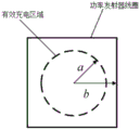
Fig. 2 (a) -2 (b) are diagrams showing the width parameter of the effective charging area and the width parameter of the TX coil with two exemplary embodiments. An effective charging area refers to a charging area of a single TX coil where the inter-coil efficiency should not fall below a desired value (e.g., a user desired or predetermined value) if the center of the RX coil is within the area. The effective charging area is typically evaluated by a width parameter. The width parameter of the effective charging area, denoted a, is defined as the maximum horizontal distance between the center of the TX coil and the center of the RX coil, wherein the inter-coil efficiency should not be lower than the desired value if the center of the RX coil is within the range defined by the width parameter of the effective charging area. The inter-coil efficiency is the efficiency between the TX coil and the RX coil, and is calculated from the ratio of the RX coil output power to the TX coil input power. The efficiency was verified by measurement and simulation. Losses that affect the efficiency between the coils include inter-coil losses and parasitic resistive losses of the TX and RX matching capacitors. The desired inter-coil efficiency (e.g., 90%) may be predetermined/given by the manufacturer or supplier or defined by the customer of the wireless charging system. In this example, the effective charging area is defined as the area where the desired inter-coil efficiency is 90%, where the inter-coil efficiency should not be less than 90% if placed in the center of the RX coil.
In some embodiments, the effective charging area may be defined by the charging efficiency of the wireless charging system. The charging efficiency of the system refers to the ratio of receiver-side output power to transmitter-side input power. A typical threshold for system charging efficiency may be 60%. The charging efficiency of the system may be no less than 60% if the center of the RX coil is located within the active charging region.
As shown in fig. 2 (a) -2 (b), for a circular effective charging area, a is the radius of the area. The width parameter of the physical TX coil, denoted b, is a parameter used to quantify the size of one single TX coil. As shown in fig. 2 (a), for a circular TX coil, b is the radius of the TX coil.
The effective charging area and TX coil are not limited to circular. The width parameters a and b can easily be adapted to different shapes. For example, as shown in fig. 2 (b), if the shape of the TX coil is square, the width parameter b may be expressed as half of the side length of the TX coil. When the required inter-coil efficiency is determined, the effective charging area can be determined by the width parameter b and the inter-coil efficiency.
Fig. 3 (a) - (b) show two exemplary types of mesh cells, triangular mesh cells and rectangular mesh cells. In one embodiment, the triangular mesh cells may be equilateral triangles. In another embodiment, the rectangular grid cells may be square. The circle shown in the grid cell indicates the center of the grid cell. When placing the physical TX coils in step 104, the position of the center of the physical TX coils will correspond to the position of these circles in the grid cell.
Fig. 3 (a) - (b) show the length parameter of the grid cell, denoted w. Which is the length of one side of a grid cell. The length parameter w also corresponds to the distance between two adjacent TX coils. The distance is measured from the center of two adjacent TX coils located on the same layer.
The shape of the grid cell, the range of the length parameter w and the number of layers are correlated and determined by the ratio of a/b. Therefore, the grid cell arrangement pattern is determined by the ratio of a/b. The correlation between a/b, grid cell shape, w and number of layers is shown in table 1 below.
TABLE 1

A larger w means that the distance between two adjacent TX coils is larger, resulting in a lower density of TX coils on one layer. Thus, a larger w may reduce the total number of TX coils in the required charging area.
Fig. 4 shows a floor plan of a single-layer triangular mesh cell placement pattern. The dashed rectangle represents the desired charging area. The desired charging area may be a charging area required or desired by a customer, product designer, or the like. The dashed triangles with circles in their centers represent triangular mesh cells. A mesh cell covers a large portion of the required charging area with its vertices connected to the vertices of its neighboring mesh cells. In one exemplary embodiment, the number of grid cells is the minimum number of grid cells that cover a majority of the required charging area. In the embodiment shown in fig. 4, all grid cells are oriented in the same direction and do not overlap each other on the same layer.
Fig. 5 shows a floor plan of a two-layer triangular mesh cell placement pattern. The dashed rectangle represents the desired charging area. The dashed triangles with circles at the centers represent the first layer triangular mesh cells. Their placement pattern is the same as that shown in fig. 4. The solid line triangles with circles at the centers represent the triangular mesh cells on the second layer. The solid line grid cells cover most of the required charging area on the second layer and their location is determined by the center of three adjacent triangular grid cells on the first layer. As shown in fig. 5, the vertex of each second-level triangle is located at the position of the center circle of the adjacent first-level triangle. In one exemplary embodiment, the number of grid cells on the second level is the number of grid cells that can connect all of the grid cells located at the center of the grid cells on the first level. In another exemplary embodiment, the number of grid cells on the second layer is the minimum number of grid cells covering the majority of the required charging area. Similarly, the second layer of grid cells are oriented in the same direction, are connected to each other by their vertices, and do not overlap each other on the same layer.
Fig. 6 shows a floor plan of a three-level triangular mesh cell placement pattern. The dashed rectangle represents the desired charging area. As shown in fig. 5, the first and second layers of triangular mesh cells are arranged in the same placement pattern. The hatched triangles with circles in their centers represent the third layer of triangular mesh cells. The shaded triangular mesh cells cover most of the required charging area on the third layer and their position is determined by the centre of three adjacent triangular mesh cells on the second layer. As shown in fig. 6, the vertex of each third-level triangle is located at the position of the center circle of the adjacent second-level triangle. In one exemplary embodiment, the number of grid cells on the third level is the number of grid cells that can connect all of the grid cells located at the center of the grid cells on the second level. In another exemplary embodiment, the number of grid cells on the third level is the minimum number of grid cells covering the majority of the required charging area. Similarly, the grid cells of the third layer are oriented in the same direction, are connected to each other by their vertices, and do not overlap each other on the same layer.
FIG. 46 illustrates an exemplary set of floor plan views for a grid cell. The TX coils may be placed based on the layout of the grid cells. One TX coil replaces one grid cell. The center of each grid cell represents the center position of each TX coil. The length parameter w of the grid cell represents the distance between two adjacent TX coils. Top views of exemplary three-layer multi-coil embodiments are shown in fig. 7 (a) - (c). As shown in fig. 7 (a) - (c), the edges of two adjacent TX coils on the same layer can be in contact with each other or placed at a small distance apart. The placement of the grid cells and TX coils shown in fig. 4 and 7 (a) corresponds to scheme 2 in table 1; the placement of the grid cells and TX coils shown in fig. 6 and 7 (c) correspond to scheme 4 in table 1.
Fig. 8 shows a floor plan of a single layer square grid cell placement pattern. The dashed rectangle represents the desired charging area. The solid line squares with circles in their centers represent square grid cells. The grid cells cover a large portion of the required charging area. In one exemplary embodiment, the number of grid cells is the minimum number of grid cells that cover a majority of the required charging area. All grid cells are placed side by side in the same direction and do not overlap each other on the same layer.
Fig. 9 shows a floor plan of a two-layer square grid cell placement pattern. The dashed rectangle represents the desired charging area. Solid line squares with circles in their centers represent the first layer square grid cells. Their placement pattern is the same as that shown in fig. 8. The shaded squares with circles in their centers represent square grid cells on the second layer. The location of the shaded square grid cell is determined by the center of four adjacent square grid cells on the first layer. As shown in fig. 9, the four vertices of each second-layer square are located at the positions of the center circles of four adjacent first-layer squares. In one exemplary embodiment, the number of grid cells on the second layer is the number of grid cells that can connect all centers of grid cells located on the first layer. In another exemplary embodiment, the number of grid cells on the second layer is the minimum number of grid cells covering the majority of the required charging area. Likewise, all grid cells on the second layer are placed side by side in the same direction and do not overlap each other on the same layer.
Fig. 8 and 9 show another set of exemplary floor plan views of grid cells. The TX coils may be placed based on the layout of the grid cells. One TX coil replaces one grid cell. The center of each grid cell represents the center position of each TX coil. The length parameter w of the grid cell represents the distance between two adjacent TX coils. Top views of exemplary dual layer multi-coil embodiments are shown in fig. 10 (a) -10 (b). As shown in fig. 10 (a) -10 (b), the edges of two adjacent TX coils on the same layer can be in contact with each other or placed apart from each other. The placement of the grid cells and TX coils shown in fig. 8 and 10 (a) correspond to scheme 1 in table 1; the placement of the grid cells and TX coils shown in fig. 9 and 10 (b) corresponds to scheme 3 in table 1.
In one embodiment, the ratio of a/b may be no less than Corresponding to scheme 1 in table 1.TX coils can be placed on one layer and the centers of adjacent TX coils can be separated by a length parameter w, wherein>
 As shown in fig. 10 (a), the centers of adjacent four TX coils may form a square.
In another embodiment, the ratio corresponding to scenario 2, a/b in Table 1 may follow TX coils can be placed on one layer and the centers of adjacent TX coils can be separated by a length parameter w, wherein>
 As shown in fig. 7 (a), centers of adjacent three TX coils may form an equilateral triangle.
In another placeIn one embodiment, the ratio corresponding to scheme 3, a/b in Table 1 may be followed TX coils can be placed on two layers and the centers of adjacent TX coils on each layer can be spaced by a length parameter w, where w ≦ 2a. As shown in fig. 10 (b), on each layer, centers of adjacent four TX coils may form a square, and each TX coil on the second layer may be placed in a central area of the square formed by the centers of the adjacent four TX coils on the first layer.
In another embodiment, the ratio corresponding to scenario 4, a/b in Table 1 may be followed The TX coils can be placed on three layers and the centers of adjacent TX coils on each layer can be spaced by a length parameter w, where w ≦ 3a. As shown in fig. 7 (c), on each layer, centers of adjacent three TX coils may form an equilateral triangle, and each TX coil on the third layer may be placed in a central region of the equilateral triangle formed by the centers of the TX coils on the second layer, and each TX coil on the second layer may be placed in a central region of the equilateral triangle formed by the centers of the TX coils on the first layer.
In another embodiment, a wireless charging system may include a charging area and a plurality of TX coils positioned to cover the charging area. Each TX coil may have an effective charging area. The radius of the effective charging area may be denoted as a, and half the width of the TX coil may be denoted as b. The centers of the TX coils may be spaced apart by a distance w. The parameters a, b and w may have the following relationship:
if it is not
If it is not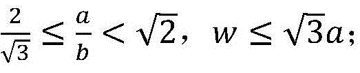
If it is not w is less than or equal to 2a; and
if it is not w≤3a。
w≤3a。
In some embodiments, the TX coil may be placed in one or more layers of the wireless charging system. The centers of adjacent TX coils may be formed in a geometric shape, e.g., an equilateral triangle, a square, etc. The number of layers and shapes is not limited by the scope of the embodiments disclosed herein.
The invention described and claimed herein is not to be limited in scope by the specific preferred embodiments herein disclosed, since these embodiments are intended as illustrations of several aspects of the invention. Indeed, various modifications of the invention in addition to those shown and described herein will become apparent to those skilled in the art from the foregoing description. Such variations are intended to fall within the scope of the appended claims.
Claims (16)


Applications Claiming Priority (3)
| Application Number | Priority Date | Filing Date | Title |
|---|---|---|---|
| US201762460615P | 2017-02-17 | 2017-02-17 | |
| US62/460,615 | 2017-02-17 | ||
| PCT/CN2018/076389 WO2018149381A1 (en) | 2017-02-17 | 2018-02-12 | Multi-coil placement method for power transmitter in wireless charging system |
Publications (2)
| Publication Number | Publication Date |
|---|---|
| CN110313112A CN110313112A (en) | 2019-10-08 |
| CN110313112B true CN110313112B (en) | 2023-04-07 |
Family
ID=63170087
Family Applications (1)
| Application Number | Title | Priority Date | Filing Date |
|---|---|---|---|
| CN201880012350.6A Active CN110313112B (en) | 2017-02-17 | 2018-02-12 | Multi-coil placement method for power transmitter in wireless charging system |
Country Status (3)
| Country | Link |
|---|---|
| US (1) | US10985581B2 (en) |
| CN (1) | CN110313112B (en) |
| WO (1) | WO2018149381A1 (en) |
Families Citing this family (2)
| Publication number | Priority date | Publication date | Assignee | Title |
|---|---|---|---|---|
| US11909226B2 (en) | 2019-05-21 | 2024-02-20 | General Electric Company | Wireless power transmission apparatus with multiple primary coils and adjacent coil muting |
| CN112821571B (en) * | 2020-12-31 | 2023-08-08 | 歌尔股份有限公司 | Charging coil |
Citations (1)
| Publication number | Priority date | Publication date | Assignee | Title |
|---|---|---|---|---|
| CN106356917A (en) * | 2016-08-30 | 2017-01-25 | 于士博 | Wireless charging transmitting device |
Family Cites Families (10)
| Publication number | Priority date | Publication date | Assignee | Title |
|---|---|---|---|---|
| US8169185B2 (en) * | 2006-01-31 | 2012-05-01 | Mojo Mobility, Inc. | System and method for inductive charging of portable devices |
| KR20140039269A (en) * | 2011-06-10 | 2014-04-01 | 액세스 비지니스 그룹 인터내셔날 엘엘씨 | System and method for detecting, characterizing, and tracking an inductive power receiver |
| CN104380567A (en) * | 2012-02-16 | 2015-02-25 | 奥克兰联合服务有限公司 | Multi-Coil Flux Liners |
| WO2013153736A1 (en) * | 2012-04-10 | 2013-10-17 | パナソニック株式会社 | Wireless power transmitting apparatus, power transmitting apparatus, and power receiving apparatus |
| US10014104B2 (en) * | 2012-11-02 | 2018-07-03 | Qualcomm Incorporated | Coil arrangements in wireless power transfer systems for low electromagnetic emissions |
| CN103280848B (en) | 2013-04-28 | 2015-07-15 | 深圳市中远航科技有限公司 | Wireless charging device |
| CN103532255A (en) | 2013-10-31 | 2014-01-22 | 武汉大学 | Wireless magnetic-resonance charging device based on array coils |
| CN203632526U (en) | 2013-11-25 | 2014-06-04 | 北京突破电气有限公司 | Power converter with intelligent wireless charging function |
| US10374459B2 (en) | 2015-03-29 | 2019-08-06 | Chargedge, Inc. | Wireless power transfer using multiple coil arrays |
| JP6512600B2 (en) * | 2015-04-13 | 2019-05-15 | 一般財団法人電力中央研究所 | Contactless power transmission circuit and contactless power supply system |
-
2018
- 2018-02-08 US US15/892,043 patent/US10985581B2/en active Active
- 2018-02-12 WO PCT/CN2018/076389 patent/WO2018149381A1/en not_active Ceased
- 2018-02-12 CN CN201880012350.6A patent/CN110313112B/en active Active
Patent Citations (1)
| Publication number | Priority date | Publication date | Assignee | Title |
|---|---|---|---|---|
| CN106356917A (en) * | 2016-08-30 | 2017-01-25 | 于士博 | Wireless charging transmitting device |
Also Published As
| Publication number | Publication date |
|---|---|
| CN110313112A (en) | 2019-10-08 |
| US20190052103A1 (en) | 2019-02-14 |
| WO2018149381A1 (en) | 2018-08-23 |
| US10985581B2 (en) | 2021-04-20 |
Similar Documents
| Publication | Publication Date | Title |
|---|---|---|
| US9984815B2 (en) | Wireless power transfer apparatus and power supplies including overlapping magnetic cores | |
| TWI425533B (en) | Transformer | |
| JP6772140B2 (en) | Transmitter charging station and optimization method | |
| CN110313112B (en) | Multi-coil placement method for power transmitter in wireless charging system | |
| CN111755225A (en) | Inductive device | |
| JP2013533607A (en) | Improved receiver coil | |
| EP3218988A1 (en) | Inductive power transmitter | |
| JP2017536796A (en) | Tile wireless charging coil means for extended active area | |
| CN103890875A (en) | Arrangement and method for contactless energy transmission with a coupling-minimized matrix of planar transmission coils | |
| CN109166708A (en) | A kind of change turn-to-turn is away from planar spiral winding | |
| CN105023739A (en) | Integrated transformer | |
| CN104779715B (en) | Automatic positioning method based on wireless energy transfer system under many power coil | |
| CN214755754U (en) | Combined foreign matter detection coil without detection blind area | |
| KR20200055426A (en) | Printed Circuit Board Coil | |
| CN113391360A (en) | Combined foreign matter detection coil without detection blind area and detection method thereof | |
| JP2006086460A (en) | Coupling coil | |
| CN110676028B (en) | Transformer device | |
| US20180191198A1 (en) | Wireless power transmitter | |
| US20190254126A1 (en) | Induction heating arrangement | |
| CN106464032B (en) | Charging device with small-ring transmission coil for wirelessly charging target equipment | |
| CN206758635U (en) | Antenna assembly and the electronic equipment for possessing antenna assembly | |
| AU2016257612B2 (en) | Induction coil for an induction heating appliance | |
| CN115964876B (en) | A method for constructing a dual-load wireless power transfer rectangular coil | |
| AU2016427625B2 (en) | Induction coil for an induction heating appliance | |
| KR101102340B1 (en) | 3D inductor |
Legal Events
| Date | Code | Title | Description |
|---|---|---|---|
| PB01 | Publication | ||
| PB01 | Publication | ||
| SE01 | Entry into force of request for substantive examination | ||
| SE01 | Entry into force of request for substantive examination | ||
| GR01 | Patent grant | ||
| GR01 | Patent grant |