CN110313048B - Reduced coulomb interaction in a multi-beam column - Google Patents
Reduced coulomb interaction in a multi-beam column Download PDFInfo
- Publication number
- CN110313048B CN110313048B CN201880009523.9A CN201880009523A CN110313048B CN 110313048 B CN110313048 B CN 110313048B CN 201880009523 A CN201880009523 A CN 201880009523A CN 110313048 B CN110313048 B CN 110313048B
- Authority
- CN
- China
- Prior art keywords
- electron beam
- lens array
- limiting aperture
- electron
- source
- Prior art date
- Legal status (The legal status is an assumption and is not a legal conclusion. Google has not performed a legal analysis and makes no representation as to the accuracy of the status listed.)
- Active
Links
Images


Classifications
-
- H—ELECTRICITY
- H01—ELECTRIC ELEMENTS
- H01J—ELECTRIC DISCHARGE TUBES OR DISCHARGE LAMPS
- H01J37/00—Discharge tubes with provision for introducing objects or material to be exposed to the discharge, e.g. for the purpose of examination or processing thereof
- H01J37/02—Details
- H01J37/04—Arrangements of electrodes and associated parts for generating or controlling the discharge, e.g. electron-optical arrangement, ion-optical arrangement
- H01J37/045—Beam blanking or chopping, i.e. arrangements for momentarily interrupting exposure to the discharge
-
- H—ELECTRICITY
- H01—ELECTRIC ELEMENTS
- H01J—ELECTRIC DISCHARGE TUBES OR DISCHARGE LAMPS
- H01J37/00—Discharge tubes with provision for introducing objects or material to be exposed to the discharge, e.g. for the purpose of examination or processing thereof
- H01J37/02—Details
- H01J37/04—Arrangements of electrodes and associated parts for generating or controlling the discharge, e.g. electron-optical arrangement, ion-optical arrangement
- H01J37/09—Diaphragms; Shields associated with electron or ion-optical arrangements; Compensation of disturbing fields
-
- H—ELECTRICITY
- H01—ELECTRIC ELEMENTS
- H01J—ELECTRIC DISCHARGE TUBES OR DISCHARGE LAMPS
- H01J37/00—Discharge tubes with provision for introducing objects or material to be exposed to the discharge, e.g. for the purpose of examination or processing thereof
- H01J37/02—Details
- H01J37/04—Arrangements of electrodes and associated parts for generating or controlling the discharge, e.g. electron-optical arrangement, ion-optical arrangement
- H01J37/10—Lenses
-
- H—ELECTRICITY
- H01—ELECTRIC ELEMENTS
- H01J—ELECTRIC DISCHARGE TUBES OR DISCHARGE LAMPS
- H01J37/00—Discharge tubes with provision for introducing objects or material to be exposed to the discharge, e.g. for the purpose of examination or processing thereof
- H01J37/30—Electron-beam or ion-beam tubes for localised treatment of objects
- H01J37/317—Electron-beam or ion-beam tubes for localised treatment of objects for changing properties of the objects or for applying thin layers thereon, e.g. for ion implantation
- H01J37/3174—Particle-beam lithography, e.g. electron beam lithography
- H01J37/3177—Multi-beam, e.g. fly's eye, comb probe
-
- H—ELECTRICITY
- H01—ELECTRIC ELEMENTS
- H01J—ELECTRIC DISCHARGE TUBES OR DISCHARGE LAMPS
- H01J2237/00—Discharge tubes exposing object to beam, e.g. for analysis treatment, etching, imaging
- H01J2237/04—Means for controlling the discharge
- H01J2237/043—Beam blanking
- H01J2237/0435—Multi-aperture
-
- H—ELECTRICITY
- H01—ELECTRIC ELEMENTS
- H01J—ELECTRIC DISCHARGE TUBES OR DISCHARGE LAMPS
- H01J2237/00—Discharge tubes exposing object to beam, e.g. for analysis treatment, etching, imaging
- H01J2237/04—Means for controlling the discharge
- H01J2237/045—Diaphragms
- H01J2237/0451—Diaphragms with fixed aperture
- H01J2237/0453—Diaphragms with fixed aperture multiple apertures
-
- H—ELECTRICITY
- H01—ELECTRIC ELEMENTS
- H01J—ELECTRIC DISCHARGE TUBES OR DISCHARGE LAMPS
- H01J2237/00—Discharge tubes exposing object to beam, e.g. for analysis treatment, etching, imaging
- H01J2237/06—Sources
- H01J2237/061—Construction
Abstract
The performance of a multi-electron beam system can be improved by reducing coulombic effects in the illumination path of the multi-beam inspection system. A beam limiting aperture having a plurality of apertures may be located between the electron beam source and the multi-lens array, e.g. in a field-free region. The beam limiting aperture is configured to reduce coulomb interaction between the electron beam source and the multi-lens array. An electron beam system having the beam limiting aperture may be used in a scanning electron microscope.
Description
Technical Field
The present invention relates to electron beam systems.
Background
Previous electron beam inspection systems generated an electron beam by a schottky thermal field electron emitter. Surrounding the emitter is a suppressor electrode that suppresses unwanted hot electrons from the emitter's shank from entering the primary beam. The voltage on the extractor electrode determines the electric field at the apex of the tip. The field at the tip determines the amount of current that can be drawn from the tip. A second electrode or anode after the extractor is typically used to accelerate the beam to the desired energy. The current distribution from the emitter extends to a few degrees. In electron beam inspection systems, a small source acceptance angle of less than 1 degree may require high resolution. In Scanning Electron Microscopy (SEM), a jet aperture is typically used to block unused electrons. A second aperture located further below the cylinder may serve as a pupil aperture, which sets the Numerical Aperture (NA) of the objective lens. This design still has the problem of coulomb effect.
Accordingly, there is a need for an improved electron beam system.
Disclosure of Invention
In a first embodiment, an electron beam system is provided. The electron beam system includes: an electron beam source; a multi-lens array; and a beam limiting aperture defining a plurality of apertures. The beam limiting aperture is disposed between the electron beam source and the multi-lens array. The beam limiting aperture is configured to reduce coulomb interaction between the electron beam source and the multi-lens array. The beam limiting aperture may be made of silicon, metal or metal alloy. The electron beam source may include an emitter, suppressor, and extractor.
The beam limiting aperture may be disposed at a location between the electron beam source and the multi-lens array having a field of less than 1V/mm. For example, the location between the electron beam source and the multi-lens array may be field-free.
The beam limiting aperture may define at least 6 of the holes. The beam limiting aperture can define the apertures to each have a diameter from 1 μm to 100 μm. For example, the diameter of each of the pores may be 50 μm. The beam limiting aperture can define the aperture to have a pitch from 2 μm to 100 μm. For example, the pitch may be 100 μm. The beam limiting aperture may define the apertures as each being circular. The apertures may be disposed in the beam limiting aperture in a polygonal arrangement.
The scanning electron microscope may include the electron beam system of any of the design variations or examples of the first embodiment.
A method is provided in a second embodiment. The method comprises the following steps: generating an electron beam; extracting the electron beam; directing the electron beam through a beam limiting aperture defining a plurality of apertures; and directing the electron beam through a multi-lens array located downstream of the beam limiting aperture relative to a projection direction of the electron beam. The beam limiting aperture is configured to reduce coulomb interaction between the electron beam source and the multi-lens array.
The electron beam may be located in a region having a field of less than 1V/mm when the electron beam passes through the beam limiting aperture. For example, the region may be a field-free region.
The electron beam passing through the multi-lens array may be focused to a diameter of 50 nm.
A system is provided in a third embodiment. The system comprises: an electron beam source configured to generate an electron beam; a multi-lens array located upstream of the wafer; a beam limiting aperture defining a plurality of apertures; and a detector configured to detect electrons from the electron beam returning from a surface of the wafer. The beam limiting aperture is disposed between the electron beam source and the multi-lens array. The beam limiting aperture is configured to reduce coulomb interaction between the electron beam source and the multi-lens array.
The beam limiting aperture may be disposed at a location between the electron beam source and the multi-lens array having a field of less than 1V/mm. For example, the location between the electron beam source and the multi-lens array may be field-free.
Drawings
For a fuller understanding of the nature and objects of the present invention, reference should be made to the following detailed description taken together with the accompanying figures in which:
FIG. 1 is a schematic view of an embodiment of an electron beam system according to the invention;
FIG. 2 is a first electron beam histogram;
FIG. 3 is a second electron beam histogram;
FIG. 4 is a third electron beam histogram;
FIG. 5 is a fourth electron beam histogram;
FIG. 6 is a fifth electron beam histogram;
FIG. 7 is an embodiment of a system according to the present invention; and is
Fig. 8 is a flow chart of a method according to the invention.
Detailed Description
Although claimed subject matter will be described with respect to particular embodiments, other embodiments are within the scope of the disclosure, including embodiments that do not provide all of the benefits and features set forth herein. Various structural, logical, procedural, and electrical changes may be made without departing from the scope of the present invention. The scope of the invention is, therefore, defined only by reference to the appended claims.
Embodiments disclosed herein improve the performance of multi-electron beam systems by reducing coulombic effects in the illumination path of the multi-beam inspection system. A Beam Limiting Aperture (BLA) may be used to block unused electrons from the successive downstream, e.g., to prevent charging and/or gas ionization. BLAs can help reduce coulomb effects. As electrons travel through the electron-optical column, the electrons interact with each other as described by coulomb's law, since the electrons are charged particles. The cumulative effect of the number of electrons in the electron column and the length of time the electrons spend in the electron column determines the magnitude of the coulomb effect. Introducing the BLA into the beam path near the electron source removes electrons, so there are fewer electrons in the electron-optical column in most of the electron path. The magnitude of the coulomb effect can be reduced because there are fewer electrons.
Fig. 1 is a schematic diagram of an embodiment of an electron beam system 100. The electron beam system 100 includes an electron beam source 101, a Beam Limiting Aperture (BLA)103, and a multi-lens array (MLA) 104. The electron beam source 101 may include an emitter 109, a suppressor 110, and an extractor 102.
The BLA 103 may be positioned proximate the electron beam source 101 to reduce space charge effects. In one example, in the field-free region, the BLA 103 is as close as possible to the extractor 102. The BLA 103 may be slightly lower than the anode 106 at ground potential.
The BLA 103 may be fabricated from silicon, a metal alloy, or another material that provides acceptable power and/or heat dissipation. The material of the BLA 103 may resist melting or distortion caused by heat. The BLA 103 may be connected to an anode 106. The BLA 103 may have a thickness from 2 to 25 μm, but other dimensions are possible.
The BLAs 103 may be referred to as "pepper pot" BLAs. The BLA 103 in fig. 1 defines a plurality of holes 105 through the BLA 103. BLA 103 may include from 1 well 105 to 2,000 or 3,000 wells 103, including all ranges and values therebetween. In one example, the BLA 103 defines 6 or 7 holes 105. More or fewer apertures 105 may be included in the BLA 103.
Each hole 105 may have a diameter from 1 μm to 100 μm, including all values to 0.5 μm and ranges there between. In one example, each hole 105 has a diameter of 50 μm. In another example, each hole 105 has a diameter from 1 μm to 10 μm, including all values to 0.5 μm and ranges therebetween. The aperture 105 may be slightly oversized relative to the size of the electron beam such that the illumination overfills the pupil aperture of the MLA 104. The BLA 103 may also act as a shield to block part of the electron beam.
The holes 105 may be positioned in the BLA 103 with a pitch from 2 μm to 100 μm, including all values to 0.5 μm and ranges there between. In one example, the pitch of the holes 105 in the BLA 103 is 100 μm.
The inset of fig. 1 (which is not drawn to scale with the rest of fig. 1) is an example of a front view of the BLA 103 taken along line a-a. Each of the holes 105 may be circular, polygonal, or other shape. The 6 holes 105 are arranged in a polygonal pattern (shown with dashed lines).
In another example, the BLAs 103 define 7 holes 105 in a polygonal arrangement. In yet another example, BLA 103 defines approximately 1,000 holes 105. In the example of a BLA 103 for assay, the BLA 103 includes 331 holes 105.
It may be beneficial to arrange the holes 105 in the BLA 103 in a polygonal pattern, since the holes 105 will be arranged in a near circular manner. The electron optics for the electron beam inspection system are rotationally symmetric. To optimize the area in the macro electron lens, a pattern close to a circle may be desired.
As the electron beam 107 generated by the electron beam source 101 passes through the aperture 105 of the BLA 103, the electron beam 107 is transformed by the BLA 103 into a plurality of beamlets 108. Each aperture 105 produces a beamlet 108. Each beamlet 108 may exit the BLA 103 at a diameter of approximately 50 nm. The design of the electron beam system 100 may provide a plurality of small beamlets 108 that are dispersed from one another. The remainder of the electron beam 107 is blocked by the BLA 103.
The MLA104 includes a 2D lens array. An individual lens in the MLA104 may have a plurality of apertures along the optical axis or third axis of that particular lens. In one example, there is a one-to-one mapping of the aperture in the lens of the MLA104 to the aperture 105 in the BLA 103.
By flood illuminating the MLA104, a multi-beam system is created, which may be electrostatic. The electrostatic lens is formed by placing an electric field across the aperture of the MLA 104. Each individual lens forms an image of the electron beam source 101 at the virtual source plane, which is then reduced onto the wafer. To illuminate the MLA104, a large illumination angle from the source may be required. For example, this illumination angle may be up to two degrees, although other values are possible.
The BLA 103 is positioned between the electron beam source 101 and the MLA 104. The BLA 103 may be located between the electron beam source 101 and the MLA104 in an area or location of less than 1V/mm or no field, meaning that there may be minimal or even no lens effect of the aperture 105. Thus, the BLA 103 may not focus the beamlet 108. No field may mean 0V/mm, but may be other values close to 0V/mm under which no lensing effect occurs. Positioning the BLA 103 between the electron beam source 101 and the MLA104 may reduce coulomb interaction in this region. As such, the BLA 103 may not act as an optical component, which reduces tolerance requirements. In an example, the electron beam current delivered to the wafer may be doubled, tripled, or quadrupled at a resolution from about 3nm to 10 nm.
Electron interactions and coulombic interactions can cause problems. For example, these interactions may increase blur caused by chromatic aberration or dispersion. The lateral blur may not be corrected. The BLAs 103 are configured to reduce coulomb interaction between the electron beam source 101 and the MLA 104. The separation of beamlets 108 may further improve performance by reducing crosstalk.
In one example, emitter 109 is at-VEOperating with extractor 102 at-VextOperate with suppressor 110 at-VS(e.g., -V)E1000V) and the anode at 0V. A voltage may also be applied to the MLA 104. For example, -VEIs from 6000V to 30,000V, and-Vextis-VEPlus from 3000V to 7000V.
Downstream of the MLA104 with respect to the direction of the electron beam or beamlet 108 is a magnetic lens 111 having at least one coil 113 and a pole piece 112. Element 114 adjusts the trajectory, focus, and/or size of beamlet 108.
For example, the electron beam system 100 may be used in an SEM or other device.
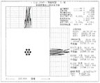
Fig. 2 to 6 are electron beam histograms according to Monte Carlo (Monte Carlo) simulations. FIG. 3 shows a 250 μm electron beam upstream of the BLA. Fig. 4 shows the electron beam downstream of the BLA. FIG. 5 shows an electron beam upstream of the MLA. FIG. 6 shows an electron beam downstream of the MLA. Fig. 7 shows an intermediate image of the electron beam. As disclosed herein, using BLAs reduces coulomb blur as shown by the simulations in fig. 3-7. The central beam blur is reduced from D2080-31 nm compared to 49nm without BLA. The total current was reduced from 16.1nA without BLA to 6.3nA with BLA. As seen in these simulations, the BLA may provide improved performance that is twice as good as a system without the BLA.
Embodiments described herein may include or be executable in a system, such as system 200 of fig. 7. The system 200 includes an output acquisition subsystem including at least an energy source and a detector. The output acquisition subsystem may be an electron beam-based output acquisition subsystem. For example, in one embodiment, the energy directed to the wafer 204 includes electrons and the energy detected from the wafer 204 includes electrons. In this manner, the energy source may be an electron beam source 202, which may include or be coupled with an electron beam system as disclosed herein. In one such embodiment shown in fig. 7, the output acquisition subsystem includes an electron optical column 201 coupled to a computer subsystem 207.
As also shown in fig. 7, the electron optical column 201 includes an electron beam source 202 configured to generate electrons focused through one or more elements 203 to a wafer 204. The electron beam source 202 may include an emitter and the one or more elements 203 may include, for example, a gun lens, an anode, a BLA, an MLA, a gate valve, a beam current selection aperture, an objective lens, and/or a scanning subsystem. The electron column 201 may comprise any other suitable element known in the art. Although only one electron beam source 202 is illustrated, the system 200 may include multiple electron beam sources 202.
Electrons (e.g., secondary electrons) returning from the wafer 204 may be focused by one or more elements 205 to a detector 206. One or more elements 205 may include, for example, a scanning subsystem, which may be the same scanning subsystem included in element 203. The electron column 201 may comprise any other suitable element known in the art.
Although the electron column 201 is shown in fig. 7 as being configured such that electrons are directed to the wafer 204 at an oblique angle of incidence and scattered from the wafer at another oblique angle, it is understood that the electron beam may be directed to and scattered from the wafer at any suitable angle. In addition, the electron beam-based output acquisition subsystem may be configured to generate images of wafer 204 using multiple modes (e.g., at different illumination angles, collection angles, etc.). The multiple modes of the electron beam based output acquisition subsystem may differ in any image generation parameter of the output acquisition subsystem.
The computer subsystem 207 may be in electronic communication with the detector 206. The detector 206 may detect electrons returning from the surface of the wafer 204 thereby forming an electron beam image of the wafer 204. The electron beam image may comprise any suitable electron beam image. The computer subsystem 207 may be configured to perform other functions or additional steps using the output of the detector 206 and/or the electron beam image.
It should be noted that fig. 7 is provided herein to generally illustrate the configuration of an electron beam based output acquisition subsystem. The electron beam-based output acquisition subsystem configurations described herein may be altered to optimize the performance of the output acquisition subsystem, as is typically performed when designing commercial output acquisition systems. Additionally, the systems described herein may be implemented using existing systems (e.g., by adding the functionality described herein to an existing system). For some such systems, the methods described herein may be provided as optional functionality of the system (e.g., in addition to other functionality of the system).
In one embodiment, system 200 is a verification system. For example, the electron beam output acquisition subsystem described herein may be configured as an inspection system. In another embodiment, system 200 is a defect review system. For example, the electron beam output acquisition subsystem described herein may be configured as a defect review system. In yet another embodiment, the system 200 is a metrology system. For example, the electron beam output acquisition subsystem described herein may be configured as a metrology system. In particular, one or more parameters of the embodiment of the system 200 described herein and shown in fig. 7 may be modified to provide different imaging capabilities depending on the application in which the parameters will be used. In one such example, the system 200 shown in fig. 7 may be configured to have higher resolution if it is to be used for defect review or metrology, rather than for inspection. In other words, the embodiment of the system 200 shown in fig. 7 describes some general and various configurations of the system 200, which may be tailored in several ways to produce output acquisition subsystems having different imaging capabilities more or less suited for different applications.
In particular, the embodiments described herein may be installed on a computer node or cluster of computers that is a component of or coupled to an output acquisition subsystem, such as an e-beam inspector or defect review tool, a mask inspector, a virtual inspector, or other device. In this manner, the embodiments described herein can generate output that can be used for a variety of applications including, but not limited to, wafer inspection, mask inspection, e-beam inspection and review, metrology, or other applications. The characteristics of the system 200 shown in fig. 7 may be modified as described above based on the sample that will produce the output.
Fig. 8 is a flow chart of a method 300. An electron beam is generated 301, extracted 302, directed through a BLA 303 and directed through an MLA 304 located downstream of the BLA with respect to the projection direction of the electron beam. The BLA defines a plurality of pores. The BLA is configured to reduce coulomb interaction between the electron beam source and the multi-lens array. The electron beam may be located in an area less than 1V/mm when the electron beam passes through the BLA or a field-free area. The electron beam passing through the MLA can be focused to a diameter of, for example, 50 nm.
Each of the steps of the method may be performed as described herein. The method may also include any other steps that may be performed by the controller and/or computer subsystem or system described herein. The steps may be performed by one or more computer systems, which may be configured in accordance with any of the embodiments described herein. Additionally, the methods described above may be performed by any of the system embodiments described herein.
Although the invention has been described with respect to one or more particular embodiments, it is to be understood that other embodiments of the invention may be made without departing from the scope of the invention. Accordingly, the present invention is considered to be limited only by the following claims and the reasonable interpretation thereof.
Claims (20)
1. An electron beam system, comprising:
an electron beam source;
a multi-lens array;
a beam limiting aperture defining a plurality of apertures, wherein the beam limiting aperture is disposed between the electron beam source and the multi-lens array, and wherein the beam limiting aperture is configured to reduce beam blurring between the electron beam source and the multi-lens array;
an element on an opposite side of the multi-lens array from the electron beam source, wherein the element is configured to adjust a focal length of beamlets from the multi-lens array; and
a magnetic lens disposed between the multi-lens array and the element.
2. The electron beam system of claim 1, wherein the beam limiting aperture is disposed at a location between the electron beam source and the multi-lens array having a field of less than 1V/mm.
3. The electron beam system of claim 2, wherein the location between the electron beam source and the multi-lens array is field-free.
4. The electron beam system of claim 1, wherein the beam limiting aperture defines at least 6 of the apertures.
5. The electron beam system of claim 1, wherein the electron beam source includes an emitter, a suppressor, and an extractor.
6. The electron beam system of claim 1, wherein the beam limiting aperture defines the apertures to each have a diameter from 1 μ ι η to 100 μ ι η.
7. The electron beam system of claim 6, wherein the diameter of each of the holes is 50 μ ι η.
8. The electron beam system of claim 1, wherein the beam limiting aperture defines the aperture to have a pitch from 2 μ ι η to 100 μ ι η.
9. The electron beam system of claim 8, wherein the pitch is 100 μ ι η.
10. The electron beam system of claim 1, wherein the beam limiting aperture is fabricated from silicon, a metal, or a metal alloy.
11. The electron beam system of claim 1, wherein the beam limiting aperture defines the apertures to be each circular.
12. The electron beam system of claim 1, wherein the apertures are disposed in the beam limiting aperture in a polygonal arrangement.
13. A scanning electron microscope comprising the electron beam system of claim 1.
14. A method of operating an electron beam, the method comprising:
generating the electron beam;
extracting the electron beam;
directing the electron beam through a beam limiting aperture defining a plurality of apertures;
directing the electron beam through a multi-lens array located downstream of the beam limiting aperture relative to a projection direction of the electron beam, wherein the beam limiting aperture is configured to reduce beam blur between an electron beam source and the multi-lens array;
directing the electron beam through a magnetic lens located downstream of the multi-lens array with respect to the projection direction of the electron beam; and
directing the electron beam through an element located downstream of the magnetic lens relative to the projection direction of the electron beam, wherein the element is configured to adjust a focal length of a beamlet from the magnetic lens.
15. The method of claim 14, wherein the electron beam is located in a region having a field of less than 1V/mm as the electron beam passes through the beam limiting aperture.
16. The method of claim 15, wherein the region is a field-free region.
17. The method of claim 14, wherein the electron beams passing through the multi-lens array are focused to a diameter of 50 nm.
18. An electron beam system, comprising:
an electron beam source configured to generate an electron beam;
a multi-lens array located upstream of the wafer;
a beam limiting aperture defining a plurality of apertures, wherein the beam limiting aperture is disposed between the electron beam source and the multi-lens array, and wherein the beam limiting aperture is configured to reduce beam blurring between the electron beam source and the multi-lens array;
an element on an opposite side of the multi-lens array from the electron beam source, wherein the element is configured to adjust a focal length of beamlets from the multi-lens array;
a magnetic lens disposed between the multi-lens array and the element; and
a detector configured to detect electrons from the electron beam returning from a surface of the wafer.
19. The system of claim 18, wherein the beam limiting aperture is disposed at a location between the electron beam source and the multi-lens array having a field of less than 1V/mm.
20. The system of claim 19, wherein the location between the electron beam source and the multi-lens array is field-free.
Applications Claiming Priority (3)
| Application Number | Priority Date | Filing Date | Title |
|---|---|---|---|
| US15/587,720 US10242839B2 (en) | 2017-05-05 | 2017-05-05 | Reduced Coulomb interactions in a multi-beam column |
| US15/587,720 | 2017-05-05 | ||
| PCT/US2018/013425 WO2018203936A1 (en) | 2017-05-05 | 2018-01-12 | Reduced coulomb interactions in a multi-beam column |
Publications (2)
| Publication Number | Publication Date |
|---|---|
| CN110313048A CN110313048A (en) | 2019-10-08 |
| CN110313048B true CN110313048B (en) | 2021-03-12 |
Family
ID=64014281
Family Applications (1)
| Application Number | Title | Priority Date | Filing Date |
|---|---|---|---|
| CN201880009523.9A Active CN110313048B (en) | 2017-05-05 | 2018-01-12 | Reduced coulomb interaction in a multi-beam column |
Country Status (7)
| Country | Link |
|---|---|
| US (1) | US10242839B2 (en) |
| EP (1) | EP3549154A4 (en) |
| JP (2) | JP2020518990A (en) |
| KR (1) | KR102352097B1 (en) |
| CN (1) | CN110313048B (en) |
| IL (1) | IL267815B (en) |
| WO (1) | WO2018203936A1 (en) |
Families Citing this family (4)
| Publication number | Priority date | Publication date | Assignee | Title |
|---|---|---|---|---|
| US11615938B2 (en) * | 2019-12-20 | 2023-03-28 | Nuflare Technology, Inc. | High-resolution multiple beam source |
| EP4088301A1 (en) | 2020-01-06 | 2022-11-16 | ASML Netherlands B.V. | Charged particle assessment tool, inspection method |
| US11699564B2 (en) * | 2020-10-23 | 2023-07-11 | Nuflare Technology, Inc. | Schottky thermal field emitter with integrated beam splitter |
| US11651934B2 (en) | 2021-09-30 | 2023-05-16 | Kla Corporation | Systems and methods of creating multiple electron beams |
Citations (3)
| Publication number | Priority date | Publication date | Assignee | Title |
|---|---|---|---|---|
| CN101019203A (en) * | 2004-05-17 | 2007-08-15 | 迈普尔平版印刷Ip有限公司 | Charged particle beam exposure system |
| CN101414533A (en) * | 2002-10-30 | 2009-04-22 | 迈普尔平版印刷Ip有限公司 | Electron beam exposure system |
| CN101496129A (en) * | 2006-07-25 | 2009-07-29 | 迈普尔平版印刷Ip有限公司 | A multiple beam charged particle optical system |
Family Cites Families (25)
| Publication number | Priority date | Publication date | Assignee | Title |
|---|---|---|---|---|
| US4419182A (en) * | 1981-02-27 | 1983-12-06 | Veeco Instruments Inc. | Method of fabricating screen lens array plates |
| JP4647820B2 (en) * | 2001-04-23 | 2011-03-09 | キヤノン株式会社 | Charged particle beam drawing apparatus and device manufacturing method |
| JP2003077814A (en) * | 2001-09-05 | 2003-03-14 | Nikon Corp | Method of measuring imaging performance of charged particle beam exposure device, method thereof and charged particle beam exposure device |
| US6768125B2 (en) * | 2002-01-17 | 2004-07-27 | Ims Nanofabrication, Gmbh | Maskless particle-beam system for exposing a pattern on a substrate |
| JP4459568B2 (en) * | 2003-08-06 | 2010-04-28 | キヤノン株式会社 | Multi charged beam lens and charged beam exposure apparatus using the same |
| GB2408143B (en) * | 2003-10-20 | 2006-11-15 | Ims Nanofabrication Gmbh | Charged-particle multi-beam exposure apparatus |
| US7176459B2 (en) | 2003-12-25 | 2007-02-13 | Ebara Corporation | Electron beam apparatus |
| EP2270834B9 (en) * | 2005-09-06 | 2013-07-10 | Carl Zeiss SMT GmbH | Particle-optical component |
| US8134135B2 (en) * | 2006-07-25 | 2012-03-13 | Mapper Lithography Ip B.V. | Multiple beam charged particle optical system |
| KR101118692B1 (en) * | 2006-10-11 | 2012-03-12 | 전자빔기술센터 주식회사 | An electron column using a magnetic lens layer |
| JP5103033B2 (en) * | 2007-03-02 | 2012-12-19 | 株式会社日立ハイテクノロジーズ | Charged particle beam application equipment |
| US7821187B1 (en) * | 2007-09-07 | 2010-10-26 | Kla-Tencor Corporation | Immersion gun equipped electron beam column |
| US7960697B2 (en) | 2008-10-23 | 2011-06-14 | Hermes-Microvision, Inc. | Electron beam apparatus |
| JP2011059057A (en) * | 2009-09-14 | 2011-03-24 | Fujitsu Ltd | Electron spin analyzer and surface observation device |
| US8294125B2 (en) * | 2009-11-18 | 2012-10-23 | Kla-Tencor Corporation | High-sensitivity and high-throughput electron beam inspection column enabled by adjustable beam-limiting aperture |
| US9184024B2 (en) | 2010-02-05 | 2015-11-10 | Hermes-Microvision, Inc. | Selectable coulomb aperture in E-beam system |
| TWI593961B (en) * | 2010-12-15 | 2017-08-01 | 日立全球先端科技股份有限公司 | Charged particle line application device, and irradiation method |
| US8362425B2 (en) | 2011-03-23 | 2013-01-29 | Kla-Tencor Corporation | Multiple-beam system for high-speed electron-beam inspection |
| KR20120128105A (en) * | 2011-05-16 | 2012-11-26 | 캐논 가부시끼가이샤 | Drawing apparatus and method of manufacturing article |
| US8618480B2 (en) * | 2012-03-23 | 2013-12-31 | Hermes Microvision Inc. | Charged particle beam apparatus |
| EP2879155B1 (en) * | 2013-12-02 | 2018-04-25 | ICT Integrated Circuit Testing Gesellschaft für Halbleiterprüftechnik mbH | Multi-beam system for high throughput EBI |
| JP2016197503A (en) * | 2015-04-02 | 2016-11-24 | 株式会社ニューフレアテクノロジー | Electron beam device |
| US9607805B2 (en) * | 2015-05-12 | 2017-03-28 | Hermes Microvision Inc. | Apparatus of plural charged-particle beams |
| US9922799B2 (en) * | 2015-07-21 | 2018-03-20 | Hermes Microvision, Inc. | Apparatus of plural charged-particle beams |
| KR102007497B1 (en) | 2015-07-22 | 2019-08-05 | 에이에스엠엘 네델란즈 비.브이. | Apparatus using a plurality of charged particle beams |
-
2017
- 2017-05-05 US US15/587,720 patent/US10242839B2/en active Active
-
2018
- 2018-01-12 CN CN201880009523.9A patent/CN110313048B/en active Active
- 2018-01-12 WO PCT/US2018/013425 patent/WO2018203936A1/en unknown
- 2018-01-12 IL IL267815A patent/IL267815B/en unknown
- 2018-01-12 EP EP18793779.2A patent/EP3549154A4/en active Pending
- 2018-01-12 KR KR1020197036059A patent/KR102352097B1/en active IP Right Grant
- 2018-01-12 JP JP2019560662A patent/JP2020518990A/en active Pending
-
2022
- 2022-02-03 JP JP2022015515A patent/JP7329637B2/en active Active
Patent Citations (3)
| Publication number | Priority date | Publication date | Assignee | Title |
|---|---|---|---|---|
| CN101414533A (en) * | 2002-10-30 | 2009-04-22 | 迈普尔平版印刷Ip有限公司 | Electron beam exposure system |
| CN101019203A (en) * | 2004-05-17 | 2007-08-15 | 迈普尔平版印刷Ip有限公司 | Charged particle beam exposure system |
| CN101496129A (en) * | 2006-07-25 | 2009-07-29 | 迈普尔平版印刷Ip有限公司 | A multiple beam charged particle optical system |
Also Published As
| Publication number | Publication date |
|---|---|
| CN110313048A (en) | 2019-10-08 |
| IL267815B (en) | 2022-08-01 |
| WO2018203936A1 (en) | 2018-11-08 |
| JP2020518990A (en) | 2020-06-25 |
| KR102352097B1 (en) | 2022-01-14 |
| IL267815A (en) | 2019-09-26 |
| EP3549154A1 (en) | 2019-10-09 |
| KR20190138898A (en) | 2019-12-16 |
| EP3549154A4 (en) | 2020-07-22 |
| JP7329637B2 (en) | 2023-08-18 |
| US10242839B2 (en) | 2019-03-26 |
| US20180323034A1 (en) | 2018-11-08 |
| JP2022058874A (en) | 2022-04-12 |
Similar Documents
| Publication | Publication Date | Title |
|---|---|---|
| KR102214294B1 (en) | Charged particle beam device for inspection of a specimen with an array of primary charged particle beamlets | |
| CN110313048B (en) | Reduced coulomb interaction in a multi-beam column | |
| EP1703538A1 (en) | Charged particle beam device for high spatial resolution and multiple perspective imaging | |
| KR20210016064A (en) | Apparatus of Plural Charged-Particle Beams | |
| EP2478546B1 (en) | Distributed ion source acceleration column | |
| CN210429729U (en) | Charged particle beam arrangement and scanning electronics | |
| KR20170140390A (en) | System and method for imaging a sample with an electron beam with filtered energy spreading | |
| TW201624523A (en) | High resolution charged particle beam device and method of operating the same | |
| TWI742223B (en) | Electron beam system and method, and scanning electron microscope | |
| CN111051985B (en) | Electron beam apparatus with high resolution | |
| JP2007109531A (en) | Charged particle beam application apparatus | |
| KR20240006497A (en) | High throughput multiple electron beam system | |
| JP6432905B2 (en) | Energy analyzer and monochromator using retarding | |
| EP4060714A1 (en) | Flood column and charged particleapparatus | |
| JP6261228B2 (en) | Focused ion beam apparatus, focused ion / electron beam processing observation apparatus, and sample processing method | |
| WO2023028181A1 (en) | High resolution, multi-electron beam apparatus | |
| JP2024517545A (en) | High-throughput multi-electron beam system |
Legal Events
| Date | Code | Title | Description |
|---|---|---|---|
| PB01 | Publication | ||
| PB01 | Publication | ||
| SE01 | Entry into force of request for substantive examination | ||
| SE01 | Entry into force of request for substantive examination | ||
| GR01 | Patent grant | ||
| GR01 | Patent grant |