CN110290757B - Device for ablation therapy and method of use thereof - Google Patents
Device for ablation therapy and method of use thereof Download PDFInfo
- Publication number
- CN110290757B CN110290757B CN201780086350.6A CN201780086350A CN110290757B CN 110290757 B CN110290757 B CN 110290757B CN 201780086350 A CN201780086350 A CN 201780086350A CN 110290757 B CN110290757 B CN 110290757B
- Authority
- CN
- China
- Prior art keywords
- laser
- coolant
- optical fiber
- radiation
- lumen
- Prior art date
- Legal status (The legal status is an assumption and is not a legal conclusion. Google has not performed a legal analysis and makes no representation as to the accuracy of the status listed.)
- Active
Links
- 238000000034 method Methods 0.000 title abstract description 102
- 238000010317 ablation therapy Methods 0.000 title description 2
- 230000005855 radiation Effects 0.000 claims abstract description 102
- 239000002105 nanoparticle Substances 0.000 claims abstract description 73
- 230000005670 electromagnetic radiation Effects 0.000 claims abstract description 24
- 230000001678 irradiating effect Effects 0.000 claims abstract description 7
- 239000002826 coolant Substances 0.000 claims description 209
- 239000000523 sample Substances 0.000 claims description 158
- 239000013307 optical fiber Substances 0.000 claims description 103
- 239000000835 fiber Substances 0.000 claims description 63
- 230000003287 optical effect Effects 0.000 claims description 40
- 239000012530 fluid Substances 0.000 claims description 33
- 238000004891 communication Methods 0.000 claims description 31
- 238000010438 heat treatment Methods 0.000 claims description 19
- 238000011084 recovery Methods 0.000 claims description 19
- 230000005540 biological transmission Effects 0.000 claims description 7
- 238000002844 melting Methods 0.000 claims description 6
- 230000008018 melting Effects 0.000 claims description 6
- 230000004913 activation Effects 0.000 claims description 5
- -1 polyethylene Polymers 0.000 claims description 3
- 239000004698 Polyethylene Substances 0.000 claims description 2
- 229920000573 polyethylene Polymers 0.000 claims description 2
- 206010028980 Neoplasm Diseases 0.000 abstract description 180
- 238000002679 ablation Methods 0.000 abstract description 42
- 238000005345 coagulation Methods 0.000 abstract description 23
- 230000015271 coagulation Effects 0.000 abstract description 23
- 238000013021 overheating Methods 0.000 abstract description 12
- 230000001225 therapeutic effect Effects 0.000 abstract description 8
- 210000001519 tissue Anatomy 0.000 description 167
- 238000011282 treatment Methods 0.000 description 92
- 239000002245 particle Substances 0.000 description 77
- 239000002078 nanoshell Substances 0.000 description 56
- 230000003902 lesion Effects 0.000 description 46
- 238000003780 insertion Methods 0.000 description 36
- 230000037431 insertion Effects 0.000 description 36
- 238000002560 therapeutic procedure Methods 0.000 description 32
- 210000002307 prostate Anatomy 0.000 description 31
- 238000001816 cooling Methods 0.000 description 23
- 238000001802 infusion Methods 0.000 description 23
- 230000037361 pathway Effects 0.000 description 23
- 230000006378 damage Effects 0.000 description 21
- PCHJSUWPFVWCPO-UHFFFAOYSA-N gold Chemical compound [Au] PCHJSUWPFVWCPO-UHFFFAOYSA-N 0.000 description 20
- 239000000463 material Substances 0.000 description 18
- 238000012360 testing method Methods 0.000 description 18
- 238000010521 absorption reaction Methods 0.000 description 16
- 238000009825 accumulation Methods 0.000 description 16
- 238000001574 biopsy Methods 0.000 description 16
- 229910052737 gold Inorganic materials 0.000 description 15
- 239000010931 gold Substances 0.000 description 15
- 238000003384 imaging method Methods 0.000 description 15
- 238000002604 ultrasonography Methods 0.000 description 15
- 230000004927 fusion Effects 0.000 description 14
- 239000008187 granular material Substances 0.000 description 14
- 230000000694 effects Effects 0.000 description 13
- 238000013532 laser treatment Methods 0.000 description 13
- 210000004907 gland Anatomy 0.000 description 12
- 206010060862 Prostate cancer Diseases 0.000 description 11
- 208000000236 Prostatic Neoplasms Diseases 0.000 description 11
- VYPSYNLAJGMNEJ-UHFFFAOYSA-N Silicium dioxide Chemical group O=[Si]=O VYPSYNLAJGMNEJ-UHFFFAOYSA-N 0.000 description 11
- 230000002411 adverse Effects 0.000 description 10
- 201000011510 cancer Diseases 0.000 description 10
- 238000000429 assembly Methods 0.000 description 9
- 230000000712 assembly Effects 0.000 description 9
- 210000004027 cell Anatomy 0.000 description 9
- 238000005286 illumination Methods 0.000 description 9
- 230000001965 increasing effect Effects 0.000 description 9
- 230000035515 penetration Effects 0.000 description 9
- 208000023958 prostate neoplasm Diseases 0.000 description 9
- 230000003213 activating effect Effects 0.000 description 8
- 210000004369 blood Anatomy 0.000 description 8
- 239000008280 blood Substances 0.000 description 8
- XLYOFNOQVPJJNP-UHFFFAOYSA-N water Substances O XLYOFNOQVPJJNP-UHFFFAOYSA-N 0.000 description 8
- 230000006870 function Effects 0.000 description 7
- 238000001990 intravenous administration Methods 0.000 description 7
- 238000003947 neutron activation analysis Methods 0.000 description 7
- 238000013461 design Methods 0.000 description 6
- 208000014829 head and neck neoplasm Diseases 0.000 description 6
- 238000005259 measurement Methods 0.000 description 6
- 230000004044 response Effects 0.000 description 6
- 210000003708 urethra Anatomy 0.000 description 6
- 241000282465 Canis Species 0.000 description 5
- FAPWRFPIFSIZLT-UHFFFAOYSA-M Sodium chloride Chemical compound [Na+].[Cl-] FAPWRFPIFSIZLT-UHFFFAOYSA-M 0.000 description 5
- 239000006096 absorbing agent Substances 0.000 description 5
- 230000000740 bleeding effect Effects 0.000 description 5
- 238000002430 laser surgery Methods 0.000 description 5
- 239000002184 metal Substances 0.000 description 5
- 229910052751 metal Inorganic materials 0.000 description 5
- 239000011780 sodium chloride Substances 0.000 description 5
- 210000005166 vasculature Anatomy 0.000 description 5
- 239000004677 Nylon Substances 0.000 description 4
- 239000005441 aurora Substances 0.000 description 4
- 230000009286 beneficial effect Effects 0.000 description 4
- 230000008901 benefit Effects 0.000 description 4
- 238000006243 chemical reaction Methods 0.000 description 4
- 239000003795 chemical substances by application Substances 0.000 description 4
- 230000003247 decreasing effect Effects 0.000 description 4
- 238000002474 experimental method Methods 0.000 description 4
- 238000001125 extrusion Methods 0.000 description 4
- 201000010536 head and neck cancer Diseases 0.000 description 4
- 238000001727 in vivo Methods 0.000 description 4
- 229920001778 nylon Polymers 0.000 description 4
- 210000000056 organ Anatomy 0.000 description 4
- 230000000649 photocoagulation Effects 0.000 description 4
- 229920001223 polyethylene glycol Polymers 0.000 description 4
- 230000008569 process Effects 0.000 description 4
- 238000007789 sealing Methods 0.000 description 4
- 238000001356 surgical procedure Methods 0.000 description 4
- 230000003685 thermal hair damage Effects 0.000 description 4
- WYTZZXDRDKSJID-UHFFFAOYSA-N (3-aminopropyl)triethoxysilane Chemical compound CCO[Si](OCC)(OCC)CCCN WYTZZXDRDKSJID-UHFFFAOYSA-N 0.000 description 3
- OKTJSMMVPCPJKN-UHFFFAOYSA-N Carbon Chemical compound [C] OKTJSMMVPCPJKN-UHFFFAOYSA-N 0.000 description 3
- WSFSSNUMVMOOMR-UHFFFAOYSA-N Formaldehyde Chemical compound O=C WSFSSNUMVMOOMR-UHFFFAOYSA-N 0.000 description 3
- 235000000177 Indigofera tinctoria Nutrition 0.000 description 3
- 206010028851 Necrosis Diseases 0.000 description 3
- 238000013459 approach Methods 0.000 description 3
- 210000004204 blood vessel Anatomy 0.000 description 3
- 229910052799 carbon Inorganic materials 0.000 description 3
- 230000008859 change Effects 0.000 description 3
- 238000002512 chemotherapy Methods 0.000 description 3
- 238000002591 computed tomography Methods 0.000 description 3
- 238000010276 construction Methods 0.000 description 3
- 230000008021 deposition Effects 0.000 description 3
- 201000010099 disease Diseases 0.000 description 3
- 208000037265 diseases, disorders, signs and symptoms Diseases 0.000 description 3
- 238000009826 distribution Methods 0.000 description 3
- 229940097275 indigo Drugs 0.000 description 3
- COHYTHOBJLSHDF-UHFFFAOYSA-N indigo powder Natural products N1C2=CC=CC=C2C(=O)C1=C1C(=O)C2=CC=CC=C2N1 COHYTHOBJLSHDF-UHFFFAOYSA-N 0.000 description 3
- 238000002347 injection Methods 0.000 description 3
- 239000007924 injection Substances 0.000 description 3
- 201000001441 melanoma Diseases 0.000 description 3
- 206010061289 metastatic neoplasm Diseases 0.000 description 3
- 238000012544 monitoring process Methods 0.000 description 3
- 230000001338 necrotic effect Effects 0.000 description 3
- 238000013188 needle biopsy Methods 0.000 description 3
- 230000001681 protective effect Effects 0.000 description 3
- 238000011472 radical prostatectomy Methods 0.000 description 3
- 238000001959 radiotherapy Methods 0.000 description 3
- 230000000306 recurrent effect Effects 0.000 description 3
- 230000009467 reduction Effects 0.000 description 3
- 239000000377 silicon dioxide Substances 0.000 description 3
- 239000007787 solid Substances 0.000 description 3
- 238000007711 solidification Methods 0.000 description 3
- 230000008023 solidification Effects 0.000 description 3
- 201000009030 Carcinoma Diseases 0.000 description 2
- 239000004803 Di-2ethylhexylphthalate Substances 0.000 description 2
- WZUVPPKBWHMQCE-UHFFFAOYSA-N Haematoxylin Chemical compound C12=CC(O)=C(O)C=C2CC2(O)C1C1=CC=C(O)C(O)=C1OC2 WZUVPPKBWHMQCE-UHFFFAOYSA-N 0.000 description 2
- 102000001554 Hemoglobins Human genes 0.000 description 2
- 108010054147 Hemoglobins Proteins 0.000 description 2
- 241001465754 Metazoa Species 0.000 description 2
- 208000003445 Mouth Neoplasms Diseases 0.000 description 2
- 239000002202 Polyethylene glycol Substances 0.000 description 2
- 210000001015 abdomen Anatomy 0.000 description 2
- 230000001154 acute effect Effects 0.000 description 2
- 238000004458 analytical method Methods 0.000 description 2
- BJQHLKABXJIVAM-UHFFFAOYSA-N bis(2-ethylhexyl) phthalate Chemical compound CCCCC(CC)COC(=O)C1=CC=CC=C1C(=O)OCC(CC)CCCC BJQHLKABXJIVAM-UHFFFAOYSA-N 0.000 description 2
- 230000037396 body weight Effects 0.000 description 2
- 238000002725 brachytherapy Methods 0.000 description 2
- 239000002775 capsule Substances 0.000 description 2
- 238000003763 carbonization Methods 0.000 description 2
- HGAZMNJKRQFZKS-UHFFFAOYSA-N chloroethene;ethenyl acetate Chemical compound ClC=C.CC(=O)OC=C HGAZMNJKRQFZKS-UHFFFAOYSA-N 0.000 description 2
- 239000011248 coating agent Substances 0.000 description 2
- 238000000576 coating method Methods 0.000 description 2
- 239000000084 colloidal system Substances 0.000 description 2
- 239000003086 colorant Substances 0.000 description 2
- 230000008602 contraction Effects 0.000 description 2
- 230000008878 coupling Effects 0.000 description 2
- 238000010168 coupling process Methods 0.000 description 2
- 238000005859 coupling reaction Methods 0.000 description 2
- 238000009109 curative therapy Methods 0.000 description 2
- 230000009089 cytolysis Effects 0.000 description 2
- 238000009792 diffusion process Methods 0.000 description 2
- 230000009977 dual effect Effects 0.000 description 2
- 238000002296 dynamic light scattering Methods 0.000 description 2
- 229910003472 fullerene Inorganic materials 0.000 description 2
- 239000007943 implant Substances 0.000 description 2
- 230000001976 improved effect Effects 0.000 description 2
- 230000006872 improvement Effects 0.000 description 2
- 238000011081 inoculation Methods 0.000 description 2
- 238000002372 labelling Methods 0.000 description 2
- 238000000608 laser ablation Methods 0.000 description 2
- 231100000518 lethal Toxicity 0.000 description 2
- 230000001665 lethal effect Effects 0.000 description 2
- 230000000670 limiting effect Effects 0.000 description 2
- 208000012987 lip and oral cavity carcinoma Diseases 0.000 description 2
- 230000014759 maintenance of location Effects 0.000 description 2
- 239000011859 microparticle Substances 0.000 description 2
- 231100000324 minimal toxicity Toxicity 0.000 description 2
- 239000013642 negative control Substances 0.000 description 2
- 231100001079 no serious adverse effect Toxicity 0.000 description 2
- 231100000957 no side effect Toxicity 0.000 description 2
- 239000005022 packaging material Substances 0.000 description 2
- 230000002572 peristaltic effect Effects 0.000 description 2
- 230000035699 permeability Effects 0.000 description 2
- 238000007626 photothermal therapy Methods 0.000 description 2
- 239000004033 plastic Substances 0.000 description 2
- 229920003023 plastic Polymers 0.000 description 2
- 239000004800 polyvinyl chloride Substances 0.000 description 2
- 229920000915 polyvinyl chloride Polymers 0.000 description 2
- 238000002203 pretreatment Methods 0.000 description 2
- 208000017497 prostate disease Diseases 0.000 description 2
- 108090000623 proteins and genes Proteins 0.000 description 2
- 102000004169 proteins and genes Human genes 0.000 description 2
- 230000002829 reductive effect Effects 0.000 description 2
- 238000000926 separation method Methods 0.000 description 2
- 229910052709 silver Inorganic materials 0.000 description 2
- 239000004332 silver Substances 0.000 description 2
- 231100000057 systemic toxicity Toxicity 0.000 description 2
- 230000008685 targeting Effects 0.000 description 2
- 230000001052 transient effect Effects 0.000 description 2
- 238000013519 translation Methods 0.000 description 2
- 239000005526 vasoconstrictor agent Substances 0.000 description 2
- HDTRYLNUVZCQOY-UHFFFAOYSA-N α-D-glucopyranosyl-α-D-glucopyranoside Natural products OC1C(O)C(O)C(CO)OC1OC1C(O)C(O)C(O)C(CO)O1 HDTRYLNUVZCQOY-UHFFFAOYSA-N 0.000 description 1
- 208000003174 Brain Neoplasms Diseases 0.000 description 1
- 206010006187 Breast cancer Diseases 0.000 description 1
- 208000026310 Breast neoplasm Diseases 0.000 description 1
- 206010006784 Burning sensation Diseases 0.000 description 1
- XMWRBQBLMFGWIX-UHFFFAOYSA-N C60 fullerene Chemical class C12=C3C(C4=C56)=C7C8=C5C5=C9C%10=C6C6=C4C1=C1C4=C6C6=C%10C%10=C9C9=C%11C5=C8C5=C8C7=C3C3=C7C2=C1C1=C2C4=C6C4=C%10C6=C9C9=C%11C5=C5C8=C3C3=C7C1=C1C2=C4C6=C2C9=C5C3=C12 XMWRBQBLMFGWIX-UHFFFAOYSA-N 0.000 description 1
- 206010009944 Colon cancer Diseases 0.000 description 1
- 208000001333 Colorectal Neoplasms Diseases 0.000 description 1
- 208000010228 Erectile Dysfunction Diseases 0.000 description 1
- 206010015866 Extravasation Diseases 0.000 description 1
- 206010020751 Hypersensitivity Diseases 0.000 description 1
- 206010058467 Lung neoplasm malignant Diseases 0.000 description 1
- 241000699670 Mus sp. Species 0.000 description 1
- 206010067482 No adverse event Diseases 0.000 description 1
- 206010030113 Oedema Diseases 0.000 description 1
- 206010033128 Ovarian cancer Diseases 0.000 description 1
- 206010061535 Ovarian neoplasm Diseases 0.000 description 1
- 206010061902 Pancreatic neoplasm Diseases 0.000 description 1
- 206010034203 Pectus Carinatum Diseases 0.000 description 1
- 244000208734 Pisonia aculeata Species 0.000 description 1
- 206010072587 Rectal injury Diseases 0.000 description 1
- 101100046502 Saccharomyces cerevisiae (strain ATCC 204508 / S288c) TNA1 gene Proteins 0.000 description 1
- NINIDFKCEFEMDL-UHFFFAOYSA-N Sulfur Chemical group [S] NINIDFKCEFEMDL-UHFFFAOYSA-N 0.000 description 1
- HDTRYLNUVZCQOY-WSWWMNSNSA-N Trehalose Natural products O[C@@H]1[C@@H](O)[C@@H](O)[C@@H](CO)O[C@@H]1O[C@@H]1[C@H](O)[C@@H](O)[C@@H](O)[C@@H](CO)O1 HDTRYLNUVZCQOY-WSWWMNSNSA-N 0.000 description 1
- 206010046543 Urinary incontinence Diseases 0.000 description 1
- NMKZCXMNWUEAHB-UHFFFAOYSA-N [Au].[Au]=S Chemical compound [Au].[Au]=S NMKZCXMNWUEAHB-UHFFFAOYSA-N 0.000 description 1
- 230000004931 aggregating effect Effects 0.000 description 1
- 230000000172 allergic effect Effects 0.000 description 1
- HDTRYLNUVZCQOY-LIZSDCNHSA-N alpha,alpha-trehalose Chemical compound O[C@@H]1[C@@H](O)[C@H](O)[C@@H](CO)O[C@@H]1O[C@@H]1[C@H](O)[C@@H](O)[C@H](O)[C@@H](CO)O1 HDTRYLNUVZCQOY-LIZSDCNHSA-N 0.000 description 1
- 125000003277 amino group Chemical group 0.000 description 1
- 201000007201 aphasia Diseases 0.000 description 1
- 239000007864 aqueous solution Substances 0.000 description 1
- 238000000149 argon plasma sintering Methods 0.000 description 1
- 208000010668 atopic eczema Diseases 0.000 description 1
- 238000005452 bending Methods 0.000 description 1
- 230000033228 biological regulation Effects 0.000 description 1
- 239000000090 biomarker Substances 0.000 description 1
- 230000015572 biosynthetic process Effects 0.000 description 1
- 230000000903 blocking effect Effects 0.000 description 1
- 230000017531 blood circulation Effects 0.000 description 1
- 230000008081 blood perfusion Effects 0.000 description 1
- 238000007469 bone scintigraphy Methods 0.000 description 1
- 210000004556 brain Anatomy 0.000 description 1
- 239000002041 carbon nanotube Substances 0.000 description 1
- 229910021393 carbon nanotube Inorganic materials 0.000 description 1
- 230000030833 cell death Effects 0.000 description 1
- 210000000170 cell membrane Anatomy 0.000 description 1
- 210000002421 cell wall Anatomy 0.000 description 1
- 230000001112 coagulating effect Effects 0.000 description 1
- 230000001427 coherent effect Effects 0.000 description 1
- 235000020965 cold beverage Nutrition 0.000 description 1
- 239000010415 colloidal nanoparticle Substances 0.000 description 1
- 239000012141 concentrate Substances 0.000 description 1
- 239000000109 continuous material Substances 0.000 description 1
- 238000007796 conventional method Methods 0.000 description 1
- 238000005520 cutting process Methods 0.000 description 1
- 230000002380 cytological effect Effects 0.000 description 1
- 230000034994 death Effects 0.000 description 1
- 231100000517 death Toxicity 0.000 description 1
- 230000007423 decrease Effects 0.000 description 1
- 230000006735 deficit Effects 0.000 description 1
- 238000011161 development Methods 0.000 description 1
- 238000010586 diagram Methods 0.000 description 1
- 239000010432 diamond Substances 0.000 description 1
- 239000003989 dielectric material Substances 0.000 description 1
- 239000003814 drug Substances 0.000 description 1
- 229940079593 drug Drugs 0.000 description 1
- 230000003073 embolic effect Effects 0.000 description 1
- YQGOJNYOYNNSMM-UHFFFAOYSA-N eosin Chemical compound [Na+].OC(=O)C1=CC=CC=C1C1=C2C=C(Br)C(=O)C(Br)=C2OC2=C(Br)C(O)=C(Br)C=C21 YQGOJNYOYNNSMM-UHFFFAOYSA-N 0.000 description 1
- 210000003238 esophagus Anatomy 0.000 description 1
- 238000011156 evaluation Methods 0.000 description 1
- 230000007717 exclusion Effects 0.000 description 1
- 230000036251 extravasation Effects 0.000 description 1
- 210000003414 extremity Anatomy 0.000 description 1
- 230000008014 freezing Effects 0.000 description 1
- 238000007710 freezing Methods 0.000 description 1
- 230000000762 glandular Effects 0.000 description 1
- 150000002343 gold Chemical class 0.000 description 1
- 238000000227 grinding Methods 0.000 description 1
- 230000036541 health Effects 0.000 description 1
- 238000007489 histopathology method Methods 0.000 description 1
- 201000001881 impotence Diseases 0.000 description 1
- 238000000338 in vitro Methods 0.000 description 1
- 238000011065 in-situ storage Methods 0.000 description 1
- 230000001939 inductive effect Effects 0.000 description 1
- 230000000977 initiatory effect Effects 0.000 description 1
- 238000007918 intramuscular administration Methods 0.000 description 1
- 238000007912 intraperitoneal administration Methods 0.000 description 1
- 238000010253 intravenous injection Methods 0.000 description 1
- 239000000644 isotonic solution Substances 0.000 description 1
- 230000002147 killing effect Effects 0.000 description 1
- 238000002576 laryngoscopy Methods 0.000 description 1
- 239000007788 liquid Substances 0.000 description 1
- 210000004072 lung Anatomy 0.000 description 1
- 201000005202 lung cancer Diseases 0.000 description 1
- 208000020816 lung neoplasm Diseases 0.000 description 1
- 208000037841 lung tumor Diseases 0.000 description 1
- 210000001165 lymph node Anatomy 0.000 description 1
- 208000015486 malignant pancreatic neoplasm Diseases 0.000 description 1
- 208000026037 malignant tumor of neck Diseases 0.000 description 1
- 238000013507 mapping Methods 0.000 description 1
- 230000010534 mechanism of action Effects 0.000 description 1
- 239000002082 metal nanoparticle Substances 0.000 description 1
- 230000001394 metastastic effect Effects 0.000 description 1
- 239000004005 microsphere Substances 0.000 description 1
- 238000003801 milling Methods 0.000 description 1
- 239000000203 mixture Substances 0.000 description 1
- 238000012986 modification Methods 0.000 description 1
- 230000004048 modification Effects 0.000 description 1
- 239000002091 nanocage Substances 0.000 description 1
- 239000002073 nanorod Substances 0.000 description 1
- 239000002077 nanosphere Substances 0.000 description 1
- 230000017074 necrotic cell death Effects 0.000 description 1
- 210000005036 nerve Anatomy 0.000 description 1
- 230000000926 neurological effect Effects 0.000 description 1
- 230000006911 nucleation Effects 0.000 description 1
- 238000010899 nucleation Methods 0.000 description 1
- 210000003463 organelle Anatomy 0.000 description 1
- 238000007500 overflow downdraw method Methods 0.000 description 1
- JMANVNJQNLATNU-UHFFFAOYSA-N oxalonitrile Chemical compound N#CC#N JMANVNJQNLATNU-UHFFFAOYSA-N 0.000 description 1
- 238000004806 packaging method and process Methods 0.000 description 1
- 201000002528 pancreatic cancer Diseases 0.000 description 1
- 208000008443 pancreatic carcinoma Diseases 0.000 description 1
- 238000001126 phototherapy Methods 0.000 description 1
- 238000000053 physical method Methods 0.000 description 1
- 230000004962 physiological condition Effects 0.000 description 1
- 239000004417 polycarbonate Substances 0.000 description 1
- 229920000515 polycarbonate Polymers 0.000 description 1
- 238000002360 preparation method Methods 0.000 description 1
- 238000007639 printing Methods 0.000 description 1
- 238000007388 punch biopsy Methods 0.000 description 1
- 238000007674 radiofrequency ablation Methods 0.000 description 1
- 210000000664 rectum Anatomy 0.000 description 1
- 238000005057 refrigeration Methods 0.000 description 1
- 238000011160 research Methods 0.000 description 1
- 238000002271 resection Methods 0.000 description 1
- 230000000717 retained effect Effects 0.000 description 1
- 231100000279 safety data Toxicity 0.000 description 1
- 238000011076 safety test Methods 0.000 description 1
- 238000004626 scanning electron microscopy Methods 0.000 description 1
- 230000036299 sexual function Effects 0.000 description 1
- 238000004904 shortening Methods 0.000 description 1
- 235000012239 silicon dioxide Nutrition 0.000 description 1
- 210000005070 sphincter Anatomy 0.000 description 1
- 230000007480 spreading Effects 0.000 description 1
- 238000003892 spreading Methods 0.000 description 1
- 206010041823 squamous cell carcinoma Diseases 0.000 description 1
- 230000006641 stabilisation Effects 0.000 description 1
- 238000011105 stabilization Methods 0.000 description 1
- 229910001220 stainless steel Inorganic materials 0.000 description 1
- 239000010935 stainless steel Substances 0.000 description 1
- 238000007920 subcutaneous administration Methods 0.000 description 1
- 239000000126 substance Substances 0.000 description 1
- 229910052717 sulfur Inorganic materials 0.000 description 1
- 239000011593 sulfur Substances 0.000 description 1
- 238000002198 surface plasmon resonance spectroscopy Methods 0.000 description 1
- 230000004083 survival effect Effects 0.000 description 1
- 239000000725 suspension Substances 0.000 description 1
- 230000009897 systematic effect Effects 0.000 description 1
- 230000009885 systemic effect Effects 0.000 description 1
- 125000003396 thiol group Chemical class [H]S* 0.000 description 1
- 230000007838 tissue remodeling Effects 0.000 description 1
- 230000000699 topical effect Effects 0.000 description 1
- 238000012876 topography Methods 0.000 description 1
- 238000012546 transfer Methods 0.000 description 1
- 238000011277 treatment modality Methods 0.000 description 1
- 238000011269 treatment regimen Methods 0.000 description 1
- 210000004881 tumor cell Anatomy 0.000 description 1
- 238000009827 uniform distribution Methods 0.000 description 1
- 230000002485 urinary effect Effects 0.000 description 1
- 238000005353 urine analysis Methods 0.000 description 1
- 238000012795 verification Methods 0.000 description 1
- 230000000007 visual effect Effects 0.000 description 1
- 238000012800 visualization Methods 0.000 description 1
Images


Classifications
-
- A—HUMAN NECESSITIES
- A61—MEDICAL OR VETERINARY SCIENCE; HYGIENE
- A61B—DIAGNOSIS; SURGERY; IDENTIFICATION
- A61B18/00—Surgical instruments, devices or methods for transferring non-mechanical forms of energy to or from the body
- A61B18/18—Surgical instruments, devices or methods for transferring non-mechanical forms of energy to or from the body by applying electromagnetic radiation, e.g. microwaves
- A61B18/20—Surgical instruments, devices or methods for transferring non-mechanical forms of energy to or from the body by applying electromagnetic radiation, e.g. microwaves using laser
- A61B18/22—Surgical instruments, devices or methods for transferring non-mechanical forms of energy to or from the body by applying electromagnetic radiation, e.g. microwaves using laser the beam being directed along or through a flexible conduit, e.g. an optical fibre; Couplings or hand-pieces therefor
- A61B18/28—Surgical instruments, devices or methods for transferring non-mechanical forms of energy to or from the body by applying electromagnetic radiation, e.g. microwaves using laser the beam being directed along or through a flexible conduit, e.g. an optical fibre; Couplings or hand-pieces therefor for heating a thermal probe or absorber
-
- A—HUMAN NECESSITIES
- A61—MEDICAL OR VETERINARY SCIENCE; HYGIENE
- A61B—DIAGNOSIS; SURGERY; IDENTIFICATION
- A61B17/00—Surgical instruments, devices or methods, e.g. tourniquets
- A61B17/34—Trocars; Puncturing needles
- A61B17/3415—Trocars; Puncturing needles for introducing tubes or catheters, e.g. gastrostomy tubes, drain catheters
-
- A—HUMAN NECESSITIES
- A61—MEDICAL OR VETERINARY SCIENCE; HYGIENE
- A61B—DIAGNOSIS; SURGERY; IDENTIFICATION
- A61B18/00—Surgical instruments, devices or methods for transferring non-mechanical forms of energy to or from the body
- A61B18/18—Surgical instruments, devices or methods for transferring non-mechanical forms of energy to or from the body by applying electromagnetic radiation, e.g. microwaves
- A61B18/20—Surgical instruments, devices or methods for transferring non-mechanical forms of energy to or from the body by applying electromagnetic radiation, e.g. microwaves using laser
- A61B18/22—Surgical instruments, devices or methods for transferring non-mechanical forms of energy to or from the body by applying electromagnetic radiation, e.g. microwaves using laser the beam being directed along or through a flexible conduit, e.g. an optical fibre; Couplings or hand-pieces therefor
- A61B18/24—Surgical instruments, devices or methods for transferring non-mechanical forms of energy to or from the body by applying electromagnetic radiation, e.g. microwaves using laser the beam being directed along or through a flexible conduit, e.g. an optical fibre; Couplings or hand-pieces therefor with a catheter
-
- A—HUMAN NECESSITIES
- A61—MEDICAL OR VETERINARY SCIENCE; HYGIENE
- A61K—PREPARATIONS FOR MEDICAL, DENTAL OR TOILETRY PURPOSES
- A61K41/00—Medicinal preparations obtained by treating materials with wave energy or particle radiation ; Therapies using these preparations
- A61K41/0028—Disruption, e.g. by heat or ultrasounds, sonophysical or sonochemical activation, e.g. thermosensitive or heat-sensitive liposomes, disruption of calculi with a medicinal preparation and ultrasounds
-
- A—HUMAN NECESSITIES
- A61—MEDICAL OR VETERINARY SCIENCE; HYGIENE
- A61K—PREPARATIONS FOR MEDICAL, DENTAL OR TOILETRY PURPOSES
- A61K41/00—Medicinal preparations obtained by treating materials with wave energy or particle radiation ; Therapies using these preparations
- A61K41/0052—Thermotherapy; Hyperthermia; Magnetic induction; Induction heating therapy
-
- A—HUMAN NECESSITIES
- A61—MEDICAL OR VETERINARY SCIENCE; HYGIENE
- A61K—PREPARATIONS FOR MEDICAL, DENTAL OR TOILETRY PURPOSES
- A61K9/00—Medicinal preparations characterised by special physical form
- A61K9/0002—Galenical forms characterised by the drug release technique; Application systems commanded by energy
- A61K9/0009—Galenical forms characterised by the drug release technique; Application systems commanded by energy involving or responsive to electricity, magnetism or acoustic waves; Galenical aspects of sonophoresis, iontophoresis, electroporation or electroosmosis
-
- A—HUMAN NECESSITIES
- A61—MEDICAL OR VETERINARY SCIENCE; HYGIENE
- A61K—PREPARATIONS FOR MEDICAL, DENTAL OR TOILETRY PURPOSES
- A61K9/00—Medicinal preparations characterised by special physical form
- A61K9/0012—Galenical forms characterised by the site of application
- A61K9/0019—Injectable compositions; Intramuscular, intravenous, arterial, subcutaneous administration; Compositions to be administered through the skin in an invasive manner
-
- A—HUMAN NECESSITIES
- A61—MEDICAL OR VETERINARY SCIENCE; HYGIENE
- A61K—PREPARATIONS FOR MEDICAL, DENTAL OR TOILETRY PURPOSES
- A61K9/00—Medicinal preparations characterised by special physical form
- A61K9/48—Preparations in capsules, e.g. of gelatin, of chocolate
- A61K9/50—Microcapsules having a gas, liquid or semi-solid filling; Solid microparticles or pellets surrounded by a distinct coating layer, e.g. coated microspheres, coated drug crystals
- A61K9/51—Nanocapsules; Nanoparticles
- A61K9/5107—Excipients; Inactive ingredients
- A61K9/5115—Inorganic compounds
-
- A—HUMAN NECESSITIES
- A61—MEDICAL OR VETERINARY SCIENCE; HYGIENE
- A61M—DEVICES FOR INTRODUCING MEDIA INTO, OR ONTO, THE BODY; DEVICES FOR TRANSDUCING BODY MEDIA OR FOR TAKING MEDIA FROM THE BODY; DEVICES FOR PRODUCING OR ENDING SLEEP OR STUPOR
- A61M25/00—Catheters; Hollow probes
- A61M25/01—Introducing, guiding, advancing, emplacing or holding catheters
- A61M25/06—Body-piercing guide needles or the like
- A61M25/0662—Guide tubes
-
- A—HUMAN NECESSITIES
- A61—MEDICAL OR VETERINARY SCIENCE; HYGIENE
- A61N—ELECTROTHERAPY; MAGNETOTHERAPY; RADIATION THERAPY; ULTRASOUND THERAPY
- A61N5/00—Radiation therapy
- A61N5/06—Radiation therapy using light
- A61N5/0601—Apparatus for use inside the body
-
- A—HUMAN NECESSITIES
- A61—MEDICAL OR VETERINARY SCIENCE; HYGIENE
- A61N—ELECTROTHERAPY; MAGNETOTHERAPY; RADIATION THERAPY; ULTRASOUND THERAPY
- A61N5/00—Radiation therapy
- A61N5/06—Radiation therapy using light
- A61N5/0601—Apparatus for use inside the body
- A61N5/0603—Apparatus for use inside the body for treatment of body cavities
-
- A—HUMAN NECESSITIES
- A61—MEDICAL OR VETERINARY SCIENCE; HYGIENE
- A61N—ELECTROTHERAPY; MAGNETOTHERAPY; RADIATION THERAPY; ULTRASOUND THERAPY
- A61N5/00—Radiation therapy
- A61N5/06—Radiation therapy using light
- A61N5/0613—Apparatus adapted for a specific treatment
- A61N5/062—Photodynamic therapy, i.e. excitation of an agent
-
- A—HUMAN NECESSITIES
- A61—MEDICAL OR VETERINARY SCIENCE; HYGIENE
- A61N—ELECTROTHERAPY; MAGNETOTHERAPY; RADIATION THERAPY; ULTRASOUND THERAPY
- A61N5/00—Radiation therapy
- A61N5/06—Radiation therapy using light
- A61N5/067—Radiation therapy using light using laser light
-
- A—HUMAN NECESSITIES
- A61—MEDICAL OR VETERINARY SCIENCE; HYGIENE
- A61P—SPECIFIC THERAPEUTIC ACTIVITY OF CHEMICAL COMPOUNDS OR MEDICINAL PREPARATIONS
- A61P35/00—Antineoplastic agents
-
- A—HUMAN NECESSITIES
- A61—MEDICAL OR VETERINARY SCIENCE; HYGIENE
- A61B—DIAGNOSIS; SURGERY; IDENTIFICATION
- A61B18/00—Surgical instruments, devices or methods for transferring non-mechanical forms of energy to or from the body
- A61B18/04—Surgical instruments, devices or methods for transferring non-mechanical forms of energy to or from the body by heating
-
- A—HUMAN NECESSITIES
- A61—MEDICAL OR VETERINARY SCIENCE; HYGIENE
- A61B—DIAGNOSIS; SURGERY; IDENTIFICATION
- A61B17/00—Surgical instruments, devices or methods, e.g. tourniquets
- A61B2017/00973—Surgical instruments, devices or methods, e.g. tourniquets pedal-operated
-
- A—HUMAN NECESSITIES
- A61—MEDICAL OR VETERINARY SCIENCE; HYGIENE
- A61B—DIAGNOSIS; SURGERY; IDENTIFICATION
- A61B18/00—Surgical instruments, devices or methods for transferring non-mechanical forms of energy to or from the body
- A61B2018/00005—Cooling or heating of the probe or tissue immediately surrounding the probe
- A61B2018/00011—Cooling or heating of the probe or tissue immediately surrounding the probe with fluids
- A61B2018/00023—Cooling or heating of the probe or tissue immediately surrounding the probe with fluids closed, i.e. without wound contact by the fluid
-
- A—HUMAN NECESSITIES
- A61—MEDICAL OR VETERINARY SCIENCE; HYGIENE
- A61B—DIAGNOSIS; SURGERY; IDENTIFICATION
- A61B18/00—Surgical instruments, devices or methods for transferring non-mechanical forms of energy to or from the body
- A61B2018/00315—Surgical instruments, devices or methods for transferring non-mechanical forms of energy to or from the body for treatment of particular body parts
- A61B2018/00547—Prostate
-
- A—HUMAN NECESSITIES
- A61—MEDICAL OR VETERINARY SCIENCE; HYGIENE
- A61B—DIAGNOSIS; SURGERY; IDENTIFICATION
- A61B18/00—Surgical instruments, devices or methods for transferring non-mechanical forms of energy to or from the body
- A61B2018/00571—Surgical instruments, devices or methods for transferring non-mechanical forms of energy to or from the body for achieving a particular surgical effect
- A61B2018/00577—Ablation
-
- A—HUMAN NECESSITIES
- A61—MEDICAL OR VETERINARY SCIENCE; HYGIENE
- A61B—DIAGNOSIS; SURGERY; IDENTIFICATION
- A61B18/00—Surgical instruments, devices or methods for transferring non-mechanical forms of energy to or from the body
- A61B2018/00571—Surgical instruments, devices or methods for transferring non-mechanical forms of energy to or from the body for achieving a particular surgical effect
- A61B2018/00589—Coagulation
-
- A—HUMAN NECESSITIES
- A61—MEDICAL OR VETERINARY SCIENCE; HYGIENE
- A61B—DIAGNOSIS; SURGERY; IDENTIFICATION
- A61B18/00—Surgical instruments, devices or methods for transferring non-mechanical forms of energy to or from the body
- A61B2018/00636—Sensing and controlling the application of energy
- A61B2018/00773—Sensed parameters
- A61B2018/00791—Temperature
- A61B2018/00821—Temperature measured by a thermocouple
-
- A—HUMAN NECESSITIES
- A61—MEDICAL OR VETERINARY SCIENCE; HYGIENE
- A61B—DIAGNOSIS; SURGERY; IDENTIFICATION
- A61B18/00—Surgical instruments, devices or methods for transferring non-mechanical forms of energy to or from the body
- A61B18/18—Surgical instruments, devices or methods for transferring non-mechanical forms of energy to or from the body by applying electromagnetic radiation, e.g. microwaves
- A61B18/20—Surgical instruments, devices or methods for transferring non-mechanical forms of energy to or from the body by applying electromagnetic radiation, e.g. microwaves using laser
- A61B2018/2005—Surgical instruments, devices or methods for transferring non-mechanical forms of energy to or from the body by applying electromagnetic radiation, e.g. microwaves using laser with beam delivery through an interstitially insertable device, e.g. needle
-
- A—HUMAN NECESSITIES
- A61—MEDICAL OR VETERINARY SCIENCE; HYGIENE
- A61B—DIAGNOSIS; SURGERY; IDENTIFICATION
- A61B18/00—Surgical instruments, devices or methods for transferring non-mechanical forms of energy to or from the body
- A61B18/18—Surgical instruments, devices or methods for transferring non-mechanical forms of energy to or from the body by applying electromagnetic radiation, e.g. microwaves
- A61B18/20—Surgical instruments, devices or methods for transferring non-mechanical forms of energy to or from the body by applying electromagnetic radiation, e.g. microwaves using laser
- A61B18/22—Surgical instruments, devices or methods for transferring non-mechanical forms of energy to or from the body by applying electromagnetic radiation, e.g. microwaves using laser the beam being directed along or through a flexible conduit, e.g. an optical fibre; Couplings or hand-pieces therefor
- A61B2018/2205—Characteristics of fibres
-
- A—HUMAN NECESSITIES
- A61—MEDICAL OR VETERINARY SCIENCE; HYGIENE
- A61B—DIAGNOSIS; SURGERY; IDENTIFICATION
- A61B18/00—Surgical instruments, devices or methods for transferring non-mechanical forms of energy to or from the body
- A61B18/18—Surgical instruments, devices or methods for transferring non-mechanical forms of energy to or from the body by applying electromagnetic radiation, e.g. microwaves
- A61B18/20—Surgical instruments, devices or methods for transferring non-mechanical forms of energy to or from the body by applying electromagnetic radiation, e.g. microwaves using laser
- A61B18/22—Surgical instruments, devices or methods for transferring non-mechanical forms of energy to or from the body by applying electromagnetic radiation, e.g. microwaves using laser the beam being directed along or through a flexible conduit, e.g. an optical fibre; Couplings or hand-pieces therefor
- A61B2018/225—Features of hand-pieces
- A61B2018/2253—Features of hand-pieces characterised by additional functions, e.g. surface cooling or detecting pathological tissue
-
- A—HUMAN NECESSITIES
- A61—MEDICAL OR VETERINARY SCIENCE; HYGIENE
- A61B—DIAGNOSIS; SURGERY; IDENTIFICATION
- A61B18/00—Surgical instruments, devices or methods for transferring non-mechanical forms of energy to or from the body
- A61B18/18—Surgical instruments, devices or methods for transferring non-mechanical forms of energy to or from the body by applying electromagnetic radiation, e.g. microwaves
- A61B18/20—Surgical instruments, devices or methods for transferring non-mechanical forms of energy to or from the body by applying electromagnetic radiation, e.g. microwaves using laser
- A61B18/22—Surgical instruments, devices or methods for transferring non-mechanical forms of energy to or from the body by applying electromagnetic radiation, e.g. microwaves using laser the beam being directed along or through a flexible conduit, e.g. an optical fibre; Couplings or hand-pieces therefor
- A61B2018/2255—Optical elements at the distal end of probe tips
- A61B2018/2261—Optical elements at the distal end of probe tips with scattering, diffusion or dispersion of light
-
- A—HUMAN NECESSITIES
- A61—MEDICAL OR VETERINARY SCIENCE; HYGIENE
- A61N—ELECTROTHERAPY; MAGNETOTHERAPY; RADIATION THERAPY; ULTRASOUND THERAPY
- A61N5/00—Radiation therapy
- A61N5/06—Radiation therapy using light
- A61N5/0601—Apparatus for use inside the body
- A61N2005/0612—Apparatus for use inside the body using probes penetrating tissue; interstitial probes
-
- A—HUMAN NECESSITIES
- A61—MEDICAL OR VETERINARY SCIENCE; HYGIENE
- A61N—ELECTROTHERAPY; MAGNETOTHERAPY; RADIATION THERAPY; ULTRASOUND THERAPY
- A61N5/00—Radiation therapy
- A61N5/06—Radiation therapy using light
- A61N2005/063—Radiation therapy using light comprising light transmitting means, e.g. optical fibres
-
- A—HUMAN NECESSITIES
- A61—MEDICAL OR VETERINARY SCIENCE; HYGIENE
- A61N—ELECTROTHERAPY; MAGNETOTHERAPY; RADIATION THERAPY; ULTRASOUND THERAPY
- A61N5/00—Radiation therapy
- A61N5/06—Radiation therapy using light
- A61N2005/0658—Radiation therapy using light characterised by the wavelength of light used
- A61N2005/0659—Radiation therapy using light characterised by the wavelength of light used infrared
-
- A—HUMAN NECESSITIES
- A61—MEDICAL OR VETERINARY SCIENCE; HYGIENE
- A61N—ELECTROTHERAPY; MAGNETOTHERAPY; RADIATION THERAPY; ULTRASOUND THERAPY
- A61N5/00—Radiation therapy
- A61N5/06—Radiation therapy using light
- A61N5/0613—Apparatus adapted for a specific treatment
- A61N5/0625—Warming the body, e.g. hyperthermia treatment
Abstract
Various methods, systems, and devices for therapeutic tissue ablation are disclosed. Some embodiments disclosed herein relate to methods of treating tumors, systems for irradiating tissue and tumors with electromagnetic radiation, components and devices of such systems, and kits for providing systems for irradiating tissue and tumors with electromagnetic radiation. In some embodiments, the system provides sub-ablative infrared radiation that is absorbed by nanoparticles. In some embodiments, the nanoparticles absorb the radiation, converting it into thermal energy. In some embodiments, while the infrared radiation itself may be sub-ablative, the thermal energy generated by the nanoparticles is sufficient to cause thermal coagulation, overheating, and/or tissue ablation.
Description
Cross Reference to Related Applications
This patent application claims priority to U.S. provisional patent application No.62/435,431 filed 2016, 12, 16, the entire contents of which are incorporated herein by reference in their entirety for all purposes.
Technical Field
Methods, systems, kits and devices for nanoparticle irradiation for therapeutic treatment ablation are disclosed.
Background
Thermal and radiation ablation may be used to burn and/or ablate tissue for therapeutic methods. These techniques can be used to ablate cancerous tissues and tumors.
Disclosure of Invention
Some embodiments disclosed herein relate to methods, systems, kits, and devices for therapeutic and/or ablative treatment of tissue. Some embodiments relate to a laser irradiation system. Any of the embodiments described above or elsewhere herein may include one or more of the following features.
In some embodiments, the laser illumination system comprises a laser illuminator assembly. In some embodiments, the laser illuminator assembly includes an elongated introducer probe having a dome-shaped transmissive sealing end.
In some embodiments, the laser illumination system includes an optical fiber having a diffuser tip and a fiber optic connector. In some embodiments, the fiber optic connector is configured to engage a laser illuminator assembly. In some embodiments, the diffuser tip of the optical fiber is positioned within the laser illuminator assembly when the fiber optic connector is engaged with the laser illuminator assembly.
In some embodiments, the laser illumination system includes a laser source configured to be in optical communication with an optical fiber. In some embodiments, the laser source is configured to transmit radiation through an optical fiber to the laser illuminator assembly. In some embodiments, upon activation, the laser source transmits electromagnetic radiation through the optical fiber and through the sealed end.
In some embodiments, the laser irradiation system includes a coolant reservoir. In some embodiments, the coolant reservoir is in fluid communication with the laser illuminator assembly. In some embodiments, the laser illuminator assembly comprises a coolant inlet tube configured to convey coolant from a coolant reservoir to the laser illuminator assembly.
In some embodiments, the laser illumination system includes a pump configured to deliver coolant from a coolant reservoir to the laser illuminator assembly via a coolant inlet tube to cool the optical fiber. In some embodiments, the laser irradiation system comprises a coolant recovery bag in fluid communication with the laser illuminator assembly and configured to receive coolant from the laser illuminator assembly. In some embodiments, the laser illuminator assembly comprises a coolant outlet tube configured to convey coolant from the laser illuminator assembly to the coolant recovery bag.
In some embodiments, the laser irradiation system includes an actuator configured to activate and deactivate the laser source. In some embodiments, the actuator is a foot pedal. In some embodiments, the actuator also controls the pump. In some embodiments, the laser and the pump are activated by the actuator substantially simultaneously. In some embodiments, the laser and the pump are deactivated by the actuator substantially simultaneously.
In some embodiments, the coolant inlet tube is a polyethylene (tygon) material. In some embodiments, the coolant inlet pipe is about 4 meters in length. In some embodiments, the coolant inlet tube is configured to allow the coolant to flow at a low rate. In some embodiments, the coolant inlet tube is configured to allow coolant to flow at a rate of about 8 ml/min.
In some embodiments, the laser source provides radiation having a wavelength that is near infrared. In some embodiments, the laser source provides radiation having a wavelength ranging from about 805nm to about 810 nm.
In some embodiments, the optical fiber includes a diffusing portion configured to distribute radiation from the optical fiber out of the laser illuminator assembly.
In some embodiments, the length of the diffusing portion of the optical fiber ranges from about 1.0cm to about 1.8 cm. In some embodiments, the length of the diffusing portion of the optical fiber may be equal to or less than about: 50mm, 30mm, 18mm, 10mm, values between the foregoing values, or ranges including and/or spanning these values.
Some embodiments disclosed herein relate to methods of treating prostate tumors. Any of the embodiments described above or elsewhere herein may include one or more of the following features.
In some embodiments, the method includes systemically injecting and/or infusing the nanoparticles into the patient. In some embodiments, the nanoparticles are adapted to convert infrared light into thermal energy. In some embodiments, the method comprises allowing the nanoparticles to preferentially accumulate in the prostate tumor. In some embodiments, the method includes inserting a trocar assembly into a patient at a first insertion point, the trocar assembly including a trocar and a catheter sleeved around the trocar. In some embodiments, the method includes positioning a trocar assembly within a patient by passing the trocar assembly through a prostate tumor such that the trocar assembly passes through a proximal face of the tumor and terminates distal of the tumor, thereby forming a first pathway within the tumor. In some embodiments, the method includes removing the trocar from the patient and leaving the catheter within the patient within the first pathway. In some embodiments, the method includes inserting an introducer probe of the laser illuminator assembly into the catheter. In some embodiments, the laser illuminator assembly comprises an introducer probe that is elongate and includes a first lumen and terminates in a sealed domed end configured to allow transmission of laser light. In some embodiments, the laser illuminator assembly comprises an inner tube located within the first lumen of the introducer probe, the inner tube comprising the second lumen. In some embodiments, the laser illuminator assembly comprises an optical fiber configured to receive photons from the laser source, wherein the optical fiber is positioned within the second lumen of the introducer probe and is configured to transmit laser radiation through the dome-shaped end of the introducer probe. In some embodiments, the first lumen is in fluid communication with the second lumen.
In some embodiments, the method includes guiding the introducer probe to a first location within a first pathway in the tumor, wherein the first location is located at or near a distal side of the tumor. In some embodiments, the method includes activating the laser source when the introducer probe is at a first location within the first path to generate non-ablative infrared radiation at the first location for a first period of time, wherein the infrared radiation causes the nanoparticles to heat to an ablation temperature. In some embodiments, the method includes withdrawing the catheter and introducer probe to a second location within the first pathway in the tumor, the second location being proximal relative to the first location. In some embodiments, the method includes activating the laser source when the introducer probe is in the second position to generate non-ablative infrared radiation for a second period of time, wherein the infrared radiation causes the nanoparticles to heat to an ablation temperature.
In some embodiments, the method includes removing the catheter and the laser illuminator from the first path. In some embodiments, the method includes inserting the trocar assembly into the patient at a second insertion point disposed laterally proximal to the tumor relative to the first insertion point. In some embodiments, the method includes positioning the trocar assembly within the patient by passing the trocar assembly through the prostate tumor such that the trocar assembly passes through a proximal face of the tumor and terminates distal of the tumor and forms a second pathway through the tumor. In some embodiments, the method includes inserting an introducer probe into the catheter. In some embodiments, the method includes guiding the introducer probe to a first location within a second pathway in the tumor, wherein the first location is near a distal side of the tumor. In some embodiments, the method includes activating the laser source when the introducer probe is at the first position within the second path to generate non-ablative infrared radiation at the first position of the second path for a third period of time, wherein the infrared radiation causes the nanoparticles to heat to an ablation temperature. In some embodiments, the method includes withdrawing the catheter and introducer probe to a second location within a second pathway in the tumor, the second location being proximal with respect to the first location in the second pathway. In some embodiments, the method includes activating the laser source when the introducer probe is in a second position in the second path to generate non-ablative infrared radiation for a fourth period of time, wherein the infrared radiation causes the nanoparticles to heat to an ablation temperature.
In some embodiments, the first position and the second position of the first path are about 8mm apart. In some embodiments, the first and second locations of the second path are about 8mm apart. In some embodiments, the trocar assembly is positioned at the first insertion point and the second insertion point using a template grid.
In some embodiments, the method includes inserting the trocar assembly into the patient at an additional insertion point disposed laterally on a proximal side of the tumor relative to the first insertion point and the second insertion point.
In some embodiments, a template grid is used to position the trocar assembly at the additional insertion point.
In some embodiments, the laser illuminator assembly comprises a coolant outlet in fluid communication with the first lumen and a coolant inlet in fluid communication with the second lumen, wherein the laser illuminator assembly is configured to allow coolant to pass from the coolant inlet through the second lumen into the first lumen and out the coolant outlet.
In some embodiments, the laser illuminator is activated by a user-controlled actuator. In some embodiments, the user activates the laser illuminator with the actuator, coolant flows into the first inlet of the laser illuminator assembly, and wherein the coolant does not flow into the laser illuminator assembly when the laser illuminator is not activated. In some embodiments, the actuator is a foot pedal.
In some embodiments, the laser illuminator emits radiation having a near-infrared wavelength. In some embodiments, the laser illuminator emits radiation having a near infrared wavelength ranging from about 805nm to about 810 nm. In some embodiments, the laser illuminator emits radiation of insufficient power and/or intensity to induce photothermal coagulation of the tissue. In some embodiments, the optical fiber includes a diffuser tip that distributes the non-ablative infrared radiation within the tumor. In some embodiments, the radiation is distributed laterally or laterally from the diffuser tip. In some embodiments, radiation is not transmitted through the tip and/or end of the optical fiber and/or diffuser tip. In some embodiments, radiation is transmitted through the tip and/or distal end of the optical fiber and/or diffuser tip and through the sealed domed end. In some embodiments, the laser illuminator emits radiation between diffuser tips of about 3.5W/cm to about 4.5W/cm.
Some embodiments relate to a laser illuminator apparatus including an introducer probe. Any of the embodiments described above or elsewhere herein may include one or more of the following features.
In some embodiments, the introducer probe includes a first lumen terminating in a sealed domed end configured to allow laser transmission. In some embodiments, the introducer probe includes an inner tube positioned within a first lumen of the introducer probe, the inner tube including a second lumen. In some embodiments, the introducer probe comprises an optical fiber. In some embodiments, the optical fiber is positioned within the second lumen. In some embodiments, the optical fiber is capable of transmitting laser radiation through the dome-shaped end of the introducer probe. In some embodiments, the first lumen is in fluid communication with the second lumen.
In some embodiments, the device includes a coolant outlet in fluid communication with the first lumen and a coolant inlet in fluid communication with the second lumen. In some embodiments, the apparatus comprises a laser illuminator assembly configured to allow coolant to enter the first lumen from the coolant inlet through the second lumen and exit from the coolant outlet. In some embodiments, the fluid inlet and fluid outlet are configured to interact with different connectors to prevent coolant from being incorrectly routed through the laser illuminator device. In some embodiments, the fluid inlet and the fluid outlet are of different gender. In some embodiments, the fluid inlet comprises a male connector and the fluid outlet comprises a female connector.
In some embodiments, the optical fiber includes a diffusing portion configured to distribute radiation from the optical fiber out of the laser illuminator assembly. In some embodiments, the length of the diffusing portion of the optical fiber ranges from about 1.0cm to about 1.8 cm. In some embodiments, the length of the diffusing portion of the optical fiber may be equal to or less than about: 50mm, 30mm, 18mm, 10mm, values in between the foregoing, or ranges including and/or spanning these values.
In some embodiments, the probe is graduated on the outside. In some embodiments, the graduations are about 4mm apart.
Some embodiments relate to methods of treating tumors. Any of the embodiments described above or elsewhere herein may include one or more of the following features.
In some embodiments, the method includes systemically injecting nanoparticles into the patient, wherein the nanoparticles are adapted to convert infrared light into thermal energy.
In some embodiments, the method comprises allowing the nanoparticles to preferentially accumulate in the tumor.
In some embodiments, the method includes inserting a trocar assembly into a patient at a first insertion point, the trocar assembly including a trocar and a catheter sleeved around the trocar.
In some embodiments, the method includes positioning a trocar assembly within a patient by passing the trocar assembly through a tumor such that the trocar assembly passes through a proximal face of the tumor and terminates distal of the tumor and forms a first pathway within the tumor.
In some embodiments, the method includes removing the trocar from the patient and leaving the catheter in the first path within the patient.
In some embodiments, the method comprises inserting an introducer probe of a laser illuminator assembly into the catheter, wherein the laser illuminator assembly comprises the introducer probe. In some embodiments, the introducer probe includes a first lumen and terminates in a sealed dome-shaped end configured to allow laser transmission. In some embodiments, the introducer probe includes an inner tube positioned within the first lumen of the introducer probe, the inner tube including the second lumen. In some embodiments, the method includes an introducer probe including an optical fiber configured to receive photons from a laser source. In some embodiments, an optical fiber is positioned within the second lumen and configured to transmit laser radiation through the dome-shaped end of the introducer probe. In some embodiments, the first lumen is in fluid communication with the second lumen.
In some embodiments, the method includes guiding the introducer probe to a first location within a first pathway in the tumor, wherein the first location is near a distal side of the tumor.
In some embodiments, the method includes activating the laser source when the introducer probe is at a first position within the first path to generate sub-ablative infrared radiation at the first position for a first period of time to heat the nanoparticles to an ablation temperature.
In some embodiments, the method includes withdrawing the catheter and introducer probe to a second location within the first pathway in the tumor, the second location being proximal relative to the first location.
In some embodiments, the method includes activating the laser source to generate sub-ablative infrared radiation for a second period of time while the introducer probe is in the second position to heat the nanoparticles to an ablation temperature.
Some embodiments relate to methods of treating tumors. Any of the embodiments described above or elsewhere herein may include one or more of the following features. In some embodiments, the method includes obtaining a laser illuminator comprising an introducer probe. In some embodiments, the introducer probe includes a dome-shaped end and an optical fiber in optical communication with the laser source. In some embodiments, the method includes positioning the introducer probe in tissue including a tumor by passing the introducer probe through a proximal face of the tissue to a distal side of the tissue to a first location. In some embodiments, the method includes activating the laser source to transmit the sub-ablative infrared radiation to the tissue for a first period of time while the introducer probe is in the first position. In some embodiments, the method includes withdrawing the introducer probe to a second location in the tissue, the second location being proximal relative to the first location. In some embodiments, the method includes activating the laser source to transmit the sub-ablative infrared radiation to the tissue for a second period of time while the introducer probe is in the second position.
Drawings
Fig. 1 shows an embodiment of a laser irradiation system.
Fig. 2A illustrates an embodiment of a laser catheter assembly.
FIGS. 2A-1 and 2A-2 show an enlarged view of the laser catheter assembly shown in FIG. 2A.
Fig. 2B is a view of the laser catheter assembly shown in fig. 2A.
Fig. 3A illustrates an embodiment of an optical fiber insertable into the laser catheter assembly of fig. 2A.
Fig. 3B is a view of the optical fiber shown in fig. 3A.
FIG. 4 is a view of an embodiment of a coolant inlet conduit.
Fig. 5A illustrates an embodiment of a coolant recovery bag.
Fig. 5B is a view of the coolant recovery bag shown in fig. 5A.
Figures 6A-6B-4 illustrate views of a trocar shield assembly.
Fig. 7A-7J illustrate insertion and irradiation of a test tissue using embodiments of the laser catheter assemblies described herein.
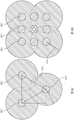
Fig. 8A shows an embodiment of a hexagonal grid template for laser probe placement.
Fig. 8B illustrates an embodiment of a square grid template.
Fig. 8C shows an embodiment of laser exposed areas using a hexagonal grid template with 7mm spacing between grid apertures.
Fig. 8D shows an embodiment of laser exposed areas using a square grid template with a 3mm spacing between grid apertures.
Figure 8E shows a view of the three-part square grid after disassembly.
Fig. 8F is a view of an embodiment of a unitary hexagonal mesh.
Fig. 8G is a view of an embodiment of a three-part square grid.
Fig. 9A-9G illustrate various components of an embodiment of a laser irradiation system kit.
Fig. 10A-10B are photographs of experimental arrangements for testing laser catheters with conical tips and laser catheter assemblies with transmissive tips.
Fig. 11A-11B are graphs showing heating of a laser catheter with a conical tip (11A) and a laser catheter assembly with a circular transmissive tip (11B).
Fig. 12A-12B show thermal images of the distal end of a laser catheter with a conical tip after 6.0W irradiation.
Fig. 12C-12D show thermal images of the distal end of a laser catheter with a dome-shaped tip after 6.0W irradiation.
Figure 13 shows the heating of a conical tipped laser catheter when using an optical fiber with an 18mm diffuser.
Fig. 14A-14I are photographs (scale bar 1cm) of 9 whole sections of a patient's prostate.
Fig. 15 is a graph showing the relative accumulation of nanoparticles in tumor tissue versus healthy tissue samples from two patients.
Detailed Description
Various methods, systems, and devices for treating tumors are disclosed. Some embodiments disclosed herein relate to methods of treating tumors, systems for irradiating tissue and tumors with electromagnetic radiation, components and devices of such systems, and kits for providing systems for irradiating tissue and tumors with electromagnetic radiation. In some embodiments, the system provides non-ablative infrared radiation (e.g., radiation of insufficient intensity to ablate tissue by itself and/or sub-ablative radiation) that is absorbed by the nanoparticles. In some embodiments, the nanoparticles absorb radiation to convert it into thermal energy. In some embodiments, although the infrared radiation itself may be sub-ablative, the thermal energy generated by the nanoparticles is sufficient to cause thermal coagulation, overheating, and/or tissue ablation. Various methods, devices, systems, and kits for treating tumors and ablating tissue are described below to illustrate various examples that may be used to achieve one or more desired improvements. These examples are merely illustrative and are not intended to limit the general inventions presented, as well as the various aspects and features of these inventions, in any way. Further, the phraseology and terminology used herein is for the purpose of description and should not be regarded as limiting. No feature, structure, or step disclosed herein is essential or necessary. Any system or method disclosed herein may exclude one or more of the steps or features described herein.
The optical properties determine how optical wavelength photons interact with biological tissue. These are optical scattering and optical absorption. When a photon encounters a change in refractive index, such as at a cell membrane, scattering occurs. The scattered photons will continue to travel through the tissue, but with a changed direction. Absorption results in the deposition of photon energy into any substance that absorbs it, such as a hemoglobin molecule or organelle. The energy of the absorbed photon is typically converted to heat, which is radiated away from the absorption site.
Absorption of photon energy can cause photocoagulation, which results in the scattering of proteins, resulting in a dramatic increase in optical scattering and a reduction in the ability of light to penetrate tissue. The change of protein from transparent to opaque when heated in a frying pan is a well known example of this phenomenon. Photothermal coagulation, a therapeutic method, may utilize the ability of laser energy transmitted through an optical fiber to interstitially deliver a specific amount of energy into tissue. Laser Interstitial Thermal Therapy (LITT) is a technique that delivers sufficient optical power to directly produce thermal coagulation in tissue. Essentially, optical energy is delivered into the tissue at a rate that is higher than the body's ability to remove the generated heat. This heat can lead to overheating and tissue ablation.
However, the effective treatment depth of LITT and other photon-based treatments may be hindered by light scattering and absorption in the tissue, including that caused by thermal coagulation. Such scattering and absorption may result in an exponentially decreasing light intensity as the distance from the light source to the tissue increases. Yet another limitation is the light intensity or irradiance (in W/cm) when delivered by a one-dimensional source (e.g., a fiber optic diffuser for interstitial delivery of laser light into tissue) 2 Measured) also falls and/or decreases in the radial direction. The end result is that the optical irradiance is higher in the immediate vicinity of the light source delivering it, while the optical irradiance is much lower in the region just outside the immediate area of the light source (e.g., the diffuser). Photon-based phototherapy procedures are also non-specific; the shape of the solidification region varies according to the shape of the energy source, and the volume of the solidification region depends on the total energy of deposition. For example, current laser conduits for photon-based processes use fiber diffusers and 12A power of 15W to create an elliptical coagulated region around the diffuser. Thus, the selectivity of treating the target tissue is low.
In addition, because current systems require high power irradiance, high laser temperatures can occur that can damage and/or deform the laser delivery catheter. Active cooling is used to prevent carbonization of tissue immediately surrounding the laser delivery catheter and/or to prevent instrument damage. However, these systems do not actively regulate the coolant used to cool these laser catheters, and typically allow a flow of room temperature saline-15-20 mL/min in a thin jacket around the fiber diffuser to prevent carbonization of the tissue on the laser catheter. Uncontrolled coolant flow may result in cooling of tissue exposed to the cooling source between laser applications.
Some embodiments disclosed herein relate to methods, devices, systems, and kits that use non-ablative radiation to produce particle-directed photothermal coagulation (e.g., using nanoparticles or other agents). In some embodiments, the disclosed techniques and devices allow for improved selectivity of targeting and effectively treating tissue. Some embodiments disclosed herein relate to systems and devices for generating radiation at a site where photothermal coagulation, overheating, and/or tissue ablation are desired.
In some embodiments, the methods and devices involve particle-directed (e.g., with nanoparticles) photothermal coagulation for treatment of tumors. In some embodiments, the method involves injecting the nanoparticles into a patient with a tumor (or another tissue to be targeted). In some embodiments, the nanoparticles are allowed to accumulate in the tumor for a defined period of time. In some embodiments, once the nanoparticles accumulate at the site of interest, the laser probe of the laser catheter assembly is positioned (e.g., inserted, placed, etc.) in or near the site of interest (e.g., in or near a tumor). In some embodiments, the laser catheter assembly is activated to deliver electromagnetic radiation (e.g., ultraviolet light, visible light, near infrared light, far infrared light, microwaves, etc.) to the nanoparticles. In some embodiments, the radiation is infrared radiation. In some embodiments, the laser catheter assembly delivers radiation that is not strong enough to cause photothermal coagulation (e.g., radiation that is non-ablative radiation and/or sub-ablative) overheating and/or tissue ablation by itself (e.g., in the absence of nanoparticles). In some embodiments, the radiation intensity is converted to thermal energy by the nanoparticles. In some embodiments, the heat converted by the nanoparticles is sufficient to cause ablative overheating, tissue coagulation, and/or tissue ablation.
In some embodiments, the nanoparticles used in the disclosed methods are designed to absorb infrared radiation and convert it to thermal energy. In some embodiments, gold nanoshells (e.g., AuroShells, etc.) are used as nanoparticles that convert sub-ablative infrared radiation to an ablation temperature. While gold nanoshells (e.g., AuroShells, etc.) are used as representative nanoparticles for illustration, it should be noted that any nanoparticle (or microparticle) that absorbs infrared photons and converts those photons to thermal energy is contemplated. Without being bound by any particular theory, it is believed that absorption of photons by the nanoshells effectively extinguishes the photons and causes their energy to be converted into heat that is emitted into the surrounding tissue. When a photon is scattered by a particle (e.g., not absorbed), the scattered photon can be used for absorption elsewhere (e.g., through tissue, another nanoshell, etc.). The conversion nanoparticles comprise in particular: nanoshells (including gold-shelled silica core nanoshells (such as Auroshells), gold-gold sulfide nanoshells and other variations), solid nanospheres (gold, silver, etc.), metal nanorods (gold, silver, etc.), nanostars, hollow nanoparticles, nanocages, oval "nano" carbon particles, fullerenes, carbon fullerenes, metal nanoparticles, metal colloids, carbon particles, carbon nanotubes, buckyballs, and any combination thereof.
In some embodiments, the methods disclosed herein are used to treat a target tissue. In some embodiments, the target tissue is tumor tissue. In some embodiments, the tumor target region comprises a tumor caused by cancer. In some embodiments, the tumor is a tumor caused by colorectal cancer, brain cancer, lung cancer, breast cancer, head and neck cancer, pancreatic cancer, ovarian cancer, melanoma cancer, prostate cancer, and other forms of cancer. In some embodiments, the techniques disclosed herein are suitable for treating tumors in tissue and/or for preserving the function of healthy tissue while destroying underlying tumor tissue. For example, in some embodiments, the techniques and devices disclosed herein can be used for specific target tumor tissues or dysfunctional tissues. Loss of function of certain healthy tissues can have a serious impact on the quality of life of a patient. For example, surgical procedures that remove cancerous tumor tissue from the throat may result in speech loss. Surgical procedures to remove cancerous tumor tissue from the prostate may result in loss of sexual function. In current ablation methods, tissue is heated based on the placement of a heating instrument in the tumor. The heating element is activated, killing tissue surrounding it, including healthy tissue. In some embodiments, the treatments disclosed herein can partially, mostly, and/or completely preserve the structure and/or function of the underlying healthy tissue that is not diseased, to facilitate or mostly preserve the normal function of those underlying tissues.
In some embodiments, the method involves systemically injecting (e.g., infusing) the nanoparticles into the patient. Systemic introduction may involve directing the nanoparticles to a site within the circulatory system and/or body but away or distant from the target site. In some embodiments, the nanoparticles can be introduced to the patient via a parenteral route of administration (e.g., via intravenous, intramuscular, subcutaneous, intralesional, intraperitoneal, etc. injection). These sites may be located in areas of the patient's body that are not proximal to the treatment site (e.g., at body sites other than tumor sites). For example, nanoparticles accumulate preferentially within tumors, primarily as a result of their size and leakage from tumors, disorganization, and passive extravasation of immature vasculature; this phenomenon is known as the "high permeability and retention" (EPR) effect. In some embodiments, this passive accumulation allows for targeted deposition of the radiation transducer and provides tumor-specific photothermal coagulation therapy.
In some embodiments, the nanoparticles are allowed to passively accumulate at the tumor after being directed to the body. In some embodiments, this passive accumulation is achieved by the passage of a defined period of time. In some embodiments, after infusion and/or injection, the nanoparticles are allowed to accumulate in the tumor for a period of time ranging between equal to or at least about 12 hours and/or less than or equal to about 36 hours. In some embodiments, the nanoparticles are allowed to accumulate at the tumor site for at least the following period of time: about 12 hours, 24 hours, about 36 hours, or a range that includes and/or spans the aforementioned values.
In some embodiments, the nanoparticles accumulate in the perivascular spaces of the tumor neovasculature and serve as a focal point for laser energy. In some embodiments, after accumulation at the site of interest, the nanoparticles are heated using laser and/or electromagnetic energy. In some embodiments, such laser energy (e.g., electromagnetic energy) heats the nanoparticles to a temperature sufficient to cause thermal coagulation, overheating, and/or ablation of the target tissue.
In some embodiments, the laser irradiation system 100 shown in fig. 1 is utilized to generate laser energy at the target site for treatment. In some embodiments, as shown in fig. 1, the laser illumination system 100 includes a laser catheter assembly 101 (e.g., a laser illuminator). In some embodiments, the laser irradiation system further comprises one or more of an irradiation system 200 and a cooling system 300. In some embodiments, the illumination system 200 includes an optical fiber 202 and a laser source 203. In some embodiments, the optical fiber 202 is configured to be connected to a laser source 203, in optical communication with the laser source, and/or to receive laser energy from the laser source 203. In some embodiments, the laser source, optical fiber, and/or laser catheter are in optical communication as disclosed elsewhere herein. In some embodiments, the cooling system includes one or more of a coolant reservoir 305, a coolant pump 307, and/or a coolant recovery bag 309. In some embodiments, the coolant reservoir, the laser catheter assembly, and/or the coolant recovery bag are configured to be in fluid communication with one another, as disclosed elsewhere herein. In some embodiments, the laser irradiation system includes a laser catheter assembly but lacks one or more other features, such as the irradiation system and/or the coolant delivery system and components thereof.
In some embodiments, as shown in fig. 1, laser catheter assembly 101 is configured to receive a coolant via coolant inlet connector 104. In some embodiments, the laser irradiation system 100 includes a coolant reservoir 305 (e.g., a bag, a bottle, etc.). In some embodiments, the coolant reservoir 305 is in fluid communication with the coolant inlet connector 104 via a coolant inlet conduit 306. In some embodiments, coolant from coolant reservoir 305 is delivered into laser conduit assembly 101 via coolant inlet connector 104 using coolant pump 307. In some embodiments, the coolant inlet conduit 306 has an inlet conduit connector 310 configured to interact with the coolant inlet connector 104.
In some embodiments, laser catheter assembly 101 is configured to discharge coolant via coolant outlet connector 108. In some embodiments, the laser irradiation system 100 includes a coolant recovery bag 309 (e.g., bag, bottle, etc.). In some embodiments, the coolant recovery bag 309 is in fluid communication with the coolant outlet connector 108 via a coolant outlet conduit 311. In some embodiments, coolant from laser catheter assembly 101 is delivered into coolant recovery bag 309 via coolant outlet connector 108. In some embodiments, the coolant outlet conduit 311 has an outlet conduit connector 312 configured to interact with the coolant outlet connector 108.
In some embodiments, as shown in fig. 2A, the inlet connector and the outlet connector of the laser catheter assembly 101 are of different genders. In some embodiments, such a configuration may prevent improper connection and/or mismatch (e.g., prevent back connection) of the inlet and outlet connectors of the laser catheter assembly 101 with the coolant supply and recovery attachments. For example, as shown in fig. 1, the coolant inlet connector 104 may be a female connector having a female receiving portion 104', and the coolant supply inlet 310 may have a male connection with a male protrusion 315 and an optional shield 316 (e.g., a cap, a threaded shield, etc.), while the coolant outlet connector 108 may be a male connector having a male protrusion 108' and an optional shield 108 "(e.g., a cap, a threaded shield, etc.), and the coolant outlet conduit connector 324 may have a female connection with a female receiving portion 325. In some embodiments, the coolant inlet connector 104 may be a male connector, while the coolant outlet connector 108 may be a female connector (not shown). In some embodiments, the inlet connector 104 and the outlet connector 108 may be color coded to match colors (not shown) on the inlet tubing connector 310 and the outlet tubing connector 324 instead of or in addition to having different genders. For example, in some embodiments, the inlet connector 104 and the inlet conduit connector 310 may be one color (e.g., red, orange, yellow, green, cyan, blue, indigo, violet, purple, magenta, pink, brown, white, gray, black) and the outlet connector 108 and the outlet conduit connector 324 may be another different color (e.g., red, orange, yellow, green, cyan, blue, indigo, violet, purple, magenta, pink, brown, white, gray, black). In some embodiments, the male and female connectors may be luer connectors (which may include ISO 594 compliant luer fittings in some embodiments). In some embodiments, the inlet connector and the outlet connector do not have different genders.
As shown in fig. 2A and 2B, in some embodiments, laser catheter assembly 101 includes an introducer probe 113. In some embodiments, as shown in fig. 2A, the laser catheter assembly 101 includes one or more of an exit arm unit 125, an exit arm 126, and an entrance arm unit 130, and an entrance arm 131. In some embodiments, the introducer probe 113 is an elongated tube that extends from a proximal introducer probe connector seal 135 (e.g., seal, sheath, etc.) to a sealed end 115 of the introducer probe 113.
In some embodiments, introducer probe 113 includes an outer tubular portion 114. In some embodiments, as shown in fig. 2A and 2B, the outer tubular portion 114 is a continuous material (e.g., a single piece molded from a single material, a unitary structure, etc.). In some embodiments, the outer tubular portion 114 is transparent or substantially transparent to certain wavelengths of electromagnetic radiation, for example, one or more of ultraviolet light, visible light, near-infrared light, far-infrared light, and/or microwave radiation.
In some embodiments, outer tubular portion 114 includes a sealed end 115. In some embodiments, sealed end 115 is clear, optically and/or infrared transparent, and/or substantially optically and/or infrared transparent. In some embodiments, sealed end 115 is transparent or substantially transparent to certain wavelengths of electromagnetic radiation, for example, one or more of ultraviolet light, visible light, near-infrared light, far-infrared light, and/or microwave radiation. In some embodiments, sealed end 115 is transmissive. In some embodiments, sealed end 115 allows transmission of electromagnetic radiation from laser source 203 therethrough (e.g., via diffuser tip 204 as disclosed elsewhere herein). In some embodiments, as shown in fig. 2A-2, the sealed end 115 is shaped to distribute light from the optical fiber 202 into alignment with the introducer probe 113, into a tapered profile 140 expanding outward and distally from the sealed end 115, or into a hemispherical profile 141 expanding outward and distally from the sealed end 115. In some embodiments, the distribution of light (cone or hemisphere) is diffused such that the amount of radiation at a given distance (e.g., at points 140A and 140B and/or at points 141C and 141D) is substantially or about the same intensity over the distribution. In some embodiments, end 115 is configured to allow radiation and/or light to pass therethrough without substantially absorbing the radiation and/or light.
In some embodiments, the fiber tip 204 is configured to prevent radiation from passing through the tip and/or the fiber tip 204 substantially blocks radiation. In some embodiments, the diffuser tip 223 is configured to emit most and/or substantially all and/or all radiation received transversely (e.g., laterally from the diffuser tip) via the radiation source rather than along the path of the optical fiber 202 (e.g., through the optical fiber tip 204). In some embodiments, a diffusing tip that emits radiation laterally (e.g., sideways) advantageously allows for treatment of tissue adjacent to the diffuser tip 223. In some embodiments, such a configuration prevents and/or reduces the amount of heating and/or irradiation of tissue just in front of the fiber tip 204.
In some embodiments, the diffuser tip 223 is configured to distribute electromagnetic radiation laterally from the introducer probe, as described elsewhere herein. In some embodiments, the intensity of the electromagnetic radiation from the diffuser is about or substantially equal at equal distances from the diffuser tip 223. In some embodiments, the light emitted from the introducer probe 113 is distributed and/or unfocused. In some embodiments, the light emitted from the introducer probe 113 is substantially evenly distributed. In some embodiments, because the light is distributed from the diffuser along the surface of the diffuser, the emitted radiation does not cause shadows (e.g., locations where the radiation is blocked by components of the laser duct, etc.). In some embodiments, the laser catheter assembly and/or diffuser tip lack a focusing lens and do not include a mirror.
In some embodiments, the sealing end is dome-shaped (e.g., hemispherical, having a hemispherical shape, spherical-like, dome-shaped, etc.). In some embodiments, the sealed end is transmissive, as described elsewhere herein. In some embodiments, the transmissive device allows all, substantially all, or a portion of the electromagnetic radiation from the diffuser tip 223 to pass through. In some embodiments, the outer tubular portion 114 is continuous with the sealing end 115 (e.g., the sealing end and the outer tubular portion are a single piece, unitary structure, etc. molded from a single material). In some embodiments, the transmissive sealed end 115 has the benefit of reducing heat build-up in the probe tip. This feature helps to avoid probe melting and also allows laser light to be distributed into the tissue along the direction of the probe. In some embodiments, the sealed end is not tapered and/or is not ground material (e.g., a scattering material, an opaque or substantially opaque material, etc.). In some embodiments, it has been found that the circular and/or conical configuration does not allow radiation to pass through the introducer probe. In some embodiments, it has been found that the grinding and/or tapering configuration can concentrate the radiation, causing hot spots and heating that can lead to warping and/or charring of the probe and/or burning of the tissue surrounding the probe.
In some embodiments, the dome-shaped tip is prepared using radio frequency. In some embodiments, the dome tip is formed from a nylon extrusion that is placed on a mandrel and then inserted into a stainless steel mold. In some embodiments, the die is heated using radio frequency energy, while the extrusions are simultaneously pushed into the cavity using a pneumatically actuated clamp, which causes the ends of the extrusions to reflow/reform over one end of the mandrel. In some embodiments, the RF machine is set with extrusion specific temperature, pressure and time settings so it can make very repeatable tips. In some embodiments, the tip is not hemispherical, but another shape that allows radiation to pass without significant accumulation of heat or concentration of radiation (e.g., a rounded cube end shape, a rounded cylinder end shape, a cylinder end shape, etc.).
In some embodiments, as shown in fig. 2A-1, the outer tubular portion 114 includes a lumen 116 (e.g., a first lumen). In some embodiments, the inner tube 117 is located within the first lumen 116. In some embodiments, inner tube 117 includes a second lumen 118.
In some embodiments, as shown in fig. 2A and 2B, laser catheter assembly 101 is configured to receive coolant via coolant inlet connector 104, through catheter inlet conduit 132, through inlet arm unit 131, and into the body of inlet arm unit 130. The coolant then travels to the open cell 119 via the inner tube 117, through the first lumen 116, through the outlet arm unit 125, through the outlet arm, into the catheter outlet conduit, and out via the coolant outlet connector 108. In other words, in some embodiments, one or more of the coolant inlet connector 104, the catheter inlet conduit 132, the inlet arm unit 131, the inlet arm unit 130, the inner tube 117, the open pool 119, the first lumen 116, the outlet arm unit 125, the outlet arm, the catheter outlet conduit, and/or the coolant outlet connector 108 are in fluid communication.
In some embodiments, introducer probe 113 extends from a proximal end to a distal end where a sealed dome-shaped end 115 of outer tubular portion 114 is located. In some embodiments, the inner tube 117 terminates a distance away from the sealed dome-shaped end 115, leaving an open pool 119 at the distal end of the introducer probe 113. In some embodiments, the distal end of the diffuser tip 223 terminates at or substantially at the distal end of the inner tube 117 when the optical fiber is positioned in the introducer probe 113. In some embodiments, a portion of the diffuser tip 223 protrudes from the inner tube 117 in the open cell 119. In some embodiments, such protrusion allows a greater amount of electromagnetic radiation to penetrate the sealed end 115 of the introducer probe 113. In some embodiments, the open cell provides a region around which coolant can flow without being substantially restricted by the fiber tip 204 (e.g., blocking and/or restricting the flow of coolant within the lumen).
In some embodiments, the laser catheter assembly 101 is configured to receive the optical fiber 202 into the introducer probe 113 via the end aperture 120. In some embodiments, inner tube 117 is configured to receive optical fiber 202 within second lumen 118. In some embodiments, fiber optic connectors 222 couple with features on end aperture 120 to provide a fluid tight seal. In some embodiments, the coupling secures the diffuser tip 223 in position within the introducer probe 113. In some embodiments, the laser catheter assembly 101 receives only one optical fiber 202, and the introducer probe 113 and the inner tube 117 are sized and/or configured to receive only a single optical fiber tip 204 and/or diffuser tip 223.
In some embodiments, the second lumen 118 is in fluid communication with the coolant inlet connector 104, as described elsewhere herein. In some embodiments, the first lumen 116 is in fluid communication with the coolant outlet connector 108, as described elsewhere herein. In some embodiments, when the optical fiber 202 is positioned within the second lumen 118, the laser catheter assembly is configured to allow coolant to enter the first lumen 116 from the coolant inlet connector 104 through the second lumen 118 and exit the coolant outlet connector 312.
In some embodiments, the lumen of the laser catheter assembly 101 and the introducer probe 113 may be formed of a material such as nylon, PA12 nylon, or similar materials. In some embodiments, PA12 nylon advantageously allows the introducer probe 113 to pass smoothly through the introducer and tissue as compared to materials such as polycarbonate.
In some embodiments, as shown in fig. 2A, the introducer probe 113 includes a printed "hash" mark 121. In some embodiments, the introducer probe 113 is graduated. In some embodiments, the hash marks and/or graduations may clearly mark the depth of penetration of the probe into the tissue (and/or the distance the probe is withdrawn from the tissue). In some embodiments, the hash marks are spaced apart by a distance equal to or less than: about 4mm apart, about 8mm apart, about 12mm apart, values in between the foregoing, or ranges spanning and/or including these values. In some embodiments, alternating hash marks and dots at a distance allow the laser catheter assembly 101 to be pulled back through tissue for multiple treatments with various optical diffusers (e.g., 1cm diffuser, 1.8cm diffuser, etc.), as discussed elsewhere herein. In some embodiments, these graduations and/or hash marks allow a user to directly visualize the probe depth. In some embodiments, these graduations and/or hash marks allow fine control of the position of the probe, thereby allowing effective and/or controlled ablation of tissue. In some embodiments, the length of the introducer probe is equal to or less than about: 50cm, 30cm, 20cm, 10cm, values between the above, or ranges including and/or spanning these values.
In some embodiments, the optical fiber 202 includes a diffuser tip. In some embodiments, the diffuser tip 223 is a portion of the optical fiber 202 that has radiation scattering features (e.g., topography, bumps, roughness, pits, etc.) that encourage and/or allow radiation (e.g., laser light, photons, radiation) to exit the optical tip in different directions (e.g., scatter, diffuse, etc.). In some embodiments, these features are provided as a gradient along the diffuser and are less dense near the laser source 203 and more dense the farther away the laser source 203. In some embodiments, the density gradient encourages a substantially uniform distribution of radiation along the entire diffuser tip. In some embodiments, the diffusing portions 223 of the optical fibers 202 may have different lengths. In some embodiments, the length of the diffusing portion of the optical fiber may be equal to or less than about: 50mm, 30mm, 18mm, 10mm, values between the foregoing values, or ranges including and/or spanning these values. In some embodiments, a longer diffuser allows for treatment of a larger tumor volume in the same amount of time by using a higher laser power and distributing it along the longer diffuser. In some embodiments, the use of a smaller diffusive tip allows for the use of less laser power and allows for the treatment of smaller sized tumors with greater specificity. In some embodiments, a single treatment may use diffusers of various sizes to customize the treatment to a particular region of the body and for a particular tumor size. In some embodiments, as shown in fig. 3B, the optical fiber is soft and/or flexible and is configured to move within the introducer probe without kinking or breaking. In some embodiments, the optical fiber has a length sufficient to allow the laser source to be placed out of the way during operation. In some embodiments, the length of the optical fiber is equal to or less than: 1m, 2m, 3m, 5m, or a range that includes and/or spans the aforementioned values.
To illustrate one or more improvements that may be realized with the disclosed design features of the laser catheter assembly, the following exemplary description is provided. In some embodiments, hash marks located along the introducer probe enable the user to determine the location of the laser catheter diffuser tip and the extent of treatment to the targeted tumor. In some embodiments, computed tomography may be utilized to determine the initial positioning of the introducer probe (e.g., the depth of insertion into the body along the z-axis and the lateral positioning along the x-and y-axes). Once the initial position is reached, the treatment position can be found using the hash mark. The probe can be withdrawn from one position to the next at a set pitch determined by the scale on the probe. The printing on the laser catheter assembly provides the user with a "depth gauge" to know how far the laser catheter assembly has penetrated into the tissue or how far the stylet has been withdrawn from the starting position. In some embodiments, for example, an 8mm spacing between hash marks and an 8mm spacing between "dots" in the middle of the hash marks provides a "scale" of 4mm spacing to allow for accurate "pull back". In some embodiments, a grid is used to assist in the proper positioning of the diffuser tip of the laser catheter assembly laterally within the tissue, as described elsewhere herein. In some embodiments, 8mm pullback allowed for a 10mm grid is used, as disclosed elsewhere herein. These markers provide a direct way for the user to know the depth to which the laser catheter is located in the target tumor or tissue, and provide a direct way to gradually pull back the catheter to create a continuous ablation zone along the catheter trajectory.
In some embodiments, as shown in fig. 3A and 3B, the optical fiber may include an optical fiber connector 122 (e.g., a luer connector, which may include an ISO 594 compliant luer fitting in some embodiments). In some embodiments, the fiber optic connectors are joined at a fixed distance from the distal end of the fiber stub 204.
In some embodiments, the fiber optic connector 122 is configured to engage with the end aperture 120 of the laser catheter assembly 101. In some embodiments, the fixed positioning of the fiber optic connector 122 may ensure proper retraction of the diffuser tip within the laser catheter assembly 101. In some embodiments, securing the optical fiber 202 within the laser catheter assembly 101 may help prevent tip melting and may ensure proper coolant flow around the diffuser. In some embodiments, securing the optical fiber may help prevent the diffuser tip from sliding out of the laser catheter assembly 101. In some embodiments, securing the optical fiber 202 within the laser catheter assembly 101 may help ensure that the laser light is properly diffused out of the diffuser tip (e.g., by preventing a portion of the diffuser from exiting the inner tube 117 or preventing the diffuser from bottoming out against the probe 113 tip, e.g., where it may block the flow of coolant and/or cause uneven distribution of the emitted light). In some embodiments, the fixed optical fiber may also advantageously provide sufficient light diffusion from the tip of the introducer probe 113 to allow treatment of tissue in front of the tip (other than tissue laterally adjacent to the diffuser tip).
In some embodiments, the optical fiber has a total length (in meters) less than or equal to about: 2. 3.5, 5, or a range that includes and/or spans the aforementioned values. Such a length advantageously reduces clutter in an operating room, as in some embodiments, the entire laser irradiation system as disclosed herein can have dimensions that allow it to be completely housed in the operating room (e.g., in a sterile environment).
In some embodiments, the coolant supply system of laser irradiation system 100 includes a coolant reservoir 305, a coolant inlet conduit 306, and a coolant pump 307. In some embodiments, a coolant supply system supplies a coolant (e.g., saline, water, etc.) to laser catheter assembly 101. In some embodiments, the coolant helps prevent early onset of photocoagulation adjacent to the laser catheter assembly 101 and the introducer probe 113. Early onset photocoagulation may adversely limit the light penetration of laser radiation into the tissue and/or render tumor-specific the optically-excited nanoparticles ineffective.
Fig. 4 shows an embodiment of the coolant inlet conduit 306. In some embodiments, the length of the coolant inlet conduit 306 may be less than or equal to: about 3m, about 4m, about 5m, about 10m, values between the foregoing, or ranges spanning and/or including these values. In some embodiments, the length of the coolant inlet conduit 306 reduces clutter in the operational setting. In some embodiments, the coolant inlet conduit 306 is comprised of flexible Tygon tubing (polyvinyl chloride tubing or the like, e.g., flexible tubing) enabling it to be clamped into the cooling pump at any location along its length. In some embodiments, the diameter of the tube is about 1/8 ". In some embodiments, the diameter of the tube is less than about: 1/12 ", 1/8", 1/4 ", or a range including and/or spanning the aforementioned values. In some embodiments, such a diameter allows for smaller pump head spacing, greater coolant flow control, and/or greater consistency of flow between tube sets. In some embodiments, this feature eliminates the need for external flow restrictors and meters in the return line. In some embodiments, this feature allows for more precise control of low flow (e.g., equal to or less than about 8mL/min) coolant flow used during certain methods described herein. In some embodiments, flow rates in mL/min that can be achieved are less than or equal to 2, 4, 8, 10, or ranges that include and/or span the above values. Fig. 5A and 5B illustrate an embodiment of a coolant recovery bag. As shown in fig. 5B, the coolant recovery bag may include a flexible length of tubing configured to be attached to the laser catheter assembly.
In some embodiments, the coolant supply group designs disclosed herein advantageously eliminate or reduce the problem of the inability to position the coolant pump relative to the reservoir supplying the coolant. In some embodiments, the coolant supply system may be manufactured from a continuous length of tubing, thereby reducing the number of parts and complexity. In some embodiments, the use of the inner diameter polyvinyl chloride tubes disclosed herein advantageously allows for the control of low flow (e.g., 8mL/min) coolant flow.
In some embodiments, the coolant pump 307 has a flow regulator that can be calibrated to default to a given speed in order to produce a given flow. In some embodiments, the pump is a peristaltic pump (e.g., Langer BT 100-1L). In some embodiments, the flow delivered by the pump is less than or equal to about 0.002, 0.01, 0.1, 1, 20, 50, 100, 500, or a range including and/or spanning the above values in mL/min. In some embodiments, the coolant pump 307 has quiet operating characteristics and operates at decibel levels equal to or less than approximately 10, 20, 30, 40, 50, 60, 70, 80, or a range including and/or spanning the aforementioned values.
In some embodiments, the quiet feature of such pumps is beneficial because the disclosed system may be placed in an operating room with a patient.
In some embodiments, the pump 307 may be connected to an actuation device (e.g., a foot pedal, panel, button). In some embodiments, the actuation means may be turned on or off by a user (e.g., a physician or technician operating the pump). In some embodiments, the laser source is connected to an actuation device (e.g., foot pedal, panel, button) that may be the same or different from the actuation device that controls the pump. In some embodiments, where the actuating means of the pump and the laser source are the same, the actuating means may have one or more toggle switches (e.g., buttons or panels) that allow a user to separately or simultaneously control the flow of coolant through the laser conduit and/or control the laser source to emit laser light. In some embodiments, where the laser source and the pump are activated simultaneously, the actuation means may have a single switch for simultaneously turning the laser source and the pump on or off. In some embodiments, where the laser source and pump are activated separately, the actuator may have different switches to activate one device at a time.
In some embodiments, the actuator connection allows coolant flow when the laser is active and stops coolant flow when the laser is inactive. In some embodiments, in addition to reducing the volume of coolant consumed (e.g., number of coolant bag replacements, etc.), such a feature may advantageously prevent tissue pre-cooling between laser treatments. In some embodiments, the pump may be programmed to have a default flow rate when the laser is active. In some embodiments, controlling the default flow rate of the pump is beneficial for the disclosed methods, which can use nominal sub-ablative laser doses without utilizing real-time temperature monitoring. In some embodiments, the default flow rate in mL/min is less than or equal to about: 0.002, 0.01, 0.1, 1, 5, or a range including and/or spanning the above values. The predetermined flow rate allows the user to remove heat at a predetermined rate. In some embodiments, automatically stopping coolant flow when the laser is off helps to avoid freezing tissue. Flowing coolant through the laser catheter assembly between laser treatments (e.g., when the laser is turned off) freezes surrounding tissue (e.g., from at or about 30-37 ℃) to the temperature of the coolant (e.g., at or about 21-23 ℃). In some embodiments, this has the effect of producing a therapeutic deficit, as the additional temperature gradient must be overcome in order to produce tissue ablation. In some embodiments, the combination of disclosed features allows for tight regulation of cooling. In some embodiments, such temperature control may advantageously delay tissue coagulation adjacent the laser catheter until the timed treatment is over. In some embodiments, the delay in photocoagulation may assist in treating tumor tissue at longer distances from the laser catheter, since the nanoparticles are activated only by optical photons, since the increase in optical scattering due to coagulation effectively attenuates optical penetration into the tissue.
In some embodiments, coolant recovery bag 309 collects coolant after a single pass through laser catheter assembly 101. In some embodiments, coolant recovery bag 309 is connected to laser catheter assembly 101 via coolant outlet tubing 311 and outlet tubing connector 324 (see fig. 5A-5B). In some embodiments, the volume of the coolant recovery bag 309 is greater than or equal to about 1.5 liters, 2.0 liters, or 3 liters. In some embodiments, such a volume allows for collection during the entire duration of treatment. In some embodiments, the pump is activated using a foot switch and the treatment duration is equal to or at least about 62 standard 3 minute treatments in 8 mL/min. In some embodiments, the coolant recovery bag 309 has an integral 1.5 meter tube set, which allows it to be placed at the bedside.
In some embodiments, the laser catheter assembly is guided into a tumor or an organ comprising tumor tissue using a trocar assembly 400 comprising a trocar 425 and a sheath catheter 426 (catheter sheath) that is sleeved around the trocar 425. As shown, in fig. 2B, in some embodiments, the introducer probe 113 is soft and/or flexible (e.g., a 25cm length probe may be looped round without kinking). In some embodiments, the tip is constructed of a material that allows bending, which advantageously allows the tip to bypass obstacles at the tissue. In some embodiments, the flexible material of the probe advantageously resists adhesion to tissue and/or is non-tacky and/or substantially non-tacky, as disclosed elsewhere herein. In some embodiments, the introducer probe 113 has a length (e.g., from proximal to distal end) less than or equal to about: 300mm, 240mm, 200mm, or a range that includes and/or spans the aforementioned values. In some embodiments, the introducer probe has a width of less than or equal to about: 2mm, 1mm, 0.5mm, or a range that includes and/or spans the aforementioned values.
In some embodiments, to facilitate guidance of the introducer probe 113, a trocar sheath assembly 427 is used to insert the introducer probe 113 into tissue, as shown in fig. 6A-2. In some embodiments, as shown in fig. 6A, a trocar sheath assembly 427 can include a trocar 425 and a sheath catheter 426. In some embodiments, trocar 425 includes trocar lumen 428. Fig. 6A-1 show an aliquot cross-sectional view of the trocar assembly 400 with the lumen 428 exposed. Fig. 6A-4 show end views of the catheter sheath assembly 427. Fig. 6B and 6B-1 show the trocar 425 without the sheath, with fig. 6B-1 showing an isometric cross-sectional view. In some embodiments, the trocar 425 further includes a trocar handle 429, as shown. In some embodiments, the trocar handle 429 is ergonomic. In some embodiments, the trocar handle 429 has one or more finger holds 431 that facilitate manipulation of the trocar 425 during placement. In some embodiments, the trocar handle 429 allows placement of a trocar through tissue of a patient and/or positioning of the trocar assembly 427 at a treatment site within a patient.
In some embodiments, the trocar 425 includes a three-sided cannula and/or needle 430. Fig. 6A-3 show an enlarged view of the catheter tip 430 with the sheath 426. Fig. 6B-2 shows an enlarged view of the catheter tip 430 without the sheath 426. Fig. 6B-3 show a front view of trocar tip 430. In some embodiments, the three-sided trocar tip 430 prevents tissue pulling as the trocar is pushed through the patient's tissue. In some embodiments, the bevel needle may be pulled to one side of the bevel when passing through tissue. In other embodiments, a beveled needle is used as a trocar (not shown). Fig. 6B-4 show an end view of trocar 429.
In some embodiments, after insertion into the treatment site, trocar 425 is removed from the patient. In some embodiments, the catheter sheath 426 remains within the patient when the trocar 425 is removed. In some embodiments, the catheter sheath 426 may then be used to position the laser catheter assembly 101 and the introducer probe 113 in the treatment site.
In some embodiments, the methods disclosed herein include inserting a trocar assembly 427 comprising a trocar 425 and a catheter sheath 426 that is sleeved around the trocar 425 into the patient at an insertion point (e.g., a first insertion point). Such insertion is illustrated in the figures of fig. 7A-7J with a test specimen 700 representative of a target tissue (e.g., tumor, etc.). In this case, the test sample was raw chicken breast. The test sample is used as a model of a tumor or an organ containing a tumor. Fig. 7A shows a test specimen and a trocar sheath assembly 427 within a protective cover 433. Fig. 7B shows trocar sheath assembly 427 removed from protective cover 433. As shown in fig. 7C, in some embodiments, a trocar sheath assembly 427 can be inserted into a proximal side 701 (where proximal refers to the position of the user and/or the insertion point) of a target tissue (e.g., test specimen 700). In some embodiments, as shown in fig. 7D, a trocar sheath assembly 427 is inserted through the body of the target tissue to the distal side 702 or substantially distal side of the target tissue 700. In some embodiments, the trocar sheath assembly can be placed at a location intermediate the proximal and distal sides of the target tissue. In fig. 7D, the trocar 425 is visible at the distal side 702 of the target tissue.
As shown in fig. 7E, in some embodiments, once the trocar catheter assembly reaches the distal side of the target tissue 702, the trocar 425 may be removed, leaving the catheter sheath 426 in place. In some embodiments, proper positioning of the trocar sheath assembly 427 can be accomplished using MRI, ultrasound, or other real-time imaging methods (e.g., computed tomography).
In some embodiments, as shown in fig. 7F, the introducer probe 113 of the laser catheter assembly 101 may be prepared for insertion into a catheter sheath. As shown, when the laser is activated, there is a radius of irradiation 111 around the diffuser tip. In some embodiments, the optical fiber 202 is positioned within the laser catheter assembly 101 prior to inserting the introducer probe 113 into the catheter sheath 426. In some embodiments, the optical fiber 202 is secured in the laser catheter assembly 101 via engagement of the fiber connector 222 with the end aperture 220.
In some embodiments, as shown in fig. 7G, the introducer probe 113 of the laser catheter assembly 101 may be inserted into a catheter sheath 426. In some embodiments, the catheter sheath 426 includes an insertion port 432 that facilitates insertion of an instrument, such as the introducer probe 113. In some embodiments, after the introducer probe 113 reaches the proper location in the target tissue, the sheath 426 may be withdrawn slightly proximally of the target tissue 700, exposing the introducer probe 113 and/or diffuser tip 223. In some embodiments, where the introducer sheath is transparent to the radiation emitted by the laser source, the introducer sheath need not be withdrawn to expose the introducer probe 113. In some embodiments, the graduations of the introducer probe may be visible through the catheter sheath 426 to allow for easy visualization of the depth of insertion into the patient during the procedure.
As shown in fig. 7G, the laser source can be activated to illuminate the diffuser tip 223, thereby forming an irradiated region 710 of the target tissue 700. The first region is irradiated for a defined period of time, at which time the catheter sheath 426 and introducer probe 113 may be withdrawn slightly toward the proximal side 701 and away from the distal side 702 of the target tissue 700, thereby exposing a second region of the target tissue for treatment (second irradiated region 712). In some embodiments, the withdrawal/irradiation process may be repeated multiple times depending on the size of the target tissue. As shown in fig. 7I, in some embodiments, a third region (third irradiation position 712) may be irradiated, and so on. In some embodiments, the hashed indicia 121 of the laser catheter assembly 101 allows the user to determine the appropriate location of the first, second, third, fourth, etc. regions for irradiation when the introducer probe 113 is withdrawn.
In some embodiments, the introducer probe 113 and/or the introducer probe and the catheter sheath 426 are incrementally withdrawn from the target tissue at a distance equal to or less than about 4mm, about 8mm, about 12mm, values therebetween, or a range spanning and/or including these values. In some embodiments, the distance between the irradiated regions of the target tissue is equal to or less than: about 4mm apart, about 8mm apart, about 12mm apart, values between the aforementioned values, or ranges spanning and/or including these values. In some embodiments, the distance between the irradiation zones is determined using a scale on the introducer probe. In some embodiments, the trocar sheath assembly 427 can be reinserted into another region of the target tissue (e.g., a second insertion point disposed laterally), and the irradiation and retraction process described above can be repeated. In some embodiments, the laser assembly is repositioned to a different region of the tumor after irradiation.
In some embodiments, for the test samples shown in fig. 7A-7J, a method of treating one or more tumors in a target region (e.g., a tumor in an organ or gland) can include a step for positioning a trocar sheath assembly 427 within a patient. In some embodiments, the trocar sheath assembly is positioned by passing the trocar assembly through, for example, a prostate tumor such that the trocar assembly passes through a proximal face of the tumor (toward a user inserting the trocar sheath assembly) and terminates distal of the tumor (away from the user inserting the trocar sheath assembly). In some embodiments, insertion of the trocar sheath assembly from the proximal side to the distal side of the tumor forms a first pathway within the tumor. In some embodiments, the method of treating a tumor may include the steps of removing the trocar from the patient and leaving the catheter (e.g., catheter sheath 426) in the patient within the first pathway, as described with respect to the test sample of fig. 7A-7J. In some embodiments, a laser catheter assembly 101 (e.g., a laser illuminator assembly) may be acquired. In some embodiments, the laser catheter assembly 101 may include one or more of an introducer probe 113 and an optical fiber 202, as discussed elsewhere herein. In some embodiments, the introducer probe 113 (e.g., a laser introducer probe) includes a first lumen and terminates in a sealed dome-shaped end configured to allow laser transmission. In some embodiments, the introducer probe includes an inner tube positioned within a first lumen of the introducer probe. In some embodiments, the inner tube comprises a second lumen. In some embodiments, the optical fiber may be positioned within the second lumen. In some embodiments, the optical fiber may transmit laser radiation through the dome-shaped end of the introducer probe when positioned within the second lumen. In some embodiments, the first lumen is in fluid communication with the second lumen when the optical fiber is positioned within the first lumen.
In some embodiments, the method includes the steps of inserting a laser illuminator assembly into the catheter sheath 426 and directing a laser illuminator (e.g., laser catheter assembly 101) to a first location within a first pathway in the tumor. In some embodiments, the first location is near or at the distal side of the tumor. In some embodiments, the catheter may be partially removed to expose the introducer probe, or completely removed. In some embodiments, the method comprises the steps of: the laser illuminator is activated at a first location within the first path to generate non-ablative infrared radiation for a first period of time to heat the nanoparticles to an ablation temperature.
In some embodiments, the method includes the step of withdrawing the catheter and the laser illuminator to a second position within the first path. In some embodiments, the second location within the first pathway is more proximal to the tumor than the first location in the first pathway. In some embodiments, the laser illuminator is activated at a second location within the first path to produce non-ablative infrared radiation for a second period of time. In some embodiments, the irradiation of the laser illuminator heats the nanoparticles to an ablation temperature.
In some embodiments, the method comprises: withdrawing the catheter and the laser illuminator from the first path; and inserting the trocar assembly into the patient at the second insertion point. In some embodiments, the second insertion point is disposed laterally proximal to the tumor from the first insertion point. In some embodiments, the trocar assembly is positioned within the patient by passing the trocar assembly through the prostate tumor such that the trocar assembly passes through a proximal face of the tumor and terminates distal of the tumor, thereby forming a second pathway through the tumor. In some embodiments, the trocar is removed from the trocar assembly. In some embodiments, the introducer probe of the laser illuminator assembly is then positioned in the catheter. In some embodiments, the introducer probe is guided to a first location within a second path in the tumor. The catheter may be partially removed to expose the introducer probe, or completely removed. In some embodiments, the first location is near a distal side of the tumor. In some embodiments, the first location in any pathway may alternatively be intermediate the proximal and distal faces of the target tissue (e.g., tumor).
In some embodiments, the laser illuminator is activated at a first location within the second path to produce non-ablative infrared radiation for a third segment. In some embodiments, activation of the laser illuminator at the first location of the second path heats the nanoparticles to an ablation temperature. In some embodiments, similar to the procedure used in the first pathway, the laser illuminator may be withdrawn proximally to a second position within the second pathway. In some embodiments, the laser illuminator may be activated at a second location within the second path to generate non-ablative infrared radiation for a fourth period of time to heat the nanoparticles to an ablation temperature.
In some embodiments, the laser illuminator is positioned at 1, 2, 3, 4, 5, 6 or more locations for illumination within each pass. In some embodiments, the distance within the pathway between the irradiated regions of the target tissue is equal to or less than: about 4mm apart, about 8mm apart, about 12mm apart, values in between the foregoing, or ranges spanning and/or including these values. In some embodiments, the period of time that the laser is activated (e.g., irradiation time) at each location in the pathway is equal to or at least about 1 minute, 3 minutes, 5 minutes, values in between, or ranges spanning and/or including these values.
In some embodiments, the irradiation and/or treatment and withdrawal methods help prevent inoculation of agents (agents) (e.g., cancer cells, etc.) along the treatment pathway. In some embodiments, the catheter sheath 426 may be withdrawn from the target tissue after the introducer probe 113 is placed at the distal target site. In some embodiments, the withdrawal method also helps cauterize tissue to prevent bleeding as the instrument is withdrawn. In some embodiments, by withdrawing the laser catheter assembly from the distal side to the proximal side of the target tissue, blood may be coagulated and/or any bleeding may be substantially or completely sealed. In some embodiments, by withdrawing the laser catheter assembly from the distal side to the proximal side of the target tissue, tumor cells may be prevented from spreading by blood flow, or cancer cells may be pushed out of the target tissue, and the like.
In some embodiments, the insertion and retrieval methods and/or other methods disclosed elsewhere herein may be performed on tumor tissue, on glands comprising cancerous tissue, on organs comprising cancerous tissue, and/or on structures (e.g., throat) comprising cancerous tissue. For example, when treating the prostate, the introducer probe may be inserted distally through the prostate and withdrawn, as described elsewhere herein.
In some embodiments, a grid or template is used to determine the insertion point of the trocar sheath assembly in the target tissue (e.g., tumor), as described elsewhere herein. In some embodiments, a template grid having laterally spaced holes is used to guide placement of the trocar sheath assembly. In some embodiments, each insertion point within the patient tissue is determined by the spacing of the holes in the template mesh. In some embodiments, the lateral distance between insertion points determined by the template mesh is equal to or less than: about 4mm apart, about 8mm apart, about 12mm apart, values between the aforementioned values, or ranges spanning and/or including these values. In some embodiments, the lateral distance between insertion points is determined without using a template mesh. In some embodiments, the lateral distance between insertion points is equal to or less than: about 4mm apart, about 8mm apart, about 12mm apart, values between the aforementioned values, or ranges spanning and/or including these values. In some embodiments, multiple insertions (e.g., of multiple probes from multiple laser catheters) may be performed simultaneously with the grid. In some embodiments, the insertion may be performed sequentially with a single laser catheter and grid.
In some embodiments, multiple insertions of the introducer probe (or probes) are laser using a laser catheter assembly because infrared light can penetrate about 4mm laterally from the introducer probe for tumors or treatment areas having a lateral width greater than 8 mm. When multiple insertion points are used, free placement of the laser guide (or placement using, for example, a ruler to try and maintain the spacing between laser doses) may result in improper placement of the laser catheter assembly. For endoluminal treatments, the likelihood of improper placement may be high because only a discrete setting of the laser catheter assembly at the skin surface may be possible. In some embodiments, for tumors or treatment areas having a lateral dimension greater than 8mm, a means for simultaneously positioning multiple laser catheter assemblies (or repeated individual placement of a single laser catheter assembly) may be used to maintain a fixed separation between penetration points. In some embodiments, the device may be a template (e.g., a grid or jig).
In some embodiments, a grid template as shown in fig. 8A may be used to set and/or position the laser catheter assembly at a selected separation and/or to maintain parallel alignment of multiple penetrations of the laser catheter assembly introducer probe. In some embodiments, the use of a grid helps to prevent or reduce the amount of tumor untreated margins that may occur when the laser dose is insufficient for particle activation, for example, due to improper probe placement. In some embodiments, the mesh includes a plurality of apertures 801. In some embodiments, each mesh port 801 is configured to receive a sheathed trocar 425, catheter sheath 426, and/or introducer probe 113. In some embodiments, once the trocar 425 is placed in the target tissue, it is removed, leaving the catheter sheath 426. The introducer probe 113 of the laser catheter assembly 101 may then be inserted into the sheath 426 and the irradiation method as disclosed elsewhere herein may be performed. In some embodiments, a plurality (2, 3, 4, 5, 6, 7, 8, 9, 10 or more) of laser catheter assemblies 101 and introducer probes 113 may be inserted into a plurality of sheaths 426 positioned with a grid, as described elsewhere herein. The introducer probes 113 may then be withdrawn together or sequentially during treatment (thereby reducing the time it takes to treat the target area). In some embodiments, a guidewire may be used. In some embodiments, a guidewire is not used to position the laser catheter assembly.
In some embodiments, a hexagonal grid 802 is used, as shown in fig. 8A. In some embodiments, hexagonal grid 802 may be used to provide equidistant spacing of nearest neighbor probes. A square construction grid 850 is shown in fig. 8B. As shown, the grid apertures 851 of the square construction grid 850 align to provide a square shape 852. As indicated in fig. 8A and 8B, labeling marks 803, 804, 853, 854 may be used to indicate where the laser catheter should be placed within the grids 800, 850. As shown in fig. 8A and 8B, the labeling indicia may include letter indicators 803, 853 (e.g., A, B, C, D, E, F, G, H, I, J, K, L, M, N, O, P, Q, R, S, T, U, V, W, X, Y, Z, AA, etc.) or number indicators 804, 854 (e.g., 1, 2, 3, 4, 5, etc.) on different axes of the grid. Other indicators may be used, such as colors (e.g., red, orange, yellow, green, cyan, blue, indigo, violet, purple, magenta, pink, brown, white, gray, black), shapes (squares, circles, triangles, diamonds, pentagons, hexagons), or a mixture of color-coded shapes.
While square grids as shown in fig. 8B allow direct identification of grid locations, they have certain drawbacks as shown in fig. 8C and 8D. Fig. 8C shows a hexagonal embodiment with a minimum aperture pitch of 7 mm. Figure 8D shows a square configuration with an aperture pitch of 3 mm. First, for example, for a square grid with 3mm spacing (as shown in FIG. 8D), the grid positions are 3mm apart on both axes. This means that translation along the diagonal represents translation of 4.24mm as shown in fig. 8D. Therefore, in order to completely cover the lateral extent of the tumor with an optical penetration radius of 4mm, a square grid needs to be "oversampled". That is, for a 3mm square grid, alternate grid positions should be used along the major axis, but there will be potential untreated zones along the diagonal unless each diagonal grid position is used. This in turn leads to a time consuming treatment plan to calculate which grid positions must be used to fully cover the target area and which positions can be bypassed. As shown in fig. 8D, if the lateral positions are not filled, the square pattern of 9 grid positions with a 3mm pitch shows non-overlapping areas (white).
In some embodiments, employing a hexagonal grid arrangement (a portion of which is shown in fig. 8C) eliminates these difficulties because each nearest neighbor location is equidistant. In some embodiments, once the boundaries of the treatment zone are defined, all internal grid positions are used so that the target zone is completely covered with minimal overlap. This results in the dual advantages of reducing (and/or minimizing) the number of introducer penetrations into the patient, and reducing (and/or minimizing) the amount of treatment time. In some embodiments, a 7mm spacing between grid orifices may be used to ensure a maximum distance of 4mm from any grid location. Fig. 8C shows 3 grid positions with 7mm spacing, which shows the convergence of a 4mm radius treatment zone. As shown in fig. 8C, in some embodiments, the maximum distance at the center of each three holes is set to 4 mm. Thus, the use of adjacent holes for laser placement ensures continuous coverage of the area with minimal redundancy, allowing the most efficient use of treatment time. In some embodiments, the spacing between adjacent mesh apertures is less than or equal to about: 5mm, 4mm, 3mm, 2mm, values in between the foregoing, or ranges spanning these values.
In some embodiments, the mesh is prepared using a unitary construction (e.g., a one-piece design). In some embodiments, the mesh is machined from a single piece of plastic by computer numerical control milling. In some embodiments, letters and numbers (e.g., indicators) are etched into the plastic and/or printed onto the surface. In some embodiments, the one-piece design is different from the 3-piece template grid shown in fig. 8E. In some embodiments, the orifice size is less than or equal to about: 20, 14, 12, values in between, or ranges spanning these values.
In some embodiments, each number and letter designation in the square grid covers two holes vertically and horizontally, resulting in double ambiguity in both axes for a given annotation. In some embodiments, a 7mm pitch of the hexagonal grid (as shown in fig. 8A) allows for unambiguous identification of each location and printed or inscribed horizontal line on alternate rows of holes to facilitate accurate identification. Fig. 8F and 8G show diagrams of embodiments of hexagonal meshes and square meshes, respectively.
In some embodiments, the laser illuminator may be activated by a user-controlled actuator during treatment. In some embodiments, the coolant automatically flows into the first inlet of the laser illuminator assembly when a user activates the laser illuminator using the actuator. In some embodiments, coolant does not flow into the laser illuminator assembly when the laser illuminator is not activated and not irradiating tissue. In some embodiments, the actuator is a foot pedal.
In some embodiments, the laser power is absorbed by nanoparticles within the tissue, as discussed elsewhere herein. In some embodiments, upon absorption, the nanoparticles are heated to a temperature high enough to induce photothermal coagulation of the tissue. In some embodiments, photothermal therapy using nanoparticles can be performed with a laser having a sufficiently low power that it is not at and does not itself induce overheating of the coagulum (e.g., a 3.5-4.5W/cm diffuser). In some embodiments, the power of the laser is less than or equal to about: 2W/cm, 3W/cm, 4W/cm, 5W/cm, 6W/cm, or ranges spanning and/or including these values. In some embodiments, when the nanoparticles absorb the radiant energy, solidification overheating occurs. In some embodiments, non-coagulum overheating may be induced at a temperature below about 45 ℃, about 35 ℃, about 30 ℃, or across and/or including ranges of these values. In some embodiments, the coagulum temperature includes a tissue temperature equal to or greater than about 45 ℃. In some embodiments, the laser may be activated for a period of about 3 to about 5 minutes without inducing a temperature that causes photothermal coagulation.
In some embodiments, the laser illuminator emits radiation having a near-infrared wavelength. In some embodiments, the nanoparticles can be designed to have an optical absorption maximum in radiation in the near infrared region (e.g., a wavelength range of about 670nm to about 1200 nm) that allows this energy to penetrate through normal tissue. In some embodiments, upon application of a laser emitting within these wavelengths, the nanoparticles absorb the energy and convert it into heat to raise the temperature of the tumor to an ablative level. In some embodiments, the effect of nanoparticle-induced overheating is to create a temperature increase localized to the tumor and the area immediately adjacent thereto, thereby localizing the area of tissue ablation and reducing damage to surrounding healthy tissue. In some embodiments, the laser illuminator emits radiation having a near infrared wavelength ranging from about 805nm to about 810 nm. In some embodiments, wavelengths of about 805 to about 810nm allow for lower absorption by tissue (and hemoglobin) while increasing the absorption by the nanoparticles. In some embodiments, a wavelength of about 1000nm may be used.
In some embodiments, the laser illuminator emits radiation of insufficient power to induce photothermal coagulation of the tissue. In some embodiments, the optical fiber includes a diffuser tip that distributes the non-ablative infrared radiation within the tumor.
In some embodiments, the laser illuminator emits radiation between about 3.5W/cm to about 4.5W/cm of the diffuser tip.
Some embodiments relate to a kit for laser treatment, as described elsewhere herein. Fig. 9A-9G illustrate embodiments of kits that may include one or more components of a laser irradiation system. In some embodiments, as shown in fig. 9A, a container with packaging material may be provided. In some embodiments, the kit includes an optical diffuser package, as shown in fig. 9B. In some embodiments, the optical diffuser package includes an optical fiber 202 having a fiber tip and a fiber connector, as described elsewhere herein. In some embodiments, the optical diffuser package includes a fiber sheath that protects the optical fibers and/or diffuser tip. In some embodiments, the kit includes a coolant supply set, as shown in fig. 9C. In some embodiments, the coolant supply group includes one or more of a coolant reservoir, a coolant inlet conduit, an inlet conduit connector, a coolant recovery bag, a coolant outlet conduit, and/or a coolant outlet connector. In some embodiments, the kit comprises a laser catheter assembly package. In some embodiments, the laser catheter assembly kit includes one or more of the laser catheter assemblies 101. In some embodiments, a protective sheath 122 is used to protect the introducer probe 113 of the laser catheter assembly, as shown in fig. 9D. In some embodiments, instructions 910 shown in fig. 9E are further included (e.g., regarding assembly or use of the laser catheter assembly). In some embodiments, the instructions may include figures such as those shown in fig. 1. In some embodiments, methods of using a laser catheter system as disclosed elsewhere herein are provided as part of the specification. In some embodiments, an additional layer of packaging material is used to cover the kit, as shown in fig. 9F. In some embodiments, as shown in fig. 9G, the packaging container may be closed and sealed to provide a kit ready for shipping. Although not shown, in some embodiments, the kit may further include a coolant pump, a trocar and associated devices, a mesh assembly, and the like. Further, one or more of the components shown in fig. 9A-9G may not be included in the kit.
Some embodiments have been described in connection with the accompanying drawings. Some of the figures are drawn to scale, but such scale should not be limiting as dimensions and scales other than those shown are contemplated and are within the scope of the disclosed invention. Distances, angles, etc. are merely illustrative and do not necessarily have an exact relationship to the actual size and layout of the devices shown. Components may be added, removed, and/or rearranged. Moreover, the disclosure herein of any particular feature, aspect, method, property, characteristic, quality, attribute, element, etc. in connection with the various embodiments can be used in all other embodiments set forth herein. Furthermore, it should be appreciated that: any of the methods described herein may be practiced with any apparatus suitable for performing the recited steps.
Examples of the invention
Example 1: laser catheter testing
It has been observed that some laser introducer stylet tips of cooling catheter laser systems melt during clinical procedures and cause charring on the tip, resulting in loss of light penetration into tissue. This charring also results in non-specific coagulation and heat fixation. Heating of embodiments having dome-shaped laser catheter tips Cooling Conduit Systems (CCS) (with ground tapered ends) were compared side-by-side. It was determined that the conical tip of the CCS generated a significant amount of heat build-up that exceeded the heat of the dome-shaped laser catheter tip. The experiments described in this example show that the heating of the CCS is concentrated in the tapered tip, and that one-third to more than half of this heating is a result of end losses from the Laser Diffusing Fiber (LDF). This conclusion was reached by using the Visualase laser diffusing fiber and the embodiment with the dome-shaped laser catheter tip in the same tapered Visualase cooling catheter system under the same conditions. When using the embodiment with the dome-shaped laser catheter tip, 34-57% less heat was given off than when using the Visualase LDF in the same Visualase tapered tip catheter. Without being bound by a particular theory, excessive light leakage from the visual LDF tip and the tapered catheter tip itself contribute to the development of hot spots that damage the device. The remaining tip heating results from the shape and material of the catheter itself. With an elevated temperature of 22-57 ℃ using CCSIn contrast, the temperature rise of the dome-shaped laser catheter tip under similar experimental conditions was less than 2 ℃.
Test tissue
The Visualase CCS and the laser catheter assembly comprising the dome-shaped laser catheter tip were constructed similarly to each other with an isotropic diffuser tip fiber secured within a transparent dual lumen liquid cooled 16G catheter. The test was conducted in open air representing the "worst case" because there was no thermal coupling and/or heat transfer to the tissue, which would tend to help dissipate heat from the tip. The CCS is assembled as part of a standard Visualase Cooled Laser Applicator System (VCLAS). The 11 meter LDF tip traveled to within 2mm of the end of the CCS tip. The coolant inlet and outlet are supplied with a set of VCLAS tubes (excluding extension sets) supplied from a 1L flask of room temperature water. The coolant was supplied by a Visualase K-pump.
The experimental layout of the experiments performed is shown diagrammatically in fig. 10A and 10B. The coolant pump 307 and laser 203 are placed on the cart (left side of fig. 10A) and connected to the CCS/LDF assembly 901 via a coolant tube set. The thermal camera 900 (a small object mounted to the adjustable arm at the center of fig. 10A and 10B) is operated from a laptop computer. A power supply 902 is also shown. The CCS/LDF assembly is suspended from the ring support shown in FIG. 10B. The laser power meter is located on the right side in fig. 10A.
Test of
1. The CCS/LDF assemblies with 4.5, 6.0 and 12.0W laser power were heated as measured in air at nominal coolant flow.
2. The CCS assembly with the 18mm aurora fiber diffuser in place of the Visualase LDF was heated.
Test conditions
Air: non-physiological conditions, which allow for a ready measurement by a thermal camera, and which represent the "worst case" for thermal conductivity;
orientation: in all cases, CCS assembly 901 is mounted vertically with the head down;
laser output: 4.5 + -0.1W for a 10mm diffuser, 6.0 + -0.1W for an 18mm diffuser, and 12.0 + -0.1W, 2 standard laser power (and near maximum available laser output);
nominal coolant flow: 7.9. + -. 0.2mL/min water at room temperature (20-21 ℃).
CCS Experimental setup
Laser: diomed15 + #10000126
A coolant pump: visualase type K, Property #10000125
Coolant supply: CSS standard AuroLase therapy
Optical power optometer: Gigahertz-Optik P9710-2, NBI Property #10000242/243
The thermal camera 900: ICI model 3720.
Data recording and image control software: association Ultrabook Yoga 2pro running custom ICA IRFlash application
Test article
A cooling conduit assembly with a laser diffusing fiber running 2mm from the conduit tip;
run from the catheter tip to a 2mm cooling catheter assembly with an 18mm optical fiber diffuser.
CCS/LDF assembly heating
FIGS. 11A and 11B illustrate embodiments for A Cooling Catheter System (CCS) (with a ground tapered tip; fig. 11A) and data for a dome-shaped laser catheter tip (fig. 11B) as disclosed elsewhere herein. Fig. 11A shows the increase in peak temperature of the distal end of the CCS assembly for 3 minutes of laser output at 4.5, 6.0, and 12.0W. Coolant flow was uninterrupted and was set at 7.9mL/min, which was sourced from a room temperature (20 ℃)1 liter reservoir. The temperature follows a characteristic first order transient response. The temperature rose by 22 ℃ at 4.5W, by 28 ℃ at 6.0W, and by 57 ℃ at 12.0W. Rapidly stabilized at the final temperature with a time constant of 1.9-2.9 seconds, in all cases effectively reaching equilibrium within 15 seconds.
FIG. 11B illustrates heating of a laser catheter assembly including a dome-shaped laser catheter tip in a heated condition consistent with the prior irradiation conditions of the Visualase System in FIG. 11A. In contrast, for a laser catheter assembly including a dome-shaped laser catheter tip, the temperature rose 1.2-1.6 ℃ above ambient temperature under 12.0W irradiation during the standard 3 minute treatment procedure. Fig. 11B shows heating of the laser catheter assembly including the dome-shaped laser catheter tip for assembly #1 (circle) and assembly #2 (square) at nominal (6.0W/18mm diffuser) and 2X laser output. Assemblies # 1 and #2 are two identical fiber/laser catheter assemblies tested under identical conditions. The assembly was cooled with room temperature water at 8.0 mL/min. Fig. 11A and 11B are on different scales in order to clearly illustrate the temperature evolution in detail. For example, fig. 11B shows an enlarged view of the temperature.
Fig. 12A and 12B show a pseudo-color thermal image of the distal end 950 of the CCS/LDF assembly at the end of the 6.0W irradiation. Fig. 12C and 12D show pseudo-color thermal images of the distal end of an embodiment of a dome-shaped catheter at the end of a 6.0W shot. The heat is concentrated at the very end of the CCS, which is 52.4 ℃ or 28 ℃ above ambient. FIG. 12B shows a close-up of the CCS/LDF tip under 6.0W irradiation, clearly illustrating the heat buildup at the very tip of the tapered tip. As is apparent and clear from fig. 12A, the heating is concentrated within the conical tip. This is further demonstrated by the close-up of the CCS tip in FIG. 12B, where the hottest portion is considered the end tip of the CCS. It is apparent from fig. 12C and 12D that no heat is accumulated in the tip of the dome-shaped cooling conduit.
Heating of CCS/OFD Assembly
There are two sources of thermal evolution for different laser catheters: the fiber diffuser itself and the material and morphology of the enclosing conduit. To distinguish between these two contributions, the fiber diffuser of the laser catheter system described elsewhere herein was substituted into the CCS and the laser irradiation repeated.
Fig. 13 shows the temperature increase of the CCS using an embodiment of the laser diffuser disclosed herein (with an 18mm diffuser tip) instead of the vision laser diffusing fiber. FIG. 13 records the increase in peak temperature of the distal end of the CCS/OFD assembly over 3 minutes of 4.5, 6.0, and 12.0W laser output. The coolant flow was uninterrupted and set at 7.9mL/min, which was sourced from a room temperature (20 ℃)1 liter reservoir. This temperature also follows the characteristic first order transient response. The temperature rose by 9.4 ℃ at 4.5W, by 12.3 ℃ at 6.0W and by 38 ℃ at 12.0W. The stabilization at the final temperature was not faster than before, with a time constant of 2.2-4.8 seconds, effectively reaching equilibrium within 25 seconds. In summary, the change from LDF to OFD reduced the heat released by 57% for 4.5W output, 56% for 6.0W output, and 34% for 12.0W output. Since the heat of the CCS is mostly in the cone tip, it follows that: 1) the 34-57% reduction in heat provided by switching to the optical diffuser disclosed herein is a result of the greatly reduced end loss of the diffuser tip, and 2) the appreciable heat is a result of light being concentrated within the cone tip.
Conclusion
It was observed that the tendency of the tapered tip of the cooling catheter system to melt during clinical procedures resulted in the formation of char on the tip, with consequent loss of light penetration into the tissue and non-specific coagulation and heat fixation. The experiments described herein demonstrate that this heat of the CCS is actually concentrated in the tapered tip, with 1/3 to over 1/2 of this heat being the result of the end loss of the laser diffusing fiber, the remainder being the result of the shape and material of the catheter itself. In contrast, for a 22-57 ℃ temperature increase in the CCS, the temperature increase using embodiments of the laser catheter assembly as disclosed herein (e.g., embodiments having a dome-shaped tip disclosed herein) is less than 2 ℃ under nearly identical conditions.
Example 2: treatment of prostate tumors
This is a single study for a single group of patients. The objective of the study was to determine the efficacy of using MRI/US fusion imaging techniques to guide local ablation of prostate tissue with nanoparticle-directed laser irradiation.
The patient population consisted of men with low to moderate risk of localized prostate cancer, where MRI was visible and focused areas of prostate cancer were confirmed using MRI/US fusion guided biopsy. Outside the region visible in MR imaging, the patient also does not detect disease via ultrasound guided biopsy.
There was one department/group of this study: up to forty-five (45) patients received a single intravenous infusion of AuroShell particles using FDA approved laser and interstitial fiber 12 to 36 hours prior to MRI/US guided laser irradiation.
The efficacy and acute volume of ablation was assessed by contrast enhanced MRI 48-96 hours after laser irradiation to allow time for coagulation necrosis to occur and before tissue is reconstructed by lysis. The appearance of "holes" on MRI is expected to be more prevalent than lesion contraction.
The efficacy of local ablation of prostate tissue was assessed by MRI/ultrasound guided biopsy at 90 days (main endpoints) and again at 1 year after laser treatment. The follow-up time per standard of care patient was based on 6 months for a follow-up over one year, but was not within the scope of the initial study.
Nanoparticle dose: auroshells was used in this study. These are gold nanoshells. AuroShell dose: each patient received an infusion of up to 7.5mL/kg of AuroShell particles, centered at 100 optical density (about 2.77X 10) 11 granules/mL or 36mg granules/kg patient body weight). The AuroShell particles were administered intravenously via a standard non-DEHP infusion set and were infused at a rate ranging from 120 mL/hour to a nominal 600 mL/hour at the discretion of the investigator.
Laser dose: after the infusion of the particles, laser irradiation was performed under ultrasound guidance for 12 to 36 hours. The isotropic optical fibers were inserted via a transperineal approach in a water-cooled jacket with an isotropic diffusive tip. The urethra is cooled by circulating saline (or water) through the urethral catheter. For each treatment site, a laser power of up to 5.0 watts per centimeter of fiber diffuser length and a measurement output of 810 ± 10nm was delivered for a period of up to 4 minutes. The laser fiber is repositioned and the individual zones are irradiated if necessary.
Inclusion criteria
Histological or cytological evidence of the prostate tumor(s) of the patients has been recorded. The patient is more than or equal to 45 years old. The patient or their legal agent can read, understand and sign informed consent. Organ-localized clinical T1C or clinical T2a prostate cancer was visible on MR imaging. Prostate cancer is diagnosed by guiding a biopsy through MR images. The Gleason score is less than or equal to 7; and there were 2 or fewer positive lesions in the previous MR US fusion guided prostate biopsy. If the standard biopsy core is positive, they should be from the same location in the prostate, since the MR lesion is biopsied and proved to be cancerous. (left/right, basal, mid-gland, apical). Previous MRI results may be performed within 120 days prior to ablation. No metastatic disease according to NCCN guidelines (www.nccn.org) -in patients with PSA >15ng/ml, if clinical T1 and PSA >20 or T2 and PSA >10PSA <15ng/ml or PSA density <0.15ng/ml2, bone scans indicated r/o metastatic disease. After the nature of the study and the alternative treatment regimen have been explained, patients gave written informed consent.
Exclusion criteria
Patients allergic to any component of the pegylated gold nanoshell suspension (polyethylene glycol, gold) are known. Patients receiving concurrent study treatment or patients receiving study treatment within a period of 5 half-lives of study treatment prior to administration with pegylated nanoshell particles.
Introduction to the design reside in
Existing treatment modalities for primary prostate cancer include "active monitoring", surgical resection, and radiation (including brachytherapy). These modalities have significant levels of side effects including erectile dysfunction, urinary incontinence and rectal injury. There is a need for topical treatments that reduce adverse effects associated with treatment, eradicate current disease, or potentially increase time to progression.
The optical properties of tissue inherently limit the depth of propagation of optical energy, allowing true local treatment. The heat evolved from the energy source is inherently diffuse and non-specific. While it is possible to spread the heat ablative heat in millimeters, it is not specific to tumor morphology. The nanoshell particles provide the opportunity for more precisely located conformal therapy and result in tumor-specific lesions in the millimeter scale.
With ultrasound guidance based on a priori MRI fusion imaging, the MRI fusion imaging method should allow precise placement of the fiber optic catheter within or near the targeted ablated prostate lesion(s).
The combination of MRI fusion imaging and subsequent directional placement of laser catheters represents a means to establish the efficacy and utility of nanoshell therapy for local treatment of prostate tissue. The MRI-ultrasound fusion method solves the limitation of only using an ultrasound method for identification; given the capabilities of MR US fusion techniques, this allows:
1) pre-treatment targeting planning, and 2) a guide image used as an additional level of safety after the initial use of ultrasound for planning placement of the catheter using a brachytherapy stepper that allows accurate placement of the laser catheter in the vicinity of the lesion to be ablated.
The method can also be used for squamous epithelial cancer of the head and neck, canine melanoma, and oral cancer, and for demonstrating the intrinsic local nature of particle-directed photothermal energy in both canine and human prostate. The combination with the imaging method can realize accurate lesion treatment. In addition, the ability of the particles to co-localize tumor tissue may further allow lesion ablation that conforms to the target tumor.
The potential benefit of nanoshell therapy is highly selective and rapid tumor destruction with minimal damage to surrounding tissues, thereby enabling potentially curative treatment of tumors with minimal toxicity. Preclinical studies demonstrated that nanoshell therapy was effective and did not cause detectable systemic toxicity.
Research apparatus and system
The nanoshell and laser illumination systems disclosed herein utilize near infrared illumination from a laser to selectively destroy a solid tumor. Unlike other energy-based ablation methods, which rely on endogenous absorption and conversion of deposited energy into heat, nanoshell particles being delivered systemically to the tumor act as exogenous absorbers of such laser irradiation to produce a lethal thermal response specific to the tumor tissue.
Nanoshell therapy consists of three components: (i) a near-infrared laser source, (ii) an interstitial fiber optic probe for delivering laser energy to a site near and/or inside a tumor, and (iii) nanoshell particles, a near-infrared absorbing inert material designed to absorb the laser energy and convert it to heat. The nanoshell particles are delivered systemically and allowed to accumulate selectively at the tumor site, and then irradiated with a near infrared laser. The particles absorb radiation and convert it into heat, resulting in thermal destruction of the tumor and the blood vessels supplying it with minimal damage to surrounding healthy tissue. Nanoshell therapy can be used in patients previously treated with chemotherapy and radiotherapy, since the accumulation of particles within the perivascular spaces of the tumor is passive and depends only on the porous neovascular properties of the solid tumor. During surgery, a needle thermocouple placed around the tumor can be used to monitor the treatment margin. In some embodiments, this will provide monitoring of the temperature surrounding the ablation zone and allow the operator to minimize the risk of overheating critical structures or areas outside of the intended target tissue. Cryogenic control points (about 45 ℃ to about 50 ℃ threshold) are used near critical structures such as the urethra, urinary sphincter and rectal wall to avoid damage to these tissues.
Nanoshell treatment is beneficial for recurrent and refractory head and neck cancer and metastatic lung tumors.
There was one department/group for this study. Up to forty-five (45) patients received a single intravenous infusion of nanoshell particles 12 to 36 hours prior to ultrasound-guided laser irradiation using FDA-approved laser and interstitial laser fibers. The acute efficacy and volume of ablation was assessed by contrast-enhanced MRI 48-96 hours after laser irradiation to allow time for clot necrosis to occur but before tissue remodeling by lysis. The appearance of "holes" on MRI would be expected to be more prevalent than lesion contraction.
Nanoshell/laser catheter therapy is a system for photothermal ablation of solid tumors using near infrared energy. The system employs an interstitial fiber optic probe to deliver near infrared energy emitted by an FDA-approved laser to a site near and/or within a solid tumor. Unlike other energy-based ablation methods, which rely on endogenous absorption and conversion of deposited energy into heat, nanoshells/laser catheter therapeutic particles that are delivered systemically to the tumor act as exogenous absorbers of such laser irradiation to produce a lethal thermal response specific to the tumor tissue.
Nanoshell/laser catheter treatment consisted of three parts: (i) a near-infrared laser source, (ii) an interstitial fiber optic probe for delivering laser energy to a site near and/or inside a tumor, and (iii) nanoshell particles, a near-infrared absorbing inert investigative material designed to absorb the laser energy and convert it to heat.
Nanoshell/laser catheter therapy can be used with FDA approved clinical lasers that emit near infrared energy with desired parameters (energy, duty cycle, cycle time) and with interstitial fiber optic probes for transcutaneous energy delivery. The nanoshell particles used in this study were comprised of a gold metal shell and a non-conductive or dielectric core that served as an exogenous absorber of the near-infrared laser energy delivered by the optical fiber.
Nanoshell/laser catheter treatment in this study used FDA approved lasers (either Diomed15-PLUS (K013499) or LiteCure, LLC (K093087)) as the infrared energy source and the interstitial liquid-cooled fiber source.
The steps involved in nanoshell/laser catheter treatment may include one or more of the following: (i) intravenously infusing a dose of the nanoshell particles, (ii) delaying for 12 to 36 hours to allow the nanoshell particles to accumulate within the tumor by a high permeability and retention (EPR) effect, and (iii) illuminating the region with Continuous Wave (CW) or pulsed coherent light of a desired wavelength (e.g., between 800 and 815 nm) at an average delivered output of up to 5.0 watts (assuming 1cm long isotropic diffusive delivery) for up to 4 minutes. The nanoshell particles in the area absorb light, and the metal shell converts the absorbed light into heat, thereby generating heat sufficient to thermally ablate the tumor. The applicator may be externally positioned or inserted interstitially or endoscopically and may use collimated or dispersed fiber tips.
The nanoshell particles used in this study consisted of a metallic shell and a non-conductive or dielectric core. These particles may be designed and constructed to absorb or scatter light of a desired wavelength. This "tunability" is achieved by varying the ratio of the thickness of the metal shell to the non-conductive core. The outer shell of the particles is composed of gold, which has a long history of use in vivo in the form of particles, either as an implant material, or as a coating on an implant device. The non-conductive core is silicon dioxide, but may be comprised of any dielectric material. For cancer treatment, the nanoshell particles are designed to absorb infrared light at wavelengths where the light is not significantly absorbed by human tissue. Human tissue has the lowest absorption in the range 750nm to 1100nm, commonly referred to as the "water window" or "tissue optical window". While solid gold nanoparticles and microparticles absorb light at wavelengths that are also absorbed by tissue, gold-coated nanoshell particles can be designed to absorb or scatter light within this "tissue optical window", thereby allowing for new in vivo applications.
More specifically, the nanoshell particles used in this study consisted of a thin 10 to 20nm thick gold shell deposited on a solid silica (silica) core. To prevent the particles from aggregating in a saline environment and provide steric hindrance in vivo, 5,000 Molecular Weight (MW) methoxy-polyethylene glycol (PEG) chains are attached through thiol (sulfur) bonds. The PEG coating improves the stability of the nanoshell particles in isotonic aqueous solutions and may also improve the circulating half-life upon administration. For the study reported here, the particles were concentrated to the desired level (typically less than 0.1% by volume) and suspended in an isotonic solution (10% trehalose in water) for injection.
Mechanism of action
Laser and radio frequency ablation devices are used to dissipate energy by thermally damaging tissue by delivering energy at a rate that exceeds the capacity of the tissue, so that blood perfusion is thermally diffuse. In addition, some lasers provide energy at wavelengths that are naturally absorbed by pigmented cells within the tissue or blood, using the properties of the tissue or blood as a natural absorber, thereby converting light into thermal energy. The result is thermal coagulation of cells or tissue heat fixation and destruction of the vasculature.
The nanoshell particles are infused intravenously and are known to accumulate in the tumor stroma due to the porous vasculature associated with the tumor. This method of accumulation has been established with other particles and is referred to as the EPR effect. SEM analysis of tumor tissue after intravenous injection of the nanoshell particles showed preferential particle accumulation in the vicinity of tumor vasculature.
The nanoshell particles are designed to absorb near infrared energy, thereby converting it to heat via surface plasmon resonance. The nanoshell/laser catheter treatment employs a near infrared dose level that is lower than a level that would cause significant damage to tumor or normal tissue in the absence of the nanoshell particles. In the presence of nanoshell particles in the tissue, the near infrared dose will produce a thermal response that may be sufficient to cause photothermal coagulation, resulting in cell death. This may include disruption or occlusion of tumor vasculature in a manner similar to FDA approved embolic microspheres.
Preparation of nanoshells
The nanoshell particles used in this study were packaged in 80mL units in sterile IV bags and maintained at 2 to 8 ℃. For infusion, the package should be removed from refrigeration and allowed to warm to room temperature within 30 minutes. The bag should be gently kneaded or shaken to ensure that the material is uniformly dispersed. The infusion tube should be a C-Flex, non-DEHP, medical grade tube. A 1.2 micron filter (Pall TNA1 or equivalent) should be installed between the infusion tube and the patient catheter.
Particulate dosage and administration
The nanoshell particles were infused at a rate of 600 mL/hour (10 mL/min). Vasoconstrictor drugs were avoided to maximize particle accumulation in the tumor during the 3 days before and 6 hours after dosing. Each patient received an intravenous infusion of up to 7.5ml/Kg of nanoshell particles, centered at 100 optical density (about 2.77X 10) 11 granules/mL or 36mg granules/kg patient body weight).
Laser application
Laser irradiation was performed under MRI/US fusion guidance 12 to 36 hours after particle infusion. The urethra may be cooled by circulating saline (or water) through the urethral catheter (typically 6-10 mL/min). A 14G needle/cannula introducer was used to interstitially insert an optical fiber with an isotropic diffusion tip in a closed catheter using the transperineal approach. For each treatment site, laser power with a measured output of up to 5.0 watts of 810 ± 10nm was delivered for a period of up to 4 minutes. The laser fiber can be repositioned and the individual zones illuminated if necessary.
Specific procedures are described in the instruction manual for AuroLase therapy (IFU), but are summarized below:
prior to use, the laser was calibrated and laser output up to an average output of 5.0 watts/cm was verified through the laser fiber. Before use, it was verified whether the cooling system for the laser fiber was working properly. Using ultrasound guidance, a needle/cannula introducer is inserted into the prostate proximal to the guide lesion to be treated, avoiding the urethra and other critical structures. The fused images produced by MRI are not used to guide laser placement, but are used only as an examination of placement via ultrasound guidance. The needle is withdrawn from the introducer and replaced with a laser catheter. The cannula is withdrawn to expose the emitting portion of the laser catheter. If indicated by the proximity of the target lesion to a sensitive or critical structure (e.g., urethra, prostate capsule, or nerve bundle), a needle thermocouple can be inserted along the laser catheter at the discretion of the clinician to monitor the temperature near the treatment area. The fiber was positioned to illuminate the area within the prostate for up to 4 minutes. If indicated by the size of the lesion to be treated, the fiber is withdrawn a distance 2mm less than the length of the irradiation and a new area is irradiated. Repeated as necessary to illuminate the entire lesion. If additional target lesions are to be treated, the steps are repeated at the new site. If a single target lesion is treated, the investigator will perform a single laser treatment on the contralateral prostatic hemisphere to serve as a negative control for laser treatment (i.e., no thermal damage to normal tissue without particle accumulation around the blood vessels of the tumor tissue). In the case of treatment of two lesions, one in each hemisphere of the prostate, this negative control procedure would not be performed. At the discretion of the investigator, if a Foley catheter is used to cool the urethra during laser surgery, the catheter may be retained to prevent urethral occlusion due to heat-induced edema. The Foley catheter may remain in place until the follow-up MRI on day 4/5.
Complete physical examination (general appearance, skin, neck, ear, eye, nose, throat, lung, heart, abdomen, back, rectum, lymph node, limbs, neurological status) was performed at baseline and at 90 days follow-up.
Follow-up MRI fusion biopsies were performed at 90 days follow-up to assess the efficacy of tumor ablation, with a view to determining the presence of viable cancer cells within the treatment zone, and thus the efficacy of local ablation of prostate tissue. Patients underwent standard care reevaluation biopsies at 1 year and 6 months thereafter, depending on physician treatment considerations. This includes MRI/US fusion biopsies and standard 12-core biopsies.
As a result, the
The patient's tumor size decreased by 70-80% 6 months after treatment. In 25% of patients, prostate cancer is completely eradicated. In 50% of patients, no side effects were noted and normal prostate function was maintained.
EXAMPLE 3 treatment of head and neck tumors
Pilot study of AuroLase therapy in patients with refractory and/or recurrent tumours of the head and neck.
This is an open, multicenter, single dose pilot study of AuroLase therapy for the treatment of patients with refractory and/or recurrent tumors of the head and neck. Three (3) treatment groups of five (5) patients were enrolled and observed each six (6) months after treatment. Each group received a single dose of AuroShell particles. If no significant unexpected adverse device reactions were observed in the first group, the dose could be increased up to 67% for the second and third groups. The laser irradiation for each group consisted of one or more interstitial irradiations (based on tumor size) with progressively higher laser dose measurements for the second and third groups.
Five patients in the first group were treated with AuroShell particles at a minimum therapeutic level of 4.5ml/Kg, which was centered at 100 optical density (about 1.3 x 10) 12 granule/Kg or 20mg granule/Kg). Interstitial within and/or near a tumorAn isotropic optical fiber inserted into a water-cooled jacket with a 1cm diffusing tip and pulsed at 1.25 pulses per second at a duty cycle of 75% with a measured average output of up to 3.5 watts at a laser power of 800-. The fiber can be repositioned at a distance of 1cm from the original placement to provide irradiation to other sides of the tumor or to a different tumor by appropriate precautionary measures. For tumors with an estimated thickness greater than 1.0cm at the point of fiber placement, the fiber can be retracted within the catheter to provide irradiation of the tumor mass.
After the first three (3) patients were treated, safety data for each patient (including data from the fourth week of follow-up after treatment) were submitted according to FDA requirements. Registration and treatment were continued for two additional patients treated at the lowest concentration of 4.5ml/Kg (a total of (5) patients in the first group of the study) without unexpected adverse device effects. If no unexpected adverse device effects associated with the AuroShell dose were observed in the first group, the AuroShell dose increased from 4.5ml/Kg to 7.5ml/Kg of AuroShell particles for the second and third groups, which were concentrated to 100 optical density (about 2.1 x 10) 12 granule/Kg or 34mg granule/Kg).
If no unexpected adverse device effects were observed in the first group, laser irradiation could be increased to a measured average output of 800-.
If no unexpected adverse device effects attributable to aurora therapy were observed in the second group, laser irradiation could be increased to deliver a measured average output of 800-.
In each treatment group, AuroShell particles were administered intravenously at a rate of 2ml/min for the first 15 minutes and then increased up to 10 ml/min. At about 0.5, 2, 4, 8, 24 and 48 hours after administration of the AuroShell particles, 2ml blood samples were obtained and the concentration of the particles was determined by dynamic light scattering analysis (DLS) and Neutron Activation Analysis (NAA).
The target tumor(s) were irradiated by laser light as described approximately 12 to 36 hours after intravenous infusion of the particles. Following AuroLase treatment of the target lesion, a biopsy was performed and gold accumulation was measured by neutron activation analysis.
In addition to observations on the first day after laser treatment, patient follow-up also occurred on weeks 1 and 2 after treatment, and thereafter once a month for 6 months.
Introduction to the design reside in
In the united states, approximately 46,000 head and neck cancers are diagnosed each year, resulting in approximately 11,000 deaths per year. Unfortunately, despite multidisciplinary treatment efforts, including surgery, radiation therapy and chemotherapy, all of which have been associated with substantial patient morbidity, five years survival has not improved significantly over the past few years.
Nanoshell therapy can utilize near infrared radiation from a laser to selectively destroy solid tumors. Particles delivered systemically to the tumor act as an exogenous absorber of such laser irradiation to produce a thermal response.
Nano-shell
The nanoshell (e.g., Auroshells) can include a silica core having a diameter of about 110 to 125nm (the overall diameter of the particle, including the gold shell, is 140 to 170 nm); a functionalized molecule that allows gold colloids to adhere to silica, APTES (3-aminopropyltriethoxysilane); a thin gold layer (10-20nm thick) attached to the functionalized surface of the silica core. The process of securing the gold shell to the silica core involves the generation of small colloidal gold nanoparticles of 2-6nm in diameter and the attachment of these nanoparticles to amine groups present in APTES. These colloidal nanoparticles serve as nucleation sites for the reduction of gold salts (HAuC14) in the presence of formaldehyde to complete the shell layer. The gold shell comprises about 95% of the mass of the particles. A 5,000MW PEG-thiol layer was attached to the surface.
Dosage and administration
To increase the EPR effect and AuroLase efficacy, the patient's temperature should be raised by a blanket or heating pad one hour prior to dosing. The heating pad should be applied to the tumor area. Cold drinks should be avoided if the tumor is in the mouth or near the mouth or esophagus.
AuroShell particles were administered intravenously at a rate of 2ml per minute for the first 15 minutes of infusion, increasing the rate up to 10ml per minute for the remainder of the infusion. Blood samples were taken at 0.5, 2, 4, 8, 24 and 48 hours to determine the blood clearance of AuroShell particles.
During the first 6 hours after administration, vasoconstrictor use should be avoided to maximize efficacy. A first group of five (5) patients received an intravenous infusion of 4.5ml/Kg of AuroShell particles, centered at 100 optical density (about 1.3X 10) 12 granule/Kg or 20mg granule/Kg). If no significant unexpected adverse device effects associated with AuroShell dose were observed in the first group, the AuroShell dose increased from 4.5ml/Kg to 7.5ml/Kg of AuroShell particles for the second and third groups, which were concentrated to 100 optical density (or about 2.1 x 10) 12 granule/Kg or 34mg granule/Kg).
Laser application
Calibration and verification of proper operation of the AuroLase system is performed prior to initiating the laser surgery and is summarized below. Based on MRI, CT, or similar imaging techniques, the surgeon maps the tumor region to a grid to allow systematic laser exposure in up to 1.0cm of region outside the estimated tumor margin. The technique estimates 1cm per laser application 3 The tissue treatment volume of (a). The patient is ready for treatment 12 to 36 hours after AuroShell infusion. The patient may be sedated or anesthetized at the discretion of the physician. The laser and cooling pump are plugged and connected together with interlocking cables. The fiber is connected to a laser and screwed into the catheter. A sterile saline bag (1 liter) was suspended and connected to a laser fiber cooling tube set. The laser fiber cooling tubing is routed through a peristaltic cooling pump and connected to the inlet port of the catheter. The drain tube is connected to the outlet port of the conduit and to the fluid collection bag. The cooling pump was turned on and the cooling line was allowed to prime. The laser settings should be adjusted to deliver the desired average power. The power output of the optical fiber was checked by inserting a catheter into a sterile tube mounted in an integrating sphere optometer. Adjusting a laser power knob to produce a press-to-speakA bright average output power. A 14 gauge guide catheter was used to place the interstitial catheter proximal (within about 1cm) to the tumor to be treated to avoid tumor inoculation. The laser is applied for the specified time and then the fiber is repositioned (if the grid coordinates are changed, a new introducer is used) to irradiate other areas of the tumor previously mapped and the laser is reapplied. Immediately after laser irradiation of a target lesion in a patient, a biopsy (such as an 18 th Tru-Cut needle biopsy of 1cm length or similar technique) providing at least 6mg of tumor tissue is performed to measure gold accumulation by neutron activation analysis. If more than one tumor is treated in a single patient, biopsies need only be obtained for odd lesions (1 st, 3 rd, 5 th, etc.).
Endpoint
For each patient, up to five (5) guide lesions were identified. By guided lesions are meant lesions that can be obtained by direct examination (examination that allows for fiberoptic nasopharyngoscopy or laryngoscopy) and biopsy. Each guide lesion should have at least one dimension, be no less than 15mm in longest diameter using conventional techniques, or no less than 10mm using spiral CT scanning, and also be capable of providing at least 6mg of tumor tissue by biopsy (such as an 18 Tru-Cut needle biopsy of 1cm length or similar technique) for evaluation by neutron activation analysis. Tumor measurements are evaluated from physical measurements and imaging techniques (e.g., CT, MRI, X-ray) appropriate for the lesion. Baseline measurements should be made as close as possible to aurora treatment. All measurable lesions (up to five lesions) were identified as target lesions and recorded and measured at baseline. The target lesions are selected based on their size (the lesion with the longest diameter) and their suitability for accurate repeated measurements (either by imaging techniques or clinically). The sum of the Longest Diameters (LD) of all target lesions was calculated and reported as the baseline sum LD. The baseline sum LD will be used as a reference to characterize the target tumor.
All other lesions (or sites of disease) are identified as non-target lesions and should also be recorded at baseline. These lesions need not be measured, but the presence or absence of each lesion should be noted throughout the follow-up.
Results
At 6 months post-treatment, the patient's tumor size decreased by 60-80%. In 15% of patients, cancer has been completely eradicated. In 40% of patients, no side effects were noted and normal prostate function was maintained.
Example 4:
the following study describes the results achieved with nanoparticles (Auroshells), with examples of laser catheter assemblies described elsewhere herein.
A complete pilot study of AuroLase therapy (e.g., the use of nanoparticles and irradiation with a laser catheter assembly as described elsewhere herein) in 11 human subjects with head and neck cancer under FDA approved IDEs showed no safety related issues in particle delivery or laser surgery.
Similarly, pilot studies of AuroLase therapy were performed on 22 human subjects with biopsy diagnosed prostate cancer, resulting in no serious adverse events during particle delivery or laser surgery. In summary, 33 human subjects experienced studies up to now Infusion of particles, and 26 additional subjects underwent associated laser treatment, no serious adverse events were reported.
In the case of animal experiments, it is preferred that, particles have established preclinical safety in vitro and in vivo. Proof of concept studies have been performed using particles systemically directed to tumors inoculated in the brain, which are injected directly into canine prostate and human prostate tumors grown in situ in mice.
Based on the established animal and human safety, the focus of this study was to determine the efficacy of treatment with the laser catheters disclosed herein for sub-ablative infrared irradiation with nanoshells and those nanoshells. Patients with prostate disease were treated in a 22 patient pilot study. All 22 patients infused nanoshells at 3 different dosage levels. 15 of these patients were also subsequently subjected to laser surgery. In a different study, 13 additional patients were infused with nanoshells, followed by ultrasound-guided local laser ablation of tumor tissue.
Although this study was conceived and organized as a safety test, a number of bulk prostate sections of varying quality were available for histopathological analysis. From these analyses, additional conclusions can be drawn about the efficacy of the treatment.
Prostate studies were conducted under the supervision of COFEPRIS, the mexico health safety committee, as an open, multi-center, single dose pilot study of AuroLase therapy for treating subjects with primary resectable prostate cancer. Only subjects scheduled for radical prostatectomy were enrolled. The test is divided into two sections: 1) group 1, patients infused AuroShell granules one (1) day prior to planned radical prostatectomy; and 2) group 2, patients were given infusions of AuroShell particles one (1) day prior to laser treatment and 5 ± 1 day prior to planned radical prostatectomy. Patients were followed up 6 months after particle infusion and examined regularly for vital signs, hematology, blood chemistry and urine analysis. In summary, seven (7) subjects completed the study of group 1 and fifteen (15) subjects completed the study of group 2.
Prostatic results
During the period of 2011 from month 1 to month 7 of 2012, we recruited 22 prostate cancer patients in mexico. Each of these patients was infused with clinical AuroShell particles (nanoshells as disclosed elsewhere herein), and 15 of them underwent AuroLase therapy laser treatment. In addition to the safety results, two general conclusions were drawn based on the following results: 1) laser energy varies from producing no observable thermal damage to producing thermal lesions of up to a 1cm span within a narrow range of power settings, and 2) Nuclear Activation Analysis (NAA) indicates enhanced AuroShell particle accumulation in prostate cancer compared to normal prostate tissue.
Adverse events
Only two adverse events were attributed to the infusion component of AuroLase therapy: patients suffering from significant allergic reactions upon infusion, which are addressed by intravenous medication; and patients suffering from a single-episode of burning sensation in the upper abdomen, for which no treatment is given, and which resolve spontaneously. No adverse events were attributed to laser treatment.
Infusion and laser dose
All patients were infused with the same 7.5mL/kg (100OD) dose of granules. This may be measured in terms of particle dose by weight and thus by blood volume. Fifteen (15) subjects in group 2 received laser treatment the day after infusion. A single placement of a fiber optic system is guided into the cortex of each hemisphere of the prostate using a transrectal ultrasound probe. The positional adjustment of the fiber optic catheter within each hemisphere is based on the location of the highest gleason score indicated by the needle biopsy. The goal of laser treatment is to prove the safety of the procedure by developing a laser dose that ablates tumor tissue but not healthy glands. Although this is a safety study, by varying the laser dose delivered at each site for 3 minutes starting from 3.0W-3.5W, an insight into the efficacy based on the optimal laser dose was established. A total of 6 patients were treated at 3.5W or less. During the course of 15 laser-treated patients, the dose was gradually increased to 5.0W delivered for 3 minutes (3 patients) and then decreased to 4.5W delivered for 3 or 4 minutes (6 patients) at each treatment site.
Limitations of the mexico study and interpretation of results
While very satisfactory as a safety assessment, the mexican prostate study is limited in its ability to determine therapeutic efficacy in the following manner:
1) standard 12 punch biopsies used to diagnose and stage test patients fail to provide an accurate mapping of the number, extent or specific location of patient tumors,
2) available small portable ultrasound systems, while sensitive enough to insert the laser catheter into the general area of a particular prostate hemisphere, do not provide millimeter-scale resolution to reliably place the laser catheter in or near the tumor, which is not visible to any ultrasound system,
3) the logistics of fixing, cutting, embedding, transporting, evaluating and reporting a particular case rarely provide sufficient information in time to adjust treatment parameters prior to subsequent cases, and
4) the private clinic conducting the study was able to provide a self-contained slide for discrete but incomplete sections of the laser treated prostate.
Fig. 14A-14I show representative whole-mount sections from the last 9 of 15 laser-treated patients (patients treated with > 3.5W; scale bar 1 cm). These H & E sections (hematoxylin and eosin) show the spatial relationship between the presence of tumor tissue 1001 and the fiber placement 1002 in the prostate 1000, as well as any resulting necrotic area of coagulation 1003. For patients 208 and 210, 215, at least one laser fiber is placed in or near the tumor region. Typically, treatment at a level of 4.5W produces coagulation necrosis conforming to the tumor boundary, but not typically in normal glands, whereas treatment at a level of 5.0W typically tends to produce febrile changes. It should further be noted that: in no case were the prostate capsule destroyed by the coagulative necrotic regions.
Figure 14A shows 4.4W irradiation for 3 minutes and no damage in normal glands. Figure 14B shows 4.4W irradiation for 3 minutes with no damage in normal glands. Figure 14C shows 5.0W irradiation for 3 minutes with non-specific lesions in normal glands. Fig. 14D shows 5.0W irradiation for 3 minutes with no damage to normal glands and non-specific damage at the periphery of the cancer. Fig. 14E shows a 4.5W irradiation for 4 minutes and a region of damage that conforms to the tumor boundary (1003) with no damage at the secondary site (1002). Figure 14F shows 4.5W irradiation for 4 minutes with no damage in normal glands and no damage in the periphery of cancer. Fig. 14G shows 4.5W irradiation for 3 minutes, where the thermal lesion overlaps with cancerous and normal tissue, and the thermal lesion in normal glands is enhanced by bleeding (upper left region 1003). Figure 14H shows 4.5W irradiation for 3 minutes with thermal damage in normal bleeding glands. Fig. 14I shows 5W irradiation for 3 minutes with thermal damage in normal bleeding glands (arrow area, 1003).
Fig. 15 shows the relative accumulation of AuroShell particles in representative samples taken from patients 210 and 211 (see fig. 14D and 14E) as determined by NAA. Although the selected samples varied significantly from the tumor grade determined from the gleason score, there was clearly a significantly greater accumulation of particles in the tumor tissue.
Concept to demonstrate therapeutic efficacy
The optical properties of the tissue limit the depth of propagation of the optical energy, enabling true local treatment. The heat evolved from the energy source is inherently diffuse and non-specific. While it is possible to transmit heat ablative heat in millimeters, it is not specific to tumor morphology. AuroShell particles provide the opportunity for more precise local conformal treatment and result in tumor-specific lesions in the millimeter scale. With ultrasound guidance based on prior MRI fusion imaging, the MRI fusion imaging method should allow precise placement of a fiber optic catheter within or near targeted ablation of the prostate lesion.
Details demonstrating efficacy of treatment
Particle-directed therapy can be very focused. At a narrow range of laser power settings (4.0-5.0W/cm), photothermal therapy can be performed to spare normal glandular tissue and thermally ablate granulomatous carcinomas and BPH.
AuroLase therapy is capable of producing photothermal lesions by raising the target tissue to 55-65 ℃ within a treatment period of 3-4 minutes due to the enhanced optical absorption by the presence of particles. These temperature profiles generate coagulated necrotic regions that regranulate and dissolve within days, as opposed to heat-fixed lesions that tend to go unresolved, while additionally appearing viable in most histopathological examinations. The results of photothermal ablation were fully achieved within 48-72 hours after treatment and were observable under MRI.
Since the accumulation of particles is a function of neovasculature rather than cell surface biomarkers of blood vessels and cell walls, aurora therapy can be performed soon after (or before) chemotherapy and radiation therapy. There is no evidence to date that efficacy of AuroLase therapy is affected by previous treatments.
Summary of the invention
Safety issues have been answered in both particle safety and laser delivery.
The combination of MRI fusion imaging and subsequent directional placement of a laser catheter represents a means to establish the efficacy and utility of AuroLase therapy for the treatment of localized prostate diseases and represents a reasonable next step to employ AuroLase therapy. The MRI-ultrasound fusion approach is beneficial to address the limitations found in previous AuroLase therapy studies because it has the following capabilities: 1) pre-treatment target planning, and 2) guidance images for accurate placement of the laser catheter in the vicinity of the guide lesion to be ablated.
The three-dimensional positioning of the fiber optic catheter within the prostate, coupled with near real-time thermal data (ideally MRTI), will allow for the identification of appropriate treatment power and extension or shortening of treatment time to produce local ablation consistent with the targeted lesion to be treated.
Tests in squamous carcinoma of the head and neck, canine melanoma and oral cancer, and in canine and human prostate all demonstrated the local nature of particle-directed photothermal energy. In combination with the imaging modality, an accurate lesion treatment can be achieved. In addition, the ability of the particles to co-localize neogenetic tissue may further allow lesion ablation that conforms to the target tumor.
Potential benefits of AuroLase therapy include highly selective and rapid tumor destruction with minimal damage to surrounding tissues, thereby enabling potentially curative treatment of tumors with minimal toxicity. Preclinical studies demonstrated that AuroLase therapy was effective and did not cause detectable systemic toxicity.
In summary, various embodiments and examples of methods, systems, and devices for treating tumors have been disclosed. Although the methods, systems, and apparatus have been disclosed in the context of those embodiments and examples, it will be understood by those skilled in the art that the present disclosure is also directed to other alternative embodiments and/or other uses of these embodiments, as well as certain modifications and equivalents thereof, in addition to the specifically disclosed embodiments. For example, some embodiments of the method are configured to be used with other types of devices and systems as well. The present disclosure also expressly contemplates that various features and aspects of the disclosed embodiments can be combined with or substituted for one another. Thus, the scope of the present disclosure should not be limited by the particular disclosed embodiments described above, but should be determined only by a fair reading of the claims that follow or that may be presented in the future.
Claims (36)
1. A laser irradiation system comprising:
a laser illuminator assembly comprising an elongated introducer probe having a dome-shaped transmissive sealed end;
an optical fiber having a diffuser tip including scattering features along a portion of the optical fiber that encourage radiation to scatter and exit from the diffuser tip in different directions, and a fiber connector configured to engage with the laser illuminator assembly, wherein the diffuser tip of the optical fiber is positioned within the laser illuminator assembly when the fiber connector is engaged with the laser illuminator assembly;
a laser source configured to be in optical communication with the optical fiber and configured to transmit radiation through the optical fiber to the laser illuminator assembly;
wherein, upon activation, the laser source transmits electromagnetic radiation through the optical fiber and through the domed transmissive sealed end, and
wherein the laser illuminator assembly is configured to heat the nanoparticles by illuminating the nanoparticles with electromagnetic radiation emitted from the diffuser tip;
a coolant reservoir configured to be in fluid communication with the laser illuminator assembly;
a coolant inlet tube configured to convey coolant from the coolant reservoir to the laser illuminator assembly;
a pump configured to deliver coolant from the coolant reservoir to the laser illuminator assembly via the coolant inlet tube to cool the optical fiber;
a coolant recovery bag in fluid communication with the laser illuminator assembly and configured to receive coolant from the laser illuminator assembly; and
a coolant outlet tube configured to convey coolant from the laser illuminator assembly to the coolant recovery bag;
wherein the dome-shaped end of the elongated introducer probe is configured to receive and cool via the coolant inlet tube and reduce heat caused by electromagnetic radiation from the diffuser tip to prevent melting of the elongated introducer probe during use.
2. The system of claim 1, further comprising an actuator configured to activate and deactivate the laser source.
3. The system of claim 2, wherein the actuator is a foot pedal.
4. The system of claim 2, wherein the actuator further controls the pump.
5. The system of claim 4, wherein the laser source and the pump are activated by the actuator substantially simultaneously, and wherein the laser source and the pump are deactivated by the actuator substantially simultaneously.
6. The system of claim 1, wherein the coolant inlet tube is polyethylene.
7. The system of claim 1, wherein the coolant inlet tube is about 4 meters in length.
8. The system of claim 1, wherein the coolant inlet tube is configured to allow coolant to flow at a low rate.
9. The system of claim 1, wherein the coolant inlet tube is configured to allow coolant to flow at a rate of about 8 ml/min.
10. The system of claim 1, wherein the laser source provides radiation that is near-infrared radiation.
11. The system of claim 1, wherein the laser source provides radiation having a wavelength ranging from about 805nm to about 810 nm.
12. The system of any one of claims 1 to 11, wherein the optical fiber comprises a diffusing portion configured to distribute radiation from the optical fiber out of the laser illuminator assembly.
13. The system of claim 12, wherein the length of the diffusing portion of the optical fiber ranges from about 1.0cm to about 1.8 cm.
14. A laser illuminator device, comprising:
an introducer probe including a first lumen terminating in a sealed domed end configured to allow laser transmission, wherein the introducer probe and sealed domed end allow electromagnetic radiation to pass therethrough without substantially absorbing the radiation;
an inner tube located within a first lumen of the introducer probe, the inner tube comprising a second lumen;
an optical fiber having a diffuser tip, the diffuser tip comprising scattering features along a portion of the optical fiber;
a coolant inlet configured to receive a coolant;
a coolant outlet configured to deliver coolant from the laser illuminator device;
wherein the optical fiber is positioned within the second lumen;
wherein the optical fiber is capable of transmitting laser radiation through the dome-shaped end of the introducer probe;
wherein the first lumen is in fluid communication with the second lumen;
wherein the dome-shaped end of the introducer probe is configured to receive and cool via the coolant inlet and reduce heat caused by electromagnetic radiation from the diffuser tip to prevent melting of the introducer probe; and is
Wherein the laser illuminator device is configured to allow heating of the nanoparticles by irradiating the nanoparticles with electromagnetic radiation emitted through the introducer probe.
15. The device of claim 14, wherein the coolant outlet is in fluid communication with the first lumen and the coolant inlet is in fluid communication with the second lumen, wherein the laser illuminator device is configured to allow coolant to pass from the coolant inlet, through the second lumen, into the first lumen and out of the coolant outlet.
16. The device of claim 15, wherein the coolant inlet and the coolant outlet are configured to interact with different connectors to prevent coolant from being routed incorrectly through the laser illuminator device.
17. The apparatus of claim 15, wherein the coolant inlet and the coolant outlet are of different gender.
18. The device of claim 17, wherein the coolant inlet comprises a male connector and the coolant outlet comprises a female connector.
19. The device of claim 15, wherein the optical fiber comprises a diffusing portion configured to distribute radiation from the optical fiber out of the laser illuminator device.
20. The apparatus of claim 19, wherein the length of the diffusing portion of the optical fiber ranges from about 1.0cm to about 1.8 cm.
21. The device of any one of claims 14 to 20, wherein the introducer probe is externally graduated.
22. The apparatus of claim 21, wherein the graduations are about 4mm apart.
23. A laser irradiation system comprising:
a laser illuminator assembly comprising an elongated introducer probe having a dome-shaped transmissive sealed end, a coolant inlet connector configured to receive coolant into the laser illuminator assembly, and a coolant outlet connector configured to deliver coolant from the laser illuminator assembly, wherein the elongated introducer probe and dome-shaped transmissive sealed end allow radiation to pass therethrough without substantially absorbing the radiation;
an optical fiber having a diffuser tip and a fiber connector, the diffuser tip including scattering features along a portion of the optical fiber that encourage radiation to scatter off of the diffuser tip and exit in different directions, the fiber connector configured to engage with the laser illuminator assembly, wherein the diffuser tip of the optical fiber is positioned within the laser illuminator assembly when the fiber connector is engaged with the laser illuminator assembly;
a laser source configured to be in optical communication with the optical fiber and configured to transmit radiation through the optical fiber to the laser illuminator assembly;
wherein, upon activation, the laser source transmits electromagnetic radiation through the optical fiber and through the dome-shaped transmissive sealed end of the laser illuminator assembly;
wherein the laser illuminator assembly is configured to heat the nanoparticles by illuminating the nanoparticles with electromagnetic radiation from the diffuser tip; and is provided with
Wherein the dome-shaped end of the elongated introducer probe is configured to receive and cool via the coolant inlet connector and reduce heat caused by electromagnetic radiation from the diffuser tip to prevent melting of the elongated introducer probe during use.
24. The system of claim 23, further comprising an actuator configured to activate and deactivate the laser source.
25. The system of claim 24, wherein the actuator is a foot pedal.
26. The system of claim 24, further comprising:
a coolant reservoir configured to be in fluid communication with the laser illuminator assembly;
a coolant inlet tube configured to convey coolant from the coolant reservoir to the laser illuminator assembly;
a pump configured to deliver coolant from the coolant reservoir to the laser illuminator assembly via the coolant inlet tube to cool the optical fiber; and
a coolant outlet tube configured to convey coolant from the laser illuminator assembly.
27. The system of claim 26, wherein the actuator is further configured to control the pump.
28. The system of claim 27, wherein the laser source and the pump are configured to be activated by the actuator substantially simultaneously, and wherein the laser source and the pump are configured to be deactivated by the actuator substantially simultaneously.
29. The system of any one of claims 23 to 28, wherein the optical fiber comprises a diffusing portion configured to distribute radiation from the optical fiber out of the laser illuminator assembly.
30. The system of claim 29, wherein the length of the diffusing portion of the optical fiber ranges from about 1.0cm to about 1.8 cm.
31. A laser catheter device, comprising:
an introducer probe comprising a first lumen terminating in a sealed domed end configured to allow laser transmission, wherein the introducer probe and sealed domed end allow radiation to pass through them without substantially absorbing the radiation;
an inner tube located within a first lumen of the introducer probe, the inner tube comprising a second lumen;
a coolant inlet configured to receive a coolant;
a coolant outlet configured to deliver coolant from the laser catheter device;
wherein the introducer probe is configured to receive an optical fiber,
wherein when the optical fiber is received, the optical fiber is positioned within the second lumen and is configured to transmit laser radiation through the domed end of the introducer probe;
wherein the first lumen is in fluid communication with the second lumen;
wherein the dome-shaped tip of the introducer probe is configured to receive and cool via the coolant inlet and reduce heat caused by electromagnetic radiation from a diffuser tip of a laser source to prevent melting of the introducer probe; and is
Wherein the laser catheter device is configured to allow heating of the nanoparticles by irradiating the nanoparticles with electromagnetic radiation emitted through the introducer probe.
32. The device of claim 31, wherein the coolant inlet is in fluid communication with the second lumen and the coolant outlet is in fluid communication with the first lumen, wherein the laser catheter device is configured to allow coolant to pass from the coolant inlet, through the second lumen, into the first lumen and out of the coolant outlet.
33. The device of claim 32, wherein the coolant inlet and the coolant outlet are configured to interact with different connectors to prevent coolant from being incorrectly routed through the laser catheter device.
34. The apparatus of claim 33, wherein the coolant inlet and the coolant outlet are of different gender.
35. The device of claim 31, wherein the laser catheter device comprises the optical fiber and the optical fiber comprises a diffusing portion configured to distribute radiation from the optical fiber out of the laser catheter device.
36. The device of any one of claims 31 to 35, wherein the probe is externally graduated.
Applications Claiming Priority (3)
| Application Number | Priority Date | Filing Date | Title |
|---|---|---|---|
| US201662435431P | 2016-12-16 | 2016-12-16 | |
| US62/435,431 | 2016-12-16 | ||
| PCT/US2017/066522 WO2018112261A1 (en) | 2016-12-16 | 2017-12-14 | Devices and the use thereof in methods for ablation therapy |
Publications (2)
| Publication Number | Publication Date |
|---|---|
| CN110290757A CN110290757A (en) | 2019-09-27 |
| CN110290757B true CN110290757B (en) | 2022-09-23 |
Family
ID=62559267
Family Applications (1)
| Application Number | Title | Priority Date | Filing Date |
|---|---|---|---|
| CN201780086350.6A Active CN110290757B (en) | 2016-12-16 | 2017-12-14 | Device for ablation therapy and method of use thereof |
Country Status (10)
| Country | Link |
|---|---|
| US (3) | US10568693B2 (en) |
| EP (1) | EP3554404A4 (en) |
| JP (1) | JP7247090B2 (en) |
| KR (1) | KR102548734B1 (en) |
| CN (1) | CN110290757B (en) |
| AU (2) | AU2017378412B2 (en) |
| BR (1) | BR112019012281A2 (en) |
| CA (1) | CA3047111A1 (en) |
| MX (1) | MX2019007095A (en) |
| WO (1) | WO2018112261A1 (en) |
Families Citing this family (15)
| Publication number | Priority date | Publication date | Assignee | Title |
|---|---|---|---|---|
| MX2019007095A (en) | 2016-12-16 | 2019-10-07 | Nanospectra Biosciences Inc | Devices and the use thereof in methods for ablation therapy. |
| IL293543B2 (en) * | 2018-12-31 | 2024-03-01 | Avava Inc | Cooling element |
| US10617468B1 (en) | 2018-12-31 | 2020-04-14 | Avava, Inc. | System and method for tissue treatment |
| JP2022065216A (en) * | 2019-02-28 | 2022-04-27 | テルモ株式会社 | Treatment method and treatment system |
| JP2022065215A (en) * | 2019-02-28 | 2022-04-27 | テルモ株式会社 | Treatment method and treatment system |
| AU2019458295A1 (en) * | 2019-07-24 | 2022-02-17 | Medlogical Innovations Pty Ltd | System with cooling fluid for interstitial laser therapy |
| US20220031392A1 (en) * | 2020-07-30 | 2022-02-03 | Boston Scientific Scimed, Inc. | Fluid management system with integrated laser fiber cooling |
| US20220080219A1 (en) * | 2020-09-11 | 2022-03-17 | Brian Faircloth | Photonic treatment and diagnostic systems and methods |
| KR20230170058A (en) * | 2021-04-13 | 2023-12-18 | 나노스펙트라 바이오사이언스 인크 | Devices and systems for ablation therapy |
| CN113191265A (en) * | 2021-04-30 | 2021-07-30 | 苏州科医世凯半导体技术有限责任公司 | Skin tissue light irradiation method, device and storage medium |
| SE2150580A1 (en) * | 2021-05-06 | 2022-11-07 | Curative Cancer Treat By Heat Cctbh Ab | Probe arrangement for curative cancer treatment |
| DE102021211331A1 (en) | 2021-10-07 | 2023-04-13 | Richard Wolf Gmbh | System for performing transcutaneous photodynamic therapy (PDT) in an organ or organ segment of an organic body |
| DE102021211328A1 (en) | 2021-10-07 | 2023-04-13 | Richard Wolf Gmbh | System for performing transcutaneous photodynamic therapy (PDT) in an organ or organ segment of an organic body |
| CN114209425B (en) * | 2022-01-07 | 2023-12-22 | 武汉大学 | Device and method for treating cancer cells and tumors by laser |
| WO2024011315A1 (en) * | 2022-07-11 | 2024-01-18 | Light Matter Interaction Inc. | Systems, devices and methods for targeted tissue therapy |
Citations (2)
| Publication number | Priority date | Publication date | Assignee | Title |
|---|---|---|---|---|
| US6039728A (en) * | 1992-04-06 | 2000-03-21 | Ceram Optec Gmbh | Working shaft for photo-thermal therapy |
| CN105682589A (en) * | 2013-10-30 | 2016-06-15 | 美敦力 | Feedback system for cryoablation of cardiac tissue |
Family Cites Families (48)
| Publication number | Priority date | Publication date | Assignee | Title |
|---|---|---|---|---|
| DE3650688T2 (en) | 1985-03-22 | 1999-03-25 | Massachusetts Inst Technology | Fiber optic probe system for the spectral diagnosis of tissue |
| FR2597744A1 (en) * | 1986-04-29 | 1987-10-30 | Boussignac Georges | CARDIO-VASCULAR CATHETER FOR LASER SHOOTING |
| US5267995A (en) | 1992-09-01 | 1993-12-07 | Pdt Systems | Optical waveguide with flexible tip |
| US5606975A (en) | 1994-09-19 | 1997-03-04 | The Board Of Trustees Of The Leland Stanford Junior University | Forward viewing ultrasonic imaging catheter |
| US5647871A (en) * | 1995-03-10 | 1997-07-15 | Microsurge, Inc. | Electrosurgery with cooled electrodes |
| US5782825A (en) | 1996-03-07 | 1998-07-21 | Miravant Systems, Inc. | Microlens tip assembly for light delivery catheter |
| US5797901A (en) * | 1996-09-20 | 1998-08-25 | Cosmescu; Ioan | Automatic activation system for a medical diagnostic monitoring and surgical apparatus and method therefore |
| US6344272B1 (en) | 1997-03-12 | 2002-02-05 | Wm. Marsh Rice University | Metal nanoshells |
| US6165440A (en) | 1997-07-09 | 2000-12-26 | Board Of Regents, The University Of Texas System | Radiation and nanoparticles for enhancement of drug delivery in solid tumors |
| US6013072A (en) | 1997-07-09 | 2000-01-11 | Intraluminal Therapeutics, Inc. | Systems and methods for steering a catheter through body tissue |
| US6428811B1 (en) | 1998-03-11 | 2002-08-06 | Wm. Marsh Rice University | Temperature-sensitive polymer/nanoshell composites for photothermally modulated drug delivery |
| US6699724B1 (en) | 1998-03-11 | 2004-03-02 | Wm. Marsh Rice University | Metal nanoshells for biosensing applications |
| RU2145247C1 (en) * | 1998-04-10 | 2000-02-10 | Жаров Владимир Павлович | Photomatrix therapeutic device for treatment of extended pathologies |
| US6530944B2 (en) | 2000-02-08 | 2003-03-11 | Rice University | Optically-active nanoparticles for use in therapeutic and diagnostic methods |
| JP4458630B2 (en) * | 2000-07-03 | 2010-04-28 | オリンパス株式会社 | Heat treatment device |
| WO2002059226A2 (en) | 2000-11-03 | 2002-08-01 | Wm. Marsh Rice University | Partial coverage metal nanoshells and method of making same |
| US20020087151A1 (en) * | 2000-12-29 | 2002-07-04 | Afx, Inc. | Tissue ablation apparatus with a sliding ablation instrument and method |
| US7087040B2 (en) | 2001-02-28 | 2006-08-08 | Rex Medical, L.P. | Apparatus for delivering ablation fluid to treat lesions |
| US20030060813A1 (en) | 2001-09-22 | 2003-03-27 | Loeb Marvin P. | Devices and methods for safely shrinking tissues surrounding a duct, hollow organ or body cavity |
| ATE519438T1 (en) | 2001-09-26 | 2011-08-15 | Rice University | OPTICALLY ABSORBING NANOPARTICLES FOR IMPROVED TISSUE REPAIR |
| US6778316B2 (en) | 2001-10-24 | 2004-08-17 | William Marsh Rice University | Nanoparticle-based all-optical sensors |
| AU2003210879A1 (en) | 2002-02-05 | 2003-09-02 | Pharmacyclics, Inc. | Conical light diffuser and method of making |
| EP1613231A4 (en) | 2003-04-01 | 2010-11-17 | B E D Laser Technologies Ltd | System, apparatus and method for large area tissue ablation |
| US7238180B2 (en) * | 2003-10-30 | 2007-07-03 | Medicalcv Inc. | Guided ablation with end-fire fiber |
| US7270656B2 (en) * | 2003-11-07 | 2007-09-18 | Visualase, Inc. | Cooled laser fiber for improved thermal therapy |
| JP4504718B2 (en) * | 2004-03-31 | 2010-07-14 | テルモ株式会社 | Heat treatment device |
| US7274847B2 (en) * | 2004-11-16 | 2007-09-25 | Biotex, Inc. | Light diffusing tip |
| US7438411B2 (en) | 2005-05-07 | 2008-10-21 | Nanospectra Biosciences, Inc. | Plasmon resonant based eye protection |
| US20180250073A9 (en) * | 2005-08-26 | 2018-09-06 | Joe Denton Brown | Endovascular Method and Apparatus with Electrical Feedback |
| US20070208400A1 (en) * | 2006-03-01 | 2007-09-06 | The General Hospital Corporation | System and method for providing cell specific laser therapy of atherosclerotic plaques by targeting light absorbers in macrophages |
| US8267927B2 (en) | 2007-01-24 | 2012-09-18 | Koninklijke Philips Electronics N.V. | Advanced ablation planning |
| WO2008108980A2 (en) | 2007-03-01 | 2008-09-12 | Nanospectra Biosciences, Inc. | Devices and methods for extracorporeal ablation of circulating cells |
| US8688228B2 (en) * | 2007-04-19 | 2014-04-01 | Miramar Labs, Inc. | Systems, apparatus, methods and procedures for the noninvasive treatment of tissue using microwave energy |
| EP2242539B1 (en) | 2008-01-16 | 2015-04-01 | Nanospectra Biosciences, Inc. | Nanoparticles for focused hyperthermia to increase efficacy of radiation therapy |
| US9693826B2 (en) | 2008-02-28 | 2017-07-04 | Biolitec Unternehmensbeteiligungs Ii Ag | Endoluminal laser ablation device and method for treating veins |
| US8170657B1 (en) | 2008-08-13 | 2012-05-01 | Abbott Cadiovascular Systems Inc. | Delivery catheters for light activated agents |
| EP2361117A4 (en) * | 2008-11-24 | 2012-05-09 | Gradiant Res Llc | Photothermal treatment of soft tissues |
| WO2011020064A2 (en) | 2009-08-14 | 2011-02-17 | Light Sciences Oncology, Inc. | Low-profile intraluminal light delivery system and methods of using the same |
| US20130225901A1 (en) | 2010-04-05 | 2013-08-29 | Nanospectra Biosciences, Inc. | Enhancement of radiation therapy by targeted high-z nanoparticles |
| EP3673893A1 (en) * | 2010-08-27 | 2020-07-01 | Sienna Biopharmaceuticals, Inc. | Compositions and methods for targeted thermomodulation |
| EP2814397B1 (en) * | 2012-02-14 | 2020-01-15 | St. Jude Medical, Atrial Fibrillation Division, Inc. | System for assessing effects of ablation therapy on cardiac tissue using photoacoustics |
| EP2958481A4 (en) * | 2013-02-20 | 2017-03-08 | Sloan-Kettering Institute for Cancer Research | Wide field raman imaging apparatus and associated methods |
| WO2014134277A1 (en) | 2013-02-28 | 2014-09-04 | Guided Interventions, Inc. | Ultrasound imaging sheath and associated method for guided percutaneous trans-catheter therapy |
| EP2818131B1 (en) | 2013-06-27 | 2017-08-09 | Fotona d.o.o. | A laser system for the treatment of body tissue |
| WO2015192027A1 (en) * | 2014-06-12 | 2015-12-17 | Iowa Approach Inc. | Method and apparatus for rapid and selective transurethral tissue ablation |
| US9668720B2 (en) * | 2015-10-19 | 2017-06-06 | DNP Biomed, LLC | Systems, devices, components and methods for displacing and repositioning the esophagus away from the heart during atrial ablation surgical procedures |
| MX2019007095A (en) | 2016-12-16 | 2019-10-07 | Nanospectra Biosciences Inc | Devices and the use thereof in methods for ablation therapy. |
| US10561745B2 (en) | 2017-03-28 | 2020-02-18 | The Florida International University Board Of Trustees | Stimuli-responsive magneto-plasmonic nanocarrier |
-
2017
- 2017-12-14 MX MX2019007095A patent/MX2019007095A/en unknown
- 2017-12-14 WO PCT/US2017/066522 patent/WO2018112261A1/en unknown
- 2017-12-14 KR KR1020197020755A patent/KR102548734B1/en active IP Right Grant
- 2017-12-14 JP JP2019532046A patent/JP7247090B2/en active Active
- 2017-12-14 BR BR112019012281-8A patent/BR112019012281A2/en not_active Application Discontinuation
- 2017-12-14 EP EP17880274.0A patent/EP3554404A4/en active Pending
- 2017-12-14 US US16/327,292 patent/US10568693B2/en active Active
- 2017-12-14 AU AU2017378412A patent/AU2017378412B2/en active Active
- 2017-12-14 CA CA3047111A patent/CA3047111A1/en active Pending
- 2017-12-14 CN CN201780086350.6A patent/CN110290757B/en active Active
-
2020
- 2020-01-17 US US16/746,765 patent/US10993769B2/en active Active
-
2021
- 2021-03-30 US US17/217,905 patent/US20210307829A1/en active Pending
-
2022
- 2022-02-23 AU AU2022201223A patent/AU2022201223C1/en active Active
Patent Citations (2)
| Publication number | Priority date | Publication date | Assignee | Title |
|---|---|---|---|---|
| US6039728A (en) * | 1992-04-06 | 2000-03-21 | Ceram Optec Gmbh | Working shaft for photo-thermal therapy |
| CN105682589A (en) * | 2013-10-30 | 2016-06-15 | 美敦力 | Feedback system for cryoablation of cardiac tissue |
Also Published As
| Publication number | Publication date |
|---|---|
| AU2017378412A1 (en) | 2019-07-25 |
| MX2019007095A (en) | 2019-10-07 |
| US10993769B2 (en) | 2021-05-04 |
| AU2017378412B2 (en) | 2021-12-16 |
| WO2018112261A1 (en) | 2018-06-21 |
| EP3554404A4 (en) | 2020-07-22 |
| BR112019012281A2 (en) | 2019-11-19 |
| JP2020501718A (en) | 2020-01-23 |
| KR20190097185A (en) | 2019-08-20 |
| US20210307829A1 (en) | 2021-10-07 |
| AU2022201223C1 (en) | 2023-01-05 |
| US20190290360A1 (en) | 2019-09-26 |
| AU2022201223B2 (en) | 2022-06-02 |
| CN110290757A (en) | 2019-09-27 |
| JP7247090B2 (en) | 2023-03-28 |
| AU2022201223A1 (en) | 2022-03-24 |
| US20200155234A1 (en) | 2020-05-21 |
| KR102548734B1 (en) | 2023-06-28 |
| US10568693B2 (en) | 2020-02-25 |
| CA3047111A1 (en) | 2018-06-21 |
| EP3554404A1 (en) | 2019-10-23 |
Similar Documents
| Publication | Publication Date | Title |
|---|---|---|
| CN110290757B (en) | Device for ablation therapy and method of use thereof | |
| Norred et al. | Magnetic resonance-guided laser induced thermal therapy for glioblastoma multiforme: a review | |
| US20210177515A1 (en) | Cooled Laser Fiber And Method For Improved Thermal Therapy | |
| Wilson et al. | Instrumentation and light dosimetry for intra-operative photodynamic therapy (PDT) of malignant brain tumours | |
| Chen et al. | Changes in in vivo optical properties and light distributions in normal canine prostate during photodynamic therapy | |
| MXPA03009295A (en) | Apparatus and method for delivering ablative laser energy and determining the volume of tumor mass destroyed. | |
| Möller et al. | Temperature control and light penetration in a feedback interstitial laser thermotherapy system | |
| CN117479900A (en) | Apparatus and system for ablation therapy | |
| US9724069B2 (en) | Tissue resection under image guidance/control | |
| Powers | Current status of lasers in neurosurgical oncology | |
| WO2000028919A1 (en) | Apparatus and method of separating organs to enable aggressive thermal therapy | |
| CZ19682U1 (en) | Device for monitoring destruction of specified volume of tumor mass | |
| SK5505Y1 (en) | Apparatus for determinig the volume of tumor mass destroyed |
Legal Events
| Date | Code | Title | Description |
|---|---|---|---|
| PB01 | Publication | ||
| PB01 | Publication | ||
| SE01 | Entry into force of request for substantive examination | ||
| SE01 | Entry into force of request for substantive examination | ||
| GR01 | Patent grant | ||
| GR01 | Patent grant |