CN110277771B - Method for improving short-circuit current breaking capacity of transformer substation in T connection mode - Google Patents
Method for improving short-circuit current breaking capacity of transformer substation in T connection mode Download PDFInfo
- Publication number
- CN110277771B CN110277771B CN201910456740.9A CN201910456740A CN110277771B CN 110277771 B CN110277771 B CN 110277771B CN 201910456740 A CN201910456740 A CN 201910456740A CN 110277771 B CN110277771 B CN 110277771B
- Authority
- CN
- China
- Prior art keywords
- line
- short
- transformer substation
- servo
- circuit current
- Prior art date
- Legal status (The legal status is an assumption and is not a legal conclusion. Google has not performed a legal analysis and makes no representation as to the accuracy of the status listed.)
- Active
Links
- 238000000034 method Methods 0.000 title claims abstract description 32
- 238000012216 screening Methods 0.000 claims abstract description 9
- 238000002955 isolation Methods 0.000 claims description 30
- 238000011084 recovery Methods 0.000 claims description 4
- 238000013461 design Methods 0.000 abstract description 3
- 238000010586 diagram Methods 0.000 description 6
- 239000002184 metal Substances 0.000 description 2
- 235000004338 Syringa vulgaris Nutrition 0.000 description 1
- 244000297179 Syringa vulgaris Species 0.000 description 1
- 230000009286 beneficial effect Effects 0.000 description 1
- 238000010276 construction Methods 0.000 description 1
- 238000011161 development Methods 0.000 description 1
- 230000000694 effects Effects 0.000 description 1
- 238000012423 maintenance Methods 0.000 description 1
- 230000007935 neutral effect Effects 0.000 description 1
- 238000005192 partition Methods 0.000 description 1
- 230000000452 restraining effect Effects 0.000 description 1
- 238000010187 selection method Methods 0.000 description 1
- 230000009466 transformation Effects 0.000 description 1
Images


Classifications
-
- H—ELECTRICITY
- H02—GENERATION; CONVERSION OR DISTRIBUTION OF ELECTRIC POWER
- H02H—EMERGENCY PROTECTIVE CIRCUIT ARRANGEMENTS
- H02H7/00—Emergency protective circuit arrangements specially adapted for specific types of electric machines or apparatus or for sectionalised protection of cable or line systems, and effecting automatic switching in the event of an undesired change from normal working conditions
- H02H7/22—Emergency protective circuit arrangements specially adapted for specific types of electric machines or apparatus or for sectionalised protection of cable or line systems, and effecting automatic switching in the event of an undesired change from normal working conditions for distribution gear, e.g. bus-bar systems; for switching devices
Abstract
A method for improving the breaking capacity of short-circuit current of a transformer substation in a T connection mode of a line includes the steps of screening out target transformer substations of which the short-circuit currents of a bus and a branch line meet specific requirements from all transformer substations of a power grid, selecting an overproof line and a servo line according to the structural layout of the transformer substations and the short-circuit currents of all branches, and connecting the overproof line to the servo line. The design not only effectively improves the breaking capacity of the 220KV transformer substation to the short-circuit current, but also has good power supply reliability, economic and technical performance and adaptability.
Description
Technical Field
The invention belongs to the field of power systems, and particularly relates to a method for improving the short-circuit current breaking capacity of a transformer substation in a T connection mode of a line.
Background
The short-circuit current seriously threatens the safe and stable operation of the power grid, and easily causes the equipment to be heated and even burnt. In order to ensure the safety of the power grid, the fault needs to be isolated within a small range by a breaker. However, with the enhancement of the interconnection degree of the power grid, the rapid development of the load level of the user and the gradual construction of the power supply points of the power grid, the problem of short-circuit current in local areas of the power grid is increasingly prominent. For a transformer substation with a large number of outgoing lines of 220kV and a heavy load, the short-circuit current of a 220kV bus is close to or even exceeds the rated breaking current level of a circuit breaker, so that great challenges are brought to the safe and stable operation of a power grid, and the normal operation of the power grid is seriously threatened. Therefore, finding an economic and effective measure for improving the short-circuit current breaking capacity of the transformer substation becomes one of the problems which need to be solved urgently and guarantee the safe and stable operation of the power grid.
At present, measures for improving the short-circuit current breaking capacity of a transformer substation mainly include the following measures:
(1) the rated breaking current level of the circuit breaker is improved. According to the method, the rated breaking current level of the substation breaker is improved mainly by replacing the switch of the substation breaker, so that the breaker can be effectively switched on and off under the condition of large short-circuit current, and further, the fault is isolated. However, the method needs to modify the circuit breaker in the transformer substation, and is high in implementation cost and large in engineering quantity.
(2) And the power grid operates hierarchically and sectionally. After the main network connection of the power system is strengthened, the secondary power grid is operated in an unlinked mode, layered and partitioned operation of the power grid is achieved, and decoupling of the electromagnetic ring network is achieved. But for a 220kV system of a substation, the lower piezoelectric network of the substation realizes layered partition operation. The effect of improving the short-circuit current breaking capacity of the 220kV transformer substation by adopting the method is not obvious.
(3) The transformer substation operates in a bus-row mode. And the bus section switch is opened, and the buses are operated in a row, so that the system impedance can be increased, and the short-circuit current level of the system can be effectively reduced. However, this method reduces the electrical connections of the system, which reduces the safety reliability and operational flexibility of the power grid.
(4) And pulling and stopping a switch and a circuit. On the premise of not seriously influencing the reliability of the system, the equivalent impedance of the power grid can be increased by pulling and stopping some switches and lines, and the method is a convenient means for restraining the short-circuit current. Chinese patent: the invention patent of application publication No. CN102570431A, application publication No. 2012, 7 month and 11 day discloses a power grid short-circuit current limiting method, which provides a selection method and an implementation scheme of a pull-stop switch and a line aiming at 500kV short-circuit current of a transformer substation, but the 220kV electric main connection mode of the transformer substation and the 500kV electric main connection mode have obvious difference (the transformer substation 500kV system adopts a 3/2 connection mode and has the condition of the pull-stop switch, while the 220kV system mainly adopts a double-bus-strip bypass or double-bus segmented connection mode, and the pull-stop switch can interrupt load power consumption), and the switch pull-stop scheme aiming at the 500kV main connection mode is not suitable for limiting the 220kV short-circuit current. In addition, Chinese patent: the invention patent with application publication number CN107895940A and application publication date 2018, 4 and 10 discloses a method for limiting 220kV short-circuit current of a transformer substation.
(5) And additionally arranging a line series reactor. By adding a series reactor to a line which provides a branch short circuit with excessive current, the equivalent impedance of the system can be increased. But the method reduces the electrical connection of the system, and certain influence can be caused on the reactive power and voltage loss of the system and even the stability of the system can be reduced.
(6) A high-impedance transformer or a neutral point of the transformer is adopted and a small reactance is additionally arranged. The method has the advantages that the high-impedance transformer is adopted for the transformer substation which is not built, the short-circuit current of the transformer substation is reduced, and the problems of large engineering quantity and high reconstruction cost exist when the built transformer substation is reconstructed.
Disclosure of Invention
The invention aims to provide a method for improving the short-circuit current breaking capability of a transformer substation in a T connection mode of a line with good economic and technical properties and adaptability aiming at the problems in the prior art.
In order to achieve the above purpose, the technical scheme of the invention is as follows:
a method for improving the short-circuit current breaking capacity of a transformer substation in a T connection mode of a line sequentially comprises the following steps:
step A, screening out a target transformer substation from each 220KV transformer substation of the power grid, wherein the value obtained by subtracting the minimum branch line short-circuit current from the 220KV bus short-circuit current of the target transformer substation is larger than the rated breaking capacity of the circuit breaker, and the value obtained by subtracting any two branch line short-circuit currents from the 220KV bus short-circuit current of the target transformer substation is smaller than the rated breaking capacity of the circuit breaker;
and step B, carrying out T connection on the branch line of the target transformer substation and optimizing the running state of the breaker.
In the step B, the T-connection of the branch line of the target substation means: according to the wiring mode of a target transformer substation, a branch line with a value obtained by subtracting a short-circuit current from a bus short-circuit current and larger than the rated breaking capacity of a circuit breaker is used as an overproof line, a branch line which has little influence on power failure of the overproof line at the same time, is close to the layout position of the overproof line and can still normally run after the overproof line is stopped in the target transformer substation is used as a servo line, and the overproof line is T-connected to the servo line.
In step B, the optimizing the operating state of the circuit breaker means: and disconnecting the substation side circuit breaker where the overproof line is located.
The step A sequentially comprises the following steps:
a1, calculating the short-circuit current of a 220kV bus in each substation of the power grid in a mode of fully starting the power grid;
a2, selecting a transformer substation with the short-circuit current of the 220kV bus larger than the rated breaking capacity of the circuit breaker, and calculating the short-circuit current of each branch line;
and A3, screening out a target substation from the substations in the step A2.
The method further comprises a fault isolation step, which is located after step B;
the fault isolation step is as follows:
when a bus connected with an overproof line or a servo line in a target substation breaks down, circuit breakers connected with the bus are tripped off to realize fault isolation;
when an overproof line or a servo line breaks down, the servo circuit breaker simultaneously trips the overproof line and the servo line, and meanwhile, the circuit breaker on the opposite side of the overproof line and the servo line transformer substation trips to realize fault isolation, wherein the servo circuit breaker is the circuit breaker on the transformer substation side where the servo line is located;
when other areas in the transformer substation have faults, the circuit breakers in the transformer substation realize fault isolation according to the opening and closing mode before the standard exceeding line and the servo line are not connected in a T mode.
The method further comprises a power restoration step, which is located after the fault isolation step;
the power supply recovery step comprises the following steps:
after the bus fault is cleared, all circuit breakers connected with the bus are switched on to recover the line power supply;
for the fault of the overproof line, the electrical connection between the servo circuit breaker and the overproof line is disconnected by the isolating switch, then the servo circuit breaker is switched on to recover power supply to the servo line, and the connection mode after the step B is completed is recovered after the fault is cleared;
and for the servo line fault, the electrical connection between the servo circuit breaker and the servo line is disconnected by the isolating switch, then the servo circuit breaker is switched on to recover power supply for the line exceeding the standard, and the wiring mode after the step B is completed is recovered after the fault is cleared.
Compared with the prior art, the invention has the beneficial effects that:
the invention relates to a method for improving the breaking capacity of short-circuit current of a transformer substation in a T connection mode, which comprises the steps of screening out target transformer substations of which the short-circuit currents of a bus and a branch line meet specific requirements from each transformer substation of a power grid, carrying out T connection on the branch line of the target transformer substation, and optimizing the operation state of a breaker, wherein on one hand, the design not only ensures that a servo breaker can safely remove faults in a fault range, but also ensures that an overproof line can normally operate through the servo breaker when the servo line stops operating, thereby effectively improving the breaking capacity of the 220KV transformer substation on the short-circuit current, having smaller influence on the safety and reliability of the power grid and having strong practicability, on the other hand, the design does not need to comprehensively upgrade and transform the transformer substations or add transformer substation equipment such as the breakers and the like, is simple and easy to implement, and is, has good economical and technical performance and adaptability. Therefore, the invention not only effectively improves the breaking capacity of the 220KV transformer substation to the short-circuit current, but also has good power supply reliability, economic and technical performance and adaptability.
Drawings
Fig. 1 is a schematic diagram of a wiring manner of a target substation in embodiment 1 of the present invention.
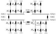
Fig. 2 is a schematic diagram of a wiring manner of a target substation after a line T is connected in embodiment 1 of the present invention.
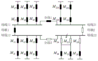
Fig. 3 is a schematic diagram of a connection mode of a target substation after bus fault isolation in embodiment 1 of the present invention.
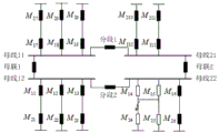
Fig. 4 is a schematic diagram of a connection mode of a target substation after fault isolation of an excess line or a servo line in embodiment 1 of the present invention.
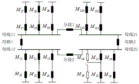
Fig. 5 is a schematic diagram of a connection mode of a target substation after the fault of the exceeding line is cleared in embodiment 1 of the present invention.
Fig. 6 is a schematic diagram of a connection mode of a target substation after a fault of a servo line is cleared in embodiment 1 of the present invention.
Detailed Description
The present invention will be described in further detail with reference to specific embodiments.
A method for improving the short-circuit current breaking capacity of a transformer substation in a T connection mode of a line sequentially comprises the following steps:
step A, screening out a target transformer substation from each 220KV transformer substation of the power grid, wherein the value obtained by subtracting the minimum branch line short-circuit current from the 220KV bus short-circuit current of the target transformer substation is larger than the rated breaking capacity of the circuit breaker, and the value obtained by subtracting any two branch line short-circuit currents from the 220KV bus short-circuit current of the target transformer substation is smaller than the rated breaking capacity of the circuit breaker;
and step B, carrying out T connection on the branch line of the target transformer substation and optimizing the running state of the breaker.
In the step B, the T-connection of the branch line of the target substation means: according to the wiring mode of a target transformer substation, a branch line with a value obtained by subtracting a short-circuit current from a bus short-circuit current and larger than the rated breaking capacity of a circuit breaker is used as an overproof line, a branch line which has little influence on power failure of the overproof line at the same time, is close to the layout position of the overproof line and can still normally run after the overproof line is stopped in the target transformer substation is used as a servo line, and the overproof line is T-connected to the servo line.
In step B, the optimizing the operating state of the circuit breaker means: and disconnecting the substation side circuit breaker where the overproof line is located.
The step A sequentially comprises the following steps:
a1, calculating the short-circuit current of a 220kV bus in each substation of the power grid in a mode of fully starting the power grid;
a2, selecting a transformer substation with the short-circuit current of the 220kV bus larger than the rated breaking capacity of the circuit breaker, and calculating the short-circuit current of a branch line of the transformer substation;
and A3, screening out a target substation from the substations in the step A2.
The method further comprises a fault isolation step, which is located after step B;
the fault isolation step is as follows:
when a bus connected with an overproof line or a servo line in a target substation breaks down, circuit breakers connected with the bus are tripped off to realize fault isolation;
when an overproof line or a servo line breaks down, the servo circuit breaker simultaneously trips the overproof line and the servo line, and meanwhile, the circuit breaker on the opposite side of the overproof line and the servo line transformer substation trips to realize fault isolation, wherein the servo circuit breaker is the circuit breaker on the transformer substation side where the servo line is located;
when other areas in the transformer substation have faults, the circuit breakers in the transformer substation realize fault isolation according to the opening and closing mode before the standard exceeding line and the servo line are not connected in a T mode.
The method further comprises a power restoration step, which is located after the fault isolation step;
the power supply recovery step comprises the following steps:
after the bus fault is cleared, all circuit breakers connected with the bus are switched on to recover the line power supply;
for the fault of the overproof line, the electrical connection between the servo circuit breaker and the overproof line is disconnected by the isolating switch, then the servo circuit breaker is switched on to recover power supply to the servo line, and the connection mode after the step B is completed is recovered after the fault is cleared;
and for the servo line fault, the electrical connection between the servo circuit breaker and the servo line is disconnected by the isolating switch, then the servo circuit breaker is switched on to recover power supply for the line exceeding the standard, and the wiring mode after the step B is completed is recovered after the fault is cleared.
The principle of the invention is illustrated as follows:
in the step B, when two overproof lines exist in the target substation at the same time, the two overproof lines can be subjected to T connection through calculation analysis and technical-economic comparison under the conditions that the reliability and the stability of the system are met and the requirement of the breaker breaking capacity of one line is met by the other line after the line is stopped.
The method can effectively realize fault isolation and power restoration after the fault, thereby ensuring the operation reliability of the transformer substation, and is suitable for various 220kV wiring modes (such as double-bus bypass, double-bus segmented bypass and the like).
GIS type transformer station: short for gas insulated substation. Most of electrical equipment in the transformer substation is directly or indirectly sealed in a pipe tree consisting of metal pipes and sleeves, and any switches, lines and wiring terminals cannot be seen from the outside. SF6 gas is used as an insulating medium in the pipeline, and all high-voltage electrical components are sealed in the grounding metal cylinder.
AIS-type substation: short for air insulated open-type substation. The electrical equipment in the transformer station is directly insulated by air, and the switch, the circuit and the wiring terminal can be seen from the outside, so that the transformation and the maintenance of related equipment are facilitated.
Example 1:
a method for improving the short-circuit current breaking capacity of a transformer substation in a T connection mode of a line takes a plurality of typical transformer substations in a certain province of China as objects (the short-circuit current condition of each transformer substation is shown in a table 1), and the method is sequentially carried out according to the following steps:
step 1, calculating short-circuit current of 220kV buses in each substation of a power grid in a mode of fully starting the power grid;
step 3, screening out a target transformer substation from each 220KV transformer substation of the power grid, wherein the value obtained by subtracting the minimum branch line short-circuit current from the 220KV bus short-circuit current of the target transformer substation is larger than the rated breaking capacity of the circuit breaker, and the value obtained by subtracting any two branch line short-circuit currents from the 220KV bus short-circuit current of the target transformer substation is smaller than the rated breaking capacity of the circuit breaker;
TABLE 1 typical 220kV short-circuit current situation (Unit: Qian' an) of several substations in a certain province
| Name of transformer station | Transformer substation A | Transformer substation B | Transformer substation C | Transformer substation D |
| Bus short circuit current | 42.3 | 51.2 | 53.1 | 57.6 |
| Outgoing line 1 branch short circuit current | 1.9 | 4.7 | 3.9 | |
| Outgoing 2-branch short-circuit current | 5.2 | 3.6 | 4.7 | |
| Outgoing line 3 branch short-circuit current | 3.4 | 10.2 | 5.6 | |
| Outgoing line 4 branch short-circuit current | 3.2 | 2.6 | 2.4 | |
| Outgoing line 5 branch short-circuit current | 9.2 | 1.9 | 10.3 | |
| Out-line 6 branch short-circuit current | 4.8 | 3.3 | 4.1 | |
| Outgoing line 7 branch short-circuit current | 2.9 | 10.1 | 3.4 | |
| Outgoing line 8 branch short-circuit current | 4.5 | 3.8 | 2.7 | |
| Outgoing line 9 branch short-circuit current | 9.2 | 4.3 | 10.4 | |
| Out-line 10 branch short-circuit current | 2.7 | 3.9 | 3.7 | |
| |
4.3 | 4.8 | 2.4 | |
| Outgoing line 12 branch short-circuit current | 4.0 |
As can be seen from Table 1: the value obtained by subtracting the short-circuit current of the outgoing line 5 branch from the short-circuit current of the 220kV bus of the transformer substation C is 50 kiloamperes greater than the rated breaking capacity of the circuit breaker, and the value obtained by subtracting the short-circuit current of any two outgoing line branches from the short-circuit current of the 220kV bus is 50 kiloamperes less than the rated breaking capacity of the circuit breaker, so that the transformer substation C is used as a target transformer substation (the wiring mode of the transformer substation is shown in figure 1);
step 4, according to the wiring mode of a target transformer substation, taking the outgoing line 4 with the value obtained by subtracting the short-circuit current of the bus from the short-circuit current of the bus as an overproof line, taking the outgoing line 5 which has little influence on power failure of the overproof line, is close to the layout position of the overproof line and can still normally run after the overproof line is shut down as a servo line (the circuit breaker M15 is a servo circuit breaker), carrying out T connection on the outgoing line 4 and the outgoing line 5, and simultaneously disconnecting the transformer substation side circuit breaker M14 where the outgoing line 4 is located to obtain the wiring mode shown in FIG. 2;
step 5, fault isolation, specifically comprising:
when the breaker bus-tie 2 breaks down, the section 2, the breakers M14, M15 and M16 are all disconnected to realize fault isolation, and the wiring mode of the transformer substation after the fault isolation is shown in FIG. 3;
and 6, power supply recovery, specifically comprising:
after the fault of the breaker bus coupler 2 is cleared, the breaker bus coupler 2 and the segment 2 are both closed to complete the charging of the bus, the breaker M15 is closed to recover the power supply to the outgoing line 4 and the outgoing line 5, the breaker M16 is closed to recover the power supply to the outgoing line 6, and the transformer substation wiring mode after the power supply is recovered is shown in fig. 2.
Example 2:
the difference from example 1 is that:
the step 5 is as follows: when the outgoing line 4 goes wrong, the breaker M14 only needs to cut off the sum of the short-circuit current of the bus and the branch short-circuit current of the outgoing line 4 and the outgoing line 5, the current is smaller than the rated breaking capacity of the breaker, the breaker M15 trips off the outgoing line 4 and the outgoing line 5, meanwhile, the breakers M24 and M25 on the opposite sides of the outgoing line 4 and the outgoing line 5 trip off, fault isolation is realized, and the wiring mode of a transformer substation after fault isolation is shown in FIG. 4;
the step 6 is as follows: the electrical connection between the circuit breaker M15 and the outgoing line 4 is disconnected through the disconnecting switch, then the circuit breaker M15 is switched on to restore power supply to the outgoing line 5, at the moment, the wiring mode of the transformer substation is as shown in FIG. 5, and the wiring mode after the step 4 is completed is restored after the fault of the outgoing line 4 is cleared.
Example 3:
the difference from example 1 is that:
the step 5 is as follows: when the outgoing line 5 has a fault, the circuit breaker M14 only needs to cut off the sum of the short-circuit current of the bus and the branch short-circuit current of the outgoing line 4 and the outgoing line 5, the current is smaller than the rated breaking capacity of the circuit breaker, the circuit breaker M15 trips off the outgoing line 4 and the outgoing line 5, meanwhile, the circuit breakers M24 and M25 on the opposite sides of the outgoing line 4 and the outgoing line 5 are also tripped, fault isolation is realized, and the wiring mode of a transformer substation after fault isolation is shown in FIG. 4;
the step 6 is as follows: and (3) the electrical connection between the circuit breaker M15 and the outgoing line 5 is disconnected through isolation, then the circuit breaker M15 is closed to restore power supply to the outgoing line 4, at the moment, the wiring mode of the transformer substation is as shown in figure 6, and the wiring mode after the step 4 is finished is restored after the fault of the outgoing line 5 is cleared.
Example 4:
the difference from example 1 is that:
the step 5 is as follows: other areas in the substation are out of order, and the circuit breaker M15 is kept unchanged to realize fault isolation;
step 6 is omitted.
Claims (5)
1. A method for improving the short-circuit current breaking capacity of a transformer substation in a T connection mode of a line is characterized by comprising the following steps:
the method comprises the following steps in sequence:
step A, screening out a target transformer substation from each 220KV transformer substation of the power grid, wherein the value obtained by subtracting the minimum branch line short-circuit current from the 220KV bus short-circuit current of the target transformer substation is larger than the rated breaking capacity of the circuit breaker, and the value obtained by subtracting any two branch line short-circuit currents from the 220KV bus short-circuit current of the target transformer substation is smaller than the rated breaking capacity of the circuit breaker;
and step B, performing T connection on the branch line of the target substation and optimizing the running state of the breaker, wherein the T connection on the branch line of the target substation is as follows: according to the wiring mode of a target transformer substation, a branch line with a value obtained by subtracting a short-circuit current from a bus short-circuit current and larger than the rated breaking capacity of a circuit breaker is used as an overproof line, a branch line which has little influence on power failure of the overproof line at the same time, is close to the layout position of the overproof line and can still normally run after the overproof line is stopped in the target transformer substation is used as a servo line, and the overproof line is T-connected to the servo line.
2. The method for improving the short-circuit current breaking capacity of the transformer substation in the T connection mode of the line according to claim 1, is characterized in that:
in step B, the optimizing the operating state of the circuit breaker means: and disconnecting the substation side circuit breaker where the overproof line is located.
3. The method for improving the short-circuit current breaking capacity of the transformer substation in the T connection mode of the line according to claim 1, is characterized in that:
the step A sequentially comprises the following steps:
a1, calculating the short-circuit current of a 220kV bus in each substation of the power grid in a mode of fully starting the power grid;
a2, selecting a transformer substation with the short-circuit current of the 220kV bus larger than the rated breaking capacity of the circuit breaker, and calculating the short-circuit current of each branch line;
and A3, screening out a target substation from the substations in the step A2.
4. The method for improving the short-circuit current breaking capacity of the transformer substation in the T connection mode of the line according to claim 1, is characterized in that:
the method further comprises a fault isolation step, which is located after step B;
the fault isolation step is as follows:
when a bus connected with an overproof line or a servo line in a target substation breaks down, circuit breakers connected with the bus are tripped off to realize fault isolation;
when an overproof line or a servo line breaks down, the servo circuit breaker simultaneously trips the overproof line and the servo line, and meanwhile, the circuit breaker on the opposite side of the overproof line and the servo line transformer substation trips to realize fault isolation, wherein the servo circuit breaker is the circuit breaker on the transformer substation side where the servo line is located;
when other areas in the transformer substation have faults, the circuit breakers in the transformer substation realize fault isolation according to the opening and closing mode before the standard exceeding line and the servo line are not connected in a T mode.
5. The method for improving the short-circuit current breaking capacity of the transformer substation in the T connection mode of the line according to claim 4, wherein the T connection mode comprises the following steps:
the method further comprises a power restoration step, which is located after the fault isolation step;
the power supply recovery step comprises the following steps:
after the bus fault is cleared, all circuit breakers connected with the bus are switched on to recover the line power supply;
for the fault of the overproof line, the electrical connection between the servo circuit breaker and the overproof line is disconnected by the isolating switch, then the servo circuit breaker is switched on to recover power supply to the servo line, and the connection mode after the step B is completed is recovered after the fault is cleared;
and for the servo line fault, the electrical connection between the servo circuit breaker and the servo line is disconnected by the isolating switch, then the servo circuit breaker is switched on to recover power supply for the line exceeding the standard, and the wiring mode after the step B is completed is recovered after the fault is cleared.
Priority Applications (1)
| Application Number | Priority Date | Filing Date | Title |
|---|---|---|---|
| CN201910456740.9A CN110277771B (en) | 2019-05-29 | 2019-05-29 | Method for improving short-circuit current breaking capacity of transformer substation in T connection mode |
Applications Claiming Priority (1)
| Application Number | Priority Date | Filing Date | Title |
|---|---|---|---|
| CN201910456740.9A CN110277771B (en) | 2019-05-29 | 2019-05-29 | Method for improving short-circuit current breaking capacity of transformer substation in T connection mode |
Publications (2)
| Publication Number | Publication Date |
|---|---|
| CN110277771A CN110277771A (en) | 2019-09-24 |
| CN110277771B true CN110277771B (en) | 2021-07-13 |
Family
ID=67959097
Family Applications (1)
| Application Number | Title | Priority Date | Filing Date |
|---|---|---|---|
| CN201910456740.9A Active CN110277771B (en) | 2019-05-29 | 2019-05-29 | Method for improving short-circuit current breaking capacity of transformer substation in T connection mode |
Country Status (1)
| Country | Link |
|---|---|
| CN (1) | CN110277771B (en) |
Families Citing this family (3)
| Publication number | Priority date | Publication date | Assignee | Title |
|---|---|---|---|---|
| CN111244907B (en) * | 2020-01-17 | 2022-09-09 | 中国电力科学研究院有限公司 | On-off time sequence control method and system of breaker in transformer substation |
| CN111262227A (en) * | 2020-01-17 | 2020-06-09 | 华北电力大学 | Method and device for regulating system topology to limit breaker on-off short-circuit current |
| CN112736871A (en) * | 2020-12-24 | 2021-04-30 | 国网浙江省电力有限公司电力科学研究院 | Method and system for finely checking short-circuit current of transformer substation of 220kV or below |
Citations (5)
| Publication number | Priority date | Publication date | Assignee | Title |
|---|---|---|---|---|
| CN107895940A (en) * | 2017-10-30 | 2018-04-10 | 国家电网公司 | A kind of method for limiting transformer station's 220KV short circuit currents |
| CN208637798U (en) * | 2018-08-28 | 2019-03-22 | 中国电力工程顾问集团西北电力设计院有限公司 | 500kV AIS deforms bridging line arragement construction |
| CN109599748A (en) * | 2018-10-31 | 2019-04-09 | 国网宁夏电力有限公司电力科学研究院 | Control method, device, storage medium and the processor of the short circuit current of substation |
| CN109687417A (en) * | 2019-01-28 | 2019-04-26 | 国电南瑞科技股份有限公司 | A kind of fault current limiter configuration method |
| CN208835751U (en) * | 2018-09-05 | 2019-05-07 | 广东电网有限责任公司 | One kind exempting from power failure T wiring line pole tower and T connects distribution system |
Family Cites Families (1)
| Publication number | Priority date | Publication date | Assignee | Title |
|---|---|---|---|---|
| JPH05122835A (en) * | 1991-10-28 | 1993-05-18 | Fuji Electric Co Ltd | Reverse power flow preventer for power system |
-
2019
- 2019-05-29 CN CN201910456740.9A patent/CN110277771B/en active Active
Patent Citations (5)
| Publication number | Priority date | Publication date | Assignee | Title |
|---|---|---|---|---|
| CN107895940A (en) * | 2017-10-30 | 2018-04-10 | 国家电网公司 | A kind of method for limiting transformer station's 220KV short circuit currents |
| CN208637798U (en) * | 2018-08-28 | 2019-03-22 | 中国电力工程顾问集团西北电力设计院有限公司 | 500kV AIS deforms bridging line arragement construction |
| CN208835751U (en) * | 2018-09-05 | 2019-05-07 | 广东电网有限责任公司 | One kind exempting from power failure T wiring line pole tower and T connects distribution system |
| CN109599748A (en) * | 2018-10-31 | 2019-04-09 | 国网宁夏电力有限公司电力科学研究院 | Control method, device, storage medium and the processor of the short circuit current of substation |
| CN109687417A (en) * | 2019-01-28 | 2019-04-26 | 国电南瑞科技股份有限公司 | A kind of fault current limiter configuration method |
Non-Patent Citations (1)
| Title |
|---|
| 王春玲.地区枢纽变电站智能化改造特殊运行方式安排.《宁夏电力》.2012,1-4页. * |
Also Published As
| Publication number | Publication date |
|---|---|
| CN110277771A (en) | 2019-09-24 |
Similar Documents
| Publication | Publication Date | Title |
|---|---|---|
| CN103208788B (en) | Intelligent Dynamic power network neutral point earthing method and the complete sets of equipment | |
| CN110277771B (en) | Method for improving short-circuit current breaking capacity of transformer substation in T connection mode | |
| CN104333118A (en) | Spare power automatic switching system with self-adaptive switching intermediate resistance grounding mode, and operation method thereof | |
| CN104767195A (en) | Small reactance value choose method during ultrahigh voltage autotransformer neutral point grounding in small reactance mode | |
| CN103368081A (en) | Main electrical connection of double-bus disconnecting link section | |
| CN107895940A (en) | A kind of method for limiting transformer station's 220KV short circuit currents | |
| CN111146773A (en) | Single-phase earth fault self-healing method for small current grounding system | |
| CN204190482U (en) | The spare power automatic switching system of middle resistance earthing mode self adaptation switching | |
| CN104471815A (en) | Bipolar high/low voltage converter station for series mtdc system | |
| Esmeraldo et al. | Circuit-breaker requirements for alternative configurations of a 500 kV transmission system | |
| CN109245291B (en) | Maintenance safety measure arrangement method for double-bus double-subsection power supply system of transformer substation | |
| CN207853185U (en) | The female simultaneous other system structure of substation | |
| CN111711176B (en) | Station domain protection method suitable for short-circuit current exceeding scene | |
| CN110676824B (en) | 110kV line disconnection protection method for collecting bus voltage of line load end | |
| CN111224384B (en) | Method for comparing line voltage vector difference on two sides of line and protecting line breakage by adopting loop closing and opening operation | |
| CN207459723U (en) | Spare phase transformer quickly puts into arrangement | |
| CN219937938U (en) | Single-phase grounding protection device for current collection system of offshore booster station | |
| CN219697303U (en) | Bus residual voltage temporary electricity holding device | |
| CN217882846U (en) | Neutral point grounding resistance automatic switching cabinet of high-voltage station service system | |
| CN217036738U (en) | Short-circuit protection configuration structure of high-voltage station transformer | |
| CN214589740U (en) | 110KV high-reliability user transformer substation | |
| CN211183418U (en) | 220KV bus differential system | |
| CN108281944B (en) | Differential protection connection system suitable for single bus sectionalized wiring and tripping logic method thereof | |
| CN111224385B (en) | Disconnection protection method for comparing voltage amplitude difference of two side wires of line and matching of spare power automatic switching | |
| CN112086867B (en) | 500kV typical series loop HGIS electrical interlocking control loop |
Legal Events
| Date | Code | Title | Description |
|---|---|---|---|
| PB01 | Publication | ||
| PB01 | Publication | ||
| SE01 | Entry into force of request for substantive examination | ||
| SE01 | Entry into force of request for substantive examination | ||
| GR01 | Patent grant | ||
| GR01 | Patent grant |