CN110262706B - Information processing apparatus, information processing method, and recording medium - Google Patents
Information processing apparatus, information processing method, and recording medium Download PDFInfo
- Publication number
- CN110262706B CN110262706B CN201910323652.1A CN201910323652A CN110262706B CN 110262706 B CN110262706 B CN 110262706B CN 201910323652 A CN201910323652 A CN 201910323652A CN 110262706 B CN110262706 B CN 110262706B
- Authority
- CN
- China
- Prior art keywords
- real
- virtual object
- type
- size
- image
- Prior art date
- Legal status (The legal status is an assumption and is not a legal conclusion. Google has not performed a legal analysis and makes no representation as to the accuracy of the status listed.)
- Active
Links
Images


Classifications
-
- G—PHYSICS
- G06—COMPUTING; CALCULATING OR COUNTING
- G06F—ELECTRIC DIGITAL DATA PROCESSING
- G06F3/00—Input arrangements for transferring data to be processed into a form capable of being handled by the computer; Output arrangements for transferring data from processing unit to output unit, e.g. interface arrangements
- G06F3/01—Input arrangements or combined input and output arrangements for interaction between user and computer
- G06F3/048—Interaction techniques based on graphical user interfaces [GUI]
- G06F3/0481—Interaction techniques based on graphical user interfaces [GUI] based on specific properties of the displayed interaction object or a metaphor-based environment, e.g. interaction with desktop elements like windows or icons, or assisted by a cursor's changing behaviour or appearance
- G06F3/04815—Interaction with a metaphor-based environment or interaction object displayed as three-dimensional, e.g. changing the user viewpoint with respect to the environment or object
-
- G—PHYSICS
- G06—COMPUTING; CALCULATING OR COUNTING
- G06F—ELECTRIC DIGITAL DATA PROCESSING
- G06F3/00—Input arrangements for transferring data to be processed into a form capable of being handled by the computer; Output arrangements for transferring data from processing unit to output unit, e.g. interface arrangements
- G06F3/01—Input arrangements or combined input and output arrangements for interaction between user and computer
- G06F3/048—Interaction techniques based on graphical user interfaces [GUI]
- G06F3/0481—Interaction techniques based on graphical user interfaces [GUI] based on specific properties of the displayed interaction object or a metaphor-based environment, e.g. interaction with desktop elements like windows or icons, or assisted by a cursor's changing behaviour or appearance
- G06F3/04812—Interaction techniques based on cursor appearance or behaviour, e.g. being affected by the presence of displayed objects
-
- G—PHYSICS
- G06—COMPUTING; CALCULATING OR COUNTING
- G06T—IMAGE DATA PROCESSING OR GENERATION, IN GENERAL
- G06T19/00—Manipulating 3D models or images for computer graphics
- G06T19/006—Mixed reality
-
- G—PHYSICS
- G06—COMPUTING; CALCULATING OR COUNTING
- G06T—IMAGE DATA PROCESSING OR GENERATION, IN GENERAL
- G06T19/00—Manipulating 3D models or images for computer graphics
- G06T19/20—Editing of 3D images, e.g. changing shapes or colours, aligning objects or positioning parts
-
- G—PHYSICS
- G06—COMPUTING; CALCULATING OR COUNTING
- G06T—IMAGE DATA PROCESSING OR GENERATION, IN GENERAL
- G06T7/00—Image analysis
- G06T7/70—Determining position or orientation of objects or cameras
- G06T7/73—Determining position or orientation of objects or cameras using feature-based methods
- G06T7/74—Determining position or orientation of objects or cameras using feature-based methods involving reference images or patches
-
- G—PHYSICS
- G06—COMPUTING; CALCULATING OR COUNTING
- G06F—ELECTRIC DIGITAL DATA PROCESSING
- G06F3/00—Input arrangements for transferring data to be processed into a form capable of being handled by the computer; Output arrangements for transferring data from processing unit to output unit, e.g. interface arrangements
- G06F3/01—Input arrangements or combined input and output arrangements for interaction between user and computer
- G06F3/011—Arrangements for interaction with the human body, e.g. for user immersion in virtual reality
-
- G—PHYSICS
- G06—COMPUTING; CALCULATING OR COUNTING
- G06F—ELECTRIC DIGITAL DATA PROCESSING
- G06F3/00—Input arrangements for transferring data to be processed into a form capable of being handled by the computer; Output arrangements for transferring data from processing unit to output unit, e.g. interface arrangements
- G06F3/01—Input arrangements or combined input and output arrangements for interaction between user and computer
- G06F3/017—Gesture based interaction, e.g. based on a set of recognized hand gestures
-
- G—PHYSICS
- G06—COMPUTING; CALCULATING OR COUNTING
- G06F—ELECTRIC DIGITAL DATA PROCESSING
- G06F3/00—Input arrangements for transferring data to be processed into a form capable of being handled by the computer; Output arrangements for transferring data from processing unit to output unit, e.g. interface arrangements
- G06F3/01—Input arrangements or combined input and output arrangements for interaction between user and computer
- G06F3/048—Interaction techniques based on graphical user interfaces [GUI]
- G06F3/0487—Interaction techniques based on graphical user interfaces [GUI] using specific features provided by the input device, e.g. functions controlled by the rotation of a mouse with dual sensing arrangements, or of the nature of the input device, e.g. tap gestures based on pressure sensed by a digitiser
- G06F3/0488—Interaction techniques based on graphical user interfaces [GUI] using specific features provided by the input device, e.g. functions controlled by the rotation of a mouse with dual sensing arrangements, or of the nature of the input device, e.g. tap gestures based on pressure sensed by a digitiser using a touch-screen or digitiser, e.g. input of commands through traced gestures
Abstract
The present disclosure provides an information processing apparatus, an information processing method, and a recording medium. The information processing apparatus includes circuitry configured to: acquiring an image of a real space; identifying a three-dimensional spatial structure of a real space based on the acquired image; calculating a size of a real object in real space based on the identified three-dimensional spatial structure; detecting one or more feature points of the real object in the acquired image and in the identified three-dimensional spatial structure; comparing the detected one or more feature points of the real object in the acquired image and in the identified three-dimensional spatial structure; selecting a virtual object to be displayed based on a size of the real object; and displaying the selected virtual object.
Description
The present application is a divisional application of an invention patent application having an application date of 2014/21, an application number of "201410108370.7", an invention name of "information processing apparatus, information processing method, and recording medium".
Cross Reference to Related Applications
This application claims priority from japanese priority patent application JP2013-072689, filed on 29/3/2013, the entire contents of which are incorporated herein by reference.
Background
The present disclosure relates to an information processing apparatus, an information processing method, and a recording medium.
A technique called Augmented Reality (AR) has recently attracted attention, which presents a user with a real space having additional information superimposed thereon. Various forms of virtual objects, such as text, icons, animations, etc., may be used to visualize the information presented to the user in AR technology. The placement of annotations on the AR space is typically performed based on the recognition of the three-dimensional structure of the real space displayed in the image.
A motion restoration structure (SfM) technique and a simultaneous localization and mapping (SLAM) technique are known as techniques for identifying a three-dimensional structure in a real space. In the SfM technique, a plurality of images are taken from different viewpoints, and from these images, a three-dimensional structure in a real space displayed in the images is recognized using parallax. SLAM technology is described in Andrew J.Davison, "Real-Time Simultaneous Localization and Mapping with a Single Camera", proceedings of the 9th IEEE International Conference on Computer Vision volume 2,2003, pages 1403-1410. JP 2009-237845A discloses a technique of identifying the three-dimensional position of a feature point selected for initialization in the SLAM technique by using the SfM technique.
Disclosure of Invention
The virtual object added to the real space may generally be controlled based on the size of the real object in the image. However, the size of the real object in the image may vary depending on the distance between the imaging section and the real object, and the like. Thus, it is hard to say that the size of the real object in the real space is sufficiently considered by only taking the size of the real object in the image into consideration.
In view of the foregoing, it is desirable in the present disclosure to provide a technique that makes it possible to control a virtual object in consideration of the size of a real object in a real space.
According to an embodiment of the present disclosure, there is provided an information processing apparatus including: an image acquisition section configured to acquire an image captured by the imaging section; and a display controller configured to cause a virtual object to be displayed according to a recognition result of a real object shown in the image. The display controller controls the virtual object based on a size of the real object in the real space.
According to another embodiment of the present disclosure, there is provided an information processing method including: acquiring an image photographed by an imaging section; causing a virtual object to be displayed according to a recognition result of a real object shown in an image; and controlling the virtual object based on the size of the real object in the real space.
According to another embodiment of the present disclosure, there is provided a non-transitory computer-readable recording medium having a program recorded thereon, the program being for causing a computer to function as an information processing apparatus including: an image acquisition section configured to acquire an image captured by the imaging section; and a display controller configured to cause a virtual object to be displayed according to a recognition result of a real object shown in the image. The display controller controls the virtual object based on a size of the real object in the real space.
According to one embodiment, an information processing apparatus includes circuitry configured to: acquiring an image of a real space; identifying a three-dimensional spatial structure of a real space based on the acquired image; calculating a size of a real object in a real space based on the identified three-dimensional spatial structure; detecting one or more feature points of the real object in the acquired image and in the identified three-dimensional spatial structure; comparing the detected one or more feature points of the real object in the acquired image and in the identified three-dimensional spatial structure; selecting a virtual object to be displayed based on a size of the real object; and displaying the selected virtual object.
According to one embodiment, an information processing method includes: acquiring an image of a real space; identifying a three-dimensional spatial structure of a real space based on the acquired image; calculating a size of a real object in real space based on the identified three-dimensional spatial structure; detecting one or more feature points of the real object in the acquired image and in the identified three-dimensional spatial structure; comparing the detected one or more feature points of the real object in the acquired image and in the identified three-dimensional spatial structure; selecting a virtual object to be displayed based on a size of the real object; and displaying the selected virtual object.
According to one embodiment, there is provided a non-transitory computer-readable recording medium having instructions stored thereon, which, when executed by a computer, cause the computer to perform operations comprising: acquiring an image of a real space; identifying a three-dimensional spatial structure of a real space based on the acquired image; calculating a size of a real object in real space based on the identified three-dimensional spatial structure; detecting one or more feature points of the real object in the acquired image and in the identified three-dimensional spatial structure; comparing the detected one or more feature points of the real object in the acquired image and in the identified three-dimensional spatial structure; selecting a virtual object to be displayed based on a size of the real object; and displaying the selected virtual object.
According to one or more of the embodiments of the present disclosure, the virtual object may be controlled in consideration of the size of the real object in the real space.
Drawings
Fig. 1 is a diagram showing an outline of an information processing apparatus according to a first embodiment of the present disclosure;
fig. 2 is a diagram showing a functional configuration example of an information processing apparatus according to a first embodiment of the present disclosure;
fig. 3 is a diagram showing an example of a technique of recognizing a real object from an image taken by an imaging section;
fig. 4 is a diagram showing a case where two types of real objects each having a different size in a real space are recognized;
FIG. 5 is a diagram showing an example of selecting a virtual object based on the size of a real object in real space;
fig. 6 is a diagram showing an example of controlling the motion of a virtual object based on the size of a real object in a real space;
fig. 7 is a diagram showing an example of controlling the size of a virtual object in an image based on the size of a real object in a real space;
fig. 8 is a flowchart showing an example of the flow of operations performed by the information processing apparatus according to the first embodiment of the present disclosure;
fig. 9 is a diagram showing a functional configuration example of an information processing apparatus according to a second embodiment of the present disclosure;
fig. 10 is a diagram showing an example of a technique for calculating the size of a real object in a real space;
fig. 11 is a diagram showing an example of a technique for calculating the size of a real object in a real space;
fig. 12 is a diagram showing an example of a technique for calculating the size of a real object in a real space;
fig. 13 is a diagram showing an example of controlling a virtual object based on a distance between a real object and a floor surface in a real space;
fig. 14 is a diagram showing an example of controlling a virtual object based on a relationship between the direction of gravity and the posture of a predetermined object;
fig. 15 is a diagram showing an example of controlling a virtual object based on a relationship between a posture of a predetermined object and a posture of a floor surface;
fig. 16 is a flowchart showing an example of the flow of operations performed by the information processing apparatus according to the second embodiment of the present disclosure; and
fig. 17 is a diagram showing an example of a hardware configuration of an information processing apparatus according to an embodiment of the present disclosure.
Detailed Description
Hereinafter, preferred embodiments of the present disclosure will be described in detail with reference to the accompanying drawings. Note that in the present specification and the drawings, structural elements having substantially the same function and structure are denoted by the same reference numerals, and repeated description of these structural elements is omitted.
Further, in the specification and the drawings, a plurality of structural elements having substantially the same function and structure are distinguished from each other by different letters or numbers following the same reference numeral in some cases. Note that, in the case where it is not necessary to distinguish a plurality of structural elements having the same function and structure from each other, only the same reference numerals are used to denote the plurality of structural elements.
Further, "detailed description" will be described in the following order.
1. Overview of information processing apparatus
2. First embodiment
2-1. Functional configuration example of information processing apparatus
2-2. Techniques for identifying real objects
2-3 examples of display control
2-4. Operation example of information processing apparatus
3. Second embodiment
3-1. Functional configuration example of information processing apparatus
3-2. Size of real object in real space
3-3 examples of display control
3-4. Operation example of information processing apparatus
4. Hardware configuration example
5. Summary of the invention
[ 1 ] overview of information processing apparatus
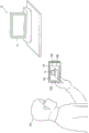
First, an outline of the information processing apparatus 10 according to the embodiment of the present disclosure will be described. Fig. 1 is a diagram of an outline of an information processing apparatus 10 according to an embodiment of the present disclosure. Referring to fig. 1, an information processing apparatus 10 held by a user Ua is shown. The information processing apparatus 10 includes an imaging section 120 directed to the real space E, an operation section 140, and a display section 160. The imaging section 120 generates an image by capturing the real space E.
In the example shown in fig. 1, the display section 160 displays an image Im captured by the imaging section 120. The user Ua can grasp the real space E by placing the viewpoint on the image Im displayed on the display unit 160. However, the image Im may not necessarily be displayed on the display section 160. For example, in the case where the display section 160 is a transmissive Head Mounted Display (HMD), the display section 160 does not display the image Im, and the user Ua may directly place the viewpoint on the real space E instead of the image Im.
Further, the real object a is displayed in the image Im. For example, when the real object a is recognized from the image Im, the information processing apparatus 10 places the virtual object in the AR space corresponding to the real space E based on the recognition result of the real object a. In this way, the user Ua can observe the virtual object placed in the AR space by the information processing apparatus 10 through the display section 160. The real object a may be recognized by the information processing apparatus 10, or may be recognized by a device (for example, a server) different from the information processing apparatus 10.
Here, the virtual object added to the real space E may be generally controlled based on the size of the real object a in the image Im. However, the size of the real object a in the image Im may vary according to the distance between the imaging section 120 and the real object a. Thus, it is hard to say that the size of the real object a in the real space E is sufficiently considered by only taking the size of the real object a in the image Im into consideration.
In view of the foregoing, the present disclosure provides a technique that makes it possible to control a virtual object in consideration of the size of a real object in a real space. In the first embodiment of the present disclosure, description is mainly made for a case where the size of the real object a in the real space E is known, and in the second embodiment of the present disclosure, description is mainly made for a case where the size of the real object a in the real space E is calculated.
Note that although the following description will be made as an example of a case where the information processing apparatus 10 is used as a camera-equipped smartphone, the information processing apparatus 10 may also be used as a device other than a smartphone. For example, the information processing apparatus 10 may be used as a video camera, a digital camera, a Personal Digital Assistant (PDA), a Personal Computer (PC), a mobile phone, a mobile music playback device, a mobile video processing device, a mobile game machine, a telescope, or binoculars.
Thus far, an outline of the information processing apparatus 10 of the embodiment of the present disclosure is described. Next, the first embodiment of the present disclosure and the second embodiment of the present disclosure will be described in the stated order. Note that the functions of the information processing apparatus 10 described in the first embodiment of the present disclosure and the information processing apparatus 10 described in the second embodiment of the present disclosure may be used in combination, or only some of the functions may be used in combination.
< 2 > first embodiment
Next, a first embodiment of the present disclosure will be described.
[2-1. Functional configuration example of information processing apparatus ]
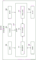
First, a functional configuration example of the information processing apparatus 10A according to the first embodiment of the present disclosure will be described. Fig. 2 is a diagram of a functional configuration example of the information processing apparatus 10A according to the first embodiment of the present disclosure. As shown in fig. 2, the information processing apparatus 10A includes a controller 110, an imaging section 120, a sensor section 130, an operation section 140, a memory 150, and a display section 160.
The controller 110 corresponds to, for example, a processor such as a Central Processing Unit (CPU) or a Digital Signal Processor (DSP). The controller 110 exhibits various functions possessed by the controller 110 by executing programs stored in the memory 150 or another storage medium. The controller 110 has functional blocks such as an image acquisition section 111, an image recognition section 113, and a display controller 115. The functions of the respective functional blocks will be described later.
The imaging section 120 is a camera module that takes an image Im. The imaging section 120 uses an image sensor such as a Charge Coupled Device (CCD) or a Complementary Metal Oxide Semiconductor (CMOS), and generates an image Im. The image Im generated by the imaging section 120 is output to the controller 110. Note that although the imaging section 120 is provided in an integrated manner with the information processing device 10A in the example shown in fig. 2, the imaging section 120 may also be provided separately from the information processing device 10A. For example, an imaging device electrically connected to the information processing apparatus 10A by wire or wirelessly may be used as the imaging section 120.
The sensor section 130 acquires sensor data. For example, the sensor part 130 includes a 3-axis acceleration sensor. The 3-axis acceleration sensor measures the gravitational acceleration applied to the imaging section 120, and generates sensor data (acceleration data) indicating the magnitude and direction of the three-dimensional gravitational acceleration. Further, the sensor part 130 may include a geomagnetic sensor. The geomagnetic sensor generates sensor data (geomagnetic data) indicating a geomagnetic direction of the imaging section 120 in the coordinate system. In addition, the sensor part 130 may further include a positioning sensor (e.g., a Global Positioning System (GPS) sensor). The positioning sensor generates sensor data (positioning data) indicating the longitude and latitude in the real space of the information processing apparatus 10A. Note that although the sensor section 130 is provided in an integrated manner with the information processing apparatus 10A in the example shown in fig. 2, the sensor section 130 may also be provided separately from the information processing apparatus 10A.
The operation section 140 detects an operation performed by the user and outputs the operation to the controller 110. In this specification, since it is assumed that the operation unit 140 is formed of a touch panel, the operation performed by the user corresponds to an operation of tapping the touch panel. However, the operation portion 140 may be formed of hardware (e.g., buttons) other than the touch panel. Note that although the operation section 140 is provided in an integrated manner with the information processing apparatus 10A in the example shown in fig. 2, the operation section 140 may also be provided separately from the information processing apparatus 10A.
The memory 150 stores a program for causing the controller 110 to operate using a recording medium such as a semiconductor memory or a hard disk. In addition, for example, the memory 150 may also store various types of data used by the program (e.g., various types of sensor data and virtual objects). Note that although the memory 150 is provided in an integrated manner with the information processing apparatus 10A in the example shown in fig. 2, the memory 150 may also be provided separately from the information processing apparatus 10A.
The display section 160 displays various types of information according to control performed by the display controller 115. For example, the display section 160 displays an image of the AR application generated by the information processing apparatus 10A. The display portion 160 is formed of, for example, a Liquid Crystal Display (LCD) or an organic Electroluminescence (EL) display device. Note that although the display section 160 is provided in an integrated manner with the information processing apparatus 10A in the example shown in fig. 2, the display section 160 may also be provided separately from the information processing apparatus 10A. For example, a display device electrically connected to the information processing apparatus 10A by wire or wirelessly may be used as the display section 160.
Heretofore, a functional configuration example of the information processing apparatus 10A according to the first embodiment of the present disclosure has been described.
[2-2. Technique for recognizing real object ]
First, a technique for identifying the real object a will be described. Fig. 3 is a diagram showing an example of a technique of recognizing a real object a from an image Im captured by the imaging section 120. Referring to fig. 3, in the image Im photographed by the imaging section 120, a real object a is displayed. Further, the real object a is recognized by the image recognition section 113, and the virtual object associated with the recognition result is placed in the AR space corresponding to the real space by the display controller 115.
In more detail, when the image recognition part 113 recognizes the position and posture of the real object a, the display controller 115 determines the position of the virtual object according to the position of the real object a, also determines the posture of the virtual object according to the posture of the real object a, and places the virtual object according to the determined position and posture. The relationship between the position of the real object a and the position of the virtual object may be determined in advance. Further, the relationship between the posture of the real object a and the posture of the virtual object may also be determined in advance.
For example, the image recognition part 113 checks a partial image included in the image Im against patches (patch) of corresponding feature points included in the feature data, and detects feature points included in the image Im. When the feature points belonging to the real object a are detected at high density in the region within the image Im, the image recognizing section 113 may recognize that the real object a is displayed in the region. The image recognizing section 113 may also recognize the position and the posture of the recognized real object a based on the positional relationship between the detected feature point and the three-dimensional shape data.
In the example shown in fig. 3, a block is provided on the floor plane, and a television apparatus serving as the real object a is placed on the block. However, the type of the real object a is not particularly limited. Referring to fig. 3, the size of the real object a in the real space E is represented by a size za, and the size of the real object a in the image Im is represented by a size Zai. Note that although the height of the real object a is set to the size of the real object a in the example shown in fig. 3, the size of the real object a may be the length of a portion other than the height of the real object a.
Here, when the user Ua holds the imaging section 120 on the real object a and the image recognition section 113 recognizes the real object a, the virtual object associated with the recognition result is placed in the AR space corresponding to the real space E by the display controller 115. In this case, in order to control the virtual object, the size Zai of the real object a in the image Im is generally considered without considering the size za of the real object a in the real space E.
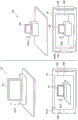
Fig. 4 is a diagram showing a case where two types of real objects each having a different size in a real space are recognized. Referring to fig. 4, a real object A1 exists in the real space E1, the size of the real object A1 in the real space E1 is represented by a size Zar1 and the image recognizing section 113 recognizes the size of the real object A1 in the image Im10 as the size Zai1.
On the other hand, the real object A2 exists in the real space E2, the size of the real object A2 in the real space E2 is represented by the size za 2 and the image recognizing section 113 recognizes the size of the real object A2 in the image Im20 as the size Zai2. For example, referring to fig. 4, the size za 1 of the real object A1 in the image Im10 is about the same as the size za 2 of the real object A2 in the image Im 20.
However, in reality, the distance between the imaging section 120 and the real object A1 is longer than the distance between the imaging section 120 and the real object A2. Instead, the size za 1 of the real object A1 in the real space E1 is larger than the size za 2 of the real object A2 in the real space E2. With this, the size of the real object a in the real space E cannot be directly grasped in general from only the size of the real object a in the image Im.
Thus, in the embodiment of the present disclosure, the image acquisition section 111 acquires the image Im captured by the imaging section 120, and the display controller 115 causes the virtual object to be displayed according to the recognition result of the real object a shown in the image Im. In this case, the display controller 115 controls the virtual object based on the size of the real object a in the real space E. According to such a configuration, it becomes possible to control the virtual object taking into consideration the size of the real object a in the real space E.
According to the first embodiment of the present disclosure, the display controller 115 can acquire the size of the real object a in the real space E. The size of the real object a in the real space E may be registered in the memory 150 in advance, may be input by the user through the operation section 140, and may be received by another device.
[2-3. Examples of display control ]
Here, various techniques may be adopted as a method for controlling the virtual object. Fig. 5 is a diagram showing an example of selecting a virtual object based on the size of the real object a in the real space E. First, with reference to fig. 5, an example of selecting a virtual object based on the size of the real object a in the real space E will be described.
Referring to fig. 5, in the same manner as the case shown in fig. 4, the size of the real object A1 in the real space E1 is a size Zar1. The display controller 115 may select the virtual object V11 having a size corresponding to the size za 1 of the real object A1 in the real space E1. For example, the display controller 115 may select the virtual object V11 in a case where the size za 1 of the real object A1 in the real space E1 exceeds a predetermined threshold. The virtual object V11 is not particularly limited.
On the other hand, referring to fig. 5, in the same manner as the case shown in fig. 4, the size of the real object A2 in the real space E2 is the size Zar2. The display controller 115 may select the virtual object V21 having a size corresponding to the size za 2 of the real object A2 in the real space E2. For example, the display controller 115 may select the virtual object V21 if the size za 2 of the real object A2 in the real space E2 is below a predetermined threshold. The virtual object V21 is not particularly limited.
Heretofore, although an example has been described in which a virtual object is selected based on the size of the real object a in the real space E, the display controller 115 may also control the display mode of the virtual object according to the size of the real object a in the real space E. For example, the display controller 115 may control the movement of the virtual object according to the size of the real object a in the real space.
Fig. 6 is a diagram showing an example of controlling the motion of a virtual object based on the size of the real object a in the real space E. Referring to fig. 6, an example of controlling the motion of the virtual object based on the size of the real object a in the real space E will be described.
Referring to fig. 6, in the same manner as the case shown in fig. 4, the size of the real object A1 in the real space E1 is a size Zar1. The display controller 115 may control the motion of the virtual object V12 based on the size za 1 of the real object A1 in the real space E1. For example, the display controller 115 may control such that the virtual object V12 has a predetermined first motion in a case where the size za 1 of the real object A1 in the real space E1 exceeds a predetermined threshold. The predetermined first motion is not particularly limited, and corresponds to a motion in which the virtual object V12 flies out from the real object A1 in the example shown in fig. 6.
On the other hand, referring to fig. 6, in the same manner as the case shown in fig. 4, the size of the real object A2 in the real space E2 is the size Zar2. The display controller 115 may control the motion of the virtual object V22 based on the size za 2 of the real object A2 in the real space E2. For example, the display controller 115 may control such that the virtual object V22 has a predetermined second motion in a case where the size za 2 of the real object A2 in the real space E2 is below a predetermined threshold. The predetermined second motion is not particularly limited, and corresponds to the motion in which the virtual object V22 is held within the real object A1 in the example shown in fig. 6.
Further, for example, the display controller 115 may also control the size of the virtual object in the image according to the size of the real object a in the real space E. For example, the display controller 115 may control the size of the virtual object in the image Im such that: the larger the size of the real object a in the real space E, the larger the size of the virtual object in the image Im.
Fig. 7 is a diagram showing an example of controlling the size of a virtual object in an image Im based on the size of a real object a in a real space E. First, with reference to fig. 7, an example of controlling the size of a virtual object in an image Im based on the size of a real object a in a real space E will be described.
Referring to fig. 7, in the same manner as the case shown in fig. 4, the size of the real object A1 in the real space E1 is a size Zar1. In the same manner as the case shown in fig. 4, the size of the real object A2 in the real space E2 is the size Zar2. Since the size za 1 of the real object A1 in the real space E1 is larger than the size za 2 of the real object A2 in the real space E2, the display controller 115 may render the size of the virtual object V13 in the image Im13 larger than the size of the virtual object V23 in the image Im 23.
Heretofore, an example of controlling the display mode of the virtual object based on the size of the real object a in the real space E has been described. Note that the display controller 115 is also capable of calculating the position of the real object a in the real space E based on the size of the real object a in the real space E. Specifically, the display controller 115 may calculate the position of the real object a in the real space E based on the position of the real object a in the image Im and the ratio of the size of the real object a in the real space E to the size of the real object a in the image Im.
The display controller 115 controls the virtual object based on the position of the real object a in the real space E thus calculated. Alternatively, the display controller 115 can also calculate the distance between the imaging section 120 and the real object a based on the position of the real object a in the real space E. Thus, the display controller 115 may also control the virtual object based on the distance between the imaging section 120 and the real object a. The technique for controlling the virtual object can be performed in the same manner as the case of: as described above, the virtual object is controlled based on the size of the real object a in the real space E.
[2-4. Operation example of information processing apparatus ]
Next, an example of an operation flow performed by the information processing apparatus 10A according to the first embodiment of the present disclosure will be described. Fig. 8 is a flowchart showing an example of the flow of operations performed by the information processing apparatus 10A according to the first embodiment of the present disclosure. First, the imaging section 120 takes an image, the image acquisition section 111 acquires the image, and then the image recognition section 113 recognizes the real object a from the image acquired by the image acquisition section 111 (S11). The display controller 115 determines a virtual object associated with the recognition result of the real object a (S12), and acquires the size of the real object a in the real space E (S13).
Next, the display controller 115 controls the virtual object based on the size of the real object a in the real space E (S14), and causes the virtual object to be displayed (S15). For example, in a case where the image recognition section 113 recognizes the position and posture of the real object a, the display controller 115 may cause the virtual object to be displayed at a position and posture corresponding to the recognized position and posture.
Heretofore, an example of the flow of operations performed by the information processing apparatus 10A according to the first embodiment of the present invention has been described.
<3. Second embodiment >
Next, a second embodiment of the present disclosure will be described. In the first embodiment of the present disclosure, a case where the size of the real object a in the real space E is known is described, whereas in the second embodiment of the present disclosure, a case where the size of the real object a in the real space E is calculated will be mainly described.
[3-1. Functional configuration example of information processing apparatus ]
Next, a functional configuration example of the information processing apparatus 10B according to the second embodiment of the present disclosure will be described. Fig. 9 is a diagram of a functional configuration example of an information processing apparatus 10B according to a second embodiment of the present disclosure. As shown in fig. 9, the information processing apparatus 10B includes a controller 110, an imaging section 120, a sensor section 130, an operation section 140, a memory 150, and a display section 160. The controller 110 has functional blocks such as an image acquisition section 111, a sensor data acquisition section 112, an image recognition section 113, an environment recognition section 114, and a display controller 115. The functions of the respective functional blocks will be described later.
[3-2. Size of real object in real space ]
First, a technique for calculating the position of the real object a in the real space E will be described. Fig. 10 to 12 are examples each showing a technique for calculating the size of the real object a in the real space E. Referring to fig. 10, an object B is disposed on a floor surface F. In fig. 10, the size of the object B in the real space E is represented by the size Zbr, and the size Zbr of the object B in the real space E is known. Thus, the size Zbr of the object B in the real space E may be registered in the memory 150 in advance, or may be input by the user Ua through the operation section 140.
Note that although a case where the object B is a package of a Digital Versatile Disc (DVD) will be mainly described, the object B may be an object other than the package of the DVD since the object B is only an example of a predetermined object. Further, although the case where the object B is disposed on the floor surface F will be mainly described below, the object B is not necessarily disposed on the floor surface F. Further, even in the case where the object B is arranged on the floor surface F, since the floor surface F is only an example of a predetermined plane, the object B may be arranged on a plane other than the floor surface F.
When the user Ua holds the imaging section 120 on the real space E, the imaging section 120 takes an image Im1, and the image recognizing section 113 recognizes the object B from the image Im 1. Specifically, the image recognition unit 113 recognizes the size Zbi of the object B in the image Im1, the position of the object B in the image Im1, and the posture Qbr of the object B. The display controller 115 calculates the position Pbr of the object B in the real space E based on the size Zbr of the object B in the real space E, the size Zbi of the object B in the image Im1, and the position Pbi of the object B in the image Im 1.
The display controller 115 can determine the position Pfr of the floor surface F in the real space E and the posture Qfr of the floor surface F based on the position Pbr of the object B in the real space E and the posture Qbr of the object B. For example, the display controller 115 can determine the position Pbr of the object B in the real space E as the position Pfr of the floor surface F in the real space F, and determine the posture Qbr of the object B as the posture Qfr of the bottom surface F.
Note that the user Ua is preferably notified of the fact that the position Pbr of the object B in the real space E has been determined. For example, the display controller 115 may cause the fact that the position Pbr of the object B in the real space E has been determined to be displayed. In the example shown in fig. 10, the fact that the position Pbr of the object B in the real space E has been determined is shown as a message M of "objects of known size have been recognized". However, the fact that the position Pbr of the object B in the real space E has been determined is not limited to such an example.
Then, there may be the following: the user Ua changes the position and posture of the imaging section 120 to cause the imaging section 120 to photograph the real object a. Accordingly, the display controller 115 may track the position and posture of the imaging section 120, and based on the tracking result, may track the position and posture of the object B. The display controller 115 may track the position and posture of the imaging section 120 with any technique, and as shown in fig. 11, for example, the display controller 115 may track the position and posture of the imaging section 120 based on the result of the environment recognition performed by the environment recognition section 114.
As the environment recognition by the environment recognition unit 114, calculation based on the SLAM technique can be used. According to the calculation based on the SLAM technique, the three-dimensional structure of the real space E shown by the image captured by the imaging section 120 and the position and orientation of the imaging section 120 can be dynamically recognized. For the initialization of the state variables in the SLAM technique, the position Pbr of the object B in the real space E and the posture Qbr of the object B may be used.
Next, the display controller 115 may calculate the position Par of the real object a in the real space E based on the recognition result of the object B recognized by the image recognition portion 113, the result of the environment recognition performed by the environment recognition portion 114, and the recognition result of the real object a recognized by the image recognition portion 113. Specifically, in the case where the image recognition part 113 recognizes the real object a, the display controller 115 may check the feature points recognized by the image recognition part 113 against the feature points obtained as the environment recognition result, and may calculate the position Par of the real object a in the real space E as a result of the matching check.
Further, the display controller 115 is also able to calculate the size za of the real object a in the real space E based on the thus calculated position Par of the real object a in the real space E, the size Zai of the real object a in the image Im3, and the position Pbr of the object B in the real space E.
Up to this point, the technique for calculating the position of the real object a in the real space E has been described.
[3-3. Examples of display control ]
Next, an example of controlling the display of the virtual object will be described. As described above, since the position and posture of the floor surface F are determined, the display controller 115 can control the virtual object based on the distance between the real object a and the floor surface F in the real space E. Fig. 13 is a diagram showing an example of controlling a virtual object based on the distance between the real object a and the floor surface F in the real space E.
Referring to fig. 13, the distance between the real object A1 and the floor surface F in the real space E1 is represented by a distance Har1. The display controller 115 is capable of calculating the distance Har1 between the real object A1 and the floor surface F in the real space E1 based on the position Par of the real object A1 in the real space E1 and the position Pfr and the posture Qfr of the floor surface F. The display controller 115 can adjust the virtual object V14 having a size corresponding to the size of the real object A1 in the real space E1 according to the distance Har1.
For example, the display controller 115 can move the position of the virtual object V14 having a size corresponding to the size of the real object A1 in the real space E1 near the floor plane F by the distance Har1 in the real space E1. In this way, as shown in fig. 13, the display controller 115 can normally perform the placement of the virtual object V14 in a normal state in which the virtual object V14 appears in contact with the floor surface F.
Further, referring to fig. 13, the distance between the real object A2 and the floor surface F in the real space E1 is represented by a distance Har2. The display controller 115 can calculate the distance Har2 between the real object A2 and the floor surface F in the real space E2 based on the position Par2 of the real object A2 in the real space E2 and the position Pfr and the posture Qfr of the floor surface F. The display controller 115 can adjust the virtual object V24 having a size corresponding to the size of the real object A2 in the real space E2 according to the distance Har2.
For example, the display controller 115 can move the position of the virtual object V24 having a size corresponding to the size of the real object A2 in the real space E2 by the distance Har2 near the floor plane F in the real space E2. In this way, as shown in fig. 13, the display controller 115 can normally perform the placement of the virtual object V24 in a normal state in which the virtual object V24 appears in contact with the floor surface F.
Note that, in the example shown in fig. 13, the size of the virtual object V14 in the image Im14 is controlled in accordance with the size of the real object A1 in the real space E1. In the same manner, in the example shown in fig. 13, the size of the virtual object V24 in the image Im24 is controlled in accordance with the size of the real object A2 in the real space E2. If the virtual object is placed in the AR space in real size, the user Ua can be made to feel the size of the virtual object more realistically.
Thus, to place the virtual object in the AR space at the real size, the display controller 115 may control the virtual object based on the size of the real object a in the real space E and known data about the real size of the virtual object. For example, the display controller 15 may determine the ratio of the size of the virtual object in the image to the size of the real object a in the image based on the relationship between the size of the real object a in the real space E and known data on the real size of the virtual object.
For example, the display controller 115 may control such that the ratio of the known data relating to the real size of the virtual object to the size of the real object a in the real space E is equal to the ratio of the size of the virtual object in the image to the size of the real object a in the image. In this way, since the virtual object V14 placed in the real space E1 and the virtual object V24 placed in the real space E2 each have the real size of the virtual object, this enables the user Ua to more realistically sense the size of the virtual object.
Further, the display controller 115 may control the virtual object based on the tilt of the object. For example, in a case where the sensor section 130 is capable of detecting the gravity direction G, the display controller 115 may control the virtual object based on the relationship between the gravity direction G detected by the sensor section 130 and the object. For example, the gravity direction G may be detected by an acceleration sensor or the like. The gravity direction G detected by the sensor unit 130 can be acquired by the sensor data acquisition unit 112.
Fig. 14 is a diagram of an example of controlling a virtual object based on a relationship between the direction of gravity G and the posture of the object B. The display controller 115 can control the virtual object based on the relationship between the gravity direction G and the posture of the object B.
Referring to fig. 14, in the real space E30, an object B having a posture matching the gravity direction G is arranged on the floor plane F. In such a case, the virtual object V30 associated with the recognition result of the real object a may be placed on the floor surface F. On the other hand, in the real space E31, the object B having a posture not matching the gravity direction G is arranged on the floor plane F. In such a case, the virtual object V31 associated with the recognition result of the real object a may be placed on the floor surface F.
In fig. 14, the display controller 115 places the virtual object V30 indicating a state in which the posture of the virtual object V30 remains stationary with respect to the floor surface F in the AR space in a case where the posture of the object B matches the gravity direction G. On the other hand, the display controller 115 places the virtual object V31 indicating a state in which the virtual object V31 is slid on the floor surface F in the AR space in a case where the posture of the object B does not match the direction of gravity G. However, the virtual object V30 and the virtual object V31 may each be controlled in any manner.
Fig. 15 is a diagram of an example of controlling a virtual object based on a relationship between the direction of gravity G and the posture of the real object a. The display controller 115 is also able to control the virtual object based on the relationship between the direction of gravity G and the posture of the real object a.
Referring to fig. 15, in the real space E30, a real object a having a matching gravity direction G is arranged on the floor plane F. In such a case, the virtual object V30 associated with the recognition result of the real object a may be placed on the floor surface F. On the other hand, in the real space E32, the real object a having a posture not matching the gravity direction G is arranged on the floor plane F. In such a case, the virtual object V32 associated with the recognition result of the real object a may be placed on the floor surface F.
In fig. 15, in a case where the posture of the real object a matches the gravity direction G, the display controller 115 places the virtual object V30 in the AR space in a state indicating that the posture of the virtual object V30 remains stationary with respect to the floor surface F. On the other hand, in a case where the posture of the real object a does not match the gravity direction G, the display controller 115 places the virtual object V32 indicating the state in which the virtual object V32 is sliding on the floor surface F in the AR space. However, the virtual object V30 and the virtual object V32 may each be controlled in any manner.
Further, the display controller 115 may control the virtual object based on the relationship between the posture of the floor surface F and the posture of the real object a. In the same manner as in the case shown in fig. 15, the display controller 115 places the virtual object 30 indicating a state in which the posture of the virtual object V30 remains stationary with respect to the floor plane in the AR space in a case where the posture of the real object a matches the posture of the floor plane F. On the other hand, the display controller 115 places the virtual object V32 indicating the state in which the virtual object V32 is sliding on the floor surface F in the AR space in a case where the posture of the real object a does not match the posture of the floor plane F. However, the virtual object V30 and the virtual object V32 may each be controlled in any manner.
[3-4. Operation example of information processing apparatus ]
Next, an example of the flow of operations performed by the information processing apparatus 10B according to the second embodiment of the present disclosure will be described. Fig. 16 is a flowchart showing an example of the flow of operations performed by the information processing apparatus 10B according to the second embodiment of the present disclosure. First, when the imaging section 120 captures an image and the image acquisition section 111 acquires the image, the image recognition section 113 recognizes the object B from the image acquired by the image acquisition section 111 (S21). The display controller 115 determines the position Pbr of the object B in the real space E (S22), and the environment recognition portion 114 starts environment recognition (S23).
Next, the image recognizing unit 113 recognizes the real object a from the image acquired by the image acquiring unit 111 (S24). The display controller 115 determines a virtual object associated with the recognition result of the real object a (S25), and calculates a position Par of the real object a in the real space E (S26). Further, the display controller 115 calculates the size Zar of the real object a in the real space E (S27), controls the virtual object based on the size Zar of the real object a in the real space E (S28), and causes the virtual object to be displayed (S29).
Heretofore, an example of the flow of operations performed by the information processing apparatus 10B according to the second embodiment of the present invention has been described.
< <4. Hardware configuration example >
Next, a hardware configuration example of the information processing apparatus 10 according to the embodiment of the present disclosure will be described. Fig. 17 is a diagram showing an example of the hardware configuration of the information processing apparatus 10 according to the embodiment of the present disclosure. It should be noted that the hardware configuration example shown in fig. 17 is merely an example of the hardware configuration of the information processing apparatus 10. Therefore, the hardware configuration of the information processing apparatus 10 is not limited to the example shown in fig. 17.
As shown in fig. 17, the information processing apparatus 10 includes a Central Processing Unit (CPU) 801, a Read Only Memory (ROM) 802, a Random Access Memory (RAM) 803, a sensor 804, an input device 808, an output device 810, a storage device 811, a driver 812, an imaging device 813, and a communication device 815.
The CPU 801 functions as an algorithm processing unit and a control unit, and controls the entire operation of the information processing apparatus 10 according to various programs. Further, the CPU 801 may also be a microprocessor. The ROM 802 stores programs, calculation parameters, and the like used by the CPU 801. The RAM 803 temporarily stores programs for execution in the CPU 801, parameters that change appropriately during execution, and the like. The CPU 801, the ROM 802, and the RAM 803 are connected to each other by a host bus configured according to a CPU bus or the like.
The sensor 804 includes various types of detection sensors such as a terminal state detection sensor for detecting the state of the information processing apparatus 10 and its peripheral circuits, and the like. Examples of sensors 804 include a tilt sensor, an acceleration sensor, a direction sensor, a temperature sensor, a humidity sensor, and a light intensity sensor. The detection information obtained by the sensor 804 is sent to the CPU 801. In this way, the CPU 801 can know the state (inclination, acceleration, direction, temperature, humidity, light intensity, and the like) of the information processing apparatus 10.
The input device 808 is configured by, for example, an input section for a user to input information, such as a mouse, a keyboard, a touch panel, buttons, a microphone, switches, a lever, and the like, and an input control circuit that generates an input signal based on an input by the user and outputs the generated input signal to the CPU 801. The user of the information processing apparatus 10 can input various data to the information processing apparatus 10, and can instruct the information processing apparatus 10 to perform a processing operation by operating the input device 808.
The output device 810 may include, for example, a display device such as a Liquid Crystal Display (LCD) device, an Organic Light Emitting Diode (OLED) device, and a lamp. In addition, the input device 810 includes an audio output device such as a speaker and an earphone. For example, the display devices each display a captured image, a generated image, and the like. On the other hand, the audio output devices each convert audio data or the like into audio and output the audio.
The storage 811 is a means for storing data, which is configured as an example of a memory of the information processing apparatus 10. The storage device 811 may include, for example, a storage medium, a recording device for recording data in the storage medium, a reading device for reading out data from the storage medium, and a deleting device for deleting data recorded in the storage medium. The storage device 811 stores programs executed by the CPU 801 and various data.
The drive 812 is a reader/writer of a storage medium, and is built in the information processing apparatus 10 or externally attached to the information processing apparatus 10. The drive 812 reads out information recorded in a removable storage medium 71 (such as a magnetic disk, an optical disk, a magneto-optical disk, or a semiconductor memory) mounted to the drive 812, and outputs the information to the RAM 803. The drive 812 may also write information to the removable storage medium 71.
The imaging apparatus 813 includes an imaging optical system such as a photographing lens and a zoom lens for condensing light, and a signal conversion device such as a Charge Coupled Device (CCD) or a Complementary Metal Oxide Semiconductor (CMOS). The imaging optical system collects light emitted from the object and forms an image of the object at the signal conversion section, and the signal conversion device converts the formed image of the object into an electrical image signal.
The communication means 815 is a communication interface configured by, for example, a communication means for establishing a connection with a network. Further, the communication device 815 may be a wireless Local Area Network (LAN) -enabled communication device, a Long Term Evolution (LTE) -enabled communication device, or a wired communication device for conducting wired communications. The communication device 815 may communicate with other devices using the network 30.
Heretofore, a hardware configuration example of the information processing apparatus 10 according to the embodiment of the present disclosure is described.
<5. Summary >, a pharmaceutical composition comprising the same
As described above, according to an embodiment of the present disclosure, there is provided an information processing apparatus 10 including: an image acquisition section 111 configured to acquire an image Im captured by the imaging section 120; and a display controller 115 configured to cause a virtual object to be displayed according to a recognition result of the real object a shown in the image Im, wherein the display controller 115 controls the virtual object based on a size za of the real object a in the real space E. According to such a configuration, it becomes possible to control the virtual object in consideration of the size of the real object a in the real space E.
Those skilled in the art will appreciate that various modifications, combinations, sub-combinations, and substitutions are possible, depending on design requirements and other factors, provided they are within the scope of the appended claims and their equivalents.
For example, the display unit may be a Head Mounted Display (HMD). For example, in the case where a non-transmissive HMD is used as the display portion, the image does not have to be displayed on the display portion. In such a case, the display portion may superimpose the virtual object on the real space instead of the image.
Further, in the embodiment of the present disclosure, an example in which the result of controlling the virtual object by the information processing apparatus 10 is reflected in the AR space of the information processing apparatus 10 is mainly described. However, for example, in a case where a single AR space is shared between the information processing apparatus 10 and other devices, the result of controlling the virtual object by the information processing apparatus 10 may be reflected in the AR space of the other devices communicating with the information processing apparatus 10.
Further, it is also possible to create a program for causing hardware such as a CPU, a ROM, and a RAM built in a computer to sufficiently exhibit the same functions as those of the corresponding structure of the information processing apparatus 10 described above. Further, a non-transitory computer-readable recording medium having the program recorded thereon is also provided.
Further, the present technology can also be configured as follows.
(1) An information processing apparatus comprising:
an image acquisition section configured to acquire an image captured by the imaging section; and
a display controller configured to cause a virtual object to be displayed according to a recognition result of a real object shown in the image,
wherein the display controller controls the virtual object based on a size of the real object in real space.
(2) The information processing apparatus according to (1),
wherein the display controller calculates the size of the real object in the real space based on the position of a predetermined object in the real space, the size of the real object in the image, and the position of the real object in the real space, the position of the predetermined object in the real space being determined according to known data about the size of the predetermined object in the real space, the size of the predetermined object in the image, and the position of the predetermined object in the image.
(3) The information processing apparatus according to (2),
wherein the display controller controls the virtual object based on a distance between the real object and a predetermined plane in the real space.
(4) The information processing apparatus according to (2),
wherein the display controller controls the virtual object based on a relationship between a direction of gravity and a posture of the predetermined object.
(5) The information processing apparatus according to (2),
wherein the display controller controls the virtual object based on a relationship between a direction of gravity and a posture of the real object.
(6) The information processing apparatus according to (2),
wherein the display controller controls the virtual object based on a relationship between a gesture of a predetermined plane and a gesture of the real object.
(7) The information processing apparatus according to any one of (3) to (6),
wherein, when the predetermined object is set on the predetermined plane, the display controller determines the position and posture of the predetermined plane in the real space based on the position and posture of the predetermined object in the real space.
(8) The information processing apparatus according to (2),
wherein the display controller causes the fact that the position of the predetermined object in the real space has been determined to be displayed.
(9) The information processing apparatus according to (1),
wherein the display controller controls the virtual object based on a position of the real object in the real space.
(10) The information processing apparatus according to (1),
wherein the display controller controls the virtual object based on a distance between the imaging part and the real object.
(11) The information processing apparatus according to any one of (1) to (10),
wherein the display controller controls the virtual object based on a size of the real object in the real space and known data relating to a real size of the virtual object.
(12) The information processing apparatus according to (11),
wherein the display controller determines a ratio of the size of the virtual object in the image to the size of the real object in the image based on a relationship between the size of the real object in the real space and the known data relating to the real size of the virtual object.
(13) The information processing apparatus according to (1),
wherein the display controller acquires a size of the real object in the real space.
(14) The information processing apparatus according to (2),
wherein the display controller calculates a position of the real object in the real space based on a recognition result of the predetermined object, a result of the environment recognition, and a recognition result of the real object.
(15) The information processing apparatus according to any one of (1) to (14),
wherein the display controller selects the virtual object based on a size of the real object in the real space.
(16) The information processing apparatus according to any one of (1) to (14),
wherein the display controller controls a display mode of the virtual object according to a size of the real object in the real space.
(17) The information processing apparatus according to (16),
wherein the display controller controls the motion of the virtual object according to the size of the real object in the real space.
(18) The information processing apparatus according to (16),
wherein the display controller controls a size of the virtual object in the image according to a size of the real object in the real space.
(19) An information processing method comprising:
acquiring an image captured by an imaging section;
causing a virtual object to be displayed according to a recognition result of a real object shown in the image; and
controlling the virtual object based on a size of the real object in real space.
(20) A non-transitory computer-readable recording medium having recorded thereon a program for causing a computer to function as an information processing apparatus, the information processing apparatus comprising:
an image acquisition section configured to acquire an image captured by the imaging section; and
a display controller configured to cause a virtual object to be displayed according to a recognition result of a real object shown in the image,
wherein the display controller controls the virtual object based on a size of the real object in a real space.
Claims (5)
1. An information processing apparatus comprising:
circuitry configured to:
acquiring an image of a real space;
identifying a three-dimensional spatial structure of the real space based on the acquired image;
calculating a size of a real object in the real space based on the identified three-dimensional spatial structure;
selecting at least one of a first type of virtual object or a second type of virtual object based on a size of the real object; and
the selected virtual object is displayed and,
wherein the first type of virtual object is indicative of a first image of a first type of real object and the second type of virtual object is indicative of a second image of a second type of real object,
wherein the first type of real object and the second type of real object have different sizes in the real space,
wherein the first type of virtual object and the second type of virtual object have different virtual object motion patterns,
wherein, in case the size of the real object exceeds a predetermined threshold, the first type of virtual object is selected and has a first motion corresponding to a motion of the first type of virtual object flying off the real object, and
wherein, in case the size of the real object is below the predetermined threshold, the second type virtual object is selected and has a second motion corresponding to a motion in which the second type virtual object remains within the real object.
2. The information processing apparatus of claim 1, wherein the circuitry is further configured to:
detecting one or more feature points of the real object in the acquired image and in the identified three-dimensional spatial structure; and
comparing the detected one or more feature points of the real object in the acquired image and in the identified three-dimensional spatial structure.
3. The information processing apparatus of claim 1, wherein the circuitry is further configured to identify a three-dimensional spatial structure of the real space based on a simultaneous localization and mapping technique.
4. An information processing method, comprising:
acquiring an image of a real space;
identifying a three-dimensional spatial structure of the real space based on the acquired image;
calculating a size of a real object in the real space based on the identified three-dimensional spatial structure;
selecting at least one of a first type of virtual object or a second type of virtual object based on a size of the real object; and
the selected virtual object is displayed and,
wherein the first type of virtual object is indicative of a first image of a first type of real object and the second type of virtual object is indicative of a second image of a second type of real object,
wherein the first type of real object and the second type of real object have different sizes in the real space,
wherein the first type of virtual object and the second type of virtual object have different virtual object motion patterns,
wherein, in case the size of the real object exceeds a predetermined threshold, the first type of virtual object is selected and has a first motion corresponding to the motion of the first type of virtual object flying off the real object, and
wherein, in case the size of the real object is below the predetermined threshold, the second type virtual object is selected and has a second motion corresponding to a motion in which the second type virtual object remains within the real object.
5. A non-transitory computer-readable recording medium having instructions stored thereon, which, when executed by a computer, cause the computer to perform operations comprising:
acquiring an image of a real space;
identifying a three-dimensional spatial structure of the real space based on the acquired image;
calculating a size of a real object in the real space based on the identified three-dimensional spatial structure;
selecting at least one of a first type of virtual object or a second type of virtual object based on a size of the real object; and
the selected virtual object is displayed and,
wherein the first type of virtual object is indicative of a first image of a first type of real object and the second type of virtual object is indicative of a second image of a second type of real object,
wherein the first type of real object and the second type of real object have different sizes in the real space,
wherein the first type of virtual object and the second type of virtual object have different virtual object motion patterns,
wherein, in case the size of the real object exceeds a predetermined threshold, the first type of virtual object is selected and has a first motion corresponding to the motion of the first type of virtual object flying off the real object, and
wherein, in case the size of the real object is below the predetermined threshold, the second type virtual object is selected and has a second motion corresponding to the motion of the second type virtual object remaining within the real object.
Applications Claiming Priority (3)
| Application Number | Priority Date | Filing Date | Title |
|---|---|---|---|
| JP2013072689A JP5790692B2 (en) | 2013-03-29 | 2013-03-29 | Information processing apparatus, information processing method, and recording medium |
| JP2013-072689 | 2013-03-29 | ||
| CN201410108370.7A CN104077024A (en) | 2013-03-29 | 2014-03-21 | Information processing apparatus, information processing method, and recording medium |
Related Parent Applications (1)
| Application Number | Title | Priority Date | Filing Date |
|---|---|---|---|
| CN201410108370.7A Division CN104077024A (en) | 2013-03-29 | 2014-03-21 | Information processing apparatus, information processing method, and recording medium |
Publications (2)
| Publication Number | Publication Date |
|---|---|
| CN110262706A CN110262706A (en) | 2019-09-20 |
| CN110262706B true CN110262706B (en) | 2023-03-10 |
Family
ID=51598325
Family Applications (2)
| Application Number | Title | Priority Date | Filing Date |
|---|---|---|---|
| CN201910323652.1A Active CN110262706B (en) | 2013-03-29 | 2014-03-21 | Information processing apparatus, information processing method, and recording medium |
| CN201410108370.7A Pending CN104077024A (en) | 2013-03-29 | 2014-03-21 | Information processing apparatus, information processing method, and recording medium |
Family Applications After (1)
| Application Number | Title | Priority Date | Filing Date |
|---|---|---|---|
| CN201410108370.7A Pending CN104077024A (en) | 2013-03-29 | 2014-03-21 | Information processing apparatus, information processing method, and recording medium |
Country Status (3)
| Country | Link |
|---|---|
| US (3) | US9665982B2 (en) |
| JP (1) | JP5790692B2 (en) |
| CN (2) | CN110262706B (en) |
Families Citing this family (22)
| Publication number | Priority date | Publication date | Assignee | Title |
|---|---|---|---|---|
| JP2014191718A (en) | 2013-03-28 | 2014-10-06 | Sony Corp | Display control device, display control method, and recording medium |
| JP5790692B2 (en) * | 2013-03-29 | 2015-10-07 | ソニー株式会社 | Information processing apparatus, information processing method, and recording medium |
| US10262462B2 (en) | 2014-04-18 | 2019-04-16 | Magic Leap, Inc. | Systems and methods for augmented and virtual reality |
| JP6596883B2 (en) | 2015-03-31 | 2019-10-30 | ソニー株式会社 | Head mounted display, head mounted display control method, and computer program |
| CN108603749B (en) * | 2016-02-02 | 2021-12-21 | 索尼公司 | Information processing apparatus, information processing method, and recording medium |
| CN106203300A (en) * | 2016-06-30 | 2016-12-07 | 北京小米移动软件有限公司 | Content item display packing and device |
| CN106952349A (en) * | 2017-03-29 | 2017-07-14 | 联想(北京)有限公司 | A kind of display control method, device and electronic equipment |
| EP3413166B1 (en) * | 2017-06-06 | 2023-06-21 | Nokia Technologies Oy | Rendering mediated reality content |
| US10818093B2 (en) * | 2018-05-25 | 2020-10-27 | Tiff's Treats Holdings, Inc. | Apparatus, method, and system for presentation of multimedia content including augmented reality content |
| US10890653B2 (en) | 2018-08-22 | 2021-01-12 | Google Llc | Radar-based gesture enhancement for voice interfaces |
| US10770035B2 (en) | 2018-08-22 | 2020-09-08 | Google Llc | Smartphone-based radar system for facilitating awareness of user presence and orientation |
| US10698603B2 (en) * | 2018-08-24 | 2020-06-30 | Google Llc | Smartphone-based radar system facilitating ease and accuracy of user interactions with displayed objects in an augmented-reality interface |
| US10788880B2 (en) | 2018-10-22 | 2020-09-29 | Google Llc | Smartphone-based radar system for determining user intention in a lower-power mode |
| CA3104444A1 (en) * | 2018-11-08 | 2020-05-14 | Rovi Guides, Inc. | Methods and systems for augmenting visual content |
| US10761611B2 (en) | 2018-11-13 | 2020-09-01 | Google Llc | Radar-image shaper for radar-based applications |
| KR102581146B1 (en) * | 2018-11-23 | 2023-09-21 | 삼성전자주식회사 | Display apparatus and control method thereof |
| US11468611B1 (en) * | 2019-05-16 | 2022-10-11 | Apple Inc. | Method and device for supplementing a virtual environment |
| US20210097731A1 (en) * | 2019-09-26 | 2021-04-01 | Apple Inc. | Presenting environment based on physical dimension |
| WO2021117415A1 (en) | 2019-12-10 | 2021-06-17 | ソニーグループ株式会社 | Information processing system, information processing method, and program |
| CN112308980A (en) * | 2020-10-30 | 2021-02-02 | 脸萌有限公司 | Augmented reality interactive display method and equipment |
| CN112988007B (en) * | 2021-03-12 | 2022-09-09 | 深圳市慧鲤科技有限公司 | Three-dimensional material interaction method and device |
| JP7354186B2 (en) * | 2021-06-18 | 2023-10-02 | ヤフー株式会社 | Display control device, display control method, and display control program |
Citations (5)
| Publication number | Priority date | Publication date | Assignee | Title |
|---|---|---|---|---|
| CN101379369A (en) * | 2006-01-09 | 2009-03-04 | 诺基亚公司 | Displaying network objects in mobile devices based on geolocation |
| CN102194254A (en) * | 2010-03-04 | 2011-09-21 | 索尼公司 | Information processing device, information processing method, and program |
| CN102708355A (en) * | 2011-02-15 | 2012-10-03 | 索尼公司 | Information processing device, authoring method, and program |
| CN102792338A (en) * | 2009-12-07 | 2012-11-21 | 索尼公司 | Information processing device, information processing method, and program |
| CN102866825A (en) * | 2011-06-21 | 2013-01-09 | 索尼公司 | Display control apparatus, display control method and program |
Family Cites Families (23)
| Publication number | Priority date | Publication date | Assignee | Title |
|---|---|---|---|---|
| JP3639475B2 (en) * | 1999-10-04 | 2005-04-20 | シャープ株式会社 | 3D model generation apparatus, 3D model generation method, and recording medium on which 3D model generation program is recorded |
| JP2004046326A (en) * | 2002-07-09 | 2004-02-12 | Dainippon Screen Mfg Co Ltd | Device and method for displaying picture and program |
| JP4085918B2 (en) * | 2003-07-18 | 2008-05-14 | ソニー株式会社 | 3D model processing apparatus, 3D model processing method, and computer program |
| US7307433B2 (en) * | 2004-04-21 | 2007-12-11 | Formfactor, Inc. | Intelligent probe card architecture |
| JP3841806B2 (en) * | 2004-09-01 | 2006-11-08 | 株式会社ソニー・コンピュータエンタテインメント | Image processing apparatus and image processing method |
| US7991220B2 (en) * | 2004-09-01 | 2011-08-02 | Sony Computer Entertainment Inc. | Augmented reality game system using identification information to display a virtual object in association with a position of a real object |
| JP5038307B2 (en) * | 2005-08-09 | 2012-10-03 | トタル イメルシオン | Method, apparatus, and computer program for visualizing a digital model in a real environment |
| JP4985516B2 (en) | 2008-03-27 | 2012-07-25 | ソニー株式会社 | Information processing apparatus, information processing method, and computer program |
| KR20100026240A (en) * | 2008-08-29 | 2010-03-10 | 김상국 | 3d hair style simulation system and method using augmented reality |
| JP2010282408A (en) * | 2009-06-04 | 2010-12-16 | Sony Corp | Control device, input device, control system, hand-held device, and control method |
| KR101135186B1 (en) * | 2010-03-03 | 2012-04-16 | 광주과학기술원 | System and method for interactive and real-time augmented reality, and the recording media storing the program performing the said method |
| JP4914528B1 (en) * | 2010-08-31 | 2012-04-11 | 新日鉄ソリューションズ株式会社 | Augmented reality providing system, information processing terminal, information processing apparatus, augmented reality providing method, information processing method, and program |
| US10200756B2 (en) | 2011-02-11 | 2019-02-05 | Sony Interactive Entertainment LLC | Synchronization of favorites and/or recently viewed lists between registered content playback devices |
| JP5724543B2 (en) | 2011-03-31 | 2015-05-27 | ソニー株式会社 | Terminal device, object control method, and program |
| JP5668587B2 (en) * | 2011-04-19 | 2015-02-12 | ソニー株式会社 | Image processing apparatus, image processing method, and program |
| US8376849B2 (en) * | 2011-06-03 | 2013-02-19 | Nintendo Co., Ltd. | Apparatus and method for controlling objects on a stereoscopic display |
| JP2013008257A (en) * | 2011-06-27 | 2013-01-10 | Celsys:Kk | Image composition program |
| JP5725296B2 (en) * | 2011-07-29 | 2015-05-27 | セイコーエプソン株式会社 | Exercise information generating apparatus, exercise information generating program, and recording medium |
| JP2013225245A (en) * | 2012-04-23 | 2013-10-31 | Sony Corp | Image processing device, image processing method, and program |
| US9429912B2 (en) * | 2012-08-17 | 2016-08-30 | Microsoft Technology Licensing, Llc | Mixed reality holographic object development |
| WO2014142879A1 (en) * | 2013-03-14 | 2014-09-18 | Intel Corporation | Depth-based user interface gesture control |
| US20140282224A1 (en) * | 2013-03-15 | 2014-09-18 | Qualcomm Incorporated | Detection of a scrolling gesture |
| JP5790692B2 (en) * | 2013-03-29 | 2015-10-07 | ソニー株式会社 | Information processing apparatus, information processing method, and recording medium |
-
2013
- 2013-03-29 JP JP2013072689A patent/JP5790692B2/en active Active
-
2014
- 2014-01-31 US US14/169,223 patent/US9665982B2/en active Active
- 2014-03-21 CN CN201910323652.1A patent/CN110262706B/en active Active
- 2014-03-21 CN CN201410108370.7A patent/CN104077024A/en active Pending
-
2017
- 2017-05-02 US US15/584,617 patent/US10198146B2/en active Active
-
2019
- 2019-02-01 US US16/265,423 patent/US11188187B2/en active Active
Patent Citations (5)
| Publication number | Priority date | Publication date | Assignee | Title |
|---|---|---|---|---|
| CN101379369A (en) * | 2006-01-09 | 2009-03-04 | 诺基亚公司 | Displaying network objects in mobile devices based on geolocation |
| CN102792338A (en) * | 2009-12-07 | 2012-11-21 | 索尼公司 | Information processing device, information processing method, and program |
| CN102194254A (en) * | 2010-03-04 | 2011-09-21 | 索尼公司 | Information processing device, information processing method, and program |
| CN102708355A (en) * | 2011-02-15 | 2012-10-03 | 索尼公司 | Information processing device, authoring method, and program |
| CN102866825A (en) * | 2011-06-21 | 2013-01-09 | 索尼公司 | Display control apparatus, display control method and program |
Also Published As
| Publication number | Publication date |
|---|---|
| US11188187B2 (en) | 2021-11-30 |
| JP5790692B2 (en) | 2015-10-07 |
| US10198146B2 (en) | 2019-02-05 |
| CN110262706A (en) | 2019-09-20 |
| US20170235458A1 (en) | 2017-08-17 |
| JP2014197317A (en) | 2014-10-16 |
| CN104077024A (en) | 2014-10-01 |
| US20140292809A1 (en) | 2014-10-02 |
| US9665982B2 (en) | 2017-05-30 |
| US20190163344A1 (en) | 2019-05-30 |
Similar Documents
| Publication | Publication Date | Title |
|---|---|---|
| CN110262706B (en) | Information processing apparatus, information processing method, and recording medium | |
| US11348326B2 (en) | Display control device, display control method, and recording medium | |
| US10198867B2 (en) | Display control device, display control method, and program | |
| EP3084683B1 (en) | Distributing processing for imaging processing | |
| US8913057B2 (en) | Information processing device, information processing method, and program | |
| CN109668545B (en) | Positioning method, positioner and positioning system for head-mounted display device | |
| US8854393B2 (en) | Information processing device, information processing method, and program | |
| US10133966B2 (en) | Information processing apparatus, information processing method, and information processing system | |
| JP5446700B2 (en) | Information processing apparatus, information processing method, and program | |
| JP2013004001A (en) | Display control device, display control method, and program |
Legal Events
| Date | Code | Title | Description |
|---|---|---|---|
| PB01 | Publication | ||
| PB01 | Publication | ||
| SE01 | Entry into force of request for substantive examination | ||
| SE01 | Entry into force of request for substantive examination | ||
| GR01 | Patent grant | ||
| GR01 | Patent grant |