JP2013004001A - Display control device, display control method, and program - Google Patents
Display control device, display control method, and program Download PDFInfo
- Publication number
- JP2013004001A JP2013004001A JP2011137181A JP2011137181A JP2013004001A JP 2013004001 A JP2013004001 A JP 2013004001A JP 2011137181 A JP2011137181 A JP 2011137181A JP 2011137181 A JP2011137181 A JP 2011137181A JP 2013004001 A JP2013004001 A JP 2013004001A
- Authority
- JP
- Japan
- Prior art keywords
- display control
- program
- display
- real object
- unit
- Prior art date
- Legal status (The legal status is an assumption and is not a legal conclusion. Google has not performed a legal analysis and makes no representation as to the accuracy of the status listed.)
- Withdrawn
Links
Images


Classifications
-
- H—ELECTRICITY
- H04—ELECTRIC COMMUNICATION TECHNIQUE
- H04N—PICTORIAL COMMUNICATION, e.g. TELEVISION
- H04N21/00—Selective content distribution, e.g. interactive television or video on demand [VOD]
- H04N21/40—Client devices specifically adapted for the reception of or interaction with content, e.g. set-top-box [STB]; Operations thereof
- H04N21/41—Structure of client; Structure of client peripherals
- H04N21/414—Specialised client platforms, e.g. receiver in car or embedded in a mobile appliance
- H04N21/41407—Specialised client platforms, e.g. receiver in car or embedded in a mobile appliance embedded in a portable device, e.g. video client on a mobile phone, PDA, laptop
-
- H—ELECTRICITY
- H04—ELECTRIC COMMUNICATION TECHNIQUE
- H04N—PICTORIAL COMMUNICATION, e.g. TELEVISION
- H04N21/00—Selective content distribution, e.g. interactive television or video on demand [VOD]
- H04N21/40—Client devices specifically adapted for the reception of or interaction with content, e.g. set-top-box [STB]; Operations thereof
- H04N21/41—Structure of client; Structure of client peripherals
- H04N21/422—Input-only peripherals, i.e. input devices connected to specially adapted client devices, e.g. global positioning system [GPS]
- H04N21/42204—User interfaces specially adapted for controlling a client device through a remote control device; Remote control devices therefor
- H04N21/42206—User interfaces specially adapted for controlling a client device through a remote control device; Remote control devices therefor characterized by hardware details
- H04N21/42224—Touch pad or touch panel provided on the remote control
-
- H—ELECTRICITY
- H04—ELECTRIC COMMUNICATION TECHNIQUE
- H04N—PICTORIAL COMMUNICATION, e.g. TELEVISION
- H04N21/00—Selective content distribution, e.g. interactive television or video on demand [VOD]
- H04N21/40—Client devices specifically adapted for the reception of or interaction with content, e.g. set-top-box [STB]; Operations thereof
- H04N21/41—Structure of client; Structure of client peripherals
- H04N21/422—Input-only peripherals, i.e. input devices connected to specially adapted client devices, e.g. global positioning system [GPS]
- H04N21/4223—Cameras
-
- H—ELECTRICITY
- H04—ELECTRIC COMMUNICATION TECHNIQUE
- H04N—PICTORIAL COMMUNICATION, e.g. TELEVISION
- H04N21/00—Selective content distribution, e.g. interactive television or video on demand [VOD]
- H04N21/40—Client devices specifically adapted for the reception of or interaction with content, e.g. set-top-box [STB]; Operations thereof
- H04N21/47—End-user applications
- H04N21/472—End-user interface for requesting content, additional data or services; End-user interface for interacting with content, e.g. for content reservation or setting reminders, for requesting event notification, for manipulating displayed content
- H04N21/47214—End-user interface for requesting content, additional data or services; End-user interface for interacting with content, e.g. for content reservation or setting reminders, for requesting event notification, for manipulating displayed content for content reservation or setting reminders; for requesting event notification, e.g. of sport results or stock market
-
- H—ELECTRICITY
- H04—ELECTRIC COMMUNICATION TECHNIQUE
- H04N—PICTORIAL COMMUNICATION, e.g. TELEVISION
- H04N21/00—Selective content distribution, e.g. interactive television or video on demand [VOD]
- H04N21/40—Client devices specifically adapted for the reception of or interaction with content, e.g. set-top-box [STB]; Operations thereof
- H04N21/47—End-user applications
- H04N21/482—End-user interface for program selection
- H04N21/4821—End-user interface for program selection using a grid, e.g. sorted out by channel and broadcast time
Abstract
Description
本発明は、表示制御装置、表示制御方法、およびプログラムに関する。 The present invention relates to a display control device, a display control method, and a program.
近年、画像認識技術が高度化しており、撮像装置からの入力画像に含まれる実オブジェクト(例えば、看板やビルなどの物体)の位置や姿勢を認識することが可能となっている。このような物体認識の応用例の一つとして、AR(Augmented Reality:拡張現実)アプリケーションが知られている。ARアプリケーションによれば、実空間画像に含まれる実オブジェクトに、実オブジェクトに対応付けられた仮想オブジェクト(例えば、広告情報、ナビゲーション情報、またはゲームのための情報)を重畳することができる。なお、このようなARアプリケーションについては、例えば、特許文献1に開示されている。
In recent years, image recognition technology has been advanced, and it is possible to recognize the position and orientation of a real object (for example, an object such as a signboard or a building) included in an input image from an imaging apparatus. As one application example of such object recognition, an AR (Augmented Reality) application is known. According to the AR application, a virtual object (for example, advertisement information, navigation information, or information for a game) associated with the real object can be superimposed on the real object included in the real space image. Such an AR application is disclosed in, for example,
ここで、撮像機能を有する携帯端末でユーザがARアプリケーションを利用する場合、ユーザは、実オブジェクトに付加された仮想オブジェクトを閲覧することにより有益な情報を得ることができる。しかし、領域(例えば、時間と関連付けられた領域)を含む実オブジェクトをユーザが閲覧する場合、その領域に対して仮想オブジェクトが付加されないため、ユーザは注目すべき領域を把握できず、ユーザに対する利便性が低い。 Here, when a user uses an AR application on a mobile terminal having an imaging function, the user can obtain useful information by browsing a virtual object added to a real object. However, when a user browses a real object including a region (for example, a region associated with time), a virtual object is not added to the region, and thus the user cannot grasp a region to be noticed. The nature is low.
そこで、本開示では、ユーザに対する利便性を向上することが可能な、新規かつ改良された表示制御装置、表示制御方法、およびプログラムを提案する。 Therefore, the present disclosure proposes a new and improved display control device, display control method, and program capable of improving convenience for the user.
本開示によれば、時間と関連付けられた領域を含む実オブジェクトに仮想表示を付加する表示制御部を備え、前記表示制御部は、前記領域に対して前記仮想表示を付加する、表示制御装置が提供される。 According to the present disclosure, there is provided a display control unit that adds a virtual display to a real object including a region associated with time, and the display control unit adds the virtual display to the region. Provided.
また、本開示によれば、時間と関連付けられた領域を含む実オブジェクトの当該領域に対して仮想表示を付加する、表示制御方法が提供される。 Further, according to the present disclosure, there is provided a display control method that adds a virtual display to a real object including a region associated with time.
また、本開示によれば、コンピュータを、時間と関連付けられた領域を含む実オブジェクトに仮想表示を付加する表示制御部を備え、前記表示制御部は、前記領域に対して前記仮想表示を付加する、表示制御装置として機能させるためのプログラムが提供される。 According to the present disclosure, the computer further includes a display control unit that adds a virtual display to a real object including a region associated with time, and the display control unit adds the virtual display to the region. A program for causing a display control apparatus to function is provided.
以上説明したように、本開示に係る表示制御装置、表示制御方法、およびプログラムによれば、ユーザに対する利便性を向上することが可能である。 As described above, according to the display control device, the display control method, and the program according to the present disclosure, it is possible to improve convenience for the user.
以下に添付図面を参照しながら、本開示の好適な実施の形態について詳細に説明する。なお、本明細書および図面において、実質的に同一の機能構成を有する構成要素については、同一の符号を付することにより重複説明を省略する。 Hereinafter, preferred embodiments of the present disclosure will be described in detail with reference to the accompanying drawings. In the present specification and drawings, components having substantially the same functional configuration are denoted by the same reference numerals, and redundant description is omitted.
また、本明細書および図面において、実質的に同一の機能構成を有する複数の構成要素を、同一の符号の後に異なるアルファベットを付して区別する場合もある。ただし、実質的に同一の機能構成を有する複数の構成要素の各々を特に区別する必要がない場合、同一符号のみを付する。 In the present specification and drawings, a plurality of constituent elements having substantially the same functional configuration may be distinguished by attaching different alphabets after the same reference numeral. However, when it is not necessary to particularly distinguish each of a plurality of constituent elements having substantially the same functional configuration, only the same reference numerals are given.
また、以下に示す項目順序に従って当該「発明を実施するための形態」を説明する。
1.ARシステムの概要
2.実施形態の説明
3.むすび
Further, the “DETAILED DESCRIPTION OF THE INVENTION” will be described according to the following item order.
1. Outline of AR system 2. Description of Embodiment Conclusion
<<1.ARシステムの概要>>
以下では、まず、本開示によるARシステムの基本構成について図1を参照して説明する。
<< 1. Overview of AR system >>
In the following, first, a basic configuration of an AR system according to the present disclosure will be described with reference to FIG.
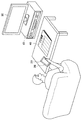
図1は、本開示によるARシステムの構成を示した説明図である。図1に示したように、本開示によるARシステムは、録画装置10と携帯端末20とを含む。この携帯端末20は、実空間画像を撮像し、実空間画像に含まれる実オブジェクトに対応する仮想オブジェクト(以下、「仮想表示」とも言う。)を実オブジェクトに付加することができる。仮想オブジェクトは、ディスプレイ26に表示され得る。なお、実オブジェクトは、実空間画像であってもよく、実空間自体であってもよい。
FIG. 1 is an explanatory diagram showing a configuration of an AR system according to the present disclosure. As shown in FIG. 1, the AR system according to the present disclosure includes a
例えば、実オブジェクトが図1に示したような番組表40である場合、携帯端末20は、番組表40を含む実空間を撮像することにより、番組表40に対応する仮想オブジェクトを実オブジェクトに付加することができる。仮想オブジェクトはディスプレイ26に表示され得る。ユーザは、このような仮想オブジェクトを視認することにより、実空間からは得られない情報を把握することができる。
For example, when the real object is the
また、携帯端末20は、ユーザ操作に応じて処理の実行を制御することができる。ユーザ操作に応じた処理は、携帯端末20により実行されてもよく、携帯端末20からコマンドを受信した装置(例えば、録画装置10)により実行されてもよい。例えば、携帯端末20は、番組の録画予約を行う旨を示すユーザ操作がなされた場合には、番組の録画予約を制御することができる。番組の録画予約を行う旨を示すユーザ操作がなされた場合には、携帯端末20は、録画装置10に対して番組の録画予約を行うためのコマンドを送信し、当該コマンドを受信した録画装置10は、番組の録画予約を行うことができる。
Moreover, the
表示装置50は、例えば、録画装置10により録画された番組が再生された場合に、再生された番組を表示することが可能である。なお、表示装置50は、本開示の実施形態においては、必須の装置ではない。
For example, when the program recorded by the
なお、図1においては、携帯端末20の一例としてスマートフォンを示したが、携帯端末20はスマートフォンに限定されない。例えば、携帯端末20は、PDA(Personal Digital Assistants)、携帯電話、携帯用音楽再生装置、携帯用映像処理装置、または携帯用ゲーム機器であってもよい。さらに、携帯端末20は表示制御装置の一例に過ぎず、表示制御装置はネットワーク側に設けられるサーバであってもよい。
In addition, in FIG. 1, although the smart phone was shown as an example of the
また、図1においては、実オブジェクトの一例として番組表40を示したが、実オブジェクトは番組表40に限定されない。例えば、実オブジェクトは、番組表40と同様に、時間と関連付けられた領域を含む表(例えば、カレンダー、スケジュール表)であってもよい。 In FIG. 1, the program table 40 is shown as an example of a real object, but the real object is not limited to the program table 40. For example, the real object may be a table (for example, a calendar or a schedule table) including an area associated with time, like the program table 40.
ところで、上述したARアプリケーションは、仮想オブジェクトを実オブジェクトに付加することが可能である。しかし、時間と関連付けられた領域が実オブジェクトに含まれる場合であっても、その領域に仮想オブジェクトを付加することは困難である。時間と関連付けられた領域に対して仮想オブジェクトが付加されれば、ユーザにとって利便性が向上する。例えば、番組表40の番組欄に仮想オブジェクトが付加されれば、ユーザが注目すべき番組を特定しやすくなり利便性が向上する。
By the way, the above-described AR application can add a virtual object to a real object. However, even if a real object includes a region associated with time, it is difficult to add a virtual object to that region. If a virtual object is added to an area associated with time, convenience for the user is improved. For example, if a virtual object is added to the program column of the
そこで、上記事情を一着眼点にして本開示の実施形態を創作するに至った。本開示の実施形態によれば、ユーザによる携帯端末20の利便性を向上することが可能である。以下、図2を参照してこのような携帯端末20のハードウェア構成を説明した後、本開示の実施形態について詳細に説明する。
In view of the above circumstances, the present disclosure has been created. According to the embodiment of the present disclosure, it is possible to improve the convenience of the
(携帯端末のハードウェア構成)
図3は、携帯端末20のハードウェア構成を示した説明図である。図3に示したように、携帯端末20は、CPU(Central Processing Unit)201と、ROM(Read Only Memory)202と、RAM(Random Access Memory)203と、入力装置208と、出力装置210と、ストレージ装置211と、ドライブ212と、撮像装置213と、通信装置215とを備える。
(Hardware configuration of mobile device)
FIG. 3 is an explanatory diagram showing the hardware configuration of the
CPU201は、演算処理装置および制御装置として機能し、各種プログラムに従って携帯端末20内の動作全般を制御する。また、CPU201は、マイクロプロセッサであってもよい。ROM202は、CPU201が使用するプログラムや演算パラメータ等を記憶する。RAM203は、CPU201の実行において使用するプログラムや、その実行において適宜変化するパラメータ等を一時記憶する。これらはCPUバスなどから構成されるホストバスにより相互に接続されている。
The
入力装置208は、マウス、キーボード、タッチパネル、ボタン、マイクロフォン、スイッチおよびレバーなどユーザが情報を入力するための入力手段と、ユーザによる入力に基づいて入力信号を生成し、CPU201に出力する入力制御回路などから構成されている。携帯端末20のユーザは、該入力装置208を操作することにより、携帯端末20に対して各種のデータを入力したり処理動作を指示したりすることができる。
The
出力装置210は、例えば、液晶ディスプレイ(LCD)装置、OLED(Organic Light Emitting Diode)装置およびランプなどの表示装置を含む。さらに、出力装置210は、スピーカおよびヘッドホンなどの音声出力装置を含む。例えば、表示装置は、撮像された画像や生成された画像などを表示する。一方、音声出力装置は、音声データ等を音声に変換して出力する。
The
ストレージ装置211は、本実施形態にかかる携帯端末20の記憶部の一例として構成されたデータ格納用の装置である。ストレージ装置211は、記憶媒体、記憶媒体にデータを記録する記録装置、記憶媒体からデータを読み出す読出し装置および記憶媒体に記録されたデータを削除する削除装置などを含んでもよい。このストレージ装置211は、CPU201が実行するプログラムや各種データを格納する。
The
ドライブ212は、記憶媒体用リーダライタであり、携帯端末20に内蔵、あるいは外付けされる。ドライブ212は、装着されている磁気ディスク、光ディスク、光磁気ディスク、または半導体メモリ等のリムーバブル記憶媒体24に記録されている情報を読み出して、RAM203に出力する。また、ドライブ212は、リムーバブル記憶媒体24に情報を書き込むこともできる。
The
撮像装置213は、光を集光する撮影レンズおよびズームレンズなどの撮像光学系、およびCCD(Charge Coupled Device)またはCMOS(Complementary Metal Oxide Semiconductor)などの信号変換素子を備える。撮像光学系は、被写体から発せられる光を集光して信号変換部に被写体像を形成し、信号変換素子は、形成された被写体像を電気的な画像信号に変換する。
The
通信装置215は、例えば、ネットワークに接続するための通信デバイス等で構成された通信インタフェースである。また、通信装置215は、無線LAN(Local Area Network)対応通信装置であっても、LTE(Long Term Evolution)対応通信装置であっても、有線による通信を行うワイヤー通信装置であってもよい。通信装置215は、例えば、ネットワークを介して録画装置10と通信を行うことが可能である。
The
なお、ネットワークは、ネットワークに接続されている装置から送信される情報の有線、または無線の伝送路である。例えば、ネットワークは、インターネット、電話回線網、衛星通信網などの公衆回線網や、Ethernet(登録商標)を含む各種のLAN(Local Area Network)、WAN(Wide Area Network)などを含んでもよい。また、ネットワークは、IP−VPN(Internet Protocol−Virtual Private Network)などの専用回線網を含んでもよい。 The network is a wired or wireless transmission path for information transmitted from a device connected to the network. For example, the network may include a public line network such as the Internet, a telephone line network, and a satellite communication network, various LANs (Local Area Network) including Ethernet (registered trademark), WAN (Wide Area Network), and the like. The network may also include a dedicated line network such as an IP-VPN (Internet Protocol-Virtual Private Network).
<<2.実施形態の説明>>
以上、図1および図2を参照し、本開示によるARシステムの基本構成を説明した。以下、図3〜図14を参照し、本開示による実施形態について詳細に説明する。
<< 2. Description of Embodiment >>
The basic configuration of the AR system according to the present disclosure has been described above with reference to FIGS. 1 and 2. Hereinafter, embodiments according to the present disclosure will be described in detail with reference to FIGS.
(携帯端末の構成)
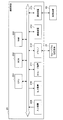
図3は、本実施形態による携帯端末20の構成を示した機能ブロック図である。図3に示したように、本実施形態による携帯端末20は、ディスプレイ26と、タッチパネル27と、撮像装置213と、認識用辞書受信部220と、認識用辞書記憶部222と、状態情報受信部224と、領域情報受信部226と、を備える。また、本実施形態による携帯端末20は、構成情報生成部228と、構成情報記憶部230と、認識部232と、領域判定部234と、表示制御部236と、操作検出部240と、実行制御部244と、コマンド送信部248と、を備える。
(Configuration of mobile device)
FIG. 3 is a functional block diagram showing the configuration of the
ディスプレイ26は、LCDまたはOLEDなどにより構成される表示モジュールである。ディスプレイ26は、表示制御部236による制御に従って多様な画面を表示する。例えば、ディスプレイ26は、実オブジェクトに付加される仮想オブジェクトを表示することができる。実オブジェクトが実空間画像(実空間静止画、または実空間動画)の場合には、実空間画像を表示することもできる。実空間画像は、現在に撮像された空間の画像であってもよく、過去に撮像された実空間の画像であってもよい。
The
また、図3においてはディスプレイ26が携帯端末20の一部として実装される例を示したが、ディスプレイ26は、携帯端末20とは別体に構成されてもよい。また、ディスプレイ26は、ユーザの頭部に装着されるHMD(Head Mounted Display)であってもよい。
3 shows an example in which the
タッチパネル27は、ディスプレイ26に積層されてもよく、ディスプレイ26から離れた場所に配置されてもよい。タッチパネル27は、ユーザの指やタッチペンなどの操作体の近接または接触を検出することができる。タッチパネル27により検出された操作体の近接または接触は、ユーザ操作として操作検出部240に通知される。なお、タッチパネル27は、携帯端末20は、キーボードおよびボタンなどの他の操作用の構成を含んでもよい。
The
撮像装置213は、撮像光学系および信号変換素子を備え、実空間を撮像することにより撮像画像(動画または静止画)を取得する。なお、撮像装置213は、動画撮像用の構成と、静止画撮像用の構成を別個に備えてもよい。
The
認識用辞書受信部220は、認識用辞書サーバ70から実オブジェクトを認識するために使用される認識用辞書を受信する。認識用辞書受信部220は、例えば、ネットワークを介して認識用辞書サーバ70から認識用辞書を受信する。ここで使用されるネットワークは、録画装置10が接続されているネットワークと同一であってもよいし、異なっていてもよい。具体的には、認識用辞書は、各実オブジェクトを識別するための識別情報と各実オブジェクトの特徴量データとが関連付けられてなる。特徴量データは、例えば、SIFT法またはRandom Ferns法に従って実オブジェクトの学習用画像から決定された特徴量の集合であってもよい。
The recognition
認識用辞書記憶部222は、認識用辞書を記憶する。例えば、認識用辞書記憶部222は、認識用辞書受信部220により受信された認識用辞書を記憶することができる。しかしながら、認識用辞書記憶部222により記憶される認識用辞書は、認識用辞書受信部220により受信された認識用辞書に限定されない。例えば、認識用辞書記憶部222は、記憶媒体から読み込まれた認識用辞書を記憶してもよい。
The recognition
状態情報受信部224は、録画装置10から状態情報を受信する。状態情報は、番組の状態を示す情報であり、例えば、番組の録画予約状況(例えば、予約済み、録画済み、未予約など)により示される。録画装置10は、状態情報記憶部110、状態情報送信部120、コマンド受信部130およびコマンド実行部140を備えている。状態情報記憶部110は、状態情報を記憶しており、状態情報送信部120は、状態情報記憶部110により記憶されている状態情報を、ネットワークを介して携帯端末20に送信する。コマンド受信部130およびコマンド実行部140については後に説明する。
The status
領域情報受信部226は、領域情報サーバ80から領域情報を受信する。領域情報受信部226は、例えば、ネットワークを介して領域情報サーバ80から領域情報を受信する。ここで使用されるネットワークは、録画装置10が接続されているネットワークと同一であってもよいし異なっていてもよい。また、認識用辞書サーバ70が接続されているネットワークと同一であってもよいし異なっていてもよい。
The area
ここで、図4を参照し、領域情報の一例について説明する。図4は、領域情報の一例を示した説明図である。領域情報は、実オブジェクトに含まれている領域の位置及び大きさを示す情報である。領域の位置は、例えば、実オブジェクトの所定点の位置を基準とした場合における領域の所定点の位置により表現され得る。 Here, an example of the region information will be described with reference to FIG. FIG. 4 is an explanatory diagram showing an example of the area information. The area information is information indicating the position and size of the area included in the real object. The position of the area can be expressed, for example, by the position of the predetermined point of the area when the position of the predetermined point of the real object is used as a reference.
図4に示した例では、実オブジェクトの左上隅を実オブジェクトの所定点としているが、実オブジェクトの所定点は実オブジェクトの左上隅でなくてもよい。また、図4に示した例では、領域の左上隅を領域の所定点としているが、領域の所定点は領域の左上隅でなくてもよい。また、図4に示した例では、実オブジェクトの所定点の位置を(0,0)と表現し、領域の所定点の位置を(X1,Y1)と表現し、領域の大きさを(W1,H1)と表現しているが、表現の形式は特に限定されない。例えば、これらの値(X1,Y1,W1,H1)は、絶対単位(例えば、実オブジェクトの実寸と同じ単位)であってもよく、相対単位(例えば、実オブジェクトの横または縦の大きさを1とした場合における相対値)であってもよい。
In the example illustrated in FIG. 4, the upper left corner of the real object is the predetermined point of the real object, but the predetermined point of the real object may not be the upper left corner of the real object. In the example shown in FIG. 4, the upper left corner of the region is the predetermined point of the region, but the predetermined point of the region may not be the upper left corner of the region. In the example shown in FIG. 4, the position of the predetermined point of the real object is expressed as (0, 0), the position of the predetermined point of the area is expressed as (X1, Y1), and the size of the area is expressed as (W1 , H1), but the form of expression is not particularly limited. For example, these values (
構成情報生成部228は、状態情報受信部224により受信された状態情報と領域情報受信部226により受信された領域情報とに基づいて構成情報を生成する。ここで、図5を参照し、構成情報の一例について説明する。図5は、構成情報の一例を示した説明図である。構成情報生成部228は、例えば、状態情報受信部224により受信された状態情報と領域情報受信部226により受信された領域情報との間に関連する情報同士が存在すれば、関連する情報同士を関連付けることにより構成情報を生成することができる。
The configuration
例えば、状態情報受信部224により受信された状態情報に番組情報(例えば、番組の放送時間および番組のチャンネル)が付加されており、領域情報受信部226により受信された領域情報に番組情報が付加されている場合には、同一の番組情報が付加されている状態情報および領域情報が関連すると判断し、その状態情報および領域情報を関連付けることにより構成情報を生成することができる。図5に示したように、番組情報には、番組の放送時間および番組のチャンネル以外に番組名が含まれていてもよい。また、番組情報の代わりに、Gコードなどの番組を識別するための情報が使用されてもよい。
For example, program information (for example, program broadcast time and program channel) is added to the status information received by the status
図3に戻って説明を続ける。構成情報記憶部230は、構成情報を記憶する。例えば、構成情報記憶部230は、構成情報生成部228により生成された構成情報を記憶することができる。しかしながら、構成情報記憶部230により記憶される構成情報は、構成情報生成部228により生成された構成情報に限定されない。例えば、構成情報記憶部230は、記憶媒体から読み込まれた構成情報を記憶してもよい。その代わりに、構成情報記憶部230は、所定のサーバから受信された構成情報を記憶してもよい。
Returning to FIG. 3, the description will be continued. The configuration
認識部232は、撮像装置213により撮像された実空間画像に含まれる実オブジェクト、および当該実オブジェクトの実空間画像における位置および姿勢を認識する。例えば、認識部232は、実空間画像から決定される特徴量を認識用辞書記憶部222に記憶されている各実オブジェクトの特徴量と照合することにより、実空間画像に含まれる実オブジェクトを認識する。
The
より具体的には、認識部232は、SIFT法またはRandom Ferns法などの特徴量決定法に従って実空間画像内の実オブジェクトの特徴量を決定し、決定した特徴量を認識用辞書記憶部222に記憶されている各実オブジェクトの特徴量と照合する。そして、認識部232は、実空間画像内の実オブジェクトの特徴量と最も適合する特徴量と関連付けられている実オブジェクトの識別情報、実空間画像における位置および姿勢を認識する。
More specifically, the
なお、実オブジェクトの認識はかかる例に限定されない。例えば、認識部232は、実オブジェクトに関連付けられている既知の図形若しくは記号、人工マーカ(例えば、バーコード若しくはQRコード)または自然マーカなどのマーカを認識することにより、当該実オブジェクトを間接的に認識してもよい。また、認識部232は、既知の図形若しくは記号、人工マーカまたは自然マーカなどの実オブジェクトを認識し、当該実オブジェクトの実空間画像におけるサイズおよび形状から当該実オブジェクトの位置および姿勢を認識してもよい。
Real object recognition is not limited to this example. For example, the
また、上記では、実空間画像に含まれる実オブジェクトの位置および姿勢を画像処理により認識する例を説明したが、実オブジェクトの位置および姿勢の認識方法は画像処理に限定されない。例えば、撮像装置213が向けられている方向、および携帯端末20の現在位置を検出し、検出結果に基づいて実空間画像に含まれている実オブジェクト、実空間画像における当該実オブジェクトの位置および姿勢を推定することも可能である。
In the above description, the example in which the position and orientation of the real object included in the real space image are recognized by image processing has been described. However, the method for recognizing the position and orientation of the real object is not limited to image processing. For example, the direction in which the
あるいは、認識部232は、ピンホールカメラモデルに従って当該実オブジェクトの位置および姿勢を認識してもよい。ピンホールカメラモデルは、OpenGLの透視法(遠近法)の射影変換と同じであり、透視法で作成されるCGの視点モデルは、ピンホールカメラモデルと同一とすることができる。
Or the
図6は、実オブジェクトの位置および姿勢の認識手法の一例を示した説明図であり、特に、ピンホールカメラモデルに従って実オブジェクトの位置および姿勢を認識する手法について示した図である。以下、ピンホールカメラモデルに従って実オブジェクトの位置および姿勢を認識する手法について説明する。 FIG. 6 is an explanatory diagram showing an example of a method for recognizing the position and orientation of a real object, and in particular, a diagram showing a method for recognizing the position and orientation of a real object according to a pinhole camera model. Hereinafter, a method for recognizing the position and orientation of a real object according to a pinhole camera model will be described.
ピンホールカメラモデルにおいて、画像フレーム中の特徴点の位置は下式(1)によって計算され得る。 In the pinhole camera model, the position of the feature point in the image frame can be calculated by the following equation (1).

式(1)は、撮影画像平面に含まれるオブジェクトの点(m)の撮影画像平面の画素位置(すなわち、カメラ座標系によって表現されている位置)と、世界座標系におけるオブジェクトの3次元位置(M)との対応関係を示す式である。撮影画像平面の画素位置は、カメラ座標系によって表現されている。カメラ座標系は、カメラ(撮像装置213)の焦点を原点Cとして、撮影画像平面をXc,Ycの二次元平面により表現し、奥行きをZcとして表現した座標系であり、カメラの動きによって原点Cは移動する。 Expression (1) is obtained by calculating the pixel position (that is, the position expressed by the camera coordinate system) of the object point (m) included in the captured image plane and the three-dimensional position of the object in the world coordinate system ( It is a formula which shows a correspondence relationship with M). The pixel position on the captured image plane is expressed by a camera coordinate system. The camera coordinate system is a coordinate system in which the focus of the camera (imaging device 213) is set as the origin C, the captured image plane is expressed as a two-dimensional plane of Xc and Yc, and the depth is expressed as Zc. Move.
一方、オブジェクトの3次元位置(M)は、カメラの動きによって移動しない原点Oを有するXYZ三軸からなる世界座標系によって示される。この異なる座標系でのオブジェクトの位置の対応関係を示す式が上述のピンホールカメラモデルとして定義される。 On the other hand, the three-dimensional position (M) of the object is indicated by a world coordinate system composed of three XYZ axes having an origin O that does not move due to the movement of the camera. An expression indicating the correspondence between the positions of the objects in the different coordinate systems is defined as the above-described pinhole camera model.
この式に含まれる各値は、
λ:正規化パラメータ
A:カメラ内部パラメータ、
Cw:カメラ位置、
Rw:カメラ回転行列、
を意味している。
Each value included in this expression is
λ: normalization parameter A: camera internal parameter,
Cw: camera position,
Rw: camera rotation matrix,
Means.
さらに、図6に示したように、 Furthermore, as shown in FIG.
なお、カメラ内部パラメータAには、以下の値が含まれる。
f:焦点距離
θ:画像軸の直交性(理想値は90°)
ku:縦軸のスケール(3次元位置のスケールから二次元画像のスケールへの変換)
kv:横軸のスケール(3次元位置のスケールから二次元画像のスケールへの変換)
(u0,v0):画像中心位置
The camera internal parameter A includes the following values.
f: Focal length θ: Image axis orthogonality (ideal value is 90 °)
k u : scale of the vertical axis (conversion from the scale of the three-dimensional position to the scale of the two-dimensional image)
k v : horizontal axis scale (conversion from a 3D position scale to a 2D image scale)
(U 0 , v 0 ): Image center position
このように、世界座標系にある特徴点は位置[M]で表現される。また、カメラは位置[Cw]と姿勢(回転行列)Rwで表現される。カメラの焦点位置・画像中心等はカメラ内部パラメータ[A]で表現される。位置[M]、位置[Cw]およびカメラ内部パラメータ[A]は、下式(4)〜(6)によって表現され得る。 Thus, the feature point in the world coordinate system is expressed by the position [M]. The camera is represented by a position [Cw] and a posture (rotation matrix) Rw. The focal position of the camera, the image center, etc. are expressed by camera internal parameters [A]. The position [M], the position [Cw], and the camera internal parameter [A] can be expressed by the following equations (4) to (6).
based 3 point algorithmを適用して求めることができる。
It can be obtained by applying a based 3 point algorithm.
M. A.
Fischler and R. C. Bolles, “Random sample consensus: A paradigm for model
fitting with applications to image analysis and automated cartography”,
Communications of the ACM, Volume 24 Issue 6 (1981)
MA
Fischler and RC Bolles, “Random sample consensus: A paradigm for model
fitting with applications to image analysis and automated cartography ”,
Communications of the ACM,
なお、携帯端末20がカメラの位置および姿勢を測定できるセンサ、または、カメラの位置および姿勢の変化を測定できるセンサを備える場合には、認識部232は、センサにより検出された値に基づいて、カメラの位置[Cw]と姿勢(回転行列)Rwとを取得してもよい。
In the case where the
このような手法により、実オブジェクトが認識される。認識部232により実オブジェクトが認識された場合、表示制御部236は、実オブジェクトが認識された旨を示す表示を実オブジェクトに付加してもよい。かかる表示をユーザが目にすることにより、実オブジェクトが携帯端末20により認識されていることを把握することができる。実オブジェクトが認識された旨を示す表示は特に限定されない。例えば、実オブジェクトとして番組表40が認識部232により認識された場合、実オブジェクトが認識された旨を示す表示は、番組表40を囲うような枠(例えば、緑色の枠)であってもよいし、番組表40を透明色により塗りつぶすような表示でもよい。
A real object is recognized by such a method. When the real object is recognized by the
認識部232により実オブジェクトが認識されていない場合、表示制御部236は、実オブジェクトが認識されていない旨を示す表示を表示するようディスプレイ26を制御してもよい。かかる表示をユーザが目にすることにより、実オブジェクトが携帯端末20により認識されていないことを把握することができる。実オブジェクトが認識されていない旨を示す表示は特に限定されない。例えば、実オブジェクトが認識されていない旨を示す表示は、「?」マークであってもよい。また、表示制御部236は、「?」マークの隣に認識されていない物体の縮小画像を表示するようディスプレイ26を制御してもよい。
When the real object is not recognized by the
また、認識部232により実オブジェクトが一意に認識されない場合も想定される。かかる場合には、表示制御部236は、認識部232により認識された複数の実オブジェクトを候補としてディスプレイ26に表示させてもよい。そうすれば、ユーザは、ディスプレイ26により表示された複数の実オブジェクトの中から所望の実オブジェクトを見つけた場合には、タッチパネル27に対して所望のオブジェクトを選択する操作を入力することができる。認識部232は、操作検出部240により検出された操作に基づいて、実オブジェクトを認識することができる。
It is also assumed that the real object is not uniquely recognized by the
図3に戻って説明を続ける。領域判定部234は、撮像画像における実オブジェクトに含まれる領域を判定する。領域判定部234は、例えば、構成情報記憶部230により記憶されている構成情報に基づいて領域を判定する。例えば、領域判定部234は、構成情報に含まれている領域情報が示す領域を実オブジェクトに含まれる領域として判定することができる。また、領域判定部234は、認識部232により認識された実オブジェクトの位置および姿勢と構成情報に含まれている領域情報とに基づいて領域を判定することもできる。
Returning to FIG. 3, the description will be continued. The
表示制御部236は、時間(例えば、放送時間)と関連付けられた領域を含む実オブジェクトに仮想オブジェクトを付加する。表示制御部236は、例えば、実オブジェクトに含まれる領域に対して仮想オブジェクトを付加することができる。実オブジェクトに含まれる領域は、領域判定部234により判定され得る。例えば、仮想オブジェクトが実オブジェクトごとに記憶されている場合には、表示制御部236は、実オブジェクトに対応する仮想オブジェクトを領域に対して付加することができる。
The
操作検出部240は、ユーザからの操作を検出する。操作検出部240は、例えば、タッチパネル27に対して入力されたユーザ操作を検出することができる。しかしながら、ユーザ操作の入力は、タッチパネル27以外の入力装置により受け付けられてもよい。例えば、マウス、キーボード、タッチパネル、ボタン、マイクロフォン、スイッチおよびレバーなどの入力装置であってもよい。
The
実行制御部244は、ユーザ操作に応じて処理の実行を制御する。例えば、実行制御部244は、操作検出部240により仮想オブジェクトに対するユーザ操作が検出された場合には、仮想オブジェクトに対応する処理の実行を制御する。かかる処理は、携帯端末20自身により実行されてもよく、携帯端末20以外の装置(例えば、録画装置10)により実行されてもよい。
The
録画装置10に処理を実行させる場合には、携帯端末20のコマンド送信部248により処理の実行を指示するコマンドが録画装置10に送信され、録画装置10のコマンド受信部130によりコマンドが受信される。録画装置10のコマンド実行部140は、コマンド受信部130によりコマンドが受信されると、受信されたコマンドにより指定される処理を実行する。録画装置10により実行される処理としては、録画されている番組の再生および消去、番組の録画予約、番組の予約中止などが想定される。
When causing the
ここで、図7を参照し、仮想オブジェクトの表示の一例について説明する。図7は、仮想オブジェクトの表示の一例を示した説明図である。図7に示したように、実オブジェクトが番組表40である場合、複数の領域の各々は、放送時間およびチャンネルと関連付けられており、例えば、表示制御部236は、実オブジェクトの各領域に対して、仮想オブジェクトV21、V23、V24を付加することができる。図7に示した例では、領域全体を透明色により塗りつぶすような仮想オブジェクトが付加されている。
Here, an example of the display of the virtual object will be described with reference to FIG. FIG. 7 is an explanatory diagram showing an example of display of a virtual object. As shown in FIG. 7, when the real object is the
しかしながら、表示制御部236は、実オブジェクトの領域全体に対して仮想オブジェクトを付加する必要はない。例えば、表示制御部236は、領域の一部に対して仮想オブジェクトを付加してもよく、領域から伸びた引き出し線の先に仮想オブジェクトを付加してもよい。
However, the
表示制御部236は、各領域に対して同一の仮想オブジェクトを付加してもよいが、番組に関して保存されている情報に応じた仮想オブジェクトを、番組に対応する領域に付加してもよい。図7に示した例では、表示制御部236は、状態情報が「録画済み」である番組に対応する領域には、「録画済み」に対応する仮想オブジェクトV11、V12を付加している。また、表示制御部236は、状態情報が「未予約」である番組に対応する領域には、「未予約」に対応する仮想オブジェクトV13を付加している。また、表示制御部236は、状態情報が「予約済み」である番組に対応する領域には、「予約済み」に対応する仮想オブジェクトV14を付加している。
The
表示制御部236により付加される仮想オブジェクトは、例えば、携帯端末20の記憶部により記憶されている。仮想オブジェクトが状態情報ごとに記憶されていれば、表示制御部236は、状態情報に関連する仮想オブジェクトを領域に対して付加することができる。仮想オブジェクトは、テキスト形式であってもよいし、イメージ形式であってもよい。
The virtual object added by the
図7に示した例において、仮想オブジェクトV11は、「再生」という文字により表現されているが、「再生」の省略文字(例えば、「P」)などにより表現されてもよい。また、仮想オブジェクトV11は、再生を示す記号により表現されてもよい。同様に、仮想オブジェクトV12は、「消去」という文字により表現されているが、「消去」の省略文字(例えば、「D」)などにより表現されてもよい。また、仮想オブジェクトV12は、消去を示す記号により表現されてもよい。 In the example illustrated in FIG. 7, the virtual object V11 is represented by the characters “play”, but may be represented by an abbreviation of “play” (for example, “P”). The virtual object V11 may be expressed by a symbol indicating reproduction. Similarly, the virtual object V <b> 12 is expressed by a character “Erase”, but may be expressed by an abbreviation of “Erase” (for example, “D”). The virtual object V12 may be expressed by a symbol indicating erasure.
同様に、仮想オブジェクトV13は、「録画予約」という文字により表現されているが、「録画予約」の省略文字(例えば、「R」)などにより表現されてもよい。また、仮想オブジェクトV13は、録画予約を示す記号により表現されてもよい。同様に、仮想オブジェクトV14は、「予約中止」という文字により表現されているが、「予約中止」の省略文字(例えば、「C」)などにより表現されてもよい。また、仮想オブジェクトV14は、予約中止を示す記号により表現されてもよい。 Similarly, the virtual object V13 is expressed by the characters “recording reservation”, but may be expressed by an abbreviation of “recording reservation” (for example, “R”). The virtual object V13 may be expressed by a symbol indicating a recording reservation. Similarly, the virtual object V14 is expressed by the characters “reservation cancellation”, but may be expressed by an abbreviation of “reservation cancellation” (for example, “C”). The virtual object V14 may be expressed by a symbol indicating reservation cancellation.
さらに、図7に示したように、表示制御部236は、現在時刻を実オブジェクトに付加してもよい。例えば、携帯端末20は、携帯端末20の内部又は外部に設置されている時計から現在時刻を取得し、取得した現在時刻を実オブジェクトに付加することができる。また、図7に示したように、実オブジェクトにおける現在時刻に対応する位置にラインを付加してもよい。このような情報が付加されれば、これから放送が開始する番組、既に放送が開始されている番組、既に放送が終了している番組などを容易に把握することができる。
Further, as illustrated in FIG. 7, the
図7に示した例において、例えば、実行制御部244は、操作検出部240により仮想オブジェクトV11に対するユーザ操作が検出された場合には、その番組に関する「再生」の実行を制御する。実行制御部244は、操作検出部240により仮想オブジェクトV12に対するユーザ操作が検出された場合には、その番組に関する「消去」の実行を制御する。実行制御部244は、操作検出部240により仮想オブジェクトV13に対するユーザ操作が検出された場合には、その番組に関する「録画予約」の実行を制御する。実行制御部244は、操作検出部240により仮想オブジェクトV14に対するユーザ操作が検出された場合には、その番組に関する「予約中止」の実行を制御する。
In the example illustrated in FIG. 7, for example, when the
ここで、図8を参照し、仮想オブジェクトの表示の他の一例について説明する。図8は、仮想オブジェクトの表示の他の一例を示した説明図である。図8に示した例では、表示制御部236が、番組に対応する領域の一例として番組表40の左隅の欄に仮想オブジェクトを付加している。
Here, another example of the display of the virtual object will be described with reference to FIG. FIG. 8 is an explanatory view showing another example of the display of the virtual object. In the example shown in FIG. 8, the
表示制御部236は、状態情報が「録画済み」である番組に対応する領域には、番組名(例えば、「おひさま」、「みつけた」など)と「録画済み」との組み合わせにより構成される仮想オブジェクトV111、V112を付加している。また、表示制御部236は、状態情報が「未予約」である番組に対応する領域には、番組名(例えば、「歌う人」など)と「未予約」との組み合わせにより構成される仮想オブジェクトV141を付加している。また、表示制御部236は、状態情報が「予約済み」である番組に対応する領域には、番組名(例えば、「歴史」など)と「予約済み」との組み合わせにより構成される仮想オブジェクトV131を付加している。
In the area corresponding to the program whose status information is “recorded”, the
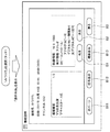
ここで、図9を参照し、仮想オブジェクトに対するユーザ操作により表示される操作画面の一例について説明する。図9は、仮想オブジェクトに対するユーザ操作により表示される操作画面の一例を示した説明図である。図9に示した例では、表示制御部236は、ユーザ操作を行うための仮想オブジェクトを実オブジェクトに付加していない。
Here, an example of an operation screen displayed by a user operation on the virtual object will be described with reference to FIG. FIG. 9 is an explanatory diagram illustrating an example of an operation screen displayed by a user operation on a virtual object. In the example illustrated in FIG. 9, the
その代わりに、図9に示した例では、表示制御部236は、操作検出部240により仮想オブジェクトV23(番組名が「みつけた」である番組に対応する領域に付加された仮想オブジェクト)に対するユーザ操作が検出された場合には、その番組に関する操作画面を表示するように制御することができる。表示制御部236は、その番組の状態情報に応じた処理を実行制御するためのボタンを操作画面に含めることができる。表示制御部236は、例えば、番組の状態情報が「録画済み」であれば、図9に示したように、操作画面に、ボタンB1、B2、B3を含めることができる。
Instead, in the example shown in FIG. 9, the
例えば、実行制御部244は、操作検出部240によりボタンB1に対するユーザ操作が検出された場合には、その番組に関する「再生」の実行を制御する。実行制御部244は、操作検出部240によりボタンB2に対するユーザ操作が検出された場合には、その番組に関する「消去」の実行を制御する。実行制御部244は、操作検出部240によりボタンB3に対するユーザ操作が検出された場合には、実オブジェクトの表示に戻るように制御する。
For example, when a user operation on the button B1 is detected by the
続いて、図10を参照し、仮想オブジェクトに対するユーザ操作により表示される操作画面の他の一例について説明する。図10は、仮想オブジェクトに対するユーザ操作により表示される操作画面の他の一例を示した説明図である。図10に示した例では、図9に示した例と同様に、表示制御部236は、ユーザ操作を行うための仮想オブジェクトを実オブジェクトに付加していない。
Next, another example of the operation screen displayed by a user operation on the virtual object will be described with reference to FIG. FIG. 10 is an explanatory diagram showing another example of the operation screen displayed by the user operation on the virtual object. In the example illustrated in FIG. 10, as in the example illustrated in FIG. 9, the
図10に示した例においても、図9に示した例と同様に、表示制御部236は、操作検出部240により仮想オブジェクトV23に対するユーザ操作が検出された場合には、その番組に関する操作画面を表示するように制御することができる。図9に示した例と同様に、表示制御部236は、例えば、番組の状態情報が「録画済み」であれば、図10に示したように、ボタンB1、B2、B3を操作画面に含めることができる。表示制御部236は、その他にも、ボタンB11、B12、B13などを操作画面に含めることができる。
Also in the example illustrated in FIG. 10, as in the example illustrated in FIG. 9, when the
続いて、図11を参照し、ユーザ操作により表示される操作画面の一例について説明する。図11は、ユーザ操作により表示される操作画面の一例を示した説明図である。図11に示した例では、表示制御部236は、操作検出部240により仮想オブジェクトが付加されていない領域(番組名が「歌う人」である番組に対応する領域)に対するユーザ操作が検出された場合には、その番組に関する操作画面を表示するように制御することができる。表示制御部236は、その番組の状態情報に応じた処理を実行制御するためのボタンを操作画面に含めることができる。表示制御部236は、例えば、番組の状態情報が「未予約」であれば、図11に示したように、操作画面に、ボタンB4、B3を含めることができる。
Next, an example of an operation screen displayed by a user operation will be described with reference to FIG. FIG. 11 is an explanatory diagram showing an example of an operation screen displayed by a user operation. In the example illustrated in FIG. 11, the
例えば、実行制御部244は、操作検出部240によりボタンB4に対するユーザ操作が検出された場合には、その番組に関する「録画予約」の実行を制御する。実行制御部244は、操作検出部240によりボタンB3に対するユーザ操作が検出された場合には、実オブジェクトの表示に戻るように制御する。
For example, when the
続いて、図12を参照し、ユーザ操作により表示される操作画面の他の一例について説明する。図12は、ユーザ操作により表示される操作画面の他の一例を示した説明図である。図12に示した例では、図11に示した例と同様に、表示制御部236は、操作検出部240により仮想オブジェクトが付加されていない領域(番組名が「歌う人」である番組に対応する領域)に対するユーザ操作が検出された場合には、その番組に関する操作画面を表示するように制御することができる。
Next, another example of the operation screen displayed by a user operation will be described with reference to FIG. FIG. 12 is an explanatory diagram showing another example of the operation screen displayed by the user operation. In the example illustrated in FIG. 12, as in the example illustrated in FIG. 11, the
図12に示した例においても、図11に示した例と同様に、表示制御部236は、操作検出部240により仮想オブジェクトが付加されていない領域に対するユーザ操作が検出された場合には、その番組に関する操作画面を表示するように制御することができる。図11に示した例と同様に、表示制御部236は、例えば、番組の状態情報が「録画済み」であれば、図11に示したように、ボタンB4、B3を操作画面に含めることができる。表示制御部236は、その他にも、ボタンB11、B12、B13などを操作画面に含めることができる。
Also in the example shown in FIG. 12, as in the example shown in FIG. 11, when the
以上説明したように、本実施形態による携帯端末20は、領域(例えば、時間と関連付けられた領域)を含む実オブジェクトをユーザが閲覧する場合、その領域に対して仮想オブジェクトが付加される。このため、ユーザは注目すべき領域を把握でき、ユーザに対する利便性を向上することが可能である。
As described above, when the user views a real object including an area (for example, an area associated with time), the
(携帯端末の動作)
続いて、図13および図14を参照し、本実施形態による携帯端末20の動作を説明する。図13は、実オブジェクト撮像の前段階としてなされる動作を示したシーケンス図である。
(Mobile device operation)
Subsequently, the operation of the
図13に示したように、実オブジェクト撮像の前段階おいては、まず、認識用辞書サーバ70は、認識用辞書を送信する(S11)。認識用辞書受信部220は、認識用辞書サーバ70から送信された認識用辞書を受信し(S12)、認識用辞書記憶部222は、認識用辞書受信部220により受信された認識用辞書を記憶する(S13)。
As shown in FIG. 13, in the previous stage of real object imaging, first, the
S11〜S13に続いて、またはS11〜S13以前に、領域情報サーバ80は、領域情報を携帯端末20に送信する(S21)。次いで、領域情報受信部226は、領域情報サーバ80から送信された領域情報を受信する(S22)。S21〜S22に続いて、またはS21〜S22以前に、録画装置10は、状態情報を送信する(S23)。次いで、状態情報受信部224は、録画装置10から送信された状態情報を受信する(S24)。構成情報生成部228は、領域情報と状態情報とに基づいて、構成情報を生成し(S25)、構成情報記憶部230は、構成情報生成部228により生成された構成情報を記憶する(S26)。
Subsequent to S11 to S13 or before S11 to S13, the
図14は、実オブジェクト撮像以降の動作を示したシーケンス図である。図14に示したように、実オブジェクト撮像以降においては、まず、撮像装置213は、実オブジェクトを撮像する(S31)。次いで、認識部232は、撮像画像から実オブジェクトを認識し(S32)、領域判定部234は、認識部232による認識結果と構成情報とに基づいて実オブジェクトの領域を判定する(S33)。表示制御部236は、領域判定部234により判定された領域に仮想表示を付加する(S34)。
FIG. 14 is a sequence diagram showing operations after real object imaging. As shown in FIG. 14, after the real object is imaged, the
操作検出部240により仮想表示に対するユーザ操作が検出されない場合には(S35において「NO」の場合)、実行制御部244は、S35に示された動作を繰り返すように制御する。操作検出部240により仮想表示に対するユーザ操作が検出された場合には(S35において「YES」の場合)、コマンド送信部248は、実行制御部244による制御により、仮想表示に応じたコマンドを録画装置10に送信する(S36)。録画装置10のコマンド受信部130は、携帯端末20からコマンドを受信すると(S41)、コマンド実行部140は、コマンド受信部130により受信されたコマンドを実行する(S42)。
When the user operation for the virtual display is not detected by the operation detection unit 240 (in the case of “NO” in S35), the
<<3.むすび>>
以上説明したように、本開示による携帯端末20は、領域(例えば、時間と関連付けられた領域)を含む実オブジェクトをユーザが閲覧する場合、その領域に対して仮想オブジェクトが付加される。このため、ユーザは注目すべき領域を把握でき、ユーザに対する利便性を向上することが可能である。本開示による携帯端末20によれば、ユーザは、直感的な操作により所望の情報に迅速にアクセスすることができる。
<< 3. Conclusion >>
As described above, in the
なお、添付図面を参照しながら本開示の好適な実施形態について詳細に説明したが、本開示の技術的範囲はかかる例に限定されない。本開示の技術分野における通常の知識を有する者であれば、特許請求の範囲に記載された技術的思想の範疇内において、各種の変更例または修正例に想到し得ることは明らかであり、これらについても、当然に本開示の技術的範囲に属するものと了解される。 In addition, although preferred embodiment of this indication was described in detail, referring an accompanying drawing, the technical scope of this indication is not limited to this example. It is obvious that a person having ordinary knowledge in the technical field of the present disclosure can come up with various changes or modifications within the scope of the technical idea described in the claims. Of course, it is understood that it belongs to the technical scope of the present disclosure.
例えば、上記では、実オブジェクトの認識の機能、構成情報の生成の機能、領域判定の機能などを、携帯端末20が有する例を主に説明したが、かかる機能は、携帯端末20の代わりにサーバが有していてもよい。例えば、携帯端末20が撮像画像をサーバに送信した場合、サーバは携帯端末20の代わりに撮像画像から実オブジェクトを認識してもよい。また、例えば、サーバは携帯端末20の代わりに構成情報を生成してもよい。また、例えば、サーバは携帯端末20の代わりに領域を判定してもよい。このように、本開示の技術は、クラウドコンピューティングにも適用することが可能である。
For example, in the above description, an example in which the
例えば、上記では、静止画操作モードへの遷移のトリガとなるユーザ操作の検出例として、タッチパネル27によって検出されるタッチパネル27への操作によって検出される携帯端末20の動きを説明したが、ユーザ操作はかかる例に限定されない。他のユーザ操作の検出例として、モーションセンサによる検出、ユーザのジェスチャ認識が挙げられる。ユーザのジェスチャは、撮像装置213により取得される画像に基づいて認識することも、他の撮像系により取得される画像に基づいて認識することも可能である。なお、撮像装置213または他の撮像系は、赤外線カメラ、Depthカメラなどの機能によりユーザのジェスチャを撮像してもよい。
For example, in the above description, the movement of the
また、上記実施形態では、表示制御装置が携帯端末20である例を主に説明したが、表示制御装置は、TVやディスプレイ装置など、携帯端末20より比較的大きめの装置であってもよい。例えば、表示制御装置側からユーザを撮像する撮像系を表示制御装置に接続しまたは内蔵した上でユーザの全身を映すことのできる大型のディスプレイを利用することにより、ユーザ自身を映す鏡のような機能を構成し、ユーザ自身に仮想オブジェクトを重畳して当該仮想オブジェクトを操作させるようなARアプリケーションを実現することも可能である。
In the above embodiment, the example in which the display control device is the
また、上記では、携帯端末20からのコマンドが録画装置10により実行される例を主に説明したが、録画装置10の代わりにコマンドを実行することができる装置を使用してもよい。例えば、録画装置10の代わりに、家電機器(例えば、撮像装置、映像再生装置など)を使用してもよい。かかる場合、コマンドは、コンテンツデータ(静止画、動画など)を表示させるためのコマンドや、コンテンツデータを削除させるためのコマンドであってもよい。
In the above description, the example in which the command from the
また、上記では、実オブジェクトとして番組表40が使用される例を主に説明したが、実オブジェクトとしては、番組表40の代わりに、カレンダー、スケジュール表などを使用してもよい。スケジュール表は、会社において使用される出欠管理表や、社員スケジュール管理表であってもよい。
In the above description, the example in which the
また、上記では、仮想オブジェクトに対するユーザ操作が検出された場合に、携帯端末20は、録画装置10に対するコマンドを送信する例を主に説明したが、表示装置50に対してコマンドを送信してもよい。かかる場合、送信されるコマンドは、ユーザ操作がなされた仮想オブジェクトに対応するチャンネルへの変更であってもよい。
In the above description, the example in which the
また、本明細書の携帯端末20、または録画装置10の動作における各ステップは、必ずしもシーケンス図として記載された順序に沿って時系列に処理する必要はない。例えば、携帯端末20、または録画装置10の動作における各ステップは、シーケンス図として記載した順序と異なる順序で処理されても、並列的に処理されてもよい。
Further, each step in the operation of the
また、携帯端末20、または録画装置10に内蔵されるCPU、ROMおよびRAMなどのハードウェアを、上述した携帯端末20、または録画装置10の各構成と同等の機能を発揮させるためのコンピュータプログラムも作成可能である。また、該コンピュータプログラムを記憶させた記憶媒体も提供される。
In addition, a computer program for causing hardware such as a CPU, ROM, and RAM incorporated in the
また、以下のような構成も本開示の技術的範囲に属する。
(1)
時間と関連付けられた領域を含む実オブジェクトに仮想表示を付加する表示制御部を備え、
前記表示制御部は、
前記領域に対して前記仮想表示を付加する、表示制御装置。
(2)
前記実オブジェクトは、
放送時間およびチャンネルと関連付けられた複数の領域を含む番組表である、
(1)に記載の表示制御装置。
(3)
前記表示制御部は、
番組に関して保存されている情報に応じた仮想表示を、前記番組に対応する領域に付加する、
(1)または(2)に記載の表示制御装置。
(4)
前記表示制御部は、
番組に関して保存されている情報が、前記番組が録画済みである旨を示す場合には、録画されている番組の再生を制御するための仮想表示を付加する、
(1)〜(3)のいずれか一項に記載の表示制御装置。
(5)
前記表示制御部は、
番組に関して保存されている情報が、前記番組が録画済みである旨を示す場合には、録画されている番組の消去を制御するための仮想表示を付加する、
(1)〜(3)のいずれか一項に記載の表示制御装置。
(6)
前記表示制御部は、
番組に関して保存されている情報が、前記番組が未予約である旨を示す場合には、前記番組の録画予約を制御するための仮想表示を付加する、
(1)〜(3)のいずれか一項に記載の表示制御装置。
(7)
前記表示制御部は、
番組に関して保存されている情報が、前記番組が予約済みである旨を示す場合には、前記番組の予約中止を制御するための仮想表示を付加する、
(1)〜(3)のいずれか一項に記載の表示制御装置。
(8)
前記表示制御装置は、
前記仮想表示に対するユーザ操作を検出する操作検出部と、
前記ユーザ操作に応じて処理の実行を制御する実行制御部と、
をさらに備える、(1)〜(7)のいずれか一項に記載の表示制御装置。
(9)
前記実行制御部は、
前記操作検出部により前記仮想表示に対するユーザ操作が検出された場合に、前記仮想表示に対応する処理の実行を制御する、
(8)に記載の表示制御装置。
(10)
前記表示制御装置は、
前記実オブジェクトの撮像画像から前記実オブジェクトを認識する認識部と、
前記撮像画像における前記領域を判定する領域判定部と、
をさらに備える、(1)〜(9)のいずれか一項に記載の表示制御装置。
(11)
時間と関連付けられた領域を含む実オブジェクトの当該領域に対して仮想表示を付加する、表示制御方法。
(12)
コンピュータを、
時間と関連付けられた領域を含む実オブジェクトに仮想表示を付加する表示制御部を備え、
前記表示制御部は、
前記領域に対して前記仮想表示を付加する、表示制御装置として機能させるためのプログラム。
The following configurations also belong to the technical scope of the present disclosure.
(1)
A display control unit for adding a virtual display to a real object including an area associated with time;
The display control unit
A display control apparatus for adding the virtual display to the area.
(2)
The real object is
A program listing that includes multiple regions associated with airtime and channels,
The display control apparatus according to (1).
(3)
The display control unit
Adding a virtual display according to information stored about the program to an area corresponding to the program;
The display control apparatus according to (1) or (2).
(4)
The display control unit
If the information stored about the program indicates that the program has been recorded, a virtual display is added to control the playback of the recorded program;
The display control apparatus according to any one of (1) to (3).
(5)
The display control unit
If the information stored about the program indicates that the program has been recorded, a virtual display is added to control the erasure of the recorded program;
The display control apparatus according to any one of (1) to (3).
(6)
The display control unit
If the information stored for the program indicates that the program is unreserved, add a virtual display to control the recording reservation of the program;
The display control apparatus according to any one of (1) to (3).
(7)
The display control unit
If the information stored for the program indicates that the program is reserved, add a virtual display to control reservation cancellation of the program;
The display control apparatus according to any one of (1) to (3).
(8)
The display control device includes:
An operation detection unit for detecting a user operation on the virtual display;
An execution control unit that controls execution of processing in accordance with the user operation;
The display control apparatus according to any one of (1) to (7), further including:
(9)
The execution control unit
When a user operation on the virtual display is detected by the operation detection unit, the execution of processing corresponding to the virtual display is controlled.
The display control apparatus according to (8).
(10)
The display control device includes:
A recognition unit for recognizing the real object from a captured image of the real object;
An area determination unit for determining the area in the captured image;
The display control apparatus according to any one of (1) to (9), further including:
(11)
A display control method for adding a virtual display to an area of a real object including an area associated with time.
(12)
Computer
A display control unit for adding a virtual display to a real object including an area associated with time;
The display control unit
A program for functioning as a display control device for adding the virtual display to the area.
20 携帯端末
222 認識用辞書記憶部
224 状態情報受信部
226 領域情報受信部
228 構成情報生成部
230 構成情報記憶部
232 認識部
234 領域判定部
236 表示制御部
240 操作検出部
244 実行制御部
248 コマンド送信部
V11〜V14 仮想オブジェクト(仮想表示)
V111、V131、V141 仮想オブジェクト(仮想表示)
V21、V23 仮想オブジェクト(仮想表示)
20
V111, V131, V141 Virtual object (virtual display)
V21, V23 Virtual object (virtual display)
Claims (12)
前記表示制御部は、
前記領域に対して前記仮想表示を付加する、表示制御装置。 A display control unit for adding a virtual display to a real object including an area associated with time;
The display control unit
A display control apparatus for adding the virtual display to the area.
放送時間およびチャンネルと関連付けられた複数の領域を含む番組表である、
請求項1に記載の表示制御装置。 The real object is
A program listing that includes multiple regions associated with airtime and channels,
The display control apparatus according to claim 1.
番組に関して保存されている情報に応じた仮想表示を、前記番組に対応する領域に付加する、
請求項2に記載の表示制御装置。 The display control unit
Adding a virtual display according to information stored about the program to an area corresponding to the program;
The display control apparatus according to claim 2.
番組に関して保存されている情報が、前記番組が録画済みである旨を示す場合には、録画されている番組の再生を制御するための仮想表示を付加する、
請求項3に記載の表示制御装置。 The display control unit
If the information stored about the program indicates that the program has been recorded, a virtual display is added to control the playback of the recorded program;
The display control apparatus according to claim 3.
番組に関して保存されている情報が、前記番組が録画済みである旨を示す場合には、録画されている番組の消去を制御するための仮想表示を付加する、
請求項3に記載の表示制御装置。 The display control unit
If the information stored about the program indicates that the program has been recorded, a virtual display is added to control the erasure of the recorded program;
The display control apparatus according to claim 3.
番組に関して保存されている情報が、前記番組が未予約である旨を示す場合には、前記番組の録画予約を制御するための仮想表示を付加する、
請求項3に記載の表示制御装置。 The display control unit
If the information stored for the program indicates that the program is unreserved, add a virtual display to control the recording reservation of the program;
The display control apparatus according to claim 3.
番組に関して保存されている情報が、前記番組が予約済みである旨を示す場合には、前記番組の予約中止を制御するための仮想表示を付加する、
請求項3に記載の表示制御装置。 The display control unit
If the information stored for the program indicates that the program is reserved, add a virtual display to control reservation cancellation of the program;
The display control apparatus according to claim 3.
前記仮想表示に対するユーザ操作を検出する操作検出部と、
前記ユーザ操作に応じて処理の実行を制御する実行制御部と、
をさらに備える、請求項1に記載の表示制御装置。 The display control device includes:
An operation detection unit for detecting a user operation on the virtual display;
An execution control unit that controls execution of processing in accordance with the user operation;
The display control apparatus according to claim 1, further comprising:
前記操作検出部により前記仮想表示に対するユーザ操作が検出された場合に、前記仮想表示に対応する処理の実行を制御する、
をさらに備える、請求項8に記載の表示制御装置。 The execution control unit
When a user operation on the virtual display is detected by the operation detection unit, the execution of processing corresponding to the virtual display is controlled.
The display control apparatus according to claim 8, further comprising:
前記実オブジェクトの撮像画像から前記実オブジェクトを認識する認識部と、
前記撮像画像における前記領域を判定する領域判定部と、
をさらに備える、請求項1に記載の表示制御装置。 The display control device includes:
A recognition unit for recognizing the real object from a captured image of the real object;
An area determination unit for determining the area in the captured image;
The display control apparatus according to claim 1, further comprising:
時間と関連付けられた領域を含む実オブジェクトに仮想表示を付加する表示制御部を備え、
前記表示制御部は、
前記領域に対して前記仮想表示を付加する、表示制御装置として機能させるためのプログラム。
Computer
A display control unit for adding a virtual display to a real object including an area associated with time;
The display control unit
A program for functioning as a display control device for adding the virtual display to the area.
Priority Applications (3)
| Application Number | Priority Date | Filing Date | Title |
|---|---|---|---|
| JP2011137181A JP2013004001A (en) | 2011-06-21 | 2011-06-21 | Display control device, display control method, and program |
| US13/495,606 US20120327118A1 (en) | 2011-06-21 | 2012-06-13 | Display control apparatus, display control method and program |
| CN2012102003293A CN102866825A (en) | 2011-06-21 | 2012-06-14 | Display control apparatus, display control method and program |
Applications Claiming Priority (1)
| Application Number | Priority Date | Filing Date | Title |
|---|---|---|---|
| JP2011137181A JP2013004001A (en) | 2011-06-21 | 2011-06-21 | Display control device, display control method, and program |
Publications (2)
| Publication Number | Publication Date |
|---|---|
| JP2013004001A true JP2013004001A (en) | 2013-01-07 |
| JP2013004001A5 JP2013004001A5 (en) | 2014-07-03 |
Family
ID=47361428
Family Applications (1)
| Application Number | Title | Priority Date | Filing Date |
|---|---|---|---|
| JP2011137181A Withdrawn JP2013004001A (en) | 2011-06-21 | 2011-06-21 | Display control device, display control method, and program |
Country Status (3)
| Country | Link |
|---|---|
| US (1) | US20120327118A1 (en) |
| JP (1) | JP2013004001A (en) |
| CN (1) | CN102866825A (en) |
Cited By (1)
| Publication number | Priority date | Publication date | Assignee | Title |
|---|---|---|---|---|
| JP2020520000A (en) * | 2017-05-05 | 2020-07-02 | ユニティ アイピーアール エイピーエスUnity Ipr Aps | Contextual application in mixed reality environment |
Families Citing this family (3)
| Publication number | Priority date | Publication date | Assignee | Title |
|---|---|---|---|---|
| JP5790692B2 (en) * | 2013-03-29 | 2015-10-07 | ソニー株式会社 | Information processing apparatus, information processing method, and recording medium |
| EP3163358B1 (en) * | 2015-10-29 | 2018-03-28 | X-Rite Switzerland GmbH | Visualisation device |
| CN108279859B (en) * | 2018-01-29 | 2021-06-22 | 深圳市洲明科技股份有限公司 | Control system and control method of large-screen display wall |
Family Cites Families (8)
| Publication number | Priority date | Publication date | Assignee | Title |
|---|---|---|---|---|
| US8316450B2 (en) * | 2000-10-10 | 2012-11-20 | Addn Click, Inc. | System for inserting/overlaying markers, data packets and objects relative to viewable content and enabling live social networking, N-dimensional virtual environments and/or other value derivable from the content |
| US7325244B2 (en) * | 2001-09-20 | 2008-01-29 | Keen Personal Media, Inc. | Displaying a program guide responsive to electronic program guide data and program recording indicators |
| US7493646B2 (en) * | 2003-01-30 | 2009-02-17 | United Video Properties, Inc. | Interactive television systems with digital video recording and adjustable reminders |
| US8763038B2 (en) * | 2009-01-26 | 2014-06-24 | Sony Corporation | Capture of stylized TV table data via OCR |
| US8427424B2 (en) * | 2008-09-30 | 2013-04-23 | Microsoft Corporation | Using physical objects in conjunction with an interactive surface |
| US9788043B2 (en) * | 2008-11-07 | 2017-10-10 | Digimarc Corporation | Content interaction methods and systems employing portable devices |
| CN101561989A (en) * | 2009-05-20 | 2009-10-21 | 北京水晶石数字科技有限公司 | Method for exhibiting panoramagram |
| KR101657565B1 (en) * | 2010-04-21 | 2016-09-19 | 엘지전자 주식회사 | Augmented Remote Controller and Method of Operating the Same |
-
2011
- 2011-06-21 JP JP2011137181A patent/JP2013004001A/en not_active Withdrawn
-
2012
- 2012-06-13 US US13/495,606 patent/US20120327118A1/en not_active Abandoned
- 2012-06-14 CN CN2012102003293A patent/CN102866825A/en active Pending
Cited By (2)
| Publication number | Priority date | Publication date | Assignee | Title |
|---|---|---|---|---|
| JP2020520000A (en) * | 2017-05-05 | 2020-07-02 | ユニティ アイピーアール エイピーエスUnity Ipr Aps | Contextual application in mixed reality environment |
| US10984604B2 (en) | 2017-05-05 | 2021-04-20 | Unity IPR ApS | Contextual applications in a mixed reality environment |
Also Published As
| Publication number | Publication date |
|---|---|
| US20120327118A1 (en) | 2012-12-27 |
| CN102866825A (en) | 2013-01-09 |
Similar Documents
| Publication | Publication Date | Title |
|---|---|---|
| US11188187B2 (en) | Information processing apparatus, information processing method, and recording medium | |
| CN109635621B (en) | System and method for recognizing gestures based on deep learning in first-person perspective | |
| JP5765019B2 (en) | Display control apparatus, display control method, and program | |
| KR102173123B1 (en) | Method and apparatus for recognizing object of image in electronic device | |
| CN102906671B (en) | Gesture input device and gesture input method | |
| KR102362117B1 (en) | Electroninc device for providing map information | |
| US20190333478A1 (en) | Adaptive fiducials for image match recognition and tracking | |
| Langlotz et al. | Online creation of panoramic augmented reality annotations on mobile phones | |
| KR20190108181A (en) | Spherical video editing | |
| KR101623041B1 (en) | System and method for managing markers coexisting mixed space, and the recording media storing the program performing the said method | |
| US9898090B2 (en) | Apparatus, method and recording medium for controlling user interface using input image | |
| JP6493471B2 (en) | Video playback method, computer processing system, and video playback program | |
| JP2013141207A (en) | Multi-user interaction with handheld projectors | |
| EP3172721B1 (en) | Method and system for augmenting television watching experience | |
| JP2013004001A (en) | Display control device, display control method, and program | |
| JP5831764B2 (en) | Image display apparatus and program | |
| WO2018006481A1 (en) | Motion-sensing operation method and device for mobile terminal | |
| CN111913674A (en) | Virtual content display method, device, system, terminal equipment and storage medium | |
| US10133966B2 (en) | Information processing apparatus, information processing method, and information processing system | |
| JP5446700B2 (en) | Information processing apparatus, information processing method, and program | |
| GB2513865A (en) | A method for interacting with an augmented reality scene | |
| US20130076622A1 (en) | Method and apparatus for determining input | |
| CN111913560A (en) | Virtual content display method, device, system, terminal equipment and storage medium | |
| CN115278084A (en) | Image processing method, image processing device, electronic equipment and storage medium | |
| CN112529770A (en) | Image processing method, image processing device, electronic equipment and readable storage medium |
Legal Events
| Date | Code | Title | Description |
|---|---|---|---|
| A521 | Request for written amendment filed |
Free format text: JAPANESE INTERMEDIATE CODE: A523 Effective date: 20140520 |
|
| A621 | Written request for application examination |
Free format text: JAPANESE INTERMEDIATE CODE: A621 Effective date: 20140520 |
|
| A761 | Written withdrawal of application |
Free format text: JAPANESE INTERMEDIATE CODE: A761 Effective date: 20150116 |
|
| A977 | Report on retrieval |
Free format text: JAPANESE INTERMEDIATE CODE: A971007 Effective date: 20150123 |