CN110253386B - Shaping and polishing device for die castings - Google Patents
Shaping and polishing device for die castings Download PDFInfo
- Publication number
- CN110253386B CN110253386B CN201910406951.1A CN201910406951A CN110253386B CN 110253386 B CN110253386 B CN 110253386B CN 201910406951 A CN201910406951 A CN 201910406951A CN 110253386 B CN110253386 B CN 110253386B
- Authority
- CN
- China
- Prior art keywords
- fixedly connected
- chamber
- stock solution
- fixed mounting
- liquid
- Prior art date
- Legal status (The legal status is an assumption and is not a legal conclusion. Google has not performed a legal analysis and makes no representation as to the accuracy of the status listed.)
- Active
Links
Images


Classifications
-
- B—PERFORMING OPERATIONS; TRANSPORTING
- B24—GRINDING; POLISHING
- B24B—MACHINES, DEVICES, OR PROCESSES FOR GRINDING OR POLISHING; DRESSING OR CONDITIONING OF ABRADING SURFACES; FEEDING OF GRINDING, POLISHING, OR LAPPING AGENTS
- B24B19/00—Single-purpose machines or devices for particular grinding operations not covered by any other main group
-
- B—PERFORMING OPERATIONS; TRANSPORTING
- B24—GRINDING; POLISHING
- B24B—MACHINES, DEVICES, OR PROCESSES FOR GRINDING OR POLISHING; DRESSING OR CONDITIONING OF ABRADING SURFACES; FEEDING OF GRINDING, POLISHING, OR LAPPING AGENTS
- B24B41/00—Component parts such as frames, beds, carriages, headstocks
- B24B41/02—Frames; Beds; Carriages
-
- B—PERFORMING OPERATIONS; TRANSPORTING
- B24—GRINDING; POLISHING
- B24B—MACHINES, DEVICES, OR PROCESSES FOR GRINDING OR POLISHING; DRESSING OR CONDITIONING OF ABRADING SURFACES; FEEDING OF GRINDING, POLISHING, OR LAPPING AGENTS
- B24B55/00—Safety devices for grinding or polishing machines; Accessories fitted to grinding or polishing machines for keeping tools or parts of the machine in good working condition
- B24B55/02—Equipment for cooling the grinding surfaces, e.g. devices for feeding coolant
- B24B55/03—Equipment for cooling the grinding surfaces, e.g. devices for feeding coolant designed as a complete equipment for feeding or clarifying coolant
Landscapes
- Engineering & Computer Science (AREA)
- Mechanical Engineering (AREA)
- Grinding-Machine Dressing And Accessory Apparatuses (AREA)
- Crushing And Grinding (AREA)
Abstract
The invention discloses a shaping and polishing device for die castings, which comprises a liquid storage cavity, wherein a platform is fixedly arranged at the top of the liquid storage cavity, a turntable is fixedly arranged at the top of the left side of the liquid storage cavity, a bracket is fixedly connected at the top of the turntable, a motor and a liquid spraying cavity are fixedly arranged on the bracket, a rotating shaft is fixedly connected at the right side of the motor, the rotating shaft penetrates through the left side wall of the liquid spraying cavity and is fixedly connected with a turntable, a grinding disc is fixedly connected at the right side of the turntable, a plurality of through holes are respectively formed in the grinding disc and the turntable in a penetrating manner, a liquid outlet pipe is fixedly connected at the bottom of the liquid spraying cavity, penetrates through the bracket and the turntable and extends into the bottom of the inner cavity of the liquid storage cavity, and a liquid pump is fixedly arranged at the upper part of the liquid outlet pipe, saves resources and is easy to popularize and apply.
Description
The technical field is as follows:
the invention relates to the field of die casting, in particular to a shaping and polishing device for a die casting.
Background art:
die casting machines are machines for die casting. Comprises a hot pressure chamber and a cold pressure chamber. The latter are divided into two types, straight type and horizontal type. The die casting machine injects molten metal liquid under the action of pressure into a die to be cooled and formed, and a solid metal casting can be obtained after the die is opened and is initially used for die casting type. In the die casting production process of die casting machine, go back to the city and produce more burr, in order not to let these burrs injure staff's hand, also for the convenience of subsequent handling to the die casting, need carry out the burring operation to these die castings, this just uses burring device, does not possess regulatory function to the equipment of die casting burring at present, and the liquid of polishing that sprays that can not be even does not possess the function of filtering the recovery of the liquid of polishing yet, has wasted the resource.
The invention content is as follows:
the technical problem to be solved by the invention is to provide a reshaping polishing device for a die casting, which can adjust the polishing angle of a grinding disc, uniformly spray polishing liquid during polishing, filter and recycle used polishing liquid and save the consumption of the polishing liquid.
The technical problem to be solved by the invention is realized by adopting the following technical scheme: a shaping and polishing device for die castings comprises a liquid storage cavity, a platform is fixedly mounted at the top of the liquid storage cavity, an objective table is fixedly connected at the top of the platform, a rotary table is fixedly mounted at the top of the left side of the liquid storage cavity, a bracket is fixedly connected at the top of the rotary table, a motor and a liquid spraying cavity are fixedly mounted on the bracket, a rotary shaft is fixedly connected at the right side of the motor and penetrates through the left side wall of the liquid spraying cavity, the rotary table is movably clamped with the right wall of the liquid spraying cavity, a grinding disc is fixedly connected at the right side of the rotary table, a plurality of through holes are respectively formed in the grinding disc and the rotary table in a penetrating manner, a liquid outlet pipe is fixedly connected at the bottom of the liquid spraying cavity and penetrates through the bracket and the rotary table to extend into the bottom of the inner cavity of the liquid storage cavity, a liquid pump is fixedly mounted at the upper part of the liquid outlet, fixed mounting has the screen cloth in the inner chamber in stock solution chamber, the screen cloth is installed in the bottom of backwash tank, the left side top fixed mounting in stock solution chamber has the inlet, the left side bottom fixed mounting in stock solution chamber has the liquid outlet.
Preferably, the screen cloth slope sets up, the right side fixed mounting in stock solution chamber has the recovery box, the right side of screen cloth stretches into in the recovery box, can retrieve the piece that produces of polishing to in retrieving the box.
Preferably, the bottom of the liquid outlet is fixedly provided with a control valve, so that pollution discharge can be conveniently controlled.
Preferably, the bottom of the inner cavity of the liquid storage cavity is obliquely provided with a water guide plate, and the polishing liquid is guided to the bottom of the liquid outlet pipe.
Preferably, the lateral wall in stock solution chamber is provided with observes the strip, conveniently observes the inside condition in stock solution storehouse.
Preferably, the tops of the four sides of the object stage are fixedly connected with flanges to prevent the grinding liquid from flowing outwards.
Preferably, four groups of support legs are fixedly arranged at the bottom of the liquid storage cavity, so that the stability is enhanced.
Preferably, the right side in hydrojet chamber is provided with the card key, the both sides fixedly connected with rand of carousel, rand and card key activity joint, the lateral wall fixedly connected with rubber circle of carousel, it has water to fill in the inner chamber of rubber circle, a plurality of aluminum sheets of outer wall equidistance fixedly connected with of rubber circle.
The working principle of the invention is as follows: a die casting is placed on the top of the objective table, the angle of a grinding disc is adjusted through a rotary disc, a liquid pump pumps grinding liquid in a liquid storage cavity into a liquid spraying cavity through a liquid outlet pipe, a motor drives the rotary disc to rotate through a rotary shaft, sealing treatment between the liquid spraying cavity and the rotary disc is movably clamped and connected with a clamping key on the right side of the liquid spraying cavity through clamping rings on two sides of the rotary disc, when the rotary disc rotates, water in a rubber ring has outward pressure due to centrifugal force, the rubber ring is tightly attached to the inner wall of the clamping key to realize sealing, an aluminum sheet on the side wall of the rubber ring plays a role in protection, the outer wall of the rubber ring is prevented from being worn, a better sealing effect is achieved, the rotary disc drives the grinding disc to rotate to polish and shape the die casting, the liquid spraying cavity sprays the grinding liquid outwards through holes in the rotary disc and the grinding disc, the grinding liquid can be, through the backward flow groove downstream, after through the screen cloth filter, the liquid of polishing flows into and stores the intracavity, and the piece that the production of polishing falls into the interior recovery of recovery box, and the inlet can add the liquid of polishing to the stock solution intracavity.
The invention has the beneficial effects that: the angle of the grinding disc can be adjusted, the grinding liquid is uniformly sprayed while grinding, the shaping effect is improved, the rubber ring between the liquid spraying cavity and the turntable can achieve a good sealing effect during working, workers can conveniently remove burrs on die castings in time, the die castings can be conveniently treated in subsequent processes, the flatness of the surfaces of the die castings after deburring is improved, the used grinding liquid can be recycled, filtered and reused, resources are saved, and the grinding disc type die casting machine is easy to popularize and apply.
Description of the drawings:
FIG. 1 is a schematic structural view of example 1 of the present invention;
FIG. 2 is a front view of a grinding disc according to the present invention;
FIG. 3 is a schematic view of the structure of the stage of the present invention;
FIG. 4 is a schematic structural view of example 2 of the present invention;
FIG. 5 is a partial schematic view of the present invention;
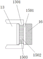
FIG. 6 is a front view of the rubber ring of the present invention;
wherein: 1 liquid storage cavity, 2 platforms, 3 object carrying plates, 4 reflux grooves, 5 filtering and impurity removing mechanisms, 501 first impurity removing cavity, 502 second impurity removing cavity, 503 motor, 504 reciprocating screw rod, 505 vertical frame, 506 reciprocating scraping blade, 507 brush hair, 508 first downcomer, 509 second downcomer, 510 third downcomer, 511 screen, 512 blow-off pipe, 6 recovery box, 7 liquid inlet, 8 liquid pump, 9 liquid outlet pipe, 10 rotary table, 11 bracket, 12 motor, 13 liquid spraying cavity, 1301 clamping key, 14 rotary shaft, 15 rotary table, 1501 clamping ring, 1502 rubber ring, 1503 aluminum sheet, 16 grinding disc, 17 through hole, 18 liquid outlet, 19 control valve, 20 feet, 21 observation strip, 22 water guide plate and 23 blocking edge.
The specific implementation mode is as follows:
in order to make the technical means, the creation characteristics, the achievement purposes and the effects of the invention easy to understand, the invention is further explained below by combining the specific drawings.
Example 1: as shown in fig. 1-3, a shaping and polishing device for die castings comprises a liquid storage cavity 1, a water guide plate 22 is obliquely arranged at the bottom of an inner cavity of the liquid storage cavity 1, four groups of support legs 20 are fixedly arranged at the bottom of the liquid storage cavity 1, a platform 2 is fixedly arranged at the top of the liquid storage cavity 1, an object stage 3 is fixedly connected at the top of the platform 2, flanges 23 are fixedly connected at the tops of four sides of the object stage 3, a rotary table 10 is fixedly arranged at the top of the left side of the liquid storage cavity 1, a bracket 11 is fixedly connected at the top of the rotary table 10, a motor 12 and a liquid spraying cavity 13 are fixedly arranged on the bracket 11, a rotary shaft 14 is fixedly connected at the right side of the motor 12, a rotary table 15 is fixedly connected at the left side wall of the liquid spraying cavity 13, the rotary table 15 is movably clamped with the right wall of the liquid spraying cavity, all run through on mill 16 and the carousel 15 and seted up a plurality of through-holes 17, the bottom fixedly connected with drain pipe 9 of hydrojet chamber 13, drain pipe 9 run through bracket 11 and revolving stage 10 and stretch into the inner chamber bottom in stock solution chamber 1, the upper portion fixed mounting of drain pipe 9 has drawing liquid pump 8, it has run through the inner chamber intercommunication of seting up reflux groove 4 and stock solution chamber 1 from top to bottom on objective table 3 and the platform 2, fixed mounting has screen cloth 5 in the inner chamber in stock solution chamber 1, screen cloth 5 is installed in the bottom of reflux groove 4, the left side top fixed mounting in stock solution chamber 1 has inlet 7, the left side bottom fixed mounting in stock solution chamber 1 has liquid outlet 18, the bottom fixed mounting of liquid outlet 18 has control valve 19.
Example 2: as shown in fig. 1-4, a shaping and polishing device for die castings comprises a liquid storage cavity 1, a water guide plate 22 is obliquely arranged at the bottom of an inner cavity of the liquid storage cavity 1, four groups of support legs 20 are fixedly arranged at the bottom of the liquid storage cavity 1, an observation strip 21 is arranged on the side wall of the liquid storage cavity 1, a platform 2 is fixedly arranged at the top of the liquid storage cavity 1, an objective table 3 is fixedly connected to the top of the platform 2, flanges 23 are fixedly connected to the tops of four sides of the objective table 3, a rotary table 10 is fixedly arranged at the top of the left side of the liquid storage cavity 1, a bracket 11 is fixedly connected to the top of the rotary table 10, a motor 12 and a liquid spraying cavity 13 are fixedly arranged on the bracket 11, a rotating shaft 14 is fixedly connected to the right side of the motor 12, a rotary table 15 is fixedly connected to the left side wall of the liquid spraying cavity 13, the both sides fixedly connected with rand 1501 of carousel 15, rand 1501 and card key 1301 activity joint, the lateral wall fixedly connected with rubber circle 1502 of carousel 15, it has water to fill in the inner chamber of rubber circle 1502, a plurality of aluminum sheets 1503 of the outer wall equidistance fixedly connected with of rubber circle 1502, the right wall activity joint of carousel 15 and hydrojet chamber 13, the right side fixedly connected with mill 16 of carousel 15, all run through on mill 16 and the carousel 15 and seted up a plurality of through-holes 17, the bottom fixedly connected with drain pipe 9 of hydrojet chamber 13, drain pipe 9 runs through bracket 11 and revolving stage 10 and stretches into the inner chamber bottom in stock solution chamber 1, the upper portion fixedly mounted of drain pipe 9 has drawing liquid pump 8, the inner chamber intercommunication of seting up reflux groove 4 and stock solution chamber 1 has been run through from top to bottom on objective table 3 and the platform 2, fixed mounting has screen cloth 5 in the inner chamber in stock solution chamber 1, the screen cloth 5 is installed in the bottom of backwash tank 4, the slope of screen cloth 5 sets up, the right side fixed mounting in stock solution chamber 1 has recovery box 6, the right side of screen cloth 5 stretches into in retrieving box 6, the left side top fixed mounting in stock solution chamber 1 has inlet 7, the left side bottom fixed mounting in stock solution chamber 1 has liquid outlet 18, the bottom fixed mounting of liquid outlet 18 has control valve 19.
The foregoing shows and describes the general principles and broad features of the present invention and advantages thereof. It will be understood by those skilled in the art that the present invention is not limited to the embodiments described above, which are described in the specification and illustrated only to illustrate the principle of the present invention, but that various changes and modifications may be made therein without departing from the spirit and scope of the present invention, which fall within the scope of the invention as claimed. The scope of the invention is defined by the appended claims and equivalents thereof.
Claims (7)
1. The utility model provides a plastic grinding device of die casting, includes stock solution chamber (1), its characterized in that: the top fixed mounting of stock solution chamber (1) has platform (2), the top fixedly connected with objective table (3) of platform (2), the left side top fixed mounting of stock solution chamber (1) has revolving stage (10), the top fixedly connected with bracket (11) of revolving stage (10), fixed mounting has motor (12) and hydrojet chamber (13) on bracket (11), the right side fixedly connected with pivot (14) of motor (12), pivot (14) run through the left side lateral wall fixedly connected with carousel (15) of hydrojet chamber (13), carousel (15) and the right wall activity joint of hydrojet chamber (13), the right side fixedly connected with mill (16) of carousel (15), the right side of hydrojet chamber (13) is provided with card key (1301), the both sides fixedly connected with rand (1501) of carousel (15), rand (1501) and card key (1301) activity joint, the side wall of the turntable (15) is fixedly connected with a rubber ring (1502), the inner cavity of the rubber ring (1502) is filled with water, and the outer wall of the rubber ring (1502) is fixedly connected with a plurality of aluminum sheets (1503) at equal intervals;
all run through on mill (16) and carousel (15) and seted up a plurality of through-holes (17), the bottom fixedly connected with drain pipe (9) of hydrojet chamber (13), drain pipe (9) run through bracket (11) and revolving stage (10) and stretch into the inner chamber bottom in stock solution chamber (1), the upper portion fixed mounting of drain pipe (9) has drawing liquid pump (8), run through the inner chamber intercommunication of seting up reflux groove (4) and stock solution chamber (1) from top to bottom on objective table (3) and platform (2), fixed mounting has screen cloth (5) in the inner chamber in stock solution chamber (1), the bottom in reflux groove (4) is installed in screen cloth (5), the left side top fixed mounting of stock solution chamber (1) has inlet (7), the left side bottom fixed mounting of stock solution chamber (1) has liquid outlet (18).
2. The die casting dressing apparatus of claim 1, wherein: the screen cloth (5) slope sets up, the right side fixed mounting of stock solution chamber (1) has recovery box (6), the right side of screen cloth (5) stretches into in retrieving box (6).
3. The die casting dressing apparatus of claim 1, wherein: and a control valve (19) is fixedly arranged at the bottom of the liquid outlet (18).
4. The die casting dressing apparatus of claim 1, wherein: the bottom of the inner cavity of the liquid storage cavity (1) is obliquely provided with a water guide plate (22).
5. The die casting dressing apparatus of claim 1, wherein: an observation strip (21) is arranged on the side wall of the liquid storage cavity (1).
6. The die casting dressing apparatus of claim 1, wherein: four sides of the object stage (3) are fixedly connected with flanges (23).
7. The die casting dressing apparatus of claim 1, wherein: four groups of support legs (20) are fixedly arranged at the bottom of the liquid storage cavity (1).
Priority Applications (1)
| Application Number | Priority Date | Filing Date | Title |
|---|---|---|---|
| CN201910406951.1A CN110253386B (en) | 2019-05-15 | 2019-05-15 | Shaping and polishing device for die castings |
Applications Claiming Priority (1)
| Application Number | Priority Date | Filing Date | Title |
|---|---|---|---|
| CN201910406951.1A CN110253386B (en) | 2019-05-15 | 2019-05-15 | Shaping and polishing device for die castings |
Publications (2)
| Publication Number | Publication Date |
|---|---|
| CN110253386A CN110253386A (en) | 2019-09-20 |
| CN110253386B true CN110253386B (en) | 2020-06-09 |
Family
ID=67914751
Family Applications (1)
| Application Number | Title | Priority Date | Filing Date |
|---|---|---|---|
| CN201910406951.1A Active CN110253386B (en) | 2019-05-15 | 2019-05-15 | Shaping and polishing device for die castings |
Country Status (1)
| Country | Link |
|---|---|
| CN (1) | CN110253386B (en) |
Families Citing this family (3)
| Publication number | Priority date | Publication date | Assignee | Title |
|---|---|---|---|---|
| CN111716186A (en) * | 2020-06-11 | 2020-09-29 | 张亮 | Shaping and polishing device for die castings |
| CN112296876B (en) * | 2020-10-13 | 2023-05-02 | 重庆泊利玺智能科技有限公司 | A polisher that is used for polishing tubular product and has unilateral chamfer function of polishing |
| CN113458916A (en) * | 2021-08-02 | 2021-10-01 | 安徽索立德铸业有限公司 | Dustless processingequipment that polishes of work piece |
Citations (1)
| Publication number | Priority date | Publication date | Assignee | Title |
|---|---|---|---|---|
| CN204621808U (en) * | 2015-02-12 | 2015-09-09 | 肇庆市鼎臣永磁设备有限公司 | A kind of grinding magnetic shoe material is grinding head dedicated |
Family Cites Families (5)
| Publication number | Priority date | Publication date | Assignee | Title |
|---|---|---|---|---|
| JPH05177535A (en) * | 1992-01-09 | 1993-07-20 | Toshiba Corp | Method and device for polishing |
| JPH06312375A (en) * | 1993-04-28 | 1994-11-08 | Noritake Dia Kk | Manufacture of resin bond wheel having vent hole structure and grinding method using the same |
| TWM263187U (en) * | 2004-07-28 | 2005-05-01 | Mu-Chuan Lin | Heat dissipation structure of emery wheel plate of grinder |
| CN105666330A (en) * | 2016-04-13 | 2016-06-15 | 湘潭大学 | Novel grinding system |
| CN206305901U (en) * | 2016-11-10 | 2017-07-07 | 天津市昊航复合管业有限公司 | Temperature quickly cooling device in a kind of composite steel tube bruting process |
-
2019
- 2019-05-15 CN CN201910406951.1A patent/CN110253386B/en active Active
Patent Citations (1)
| Publication number | Priority date | Publication date | Assignee | Title |
|---|---|---|---|---|
| CN204621808U (en) * | 2015-02-12 | 2015-09-09 | 肇庆市鼎臣永磁设备有限公司 | A kind of grinding magnetic shoe material is grinding head dedicated |
Also Published As
| Publication number | Publication date |
|---|---|
| CN110253386A (en) | 2019-09-20 |
Similar Documents
| Publication | Publication Date | Title |
|---|---|---|
| CN110253386B (en) | Shaping and polishing device for die castings | |
| CN107378624A (en) | A kind of gear cutting machine sewage collection system | |
| CN210909193U (en) | Intelligent cutting device for metal section | |
| CN205309945U (en) | Mechanical product abrasive machining processing system | |
| CN212193838U (en) | Injection mold convenient to it is clean | |
| CN205764223U (en) | A kind of aluminium section bar processing unit (plant) with antirust function | |
| CN110253365B (en) | Die casting shaping device with polishing liquid filtering and recycling functions | |
| CN216327609U (en) | Cooling device for grinder | |
| CN208961787U (en) | A kind of grinder cooling device | |
| CN207593489U (en) | A kind of steel ingot production and processing grinding device | |
| CN209439938U (en) | A kind of stone material production waste water filtering mechanism of grinding device | |
| CN111716186A (en) | Shaping and polishing device for die castings | |
| CN114833584B (en) | Numerical control spinning device capable of processing large-batch copper kettles and application method | |
| CN113798328B (en) | Method and device for improving cleaning capacity of roller surface of finishing machine | |
| CN215824229U (en) | Cooling mechanism of five metals die casting machine | |
| CN213196771U (en) | Cylindrical grinder is used in bearing production | |
| CN210161292U (en) | Packaging film cooling spray set | |
| CN211191926U (en) | Water cooling device for hardware die castings | |
| CN221290560U (en) | Surface polishing device for balancing weight production | |
| CN212404046U (en) | Energy-concerving and environment-protective type metal coolant liquid preparation system | |
| CN210254194U (en) | Five metals foundry goods sand removal device | |
| CN207120054U (en) | A kind of gear cutting machine sewage collection system | |
| CN205057802U (en) | Processing apparatus is supplied with to machinery grinding fluid | |
| CN218785627U (en) | Knife sharpening device is used in chinese-medicinal material processing | |
| CN219194747U (en) | Fluorouracil effluent treatment plant |
Legal Events
| Date | Code | Title | Description |
|---|---|---|---|
| PB01 | Publication | ||
| PB01 | Publication | ||
| SE01 | Entry into force of request for substantive examination | ||
| SE01 | Entry into force of request for substantive examination | ||
| GR01 | Patent grant | ||
| GR01 | Patent grant |