CN110251341B - Hepatobiliary surgery is with nursing device with drainage function - Google Patents
Hepatobiliary surgery is with nursing device with drainage function Download PDFInfo
- Publication number
- CN110251341B CN110251341B CN201910626260.2A CN201910626260A CN110251341B CN 110251341 B CN110251341 B CN 110251341B CN 201910626260 A CN201910626260 A CN 201910626260A CN 110251341 B CN110251341 B CN 110251341B
- Authority
- CN
- China
- Prior art keywords
- liquid
- pipe
- side wall
- outer side
- communicated
- Prior art date
- Legal status (The legal status is an assumption and is not a legal conclusion. Google has not performed a legal analysis and makes no representation as to the accuracy of the status listed.)
- Expired - Fee Related
Links
Images


Classifications
-
- A—HUMAN NECESSITIES
- A61—MEDICAL OR VETERINARY SCIENCE; HYGIENE
- A61G—TRANSPORT, PERSONAL CONVEYANCES, OR ACCOMMODATION SPECIALLY ADAPTED FOR PATIENTS OR DISABLED PERSONS; OPERATING TABLES OR CHAIRS; CHAIRS FOR DENTISTRY; FUNERAL DEVICES
- A61G12/00—Accommodation for nursing, e.g. in hospitals, not covered by groups A61G1/00 - A61G11/00, e.g. trolleys for transport of medicaments or food; Prescription lists
-
- A61M1/0023—
-
- A61M1/0058—
Abstract
The invention discloses a hepatobiliary surgery nursing device with a drainage function, which belongs to the field of medical instruments and comprises a carrying plate, wherein a liquid accumulation tank is fixedly arranged on the upper surface of the carrying plate, the upper surface of the liquid accumulation tank is communicated with one end of an exhaust tube, the other end of the exhaust tube is communicated with one end of an exhaust tube, a rubber ring is arranged in the exhaust tube, the rubber ring is fixedly arranged at one end of a connecting rod, the outer side wall of the connecting rod is sleeved in a fixing sleeve, and the fixing sleeve is embedded at the other end of the exhaust tube; through the setting of hydrops jar, exhaust tube, pump bowl, liquid suction pipe, liquid pumping head and instrument platform, the nursing staff also can carry out the drainage operation when nursing the patient, places the liquid pumping head in the patient internally, utilizes the pump bowl to bleed and produces the negative pressure and take out the internal hydrops of patient to reach the effect of drainage, the nursing is gone on in step with the drainage, has promoted treatment effeciency.
Description
Technical Field
The invention belongs to the technical field of medical instruments, and particularly relates to a hepatobiliary surgery nursing device with a drainage function.
Background
The hepatobiliary surgery mainly researches hepatocellular carcinoma, hepatobiliary calculus, posthepatitic cirrhosis and acute hepatic failure caused by severe hepatitis, which are major diseases seriously threatening the health of Chinese people, and can ensure that various hepatobiliary disease patients can be treated by an optimized system along with the establishment, perfection and popularization of a multidisciplinary expert team taking the diseases as the basis and a combined diagnosis and treatment mechanism.
Original nursing device function singleness exists certain inconvenience in the use, does not possess the function of drainage, leads to the patient to need drainage equipment in addition when carrying out liver and gall treatment, and current drainage equipment anti-reflux effect is relatively poor, causes the hydrops backward flow easily, leads to the patient to need carry out the secondary treatment, has lengthened patient's treatment time.
Disclosure of Invention
The invention aims to provide a hepatobiliary surgery nursing device with a drainage function, so as to solve the problems in the background technology.
In order to achieve the purpose, the invention provides the following technical scheme:
a nursing device with a drainage function for hepatobiliary surgery comprises a carrying plate, wherein a liquid accumulation tank is fixedly arranged on the upper surface of the carrying plate, the upper surface of the liquid accumulation tank is communicated with one end of an exhaust tube, the other end of the exhaust tube is communicated with one end of the exhaust tube, a rubber ring is arranged inside the exhaust tube and fixedly arranged at one end of a connecting rod, the outer side wall of the connecting rod is sleeved in a fixed sleeve, the fixed sleeve is embedded at the other end of the exhaust tube, one end of the connecting rod, which is positioned at the outer side of the exhaust tube, is fixedly connected with one side surface of a fixed plate, one side surface of the fixed plate is fixedly connected with the telescopic ends of two electric push rods a respectively, the two electric push rods a are fixedly arranged on the outer side wall of the exhaust tube, the upper surface of the liquid accumulation tank is also communicated with one end of a liquid pumping tube, and two backflow preventing channels are respectively provided with a valve ball b and an embedded block, the embedded block is fixedly arranged in the backflow preventing channel, the embedded block is fixedly connected with the outer side wall of the sliding sleeve, the sliding sleeve is internally sleeved with a sliding rod, one end of the sliding rod is fixedly connected with the valve ball b, the other end of the sliding rod is fixedly provided with a conical block, the outer side wall of the sliding rod is sleeved with a spring b, the two ends of the spring b are respectively and fixedly connected with the opposite surfaces of the conical block and the sliding sleeve, the other end of the liquid pumping pipe is detachably connected with a liquid pumping head, the outer side wall of the liquid pumping head is fixedly provided with a rubber ring, one side of the liquid accumulating tank is provided with a tool table, the other end of the liquid accumulating tank is provided with a water tank, the upper surface of the water tank is fixedly provided with a water pump, the water inlet of the water pump is communicated with the, the other end and the annular pipe of flexible hose are linked together, the inside wall of annular pipe is through three dead lever and connecting block fixed connection, and the connecting block is fixed to be located electric putter b's flexible and serve, electric putter b fixed mounting is at the inboard top of hydrops jar, electric putter an, water pump and electric putter b respectively with external power supply electric connection.
Preferably, the outer side wall of the air pumping cylinder is also communicated with an exhaust pipe.
Preferably, a fixed block is fixedly arranged in the exhaust pipe, and the upper surface of the fixed block is elastically connected with a valve ball a through a spring a.
Preferably, the equal fixed mounting of instrument stand and water tank is in the upper surface of objective plate, the pull is connected with the article steamer tray in the instrument stand, and has seted up the cotton swab groove in the article steamer tray, the standing groove has been seted up in the front of instrument stand, and has placed the refuse case in the standing groove.
Preferably, the outer side wall of the annular pipe is provided with a plurality of spray heads.
Preferably, the outer side wall of the liquid accumulation tank is provided with a transparent window, and the transparent window is provided with scales.
Preferably, a sealing plug is arranged at the bottom of the liquid accumulation tank.
Preferably, the lower surface of the carrying plate is fixedly connected with a moving wheel through four pillars.
Compared with the prior art, the invention has the beneficial effects that:
through the setting of hydrops jar, exhaust tube, pump bowl, liquid suction pipe, liquid pumping head and instrument platform, the nursing staff also can carry out the drainage operation when nursing the patient, places the liquid pumping head in the patient internally, utilizes the pump bowl to bleed and produces the negative pressure and take out the internal hydrops of patient to reach the effect of drainage, the nursing is gone on in step with the drainage, has promoted treatment effeciency.
Through built-in piece, the sliding sleeve, the slide bar, valve ball b, conical block and spring b's setting, when taking out the intraductal liquid work that takes out of drawing, the liquid flow extrusion conical block breaks away from and prevents the backflow passageway and makes the drawing liquid go on smoothly this moment, after the drawing liquid stops, extrude conical block and prevent the backflow passageway laminating under spring b's spring action this moment, close the liquid suction pipe, the liquid suction pipe also can be plugged up to valve ball b simultaneously, improve and prevent the backflow effect, moreover, the steam generator is simple in structure, and the treatment time of patient is shortened.
Through the setting of water tank, water pump, inlet tube, outlet pipe, expansion hose, ring pipe and electric putter b, if need wash the during operation in to the hydrops jar, start the inside water liquid of water pump extraction water tank and spout through the shower nozzle on the ring pipe to wash the inside wall of hydrops jar, avoid the hydrops to be attached to in the hydrops jar, electric putter b work can drive the ring pipe and reciprocate simultaneously, improves the flushing effect.
Through the setting of blast pipe, fixed block, spring a and valve ball an, when needing the exhaust in the exhaust column, the rubber circle moves forward makes the increase of blast pipe internal gas pressure, promotes valve ball an rebound and opens the blast pipe to with gas escape, can utilize the negative pressure effect smoothly to take out the internal hydrops of patient.
Drawings
FIG. 1 is a schematic structural view of the present invention;
FIG. 2 is a schematic view of the interior of the effusion cell in accordance with the present invention;
FIG. 3 is a schematic top view of the annular tube of the present invention;
FIG. 4 is a schematic view of the interior of the drawer according to the present invention;
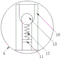
FIG. 5 is an enlarged schematic view of the structure of the present invention at A;
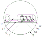
FIG. 6 is an enlarged schematic view of the present invention at B.
In the figure: 1. a loading plate; 2. a liquid accumulation tank; 3. an air exhaust pipe; 4. an air pumping cylinder; 5. a rubber ring; 6. a connecting rod; 7. fixing a sleeve; 8. a fixing plate; 9. an electric push rod a; 10. an exhaust pipe; 11. a fixed block; 12. a spring a; 13. a valve ball a; 14. a liquid pumping pipe; 15. a built-in block; 16. a sliding sleeve; 17. a slide bar; 18. a valve ball b; 19. a conical block; 20. a spring b; 21. a liquid pumping head; 22. a rubber ring; 23. a tool table; 24. a drawer; 25. a cotton swab groove; 26. a waste bin; 27. a water tank; 28. a water pump; 29. a water inlet pipe; 30. a water outlet pipe; 31. a flexible hose; 32. an annular tube; 33. fixing the rod; 34. connecting blocks; 35. an electric push rod b; 36. a spray head; 37. a transparent window; 38. a sealing plug; 39. a pillar; 40. the wheel is moved.
Detailed Description
The technical solutions in the embodiments of the present invention will be clearly and completely described below with reference to the drawings in the embodiments of the present invention, and it is obvious that the described embodiments are only a part of the embodiments of the present invention, and not all of the embodiments. All other embodiments, which can be derived by a person skilled in the art from the embodiments given herein without making any creative effort, shall fall within the protection scope of the present invention.
Referring to fig. 1-6, the present invention provides a hepatobiliary surgery nursing device with drainage function, comprising a carrying plate 1, wherein a fluid accumulation tank 2 is fixedly installed on the upper surface of the carrying plate 1, the upper surface of the fluid accumulation tank 2 is communicated with one end of an air pumping tube 3, the other end of the air pumping tube 3 is communicated with one end of an air pumping tube 4, a rubber ring 5 is installed inside the air pumping tube 4, the rubber ring 5 is fixedly installed at one end of a connecting rod 6, the outer side wall of the connecting rod 6 is sleeved in a fixing sleeve 7, the fixing sleeve 7 is embedded at the other end of the air pumping tube 4, one end of the connecting rod 6 located outside the air pumping tube 4 is fixedly connected with one side surface of a fixing plate 8, one side surface of the fixing plate 8 is fixedly connected with the telescopic ends of two electric push rods a9, the two electric push rods a9 are both fixedly installed on the outer side wall of the air pumping tube 4, the, two backflow prevention channels are arranged inside the liquid pumping pipe 14, a valve ball b18 and an internal block 15 are respectively arranged in the two backflow prevention channels, the internal block 15 is fixedly arranged in the backflow prevention channels, the internal block 15 is fixedly connected with the outer side wall of the sliding sleeve 16, a sliding rod 17 is sleeved in the sliding sleeve 16, one end of the sliding rod 17 is fixedly connected with a valve ball b18, the other end of the sliding rod 17 is fixedly provided with a conical block 19, the outer side wall of the sliding rod 17 is sleeved with a spring b20, two ends of the spring b20 are respectively fixedly connected with the opposite surfaces of the conical block 19 and the sliding sleeve 16, the other end of the liquid pumping pipe 14 is detachably connected with a liquid pumping head 21, the outer side wall of the liquid pumping head 21 is fixedly provided with a rubber ring 22, one side of the liquid accumulation tank 2 is provided with a tool table 23, the other end of the liquid accumulation tank 2 is provided with a water tank 27, the upper surface of the water, the delivery port of water pump 28 is linked together through outlet pipe 30 and the one end of flexible hose 31 in the hydrops jar 2, the other end and the ring pipe 32 of flexible hose 31 are linked together, the inside wall of ring pipe 32 is through three dead lever 33 and connecting block 34 fixed connection, and connecting block 34 is fixed to be located electric putter b 35's flexible end, electric putter b35 fixed mounting is at the inboard top of hydrops jar 2, electric putter a9, water pump 28 and electric putter b35 respectively with external power supply electric connection.
In the embodiment, through the arrangement of the accumulated liquid tank 2, the exhaust tube 3, the exhaust cylinder 4, the liquid pumping tube 14, the liquid pumping head 21 and the tool table 23, a nursing staff can perform drainage operation while nursing a patient, the liquid pumping head 21 is placed in the patient, negative pressure generated by air pumping of the exhaust cylinder 4 is utilized to pump out accumulated liquid in the patient, so that drainage effect is achieved, nursing and drainage are performed synchronously, treatment efficiency is improved, through the arrangement of the built-in block 15, the sliding sleeve 16, the sliding rod 17, the valve ball b18, the conical block 19 and the spring b20, when liquid pumping work is performed in the liquid pumping tube 14, liquid flows to extrude the conical block 19 to be separated from the backflow prevention channel, so that liquid pumping can be performed smoothly, after liquid pumping is stopped, the backflow prevention block 19 is extruded under the elastic action of the spring b20 to be attached to the backflow prevention channel, the liquid pumping tube 14 is closed, and the valve ball b18 can also block the liquid pumping tube 14, improve the anti-backflow effect, the structure is simple, the treatment time of the patient is reduced, through the arrangement of the water tank 27, the water pump 28, the water inlet pipe 29, the water outlet pipe 30, the telescopic hose 31, the annular pipe 32 and the electric push rod b35, if the liquid accumulation tank 2 needs to be cleaned, the water pump 28 is started to pump the water in the water tank 27 and spray the water out through the spray head 36 on the annular pipe 32, thereby the inner side wall of the liquid accumulation tank 2 is washed, the liquid accumulation is prevented from being attached to the liquid accumulation tank 2, meanwhile, the electric push rod b35 can drive the annular pipe 32 to move up and down, the washing effect is improved, through the arrangement of the exhaust pipe 10, the fixed block 11, the spring a12 and the valve ball a13, when the exhaust is needed in the exhaust cylinder 4, the rubber ring 5 moves forward to increase the pressure of the exhaust pipe 10, the valve ball a13 is pushed to move upward and opens the exhaust pipe 10, through electric putter a 9's power effect to can accomplish the work of bleeding of the inner loop of aspiration cylinder 4 automatically, can dismantle the one end of connection at liquid suction pipe 14 through with liquid head 21, thereby can demolish liquid head 21, avoid used repeatedly to lead to cross infection, through the setting of rubber ring 22, thereby be convenient for cover liquid head 21 adhesion at patient's wound surface, avoid liquid head 21 to take place to break away from.
Specifically, the outer side wall of the air pumping cylinder 4 is also communicated with an exhaust pipe 10, and the exhaust pipe 10 is arranged, so that redundant gas in the air pumping cylinder 4 can be conveniently exhausted.
Specifically, a fixed block 11 is fixedly arranged in the exhaust pipe 10, and the upper surface of the fixed block 11 is elastically connected with a valve ball a13 through a spring a 12; through the arrangement of the fixed block 11, the spring a12 and the valve ball a13, the valve ball a13 is pushed to move when gas is exhausted, so that the exhaust pipe 10 is opened, and after the gas is exhausted, the valve ball a13 can close the exhaust pipe 10 under the action of the tension of the spring a12 and the gravity of the valve ball a13, so that subsequent liquid pumping work can be conveniently carried out.
Specifically, both the tool table 23 and the water tank 27 are fixedly mounted on the upper surface of the object carrying plate 1, the tool table 23 is connected with a drawer 24 in a drawing manner, a cotton swab groove 25 is formed in the drawer 24, a placing groove is formed in the front surface of the tool table 23, and a waste bin 26 is placed in the placing groove; through the setting of drawer 24 to can place the required instrument of nursing, and the required cotton swab of nursing etc. can be placed in the setting of cotton swab groove 25, through the setting of dustbin 26, thereby be convenient for put in the used wastes material of nursing in-process, improve the clean and tidy of surrounding environment.
Specifically, the outer side wall of the annular pipe 32 is provided with a plurality of spray heads 36; through the setting of shower nozzle 36 to the water liquid of being convenient for spouts from the ring pipe 32, improves the washing effect to the hydrops jar 2 inside wall.
Specifically, the outer side wall of the liquid accumulation tank 2 is provided with a transparent window 37, and the transparent window 37 is provided with scales; through the setting of transparent window 37 and scale to the hydrops volume of drawing out in the hydrops jar 2 is connected to the nursing staff directly perceived.
Specifically, the bottom of the liquid accumulation tank 2 is provided with a sealing plug 38; through the arrangement of the sealing plug 38, the accumulated liquid pumped out from the accumulated liquid tank 2 is convenient to discharge.
Specifically, the lower surface of the object carrying plate 1 is fixedly connected with a moving wheel 40 through four support posts 39; through the setting that removes wheel 40 to be convenient for remove the whole, convenient and fast more in the use.
It should be noted that:
the model of the electric push rod a9 and the model of the electric push rod b35 can be hydj 24-300; the water pump 28 may be specifically NMDP 41.
The working principle and the using process of the invention are as follows:
after the device is installed, the liquid pumping head 21 is firstly placed in a patient, the electric push rod a9 is started to work to push the fixed plate 8 to move, the fixed plate 8 moves to drive the rubber ring 5 to move through the connecting rod 6, negative pressure generated by air pumping of the air pumping cylinder 4 is utilized to pump accumulated liquid in the patient, so that the drainage effect is achieved, nursing and drainage are synchronously performed, the treatment efficiency is improved, when liquid pumping work is performed in the liquid pumping pipe 14, liquid flows to press the conical block 19 to be separated from the backflow prevention channel, so that liquid pumping can be smoothly performed, when air needs to be exhausted in the air pumping cylinder 4, the rubber ring 5 moves forwards to increase the air pressure in the exhaust pipe 10, the valve ball a13 is pushed to move upwards and open the exhaust pipe 10, so that air is exhausted, the backflow prevention liquid in the patient can be pumped out smoothly by utilizing the negative pressure effect, when liquid pumping is stopped, the conical block 19 is pressed under the elastic force of the, closing the liquid pumping tube 14, and simultaneously the valve ball b18 can also block the liquid pumping tube 14, thereby improving the anti-backflow effect, the structure is simple, the treatment time of the patient is reduced, when the air pumping tube 4 pumps air to generate negative pressure, the exhaust pipe 10 is closed and the liquid pumping tube 14 is opened, when the air pumping tube 4 exhausts air, the liquid pumping tube 14 is closed and the exhaust pipe 10 is opened, thereby completely ensuring the smooth proceeding of the liquid pumping work, when the liquid accumulation tank 2 needs to be cleaned, the water pump 28 is started to pump the water liquid in the water tank 27 and is sprayed out through the spray head 36 on the annular tube 32, thereby flushing the inner side wall of the liquid accumulation tank 2, preventing the liquid accumulation from attaching in the liquid accumulation tank 2, simultaneously the electric push rod b35 works to drive the annular tube 32 to move up and down, thereby improving the flushing effect, the liquid pumping head 21 can be detachably connected at one end of the liquid pumping tube, through the arrangement of the rubber ring 22, the liquid extracting head 21 is convenient to be adhered to the surface of a wound of a patient, and the liquid extracting head 21 is prevented from being separated.
Although embodiments of the present invention have been shown and described, it will be appreciated by those skilled in the art that changes, modifications, substitutions and alterations can be made in these embodiments without departing from the principles and spirit of the invention, the scope of which is defined in the appended claims and their equivalents.
Claims (6)
1. The utility model provides a hepatobiliary surgery is with nursing device with drainage function, is including carrying thing board (1), its characterized in that: the upper surface of the object carrying plate (1) is fixedly provided with an accumulated liquid tank (2), the upper surface of the accumulated liquid tank (2) is communicated with one end of an air pumping pipe (3), the other end of the air pumping pipe (3) is communicated with one end of the air pumping pipe (4), a rubber ring (5) is arranged inside the air pumping pipe (4), the rubber ring (5) is fixedly arranged at one end of a connecting rod (6), the outer side wall of the connecting rod (6) is sleeved in a fixing sleeve (7), the fixing sleeve (7) is embedded at the other end of the air pumping pipe (4), one end of the connecting rod (6) positioned outside the air pumping pipe (4) is fixedly connected with one side surface of a fixing plate (8), one side surface of the fixing plate (8) is respectively fixedly connected with the telescopic ends of two electric push rods a (9), the two electric push rods a (9) are fixedly arranged on the outer side wall of the air pumping pipe (4), the upper surface of the accumulated liquid tank (2) is also communicated with one end, the anti-backflow device is characterized in that two anti-backflow channels are arranged inside the liquid pumping pipe (14), a valve ball b (18) and a built-in block (15) are respectively arranged in the two anti-backflow channels, the built-in block (15) is fixedly arranged in the anti-backflow channels, the built-in block (15) is fixedly connected with the outer side wall of the sliding sleeve (16), a sliding rod (17) is sleeved in the sliding sleeve (16), one end of the sliding rod (17) is fixedly connected with the valve ball b (18), the other end of the sliding rod (17) is fixedly provided with a conical block (19), the outer side wall of the sliding rod (17) is sleeved with a spring b (20), two ends of the spring b (20) are respectively fixedly connected with the opposite surfaces of the conical block (19) and the sliding sleeve (16), the other end of the liquid pumping pipe (14) is detachably connected with a liquid pumping head (21), the outer side wall of the liquid pumping head (21) is fixedly provided with a rubber ring (22), the other end of the liquid accumulation tank (2) is provided with a water tank (27), the upper surface of the water tank (27) is fixedly provided with a water pump (28), and the water inlet of the water pump (28) is communicated with the bottom of the water tank (27) through a water inlet pipe (29), the water outlet of the water pump (28) is communicated with one end of a flexible hose (31) in the liquid accumulation tank (2) through a water outlet pipe (30), the other end of the telescopic hose (31) is communicated with an annular pipe (32), the inner side wall of the annular pipe (32) is fixedly connected with a connecting block (34) through three fixing rods (33), and the connecting block (34) is fixedly arranged on the telescopic end of the electric push rod b (35), the electric push rod b (35) is fixedly arranged at the top of the inner side of the liquid accumulation tank (2), the electric push rod a (9), the water pump (28) and the electric push rod b (35) are respectively electrically connected with an external power supply;
the outer side wall of the air pumping cylinder (4) is also communicated with an exhaust pipe (10);
the exhaust pipe (10) internal fixation is equipped with fixed block (11), the upper surface of fixed block (11) has valve ball a (13) through spring a (12) elastic connection.
2. The surgical nursing device with drainage function for liver and gall bladder of claim 1, wherein: the utility model discloses a portable tool table, including instrument platform (23), water tank (27), drawing are connected with article drawer (24) in instrument platform (23), and have seted up cotton swab groove (25) in article drawer (24), the standing groove has been seted up in the front of instrument platform (23), and has placed waste bin (26) in the standing groove in the upper surface of objective plate (1).
3. The surgical nursing device with drainage function for liver and gall bladder of claim 1, wherein: the outer side wall of the annular pipe (32) is provided with a plurality of spray heads (36).
4. The surgical nursing device with drainage function for liver and gall bladder of claim 1, wherein: the outer side wall of the liquid accumulation tank (2) is provided with a transparent window (37), and the transparent window (37) is provided with scales.
5. The surgical nursing device with drainage function for liver and gall bladder of claim 1, wherein: and a sealing plug (38) is arranged at the bottom of the liquid accumulation tank (2).
6. The surgical nursing device with drainage function for liver and gall bladder of claim 1, wherein: the lower surface of the object carrying plate (1) is fixedly connected with a moving wheel (40) through four support columns (39).
Priority Applications (1)
| Application Number | Priority Date | Filing Date | Title |
|---|---|---|---|
| CN201910626260.2A CN110251341B (en) | 2019-07-11 | 2019-07-11 | Hepatobiliary surgery is with nursing device with drainage function |
Applications Claiming Priority (1)
| Application Number | Priority Date | Filing Date | Title |
|---|---|---|---|
| CN201910626260.2A CN110251341B (en) | 2019-07-11 | 2019-07-11 | Hepatobiliary surgery is with nursing device with drainage function |
Publications (2)
| Publication Number | Publication Date |
|---|---|
| CN110251341A CN110251341A (en) | 2019-09-20 |
| CN110251341B true CN110251341B (en) | 2020-11-27 |
Family
ID=67925600
Family Applications (1)
| Application Number | Title | Priority Date | Filing Date |
|---|---|---|---|
| CN201910626260.2A Expired - Fee Related CN110251341B (en) | 2019-07-11 | 2019-07-11 | Hepatobiliary surgery is with nursing device with drainage function |
Country Status (1)
| Country | Link |
|---|---|
| CN (1) | CN110251341B (en) |
Families Citing this family (2)
| Publication number | Priority date | Publication date | Assignee | Title |
|---|---|---|---|---|
| CN111449617B (en) * | 2020-04-10 | 2023-07-25 | 西安交通大学医学院第二附属医院 | Cystoscope with suction function |
| CN112827975B (en) * | 2021-01-06 | 2022-06-10 | 郑州大学第一附属医院 | Drainage device is used in hepatobiliary surgery nursing |
Citations (9)
| Publication number | Priority date | Publication date | Assignee | Title |
|---|---|---|---|---|
| CN2514840Y (en) * | 2001-10-09 | 2002-10-09 | 刘华 | Thoracico-abdominal puncture continuous liquid aspirator |
| CA2640549A1 (en) * | 2007-10-04 | 2009-04-04 | Dornoch Medical Systems, Inc. | Medical waste fluid collection and disposal system |
| CN201987927U (en) * | 2011-02-24 | 2011-09-28 | 王秀晶 | Negative pressure suction device for internal medicine |
| CN102320431A (en) * | 2011-06-16 | 2012-01-18 | 上海华中药业有限公司 | Novel liquid container tank |
| CN105343943A (en) * | 2015-10-04 | 2016-02-24 | 袁玉香 | Cardiovascular drainage apparatus |
| CN108743376A (en) * | 2018-03-29 | 2018-11-06 | 王冲 | A kind of pharmacy infusion automatic dispensation apparatus |
| CN208199044U (en) * | 2018-05-18 | 2018-12-07 | 缙云县阪喜达包装有限公司 | A kind of liquid packaging machine equipment liquid storage can washing apparatus |
| CN208641368U (en) * | 2017-09-05 | 2019-03-26 | 朱彦红 | A kind of drainage device for liver ascites |
| CN109966573A (en) * | 2019-05-07 | 2019-07-05 | 冯勇 | A kind of medical treatment department of general surgery hepatobiliary drainage device |
Family Cites Families (4)
| Publication number | Priority date | Publication date | Assignee | Title |
|---|---|---|---|---|
| CN2462927Y (en) * | 2001-02-19 | 2001-12-05 | 段荣勤 | Multi-functional portable nursing sputum aspirator |
| CN2715763Y (en) * | 2004-07-08 | 2005-08-10 | 申承华 | Manual negative pressure aspirator |
| CN203090001U (en) * | 2013-01-16 | 2013-07-31 | 郑芳 | Drainage device for cardiology department |
| CN205108204U (en) * | 2015-11-19 | 2016-03-30 | 袁成勇 | Drainage car is washed to health services body surface traumatism |
-
2019
- 2019-07-11 CN CN201910626260.2A patent/CN110251341B/en not_active Expired - Fee Related
Patent Citations (9)
| Publication number | Priority date | Publication date | Assignee | Title |
|---|---|---|---|---|
| CN2514840Y (en) * | 2001-10-09 | 2002-10-09 | 刘华 | Thoracico-abdominal puncture continuous liquid aspirator |
| CA2640549A1 (en) * | 2007-10-04 | 2009-04-04 | Dornoch Medical Systems, Inc. | Medical waste fluid collection and disposal system |
| CN201987927U (en) * | 2011-02-24 | 2011-09-28 | 王秀晶 | Negative pressure suction device for internal medicine |
| CN102320431A (en) * | 2011-06-16 | 2012-01-18 | 上海华中药业有限公司 | Novel liquid container tank |
| CN105343943A (en) * | 2015-10-04 | 2016-02-24 | 袁玉香 | Cardiovascular drainage apparatus |
| CN208641368U (en) * | 2017-09-05 | 2019-03-26 | 朱彦红 | A kind of drainage device for liver ascites |
| CN108743376A (en) * | 2018-03-29 | 2018-11-06 | 王冲 | A kind of pharmacy infusion automatic dispensation apparatus |
| CN208199044U (en) * | 2018-05-18 | 2018-12-07 | 缙云县阪喜达包装有限公司 | A kind of liquid packaging machine equipment liquid storage can washing apparatus |
| CN109966573A (en) * | 2019-05-07 | 2019-07-05 | 冯勇 | A kind of medical treatment department of general surgery hepatobiliary drainage device |
Also Published As
| Publication number | Publication date |
|---|---|
| CN110251341A (en) | 2019-09-20 |
Similar Documents
| Publication | Publication Date | Title |
|---|---|---|
| CN110251341B (en) | Hepatobiliary surgery is with nursing device with drainage function | |
| CN209734643U (en) | Uropoiesis surgery washing unit | |
| CN107243091B (en) | Multifunctional anorectal nursing equipment | |
| CN206355383U (en) | A kind of medical gynecological and obstetrical nursing cleaning device | |
| CN202637353U (en) | Sterilizing vehicle for trauma disposal | |
| CN207203077U (en) | A kind of new urological department male's cleaning sterilizing device | |
| CN212913694U (en) | Debridement device for general surgery department | |
| CN206081029U (en) | Nursing device washs with perineum in gynaecology and obstetrics | |
| CN208726398U (en) | A kind of vagina flusher for gynecological clinic | |
| CN202637165U (en) | Oral-cavity cleaning device | |
| CN206261847U (en) | A kind of new vomiting auxiliary tank | |
| CN207429252U (en) | Flushable ostomy bag | |
| CN211132410U (en) | Wound cleaning device for surgery | |
| CN113041426A (en) | Wound belt cleaning device of waste liquid can be collected in clinical operation of department of general surgery | |
| CN102309812B (en) | Negative-pressure drainage device | |
| CN210844479U (en) | Drainage device for hepatobiliary surgery | |
| CN204864289U (en) | Disposable birth canal flusher | |
| CN214806720U (en) | Multifunctional bedpan convenient for wound irrigation | |
| CN210009409U (en) | Hydrops draw-out device for medical treatment operation | |
| CN218220708U (en) | Drainage device for emergency internal medicine department | |
| CN203815958U (en) | Excrement take-out auxiliary device for department of gastroenterology | |
| CN213374282U (en) | Ear-nose-throat sprayer | |
| CN217645614U (en) | Wound irrigation device | |
| CN203677617U (en) | Disposable water collecting bag used for surgery debridement | |
| CN216169164U (en) | Uropoiesis is washing unit for surgery nursing |
Legal Events
| Date | Code | Title | Description |
|---|---|---|---|
| PB01 | Publication | ||
| PB01 | Publication | ||
| SE01 | Entry into force of request for substantive examination | ||
| SE01 | Entry into force of request for substantive examination | ||
| GR01 | Patent grant | ||
| GR01 | Patent grant | ||
| CF01 | Termination of patent right due to non-payment of annual fee | ||
| CF01 | Termination of patent right due to non-payment of annual fee |
Granted publication date: 20201127 Termination date: 20210711 |