CN110240077B - Constant-speed winch for engineering measurement and using method - Google Patents
Constant-speed winch for engineering measurement and using method Download PDFInfo
- Publication number
- CN110240077B CN110240077B CN201910638625.3A CN201910638625A CN110240077B CN 110240077 B CN110240077 B CN 110240077B CN 201910638625 A CN201910638625 A CN 201910638625A CN 110240077 B CN110240077 B CN 110240077B
- Authority
- CN
- China
- Prior art keywords
- rotating wheel
- motor
- belt
- motor rotating
- small belt
- Prior art date
- Legal status (The legal status is an assumption and is not a legal conclusion. Google has not performed a legal analysis and makes no representation as to the accuracy of the status listed.)
- Expired - Fee Related
Links
Images


Classifications
-
- B—PERFORMING OPERATIONS; TRANSPORTING
- B66—HOISTING; LIFTING; HAULING
- B66D—CAPSTANS; WINCHES; TACKLES, e.g. PULLEY BLOCKS; HOISTS
- B66D1/00—Rope, cable, or chain winding mechanisms; Capstans
- B66D1/02—Driving gear
- B66D1/12—Driving gear incorporating electric motors
-
- B—PERFORMING OPERATIONS; TRANSPORTING
- B66—HOISTING; LIFTING; HAULING
- B66D—CAPSTANS; WINCHES; TACKLES, e.g. PULLEY BLOCKS; HOISTS
- B66D1/00—Rope, cable, or chain winding mechanisms; Capstans
- B66D1/28—Other constructional details
-
- B—PERFORMING OPERATIONS; TRANSPORTING
- B66—HOISTING; LIFTING; HAULING
- B66D—CAPSTANS; WINCHES; TACKLES, e.g. PULLEY BLOCKS; HOISTS
- B66D1/00—Rope, cable, or chain winding mechanisms; Capstans
- B66D1/28—Other constructional details
- B66D1/36—Guiding, or otherwise ensuring winding in an orderly manner, of ropes, cables, or chains
-
- B—PERFORMING OPERATIONS; TRANSPORTING
- B66—HOISTING; LIFTING; HAULING
- B66D—CAPSTANS; WINCHES; TACKLES, e.g. PULLEY BLOCKS; HOISTS
- B66D1/00—Rope, cable, or chain winding mechanisms; Capstans
- B66D1/28—Other constructional details
- B66D1/40—Control devices
- B66D1/48—Control devices automatic
- B66D1/50—Control devices automatic for maintaining predetermined rope, cable, or chain tension, e.g. in ropes or cables for towing craft, in chains for anchors; Warping or mooring winch-cable tension control
Abstract
The invention discloses a constant-speed winch for engineering measurement and a using method thereof. The constant-speed winch can reduce measurement errors and improve calculation precision, so that the precision of a measurement result is improved.
Description
Technical Field
The invention relates to the field of winches, in particular to a constant-speed winch for engineering measurement, which requires relatively stable speed or constant speed.
Background
In distributed monitoring of dam deformation, the position of a measurement carrier needs to be determined, and some dam deformation values need to be calculated through measurement speed values, for example, sagnac phase shift change can be measured by a fiber optic gyro system in CN1558182 or CN1558181 according to the principle of light interference during the movement of the fiber optic gyro system in a flexible detection tube, and a value of a rotating speed omega is obtained after conversion, and the value is in a direct proportion relation with panel deflection or dam body settlement under the uniform motion state of a fiber optic gyro, so as to obtain a measured value. Speed or position information can of course also be obtained by means of a tachometer or displacement meter, but such devices are usually realized by friction between various rotors, wheels or gears and the measuring track, which can cause measuring errors if the rotors or wheels slip. The existing encoder technology can also obtain position information, but the time corresponding to each position needs to be recorded, and the field measurement is often inconvenient.
In actual measurement, a winch is usually considered to be in uniform motion, a speed value is given to calculate a position and a measured value, but the outer diameter of a winding drum can be changed when a traction line of the winch is wound and unwound, the walking speed of the traction line is also changed under the condition that the rotating speed of the winding drum is constant, so that the calculated result of the position is wrong, the measured value calculated by using the speed value is wrong, and the error value of the measured value can generate an accumulative effect, so that the requirement of precision measurement cannot be met.
Disclosure of Invention
The invention aims to provide a constant-speed winch for engineering measurement, wherein a winch support, a motor, a wire drum, a belt, a protective cover, a low-power motor, a small belt, a belt regulator, a small belt rope arranger, a low-power motor, a small belt rope arranger and the like are arranged in the constant-speed winch to solve the problem of uneven paying-off and taking-up speed caused by the fact that the diameter of a rotary drum of a common winch changes along with paying-off and taking-up of the winch.
The second purpose of the invention is to provide a using method of the constant-speed winch for engineering measurement, which can coordinate all parts of the constant-speed winch according to design requirements, improve the uniformity of the paying-off and taking-up speeds of the winch, provide more accurate uniform speed for measurement, reduce measurement errors, improve calculation accuracy and finally improve the accuracy of measurement results.
The first object of the present invention is achieved by:
a constant speed hoist engine for engineering survey is characterized in that: a winch bracket, a motor, a wire drum, a belt, a protective cover, a low-power motor, a small belt, a belt regulator and a small belt rope arranger are arranged in the constant-speed winch, and the motor, the small belt rope arranger, the low-power motor, the belt regulator and the wire drum are sequentially fixed on the winch bracket; one end of the motor is provided with a motor rotating wheel, a wire drum main shaft is arranged in parallel with the motor main shaft of the motor, the same end of the wire drum as the motor rotating wheel is provided with the wire drum rotating wheel, the motor rotating wheel is connected with the wire drum rotating wheel through a closed-loop belt, one side, close to the motor rotating wheel, between the motor rotating wheel and the wire drum rotating wheel is provided with a low-power motor, and the low-power motor rotating wheel is connected with the motor rotating wheel through a single-wire small belt; the centers of the rotating wheels of the motor, the low-power motor and the wire barrel are on the same straight line and are vertical to the motor spindle of the motor, and the rotating wheel of the low-power motor is connected with the rotating wheel of the motor through a single-wire small belt; the small belt can rotate between the motor rotating wheel and the low-power motor rotating wheel stably through the guiding of the small belt rope guider.
The belt regulator is fixed on the winch bracket through a regulator support, is positioned between the low-power motor rotating wheel and the wire drum rotating wheel and close to one side of the wire drum rotating wheel, and is provided with a protective cover at the rotating wheel side of the constant-speed winch; one end of the small belt is fixed in the small-power motor rotating wheel, the other end of the small belt is fixed in the motor rotating wheel, and the small belt is wound on the rope guide of the small belt rope guider from the bottom of the motor rotating wheel and then wound on the top of the small-power motor rotating wheel;
the belt adjuster is provided with an adjuster support, an adjuster transverse shaft, an adjuster pulley and an adjuster pulley outer frame, and hooks are arranged at the bottoms of the two ends of the adjuster support;
the belt passes through the belt adjuster by clinging to the adjuster pulley under the limit of the adjuster pulley outer frame; the regulator cross shaft penetrates through holes of the regulator pulley outer frame and the regulator pulley, so that the regulator pulley outer frame and the regulator pulley are fixed on the regulator support, and the regulator cross shaft has the function of a bolt;
the middle of two side surfaces of the regulator support is provided with a regulating slideway, and the width of the regulating slideway is the same as the outer diameter of the regulator cross shaft; the lower part of the adjusting slideway is provided with an arc-shaped hole with the outer diameter larger than that of the cross shaft of the adjuster; a spring hook is arranged right below the arc-shaped hole, the width of the adjusting slide way is the same as the outer diameter of the spring hook, and two ends of the spring hook are respectively connected with the hook and the cross shaft of the adjuster;
the spring hook stretches out and draws back according to the stress, and the regulator cross shaft slides up and down stably in the regulating slideway, so that the belt keeps a compact rotating state.
The motor runner is the diameter D of leaving factory1When the power wire is wound on the wire barrel, the diameter of the wire barrel is D'; the diameter of the bobbin after the unwinding is D, at this timeDiameter of the motor rotating wheel is D1', their dimensional relationship is
The relation between the measuring length S and the adjusting length S of the small belt, the inner width L of the wire barrel, the inner width b of the motor rotating wheel, the radius R of the power line and the radius R of the small belt is
Diameter D of motor runner1Is a multiple of the diameter D of the small-power motor rotating wheel, and takes D12 d; the measurement length S refers to the range of measurement allowed by the constant-speed winch, S is required to be less than or equal to 450m, and the adjustment length S corresponding to the small belt is less than or equal to 50 m.
When the low-power motor is not electrified, the rotating wheel of the low-power motor can freely rotate along the clockwise direction or the anticlockwise direction; after the small-power motor is electrified, the rotating wheel of the small-power motor rotates towards the side of the wire drum rotating wheel and can change frequency and speed; the tension range of the low-power motor is 0.008-0.015 KN.
The inner width of the motor rotating wheel is the same as that of the low-power motor rotating wheel, and under the intelligent regulation of the small belt rope arranger, the small belt is wound or unwound for one circle in the motor rotating wheel, and correspondingly the low-power motor rotating wheel is wound or unwound for two circles, so that the small belt is orderly arranged in the motor rotating wheel and the low-power motor rotating wheel.
The small belt is a single line, the cross section of the small belt is circular, the length of the small belt is larger than the adjusting length s, and the small belt is wound on the rotating wheel of the low-power motor before measurement every time.
The bobbin is paid off clockwise, the low-power motor does not work, the small belt is wound around along the main shaft of the motor under the traction of the motor, and the small belt is neatly arranged in the motor rotating wheel through the small belt rope arranger; the bobbin takes up the wire anticlockwise, the low-power motor works synchronously and rotates clockwise, and the low-power motor takes back the small belt from the motor rotating wheel to the low-power motor rotating wheel orderly under the assistance of the small belt rope guider.
The wire drum measures and pays off, the acting force of the belt on the cross shaft of the regulator is increased, so that the cross shaft of the regulator moves upwards and slowly along the regulating slide way; the wire cylinder measures and receives the wire, and the acting force of the belt on the transverse shaft of the adjuster is reduced, so that the transverse shaft of the adjuster moves downwards and slowly towards the adjusting slideway.
When the cross shaft of the regulator is arranged at the top of the regulating slide way, the diameter of the motor rotating wheel is D1' of a compound of formula I; when the cross shaft of the regulator is arranged at the bottom of the regulating slide way, the diameter of the motor rotating wheel is D1(ii) a During operation of the belt adjuster, the outer frame of the adjuster pulley causes the belt to rotate against the adjuster pulley.
The length of the adjusting slide way is k (D)1'-D1) Each constant speed winch has a fixed constant k value.
Preferably, the small belt is wound to the bottom of the rotating wheel of the small-power motor through the rope guider, the rotating wheel of the small-power motor can freely rotate in the clockwise direction or the anticlockwise direction without being electrified, but rotates towards the side of the rotating wheel of the motor after being electrified and can change the speed in a variable frequency mode.
The second object of the invention is achieved by:
the use method of the constant-speed winch for engineering measurement is characterized by comprising the following steps of: comprises the following steps of (a) carrying out,
A. fixing the head of a linear small belt in a small-power motor rotating wheel, then regularly winding the small belt in the small-power motor rotating wheel, finally fixing the tail of the small belt in the motor rotating wheel, and adjusting the small-power motor rotating wheel to tightly connect the small belt with the small-power motor rotating wheel and the motor rotating wheel;
B. the elliptic belt passes through the outer frame of the regulator pulley and is tightly attached to the regulator pulley, and then the belt regulator is arranged on the winch bracket; connecting the motor rotating wheel and the wire barrel rotating wheel by using a belt;
C. after the constant-speed winch is connected, the three-gear switch is arranged at a reverse gear, so that the power line is wound into the wire barrel in order, then the head of the power line is connected with the measuring instrument, and the measuring instrument is placed on a measuring track to prepare for measurement;
D. the three-gear switch is placed in a positive gear, the winding drum is driven by the motor to pay off clockwise, the small belt is drawn by the motor to surround along the main shaft of the motor, so that the inner diameter of the rotating wheel of the motor is increased, and when the measuring instrument reaches a measuring end point, the three-gear switch is placed in a middle gear, and the measurement is stopped;
E. and when the measuring instrument reaches the measuring initial point, the three-gear switch is placed in a middle gear, and the measurement is stopped.
Compared with the prior art, the technical scheme provided by the invention has the advantages that:
1. the method is characterized in that the sizes of the motor rotating wheel diameter and the wire barrel diameter in the winch before and after measurement are functionalized, so that the numerical values of the small belt adjusting length, the measured length winding barrel width, the motor rotating wheel width, the power line radius and the small belt radius are functionalized, and the sizes of parts of the winch correspond to each other;
2. presetting the length of an adjusting slideway in a belt adjuster, wherein the length is in direct proportion with the diameter change of a motor runner before and after measurement, so that a transverse shaft of the adjuster slides in the range of the adjusting slideway to adjust the tightness of a belt, and a constant-speed winch stably rotates;
3. the invention has simple structure, improves the uniform level of the paying-off and taking-up speed of the winch by fixing the radius of the reel wheel and adjusting the inner diameter of the motor wheel according to a certain functional relation, provides more accurate uniform speed for measurement and realizes uniform speed measurement of engineering distributed monitoring.
In a word, the constant-speed winch can reduce the measurement error and improve the calculation precision, thereby improving the precision of the measurement result.
Drawings
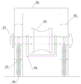
Fig. 1 is a schematic structural diagram of a constant speed winch.
Fig. 2 is a connecting structure of the constant speed winding engine rotating wheel and each belt.
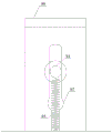
Fig. 3 is a schematic diagram of the belt winding method of the constant speed winding machine.
Fig. 4 is a front view structural view of the belt adjuster.
Fig. 5 is a side view structural view of the belt adjuster.
Fig. 6 adjuster pulley housing.
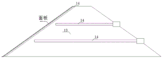
FIG. 7 is a diagram showing a layout of a predetermined measurement track on a surface to be measured.
Fig. 8 is a layout of a monitoring system on a sloped surface of a measured building.
FIG. 9 is a cross-sectional view of the meter operating on a surface being measured.
FIG. 10 is a schematic view of an arrangement of a predetermined measurement track inside a test object.
FIG. 11 is a layout of a monitoring system inside a sloped building under measurement.
FIG. 12 is a layout of the monitoring system inside a low grade building being measured.
Fig. 13 is a structural view of the surveying instrument inside a building to be surveyed.
FIG. 14 is a simplified view of a hand cranking roller structure;
in the figure: the constant-speed winding machine comprises a constant-speed winding machine 1, a constant-speed winding machine support 2, a motor 3, a motor 30, a motor rotating wheel 31, a motor spindle 32, a wire drum 4, a wire drum rotating wheel 40, a wire drum spindle 41, a belt 5, a protective cover 6, a low-power motor 7, a low-power motor rotating wheel 70, a small belt 8, a belt adjuster 9, an adjuster support 90, an adjuster cross shaft 91, an adjusting slide rail 92, an adjuster pulley 93, an adjuster pulley outer frame 94, a spring hook 95, a hook 96, an arc-shaped hole 97, a small belt rope arranger 10, a rope guider 11, a power line 12, a dam 13, a measuring track 14, a measuring instrument 15, a hand-operated winding drum 16 and a three-gear switch 17.
Detailed Description
The invention is further illustrated by the following examples in connection with the accompanying drawings.
A constant speed hoist for engineering measurement is disclosed, as shown in fig. 1 and fig. 2, a hoist bracket 2, a motor 3, a bobbin 4, a belt 5, a protective cover 6, a low-power motor 7, a small belt 8, a belt regulator 9 and a small belt rope arranger 10 are arranged in the constant speed hoist 1; the motor 3, the small belt rope guider 10, the small power motor 7, the belt adjuster 9 and the bobbin 4 are fixed on the winch bracket 2 in sequence; one end of a motor 30 of the motor 3 is provided with a motor rotating wheel 31; the bobbin spindle 41 is arranged in parallel with the motor spindle 32 of the motor 3, the bobbin rotating wheel 40 is arranged at the same end of the bobbin 4 as the motor rotating wheel 31, the motor rotating wheel 31 is connected with the bobbin rotating wheel 40 through a closed-loop belt 5, the low-power motor 7 is arranged between the motor rotating wheel 31 and the bobbin rotating wheel 40 and close to the motor rotating wheel 31, and the low-power motor rotating wheel 70 is connected with the motor rotating wheel 31 through a single-wire small belt 8.
The centers of the rotating wheels of the motor 3, the small-power motor 7 and the bobbin 4 are on the same straight line and are vertical to the motor spindle 32 of the motor 3, and the small-power motor rotating wheel 70 is connected with the motor rotating wheel 31 through a single-wire small belt 8; the small belt 8 is smoothly rotated between the motor wheel 31 and the small power motor wheel 70 by the guidance of the small belt ropewinder 10.
As shown in fig. 1, the belt adjuster 9 is fixed on the winding machine support 2 through an adjuster support 90, and is located between the low-power motor wheel 70 and the bobbin wheel 40 and close to the bobbin wheel 40, and the wheel side of the constant speed winding machine 1 is provided with a protective cover 6.
As shown in fig. 3, one end of the small belt 8 is fixed in the small power motor wheel 70, the other end of the small belt 8 is fixed in the motor wheel 31, and the small belt is wound around the rope guider 11 of the small belt rope guider 10 from the bottom of the motor wheel 31 and then wound around the top of the small power motor wheel 70; the small belt 8 can also be wound to the bottom of the small-power motor rotating wheel 70 through the rope guider 11. The low-power motor rotating wheel 70 can freely rotate in the clockwise or anticlockwise direction when not electrified, and can rotate towards the bobbin rotating wheel 40 side after being electrified and can change the speed at variable frequency;
the motor 3, the small-power motor 7 and the small belt rope arranger 10 share a three-gear switch 17, and the three gears are positive, middle and negative respectively; when the three-gear switch 17 is set to be in a positive gear, the motor 3 rotates clockwise, and the low-power motor rotating wheel 70 is not electrified and can freely rotate along the clockwise or counterclockwise direction; when the third-gear switch 17 is placed in the middle gear, the circuit is in a power-off state; when the three-gear switch 17 is in reverse gear, the motor 3 rotates anticlockwise, the low-power motor 7 is electrified to rotate anticlockwise, and the frequency and the speed can be changed; the tension range of the low-power motor 7 is 0.008-0.015 KN.
As shown in fig. 4, a regulator holder 90, a regulator cross shaft 91, a regulator pulley 93, and a regulator pulley outer frame 94 are provided in the belt regulator 9; hooks 96 are provided at the bottom of both ends of the regulator supporter 90.
As shown in fig. 5, the adjuster mount 90 of the belt adjuster 9 is fixed to the hoist bracket 2, the belt 5 is limited by the adjuster pulley outer frame 94, and the belt 5 passes through the belt adjuster 9 next to the adjuster pulley 93; the regulator cross shaft 91 penetrates through circular holes of the regulator pulley outer frame 94 and the regulator pulley 93, so that the regulator pulley outer frame 94 and the regulator pulley 93 are fixed on the regulator support 90, and the regulator cross shaft 91 has the function of a bolt;
the middle of the two side surfaces of the regulator support 90 is provided with a regulating slideway 92, and the width of the regulating slideway 92 is the same as the outer diameter of the regulator cross shaft 91; the lower part of the adjusting slide way 92 is provided with an arc-shaped hole 97 with the outer diameter larger than that of the horizontal shaft 91 of the adjuster; a spring hook 95 is installed right below the circular arc hole 97, the width of the spring hook 95 is the same as the outer diameter of the spring hook 95, and both ends of the spring hook 95 are connected to the hook 96 and the regulator cross shaft 91, respectively.
As shown in fig. 2 and 4, the spring hook 95 extends and contracts according to the magnitude of the force, and the horizontal shaft 94 of the adjuster slides up and down smoothly in the adjusting slide 92.
As shown in fig. 1, 2 and 3, when the delivery diameter of the motor wheel 31 is D1, the bobbin 4 is wound with the power wire 12, and at this time, the diameter of the bobbin 4 is D'; after the bobbin 4 finishes paying off, the diameter of the bobbin 4 is D, and the diameter of the motor rotating wheel 31 is D1'. Defining parameters: the maximum measurement length of the uniform-speed winch 1 is S, the adjustment length of the small belt 8 is S, the inner width of the wire barrel 4 is L, the inner width of the motor rotating wheel 31 is b, the radius of the power wire 12 is R, and the radius of the small belt 8 is R.
As shown in fig. 3, the inner width of the motor wheel 31 is the same as the inner width of the low power motor wheel 70, and the small belt 8 winds or unwinds one turn in the motor wheel 31 under the adjustment of the small belt rope guider 10, and accordingly the low power motor wheel 70 is unwound or retracted two turns, so that the small belt 8 is neatly arranged in the motor wheel 31 and the low power motor wheel 70.
As shown in figure 2, the small belt 8 is a single line, the cross section of the small belt 8 is circular, the length of the small belt 8 is larger than the adjusting length s, and the small belt 8 is wound on the low-power motor rotating wheel 70 before each measurement. The inner width of the motor rotating wheel 31 is the same as the inner width of the low-power motor rotating wheel 70, under the intelligent adjustment of the small belt rope arranger 10, the small belt 8 winds or is put into the motor rotating wheel 31 for one circle, and correspondingly, the low-power motor rotating wheel 70 is put out or put back for two circles, so that the small belt 8 is arranged in order in the motor rotating wheel 31 and the low-power motor rotating wheel 70.
As shown in fig. 2, when the bobbin 4 is paid off clockwise, the low-power motor 7 does not work, the small belt 8 is wound along the main shaft 32 of the motor under the traction of the motor 3, and is regularly arranged in the motor rotating wheel 31 through the small belt rope arranger 11; when the bobbin 4 is wound up counterclockwise, the small-power motor 7 works synchronously and rotates clockwise, and the small belt 8 is orderly retracted into the small-power motor rotating wheel 70 from the motor rotating wheel 31 by the small-power motor 7 with the aid of the small belt rope guider 10.
As shown in fig. 2 and 5, the bobbin 4 measures the paying-off, the acting force of the belt 5 on the horizontal shaft 91 of the adjuster is increased, and the horizontal shaft 91 of the adjuster moves upwards and slowly towards the adjusting slide way 92; the bobbin 4 measures the take-up, and the acting force of the belt 5 on the regulator cross shaft 91 is reduced, so that the regulator cross shaft 91 slowly moves downwards towards the regulating slide way 92. When the regulator cross shaft 91 is arranged at the top of the regulating slide way 92, the diameter of the motor runner 31 is D1'; when the regulator cross shaft 91 is arranged at the bottom of the regulating slide way 92, the diameter of the motor runner 31 is D1; as shown in fig. 6, in the operation of the belt adjuster 9, the adjuster pulley outer frame 94 rotates the belt 5 against the adjuster pulley 93.
The main technical indexes of the constant speed winch in the embodiment are as follows:
the relationship between the diameter of the bobbin 4 and the diameter of the motor wheel 31 is
The relation between the measuring length S and the adjusting length S of the small belt 8 is
Diameter D of motor runner 311Is a multiple of the diameter D of the small-power motor rotating wheel, and D is taken1=2d。
The measurement length S refers to the allowable measurement range of the constant speed winch 1 or the maximum measurement length S is less than or equal to 450m, and the adjustment length S corresponding to the small belt 8 is less than or equal to 50 m.
The length of the adjustment slide 92 is k (D)1'-D1) And k of each constant speed winch is a fixed constant value.
As shown in fig. 3, preferably, the small belt 8 is wound to the bottom of the small-power motor wheel 70 through the rope guider 11, and the small-power motor wheel 70 is not electrified and freely rotates in the clockwise or counterclockwise direction, but rotates towards the motor wheel 31 side after being electrified and has variable frequency and variable speed.
A method for using a constant-speed winch for engineering measurement comprises the following steps,
A. fixing the head of the linear small belt 8 in the small-power motor rotating wheel 70, then winding the small belt 8 in the small-power motor rotating wheel 70 in order, finally fixing the tail of the small belt 8 in the motor rotating wheel 31, and adjusting the small-power motor rotating wheel 70 to ensure that the small belt 8 is tightly connected with the small-power motor rotating wheel 70 and the motor rotating wheel 31;
B. the elliptic belt 5 is passed through the regulator pulley outer frame 94 and closely attached to the regulator pulley 93, and then the belt regulator 9 is mounted on the winch frame 2; then the motor rotating wheel 31 and the bobbin rotating wheel 40 are connected by a belt 5;
C. after the constant-speed winch 1 is connected, the three-gear switch 17 is placed in reverse gear, the power line 12 is wound into the line barrel 4 in order, then the head of the power line 12 is connected with the measuring instrument 15, and the measuring instrument 15 is placed on the measuring track 14 to prepare for measurement;
D. the three-gear switch 17 is placed in a positive gear, the bobbin 4 is driven by the motor 3 to pay off clockwise, the small belt 8 is drawn by the motor 3 to surround along the main shaft 32 of the motor, so that the inner diameter of the rotating wheel 31 of the motor is increased, and when the measuring instrument 15 reaches a measuring end point, the three-gear switch 17 is placed in a middle gear, and the measurement is stopped;
E. and (3) placing the three-gear switch 17 in a reverse gear, driving the bobbin 4 to take up the wire anticlockwise by the motor 3, returning the measuring instrument 15 to a starting measuring point from an end point, surrounding the small belt 8 along the main shaft of the low-power motor 7 under the traction of the low-power motor 7, reducing the inner diameter, placing the three-gear switch 17 in a middle gear when the measuring instrument 15 reaches the measuring starting point, and stopping measuring.
Taking the measurement of the measuring instrument on the surface of the measured building with the slope as an example, the uniform-speed winch is used for monitoring the interior or appearance of the project, and the specific steps are as follows:
1. when the constant speed winch is used for measuring the appearance of the dam, as shown in fig. 7, 8 and 9, a preset measuring track 14 is installed on the surface of the dam 13, the measuring instrument 15 is placed at the head end of the measuring track 14, the horizontal shaft 91 of the regulator is positioned in the circular arc hole 97 at the bottom end of the regulating slideway, and the regulating length s of the small belt 8 is wound in the small-power motor rotating wheel 70.
A switch of the constant-speed winch 1 is positively turned on, the motor 3 is electrified, the small belt rope arranger 10 is electrified, and the small power motor 7 is not electrified; the bobbin 4 releases the power line 11 clockwise, the measuring instrument 15 starts to move to the bottom of the dam 13 under the traction of the counterweight, the diameter of the bobbin 4 is reduced from D', the small belt 8 surrounds clockwise along the motor rotating wheel 31, and the inner diameter of the motor rotating wheel 31 is enabled to be D1Increasing; at the moment, the small belt 8 surrounds one circle along a certain row of the motor rotating wheel 31, and two circles of small belts 8 are discharged in a certain row corresponding to the small-power motor rotating wheel 70; the inner diameter of the motor runner 31 is increased, so that the acting force of the belt 5 on the regulator cross shaft 91 is increased, and the regulator cross shaft 91 slowly slides upwards on the regulating slide rail 92 due to the force balance effect, so that the belt 5 stably rotates. When the measuring instrument 15 reaches the position of the maximum measuring length S, the diameter of the bobbin 4 is reduced to D after the unwinding is finished, the adjusting length S of the small belt 8 is completely encircled in the motor rotating wheel 31, and the inner diameter of the motor rotating wheel 31 is increased to D1At this time, the regulator horizontal shaft 91 is positioned at the top of the regulating slide 92, and the switch of the constant speed winding machine 1 is turned off.
The switch of the constant speed winch 1 is turned on reversely, the motor 3 is electrified, the small belt rope arranger 10 is electrified, and the small power motor 7 is electrified; the line barrel 4 withdraws the power line 11 anticlockwise, the measuring instrument 15 starts to move towards the top of the dam 13 under the traction of the constant-speed winch, the diameter of the line barrel 4 is increased by D, the small-power motor 7 pulls the small belt 8 to surround the small-power motor rotating wheel 70, and the inner diameter of the motor rotating wheel 31 is enabled to be D1' decrease; the regulator cross shaft 91 slowly moves towards the bottom of the regulating slideway 92; when the measuring instrument 15 returns to the top, the switch of the constant speed winding machine 1 is switched off, and the adjusting length s of the small belt 8 is wound back into the small power motor rotating wheel 70.
2. When the measuring instrument measures the interior appearance of a building with a slope, as shown in fig. 10, a measuring rail 14 is embedded in the bottom of a panel, the measuring mode is carried out according to fig. 11, the measuring rail 14 is an embedded flexible pipeline, and the working principle is consistent with the above except for the difference of the measuring rail 14.
3. When the measuring instrument measures the interior appearance of a low-gradient or horizontal building, as shown in fig. 7 and 10, a measuring track 14 is embedded in the dam body, the measuring mode is carried out according to fig. 12, each constant-speed winch 1 is provided with a power line 12, the power line 12 at the bottom is connected with the head of the measuring instrument 15, and the power line 12 at the upper part is connected with the tail of the measuring instrument 15; alternatively, the upper constant speed winding engine 1 may be replaced with a conventional winding engine or a hand-cranking winding drum 16.
The device comprises a constant-speed winch 1, a measuring instrument 15, a measuring track 14 and an attitude resolving chip; the measuring instrument 15 includes a three-axis fiber optic gyroscope and an attitude measuring instrument, and the attitude measuring instrument can accurately measure attitude angles of inclination, swing and rotation directions under a static condition. And determining the attitude through an attitude measuring instrument, wherein the attitude value is in a functional relation with the deflection of a dam panel or the settlement of a dam body under the condition of constant speed, and the monitoring value of any position along the measuring track can be obtained.
The above-described embodiments are merely preferred embodiments of the present invention, and should not be construed as limiting the present invention, and the scope of the present invention is defined by the claims, and equivalents including technical features described in the claims. I.e., equivalent alterations and modifications within the scope hereof, are also intended to be within the scope of the invention.
Claims (5)
1. The utility model provides a uniform velocity hoist engine that engineering survey used which characterized in that: a winch bracket, a motor, a wire drum, a belt, a protective cover, a low-power motor, a small belt, a belt regulator and a small belt rope arranger are arranged in the constant-speed winch, and the motor, the small belt rope arranger, the low-power motor, the belt regulator and the wire drum are sequentially fixed on the winch bracket; one end of the motor is provided with a motor rotating wheel, a wire drum main shaft is arranged in parallel with the motor main shaft of the motor, the wire drum rotating wheel is arranged at the same end of the wire drum as the motor rotating wheel, the motor rotating wheel is connected with the wire drum rotating wheel through a closed-loop belt, a low-power motor is arranged between the motor rotating wheel and the wire drum rotating wheel and at one side close to the motor rotating wheel, and the low-power motor rotating wheel is connected with the motor rotating wheel through a single-wire small belt;
the centers of the rotating wheels of the motor, the low-power motor and the wire barrel are on the same straight line and are vertical to the motor spindle of the motor, and the rotating wheel of the low-power motor is connected with the rotating wheel of the motor through a single-wire small belt; the small belt is led to rotate stably between the motor rotating wheel and the low-power motor rotating wheel through the guide of the small belt rope guider;
the belt regulator is fixed on the winch bracket through a regulator support, is positioned between the low-power motor rotating wheel and the wire drum rotating wheel and close to one side of the wire drum rotating wheel, and is provided with a protective cover at the rotating wheel side of the constant-speed winch;
one end of the small belt is fixed in the small-power motor rotating wheel, the other end of the small belt is fixed in the motor rotating wheel, and the small belt winds the rope guider of the small belt rope guider from the bottom of the motor rotating wheel and then winds the top of the small-power motor rotating wheel.
2. The constant speed winding machine for engineering measurement according to claim 1, wherein: the belt adjuster is provided with an adjuster support, an adjuster transverse shaft, an adjuster pulley and an adjuster pulley outer frame, and hooks are arranged at the bottoms of the two ends of the adjuster support;
the belt passes through the belt adjuster by clinging to the adjuster pulley under the limit of the adjuster pulley outer frame; the regulator cross shaft penetrates through holes of the regulator pulley outer frame and the regulator pulley, so that the regulator pulley outer frame and the regulator pulley are fixed on the regulator support, and the regulator cross shaft has the function of a bolt;
the middle of two side surfaces of the regulator support is provided with a regulating slideway, and the width of the regulating slideway is the same as the outer diameter of the regulator cross shaft; the lower part of the adjusting slideway is provided with an arc-shaped hole with the outer diameter larger than that of the cross shaft of the adjuster; a spring hook is arranged right below the arc-shaped hole, the width of the adjusting slide way is the same as the outer diameter of the spring hook, and two ends of the spring hook are respectively connected with the hook and the cross shaft of the adjuster;
the spring hook stretches out and draws back according to the stress, and the regulator cross shaft slides up and down stably in the regulating slideway, so that the belt keeps a compact rotating state.
3. The constant speed winding machine for engineering measurement according to claim 1, wherein: when the motor rotating wheel is the delivery diameter D1, the wire barrel is wound with the power wire, and the diameter of the wire barrel is D'; the diameter of the bobbin after the paying-off is finished is D, the diameter of the motor rotating wheel is D1', and the dimensional relationship is that
The relation between the measuring length S and the adjusting length S of the small belt, the inner width L of the wire barrel, the inner width b of the motor rotating wheel, the radius R of the power line and the radius R of the small belt is
The diameter D1 of the motor rotating wheel is a multiple of the diameter D of the low-power motor rotating wheel, and D1 is taken as 2D; the measurement length S refers to the range of measurement allowed by the constant-speed winch, S is required to be less than or equal to 450m, and the adjustment length S corresponding to the small belt is less than or equal to 50 m.
4. The constant speed winding machine for engineering measurement according to claim 1, wherein: the small belt is a single line, the cross section of the small belt is circular, the length of the small belt is greater than the adjusting length s, and the small belt is wound on the rotating wheel of the low-power motor before measurement each time; the inner width of the motor rotating wheel is the same as that of the low-power motor rotating wheel, and the small belt winds or unwinds for one circle in the motor rotating wheel under the adjustment of the small belt rope arranger, and correspondingly the small-power motor rotating wheel is unwound or retracted for two circles, so that the small belt is orderly arranged in the motor rotating wheel and the low-power motor rotating wheel.
5. The use method of the constant-speed winch for engineering measurement is characterized by comprising the following steps of: comprises the following steps of (a) carrying out,
A. fixing the head of a linear small belt in a small-power motor rotating wheel, then regularly winding the small belt in the small-power motor rotating wheel, finally fixing the tail of the small belt in the motor rotating wheel, and adjusting the small-power motor rotating wheel to tightly connect the small belt with the small-power motor rotating wheel and the motor rotating wheel;
B. the elliptic belt passes through the outer frame of the regulator pulley and is tightly attached to the regulator pulley, and then the belt regulator is arranged on the winch bracket; connecting the motor rotating wheel and the wire barrel rotating wheel by using a belt;
C. after the constant-speed winch is connected, the three-gear switch is arranged at a reverse gear, so that the power line is wound into the wire barrel in order, then the head of the power line is connected with the measuring instrument, and the measuring instrument is placed on a measuring track to prepare for measurement;
D. the three-gear switch is placed in a positive gear, the winding drum is driven by the motor to pay off clockwise, the small belt is drawn by the motor to surround along the main shaft of the motor, so that the inner diameter of the rotating wheel of the motor is increased, and when the measuring instrument reaches a measuring end point, the three-gear switch is placed in a middle gear, and the measurement is stopped;
E. and when the measuring instrument reaches the measuring initial point, the three-gear switch is placed in a middle gear, and the measurement is stopped.
Priority Applications (1)
| Application Number | Priority Date | Filing Date | Title |
|---|---|---|---|
| CN201910638625.3A CN110240077B (en) | 2019-07-16 | 2019-07-16 | Constant-speed winch for engineering measurement and using method |
Applications Claiming Priority (1)
| Application Number | Priority Date | Filing Date | Title |
|---|---|---|---|
| CN201910638625.3A CN110240077B (en) | 2019-07-16 | 2019-07-16 | Constant-speed winch for engineering measurement and using method |
Publications (2)
| Publication Number | Publication Date |
|---|---|
| CN110240077A CN110240077A (en) | 2019-09-17 |
| CN110240077B true CN110240077B (en) | 2020-12-25 |
Family
ID=67892315
Family Applications (1)
| Application Number | Title | Priority Date | Filing Date |
|---|---|---|---|
| CN201910638625.3A Expired - Fee Related CN110240077B (en) | 2019-07-16 | 2019-07-16 | Constant-speed winch for engineering measurement and using method |
Country Status (1)
| Country | Link |
|---|---|
| CN (1) | CN110240077B (en) |
Family Cites Families (8)
| Publication number | Priority date | Publication date | Assignee | Title |
|---|---|---|---|---|
| DE3149589A1 (en) * | 1981-12-15 | 1983-06-23 | Stetter Gmbh, 8940 Memmingen | Rope drum for a rope winch of a hoisting machine |
| US7063306B2 (en) * | 2003-10-01 | 2006-06-20 | Paccar Inc | Electronic winch monitoring system |
| JP2012091931A (en) * | 2010-10-28 | 2012-05-17 | Toshinori Iwasaki | Endless winch for collecting thinned-out tree member |
| CN202643202U (en) * | 2012-05-15 | 2013-01-02 | 广州银丽灯具有限公司 | Uniform-speed wire arranging mechanism |
| CN104649166A (en) * | 2014-11-12 | 2015-05-27 | 重庆市大足区力帮机械配件有限公司 | Slow descending device |
| CN204587232U (en) * | 2015-01-14 | 2015-08-26 | 捷胜海洋装备股份有限公司 | A kind of winch tension control structure |
| CN206654674U (en) * | 2017-03-24 | 2017-11-21 | 贾煊 | A kind of winch and cable handler |
| CN108147299A (en) * | 2017-12-29 | 2018-06-12 | 应小平 | A kind of descending lifeline |
-
2019
- 2019-07-16 CN CN201910638625.3A patent/CN110240077B/en not_active Expired - Fee Related
Also Published As
| Publication number | Publication date |
|---|---|
| CN110240077A (en) | 2019-09-17 |
Similar Documents
| Publication | Publication Date | Title |
|---|---|---|
| CN104291150B (en) | Fiber winding method and Filament Winding Equipment | |
| CN110240077B (en) | Constant-speed winch for engineering measurement and using method | |
| CN108548514B (en) | Optical fiber surplus length dynamic measurement system for steel pipe production line | |
| CN205882648U (en) | Cable -placing device | |
| CN101970325B (en) | Method and apparatus for producing cross-wound bobbins | |
| KR100190786B1 (en) | Apparatus for calculating roll diameter of long material winder | |
| CN108415134B (en) | Method for adjusting pay-off tension of casing and master control system | |
| CN103771186A (en) | Winding displacement device | |
| CN110319809B (en) | Line type monitoring device and method for dam interior and appearance | |
| CN210464479U (en) | Underwater construction positioning system | |
| CN107917660A (en) | A kind of measuring apparatus | |
| CN205291303U (en) | Receive multi -wire saw that winding machine arranged perpendicularly | |
| CN102901425A (en) | Lifting height measurement method for bridge crane | |
| CN104003252B (en) | A kind of coil winding system on air yarn cladding machine | |
| US3545725A (en) | Winch having cable position and load indicators | |
| CN110553632A (en) | Underwater construction positioning system | |
| CN109720942A (en) | A kind of controllable type cable winding apparatus | |
| CN114803700A (en) | Control method of vehicle-mounted pay-off and take-up device for light special optical cable | |
| CN210862521U (en) | Synchronous rotary optical fiber length measuring device | |
| CN103331906A (en) | Fiber winding apparatus and winding molding method thereof | |
| CN110424399B (en) | Traffic construction deep basal pit lateral wall skew monitoring devices | |
| CN113800303A (en) | Tension control device of organic film coating equipment and control method thereof | |
| CN105758355B (en) | Hawser traction and measuring motion | |
| CN217155413U (en) | Engineering detection auxiliary device | |
| CN217953331U (en) | Building height detection equipment |
Legal Events
| Date | Code | Title | Description |
|---|---|---|---|
| PB01 | Publication | ||
| PB01 | Publication | ||
| SE01 | Entry into force of request for substantive examination | ||
| SE01 | Entry into force of request for substantive examination | ||
| GR01 | Patent grant | ||
| GR01 | Patent grant | ||
| CF01 | Termination of patent right due to non-payment of annual fee |
Granted publication date: 20201225 Termination date: 20210716 |
|
| CF01 | Termination of patent right due to non-payment of annual fee |