CN110238552B - Device and method for ensuring relative position size of spatial special-shaped pipe - Google Patents
Device and method for ensuring relative position size of spatial special-shaped pipe Download PDFInfo
- Publication number
- CN110238552B CN110238552B CN201910567786.8A CN201910567786A CN110238552B CN 110238552 B CN110238552 B CN 110238552B CN 201910567786 A CN201910567786 A CN 201910567786A CN 110238552 B CN110238552 B CN 110238552B
- Authority
- CN
- China
- Prior art keywords
- positioning
- assembly
- precooler
- mounting
- shaft pin
- Prior art date
- Legal status (The legal status is an assumption and is not a legal conclusion. Google has not performed a legal analysis and makes no representation as to the accuracy of the status listed.)
- Active
Links
Images


Classifications
-
- B—PERFORMING OPERATIONS; TRANSPORTING
- B23—MACHINE TOOLS; METAL-WORKING NOT OTHERWISE PROVIDED FOR
- B23K—SOLDERING OR UNSOLDERING; WELDING; CLADDING OR PLATING BY SOLDERING OR WELDING; CUTTING BY APPLYING HEAT LOCALLY, e.g. FLAME CUTTING; WORKING BY LASER BEAM
- B23K31/00—Processes relevant to this subclass, specially adapted for particular articles or purposes, but not covered by any single one of main groups B23K1/00 - B23K28/00
- B23K31/02—Processes relevant to this subclass, specially adapted for particular articles or purposes, but not covered by any single one of main groups B23K1/00 - B23K28/00 relating to soldering or welding
-
- B—PERFORMING OPERATIONS; TRANSPORTING
- B23—MACHINE TOOLS; METAL-WORKING NOT OTHERWISE PROVIDED FOR
- B23K—SOLDERING OR UNSOLDERING; WELDING; CLADDING OR PLATING BY SOLDERING OR WELDING; CUTTING BY APPLYING HEAT LOCALLY, e.g. FLAME CUTTING; WORKING BY LASER BEAM
- B23K37/00—Auxiliary devices or processes, not specially adapted for a procedure covered by only one of the other main groups of this subclass
- B23K37/04—Auxiliary devices or processes, not specially adapted for a procedure covered by only one of the other main groups of this subclass for holding or positioning work
- B23K37/0426—Fixtures for other work
- B23K37/0435—Clamps
- B23K37/0443—Jigs
Landscapes
- Engineering & Computer Science (AREA)
- Mechanical Engineering (AREA)
- Physics & Mathematics (AREA)
- Optics & Photonics (AREA)
- Butt Welding And Welding Of Specific Article (AREA)
- Automatic Assembly (AREA)
Abstract
The invention discloses a device and a method for ensuring the relative position size of a spatial special pipe by a precooler. During the use, utilize two location dabbers on location support subassembly and the installation support subassembly, the first location pivot and the second location pivot slip regulation welding shrinkage on the cooperation installation support subassembly are welded again after guaranteeing the regulation size, directly inspect on the device after the welding, need not to weld the back again and carry out machine tooling to the precooler.
Description
Technical Field
The invention relates to an integrated assembly, welding and inspection device, in particular to a device for meeting the installation requirement of a precooler and an assembly, welding and inspection method.
Background
The precooler is used for a main refrigeration accessory of the environmental control system and is used for cooling high-temperature bleed air of the aircraft environmental control system by utilizing cold air of an aircraft ram air inlet; the precooler is a typical stainless steel plate fin radiator, and as shown in fig. 1, the structure mainly comprises a flange plate 1, a core subassembly 2, an inlet joint 3, an outlet joint 4, an inlet end cover assembly 5, an outlet end cover assembly 6 and a mounting seat 7. The overall structure of the precooler belongs to a spatial polyhedron, and the overall requirements comprise that:
firstly, the space size of the flange plate, the mounting seat and the inlet and outlet end cover assembly is ensured to meet the technical requirements;
secondly, the product is machined after welding is cancelled, and the excess is prevented from entering the inner cavity of the core.
Therefore, it is considered to ensure the dimensional space between the product flange 1 and the mounting seat 7 and between the inlet and outlet end cover assemblies by using the welding inspection device.
Disclosure of Invention
In view of the problems mentioned in the background art, the present invention aims to provide a device and a method for integrating positioning, assembly welding, bolt connection, positioning and preparing a precooler connecting hole and detecting the precooler connecting hole thereon, which ensure the relative sizes of a precooler flange plate and a mounting seat, namely L1 and L2, and meanwhile, the present invention is mainly characterized in that the space size of the flange plate and an inlet end cover assembly, namely the X axial size: x1, X2, angle A1X, Y axial dimension: y1, angle A1Y; the Z-axis dimension: z1, angle A1Z; the space size of the flange plate and the outlet end cover assembly, namely the X axial size: x3, X4, angle A2X; y-axis dimension: y2, angle A2Y; the Z-axis dimension: z2, angle A2Z. The device and the method need to comprehensively consider various factors such as field processing, welding deformation and the like, and carry out whole-process control on the processing process of welding and inspection.
A device for ensuring the relative position size of a spatial special-shaped pipe comprises,
the mounting bottom plate assembly comprises a mounting bottom plate and a positioning bottom frame, wherein a positioning support assembly mounting hole site, a positioning bottom frame mounting hole site and a mounting support assembly mounting hole site are arranged on the upper end surface of the mounting bottom plate, the positioning bottom frame is detachably connected to the upper end surface of the mounting bottom plate through the positioning bottom frame mounting hole site, and the positioning bottom frame is detachably connected with a flange plate of the precooler;
the positioning support assembly comprises a first positioning support and a second positioning support, the first positioning support and the second positioning support are detachably connected with the upper end face of the mounting bottom plate through positioning support assembly mounting hole positions respectively, and through holes are formed in the first positioning support and the second positioning support;
the mounting bracket assembly is detachably connected with the upper end surface of the mounting base plate through mounting bracket assembly mounting hole positions and comprises two support arms perpendicular to the mounting base plate, and through holes are formed in the support arms;
the positioning mandrel assembly comprises a positioning mandrel and locking screws, the two positioning mandrels are respectively arranged in through holes of the first positioning support and the second positioning support, the tail ends of the two positioning mandrels are detachably connected with a welding joint or a check joint, the appearance of one end of the welding joint is respectively matched with an inlet end cover assembly and an outlet end cover assembly of the precooler, the appearance of one end of the check joint is respectively matched with the inlet end cover assembly and the outlet end cover assembly of the precooler, and the locking screws are arranged along the radial direction of the through holes of the first positioning support and the second positioning support;
the positioning shaft pin assembly comprises a first positioning shaft pin, a locking screw and a second positioning shaft pin, the first positioning shaft pin is arranged in a through hole of the mounting bracket assembly support arm, the locking screw is arranged along the radial direction of the through hole, and the second positioning shaft pin is used for detachably connecting a flange plate of the precooler with the positioning underframe;
and the inspection shaft pins comprise a first inspection shaft pin for replacing the first positioning shaft pin after welding is completed and a second inspection shaft pin for replacing the second positioning shaft pin.
Furthermore, the mounting bottom plate is a rectangular flat plate, an extension plate connected with the mounting support assembly is arranged on one long edge of the mounting bottom plate, and an extension plate connected with the positioning support assembly is arranged on one short edge of the mounting bottom plate.
Furthermore, first location support and second location support comprise long limit and minor face, have an contained angle that is greater than 90 degrees between long limit and the minor face, open on the long limit and have the through-hole and be connected with the positioning core axle subassembly.
Furthermore, the surface of the positioning mandrel is provided with a convex ring with an outer diameter larger than the inner diameter of the through hole on the first positioning support and the second positioning support, the end surface of the positioning mandrel is provided with a screw hole, and the welding joint or the inspection joint is in threaded connection with the positioning mandrel.
A method for ensuring the relative position size of a spatial special pipe by adopting the device comprises the following steps:
step one, mounting one surface with a hole of a flange plate of a precooler core subassembly on a positioning underframe and positioning the surface with a second positioning shaft pin, assembling a precooler mounting seat on a first positioning shaft pin of a mounting bracket assembly, adjusting welding shrinkage by sliding the first positioning shaft pin in a support arm through hole, sliding the first positioning shaft pin in place, performing sheet metal positioning welding on the precooler mounting seat and a side plate on the precooler core subassembly, and finally welding the mounting seat along the periphery after correcting the sheet metal;
assembling the inlet end cover assembly of the precooler on a welding joint of a positioning mandrel assembly, adjusting the welding shrinkage by sliding the positioning mandrel in a through hole, sliding the positioning mandrel in place, then performing sheet metal positioning welding on the inlet end cover assembly of the precooler and an end cover on the core assembly of the precooler, after correcting the sheet metal, ensuring that a product is not interfered with the assembly of the device, and finally welding the mounting seat along the periphery;
assembling the outlet end cover assembly of the precooler on a welding joint of a positioning mandrel assembly, adjusting the welding shrinkage by sliding the positioning mandrel in a through hole, sliding the positioning mandrel in place, then performing sheet metal positioning welding on the outlet end cover assembly of the precooler and an end cover on the core assembly of the precooler, after correcting the sheet metal, ensuring that the assembly of a product and a device is not interfered, and finally welding the mounting seat along the periphery;
and step four, replacing the welding joint with a checking joint, and replacing the first positioning shaft pin and the second positioning shaft pin with a first checking shaft pin and a second checking shaft pin.
Furthermore, before the first step, flanges at two ends of the precooler core assembly are corrected to ensure that the flatness of the flanges meets the requirement.
Further, in the first step, after the first positioning shaft pin slides in place, the relative size of the flange plate of the precooler and the mounting seat is checked, and after the metal plate is corrected, the relative size of the flange plate of the precooler and the mounting seat is ensured.
Further, in the second step, after the positioning mandrel is slid in place, the sizes of the flange plate of the precooler and the cover assembly of the inlet end in the X axis, the Y axis and the Z axis of the space are checked.
Further, in the third step, after the positioning mandrel is slid in place, the sizes of the flange plate of the precooler and the outlet end cover assembly in the X axis, the Y axis and the Z axis of the space are checked.
Compared with the existing processing device and processing inspection method, the invention has the advantages that:
1. the assembly device is relatively simple to manufacture and is convenient to use;
2. the positioning shaft pin assembly is utilized to ensure that the mounting seat is symmetrical about the diagonal line of the side plate when being welded, and meanwhile, the size requirements of L1 and L2 hole sites are met, and the risk that the hole wall is uneven in thickness or broken due to the fact that the hole position deviates from the center of the mounting seat is avoided;
4. the device meets the design size requirement and installation requirement, and has good use effect and stable quality;
5. by using the device, the machining procedure of the product after welding is cancelled, and the risk that the excess material generated by the product after welding enters and exits the inner cavity of the core is avoided;
6. good economic benefit is created while ensuring the quality and quantity of the product to be delivered on time.
Drawings
FIGS. 1-4 are schematic views of precooler components, including critical dimensions to be guaranteed;
FIGS. 2-4, and 3-4 are schematic views of the apparatus after assembly of the precooler from various perspectives;
FIG. 4 is a schematic view of the apparatus with a precooler installed;
FIG. 5 is a three-dimensional schematic view of the apparatus;
FIG. 6 is a mounting bracket detail view;
FIG. 7 is a detail view of a locking screw;
FIG. 8 is a detail view of the first alignment pin;
FIG. 9 is a first inspection shaft pin part view;
FIG. 10 is a detail view of the positioning mandrel;
FIG. 11 is a weld joint detail view;
FIG. 12 is a view of the inspection sub;
FIG. 13 is a detail view of the first positioning bracket;
FIG. 14 is a detail view of a second positioning support;
FIG. 15 is a mounting plate detail view;
FIG. 16 is a view of positioning chassis parts;
FIG. 17 is a second spud pin detail view;
FIG. 18 is a second inspection shaft pin part view.
Detailed Description
The invention is further described with reference to the accompanying drawings, but the scope of protection claimed is not limited thereto.
The technical scheme of the invention is realized as follows:
the device for ensuring the relative position size of the spatial special pipe by the precooler mainly comprises a mounting bottom plate assembly, a positioning support assembly and a mounting support assembly 10.
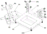
Fig. 2-4, 3-4 and 4 are schematic views of the apparatus with a precooler, wherein:
the mounting bottom plate assembly (see fig. 15 and 16) adopts a split structure, ensures that the mounting bottom plate 81 and the positioning underframe 82 are connected by using 2 cylindrical pins (phi 8x 45) and hexagon socket head cap screws (M8 x 40), ensures the relevant size of a product, and has a safe and reliable structure and convenient operation.
The positioning abutment assembly and the positioning mandrel assembly (shown with reference to fig. 10, 11, 12, 13, 14) comprise: first location support 91, second location support 92, positioning core axle 93, welded joint 94 and check joint, positioning core axle 93 and first location support 91, through-hole sliding fit on the second location support 92, first location support 91, be provided with locking screw (like fig. 7) on the second location support 92, positioning core axle 93 leans on locking screw control at horizontal direction sliding dimension, its main function compensates welding deformation when welding, welded joint 94 changes the check joint after the completion simultaneously, as the inspection frock, high durability and convenient use and reliability.
Mounting bracket assembly 10 (shown in fig. 6, 8 and 9): the mounting bracket is in sliding fit with a first positioning shaft pin 101 (first inspection shaft pin) shaft, a locking screw is arranged on the support arm, the sliding size of the first positioning shaft pin 101 in the horizontal direction is controlled by the locking screw, the main function of the mounting bracket is to compensate welding deformation during welding, and meanwhile, the first positioning shaft pin 101 is replaced by the first inspection shaft pin, so that the mounting bracket is convenient and reliable to use.
Installation of the device (see fig. 5):
1) respectively installing a positioning underframe 82 (shown in figure 16), a positioning support assembly and a mounting bracket assembly 10 on a mounting base plate 81, and connecting by using 8 cylindrical pins (phi 8x 45) and 16 hexagon socket head bolts (M8 x 40) in total;
2) the positioning mandrel assembly is arranged on the positioning support assembly, slides on the positioning support assembly in the horizontal direction, and meanwhile, the locking screw controls the sliding stroke to adjust the welding shrinkage;
3) the positioning shaft pin assemblies are respectively arranged on the mounting bracket assembly 10 and the positioning underframe 82, the first positioning shaft pin slides on the mounting bracket assembly 10 in the horizontal direction, and meanwhile, the locking screw controls the sliding stroke and adjusts the welding shrinkage;
4) the weld joint 94 is used interchangeably with the test joint, the first locating pin and the first test pin, and the second locating pin and the second test pin (fig. 17 and 18);
5) positioning the mandrel assembly: the positioning core shaft 93, the welding joint 94, the inspection joint and the locking screw are connected and fixed;
6) positioning the shaft pin assembly: the first positioning shaft pin 101 is matched with a locking screw, and the second positioning shaft pin 103 is used for positioning and connecting a flange plate and the positioning underframe 82;
7) the mounting base plate assembly 8 adopts a split structure, and the mounting base plate 81 and the positioning underframe 82 are connected by using 2 cylindrical pins (phi 8x 45) and hexagon socket head cap screws (M8 x 40).
The method for performing assembly welding inspection on the precooler by adopting the device comprises the following steps:
1. correcting the flange plates 1 at two ends of the precooler core assembly 2 to ensure that the flatness of the flange plates 1 is not more than 0.3 mm;
2. installing one surface with a hole of a flange plate 1 of a precooler core assembly 2 on a positioning underframe 82 of the device, positioning the surface by using a second positioning shaft pin 103, assembling a precooler mounting seat 7 on a first positioning shaft pin 101 of a mounting bracket assembly 10, adjusting the welding shrinkage by sliding the first positioning shaft pin 101 in a support arm through hole, sliding the first positioning shaft pin 101 in place, and checking the size: l1 and L2, performing sheet metal positioning welding on the precooler mounting seat 7 and the side plate on the core subassembly 2, after sheet metal correction, ensuring the sizes of L1 and L2, and finally welding the mounting seat 7 along the periphery;
3. assembling the precooler inlet end cover assembly 5 on a welding joint 94 of the positioning support assembly, sliding a positioning mandrel 93 in the positioning mandrel assembly in a through hole of the first positioning support 91 to adjust the welding shrinkage, sliding the positioning mandrel 93 in place, and checking the size: x1, X2, Y1, A1X, A1Y and A1z, then performing sheet metal positioning welding on the inlet end cover assembly 5 and the end cover on the core assembly 2, and after sheet metal correction, ensuring that the product is not interfered with the assembly of the device;
4. assembling the precooler outlet end cover assembly 6 on a welding joint 94 of a positioning support assembly, sliding a positioning mandrel 93 in the positioning mandrel assembly in a through hole of a second positioning support 92 to adjust the welding shrinkage, sliding the positioning mandrel 93 in place, and checking the size: x3, X4, Z2, A1X, A1y and A1Z, then performing sheet metal positioning welding on the outlet end cover assembly 6 and the end cover on the core assembly 2, and after sheet metal correction, ensuring that the product is not interfered with the assembly of the device;
5. the welding joint 94 on the device is replaced by a detection joint, the first positioning shaft pin 101 is replaced by a first detection shaft pin, and the second positioning shaft pin 103 is replaced by a second detection shaft pin, so that the precooler is ensured to have no interference with the welding detection clamp;
in the welding process, the positioning shaft pin assembly and the positioning mandrel assembly solve the problem that parts cannot be installed on the device after welding deformation, and the positioning shaft pin assembly and the positioning mandrel assembly can also align the angle of the relative position of the inclined edge and the side edge of the precooler after the installation base 7 and the inlet end cover and the outlet end cover deform, so that the design requirement is ensured. The structure does not need to disassemble the positioning core shaft 93, the first positioning shaft pin 101 and the second positioning shaft pin 103, and the device can directly slide, fix, debug and align, and is convenient and reliable to use. And finally, unloading the qualified product which is subjected to assembly inspection from the clamp, and cleaning and inspecting.
The basic principles and the main features of the present invention are shown and described above, the present invention is not limited by the above embodiments, the above embodiments and descriptions are only for the basic principles of the present invention, and any variations, modifications, equivalents, and the like based on the technical solutions of the present invention should fall within the protection scope of the present invention.
Claims (9)
1. An apparatus for ensuring the relative position and size of spatial special pipes is characterized in that: comprises the steps of (a) preparing a mixture of a plurality of raw materials,
the mounting bottom plate assembly comprises a mounting bottom plate and a positioning bottom frame, wherein a positioning support assembly mounting hole site, a positioning bottom frame mounting hole site and a mounting support assembly mounting hole site are arranged on the upper end surface of the mounting bottom plate, the positioning bottom frame is detachably connected to the upper end surface of the mounting bottom plate through the positioning bottom frame mounting hole site, and the positioning bottom frame is detachably connected with a flange plate of the precooler;
the positioning support assembly comprises a first positioning support and a second positioning support, the first positioning support and the second positioning support are detachably connected with the upper end face of the mounting bottom plate through positioning support assembly mounting hole positions respectively, and through holes are formed in the first positioning support and the second positioning support;
the mounting bracket assembly is detachably connected with the upper end surface of the mounting base plate through mounting bracket assembly mounting hole positions and comprises two support arms perpendicular to the mounting base plate, and through holes are formed in the support arms;
the positioning mandrel assembly comprises a positioning mandrel and locking screws, the two positioning mandrels are respectively arranged in through holes of the first positioning support and the second positioning support, the tail ends of the two positioning mandrels are detachably connected with a welding joint or a check joint, the appearance of one end of the welding joint is respectively matched with an inlet end cover assembly and an outlet end cover assembly of the precooler, the appearance of one end of the check joint is respectively matched with the inlet end cover assembly and the outlet end cover assembly of the precooler, and the locking screws are arranged along the radial direction of the through holes of the first positioning support and the second positioning support;
the positioning shaft pin assembly comprises a first positioning shaft pin, a locking screw and a second positioning shaft pin, the first positioning shaft pin is arranged in a through hole of the mounting bracket assembly support arm, the locking screw is arranged along the radial direction of the through hole, and the second positioning shaft pin is used for detachably connecting a flange plate of the precooler with the positioning underframe;
and the inspection shaft pins comprise a first inspection shaft pin for replacing the first positioning shaft pin after welding is completed and a second inspection shaft pin for replacing the second positioning shaft pin.
2. An apparatus for ensuring the relative dimensional position of spatial profile tubes according to claim 1, wherein: the mounting bottom plate is a rectangular flat plate, an extension plate connected with the mounting support assembly is arranged on one long edge of the mounting bottom plate, and an extension plate connected with the positioning support assembly is arranged on one short edge of the mounting bottom plate.
3. An apparatus for ensuring the relative dimensional position of spatial profile tubes according to claim 1, wherein: the first positioning support and the second positioning support are composed of long edges and short edges, an included angle larger than 90 degrees is formed between the long edges and the short edges, and through holes are formed in the long edges and connected with the positioning mandrel component.
4. An apparatus for ensuring the relative dimensional position of spatial profile tubes according to claim 1, wherein: the surface of the positioning mandrel is provided with a convex ring with an outer diameter larger than the inner diameter of the through hole on the first positioning support and the second positioning support, the end surface of the positioning mandrel is provided with a screw hole, and a welding joint or a check joint is in threaded connection with the positioning mandrel.
5. A method for ensuring the relative dimensions of spatial profile tubes using the apparatus of claim 1, comprising the steps of:
step one, mounting one surface with a hole of a flange plate of a precooler core subassembly on a positioning underframe and positioning the surface with a second positioning shaft pin, assembling a precooler mounting seat on a first positioning shaft pin of a mounting bracket assembly, adjusting welding shrinkage by sliding the first positioning shaft pin in a support arm through hole, sliding the first positioning shaft pin in place, performing sheet metal positioning welding on the precooler mounting seat and a side plate on the precooler core subassembly, and finally welding the mounting seat along the periphery after correcting the sheet metal;
assembling the inlet end cover assembly of the precooler on a welding joint of a positioning mandrel assembly, adjusting the welding shrinkage by sliding the positioning mandrel in a through hole, sliding the positioning mandrel in place, then performing sheet metal positioning welding on the inlet end cover assembly of the precooler and an end cover on the core assembly of the precooler, after correcting the sheet metal, ensuring that a product is not interfered with the assembly of the device, and finally welding the mounting seat along the periphery;
assembling the outlet end cover assembly of the precooler on a welding joint of a positioning mandrel assembly, adjusting the welding shrinkage by sliding the positioning mandrel in a through hole, sliding the positioning mandrel in place, then performing sheet metal positioning welding on the outlet end cover assembly of the precooler and an end cover on the core assembly of the precooler, after correcting the sheet metal, ensuring that the assembly of a product and a device is not interfered, and finally welding the mounting seat along the periphery;
and step four, replacing the welding joint with a checking joint, and replacing the first positioning shaft pin and the second positioning shaft pin with a first checking shaft pin and a second checking shaft pin.
6. A method of ensuring the relative positional dimensions of a spatial profile tube according to claim 5, wherein: before the first step, the flanges at two ends of the precooler core assembly are corrected to ensure that the flatness of the flanges meets the requirement.
7. A method of ensuring the relative positional dimensions of a spatial profile tube according to claim 5, wherein: in the first step, after the first positioning shaft pin slides in place, the relative size of the flange plate of the precooler and the mounting seat is checked, and after the metal plate is corrected, the relative size of the flange plate of the precooler and the mounting seat is ensured.
8. A method of ensuring the relative positional dimensions of a spatial profile tube according to claim 5, wherein: in the second step, after the positioning core shaft is slid in place, the sizes of the flange plate of the precooler and the cover assembly of the inlet end in the X axis, the Y axis and the Z axis of the space are checked.
9. A method of ensuring the relative positional dimensions of a spatial profile tube according to claim 5, wherein: and in the third step, after the positioning mandrel is slid in place, the sizes of the flange plate of the precooler and the outlet end cover assembly in the X axis, the Y axis and the Z axis are checked.
Priority Applications (1)
| Application Number | Priority Date | Filing Date | Title |
|---|---|---|---|
| CN201910567786.8A CN110238552B (en) | 2019-06-27 | 2019-06-27 | Device and method for ensuring relative position size of spatial special-shaped pipe |
Applications Claiming Priority (1)
| Application Number | Priority Date | Filing Date | Title |
|---|---|---|---|
| CN201910567786.8A CN110238552B (en) | 2019-06-27 | 2019-06-27 | Device and method for ensuring relative position size of spatial special-shaped pipe |
Publications (2)
| Publication Number | Publication Date |
|---|---|
| CN110238552A CN110238552A (en) | 2019-09-17 |
| CN110238552B true CN110238552B (en) | 2021-02-26 |
Family
ID=67889894
Family Applications (1)
| Application Number | Title | Priority Date | Filing Date |
|---|---|---|---|
| CN201910567786.8A Active CN110238552B (en) | 2019-06-27 | 2019-06-27 | Device and method for ensuring relative position size of spatial special-shaped pipe |
Country Status (1)
| Country | Link |
|---|---|
| CN (1) | CN110238552B (en) |
Families Citing this family (2)
| Publication number | Priority date | Publication date | Assignee | Title |
|---|---|---|---|---|
| CN115781164B (en) * | 2022-12-19 | 2025-12-02 | 中国航发贵州黎阳航空动力有限公司 | A fixture for welding, straightening, and inspecting fuel lines for aircraft engines. |
| CN120038533B (en) * | 2025-03-11 | 2026-04-21 | 贵州永红航空机械有限责任公司 | Processing method of cantilever structure radiator |
Family Cites Families (5)
| Publication number | Priority date | Publication date | Assignee | Title |
|---|---|---|---|---|
| CN202541838U (en) * | 2012-01-17 | 2012-11-21 | 中国商用飞机有限责任公司 | Precooler positioning device |
| US10619569B2 (en) * | 2016-06-17 | 2020-04-14 | United Technologies Corporation | Gas turbine engine and method to cool a gas turbine engine case assembly |
| CN208408996U (en) * | 2018-05-23 | 2019-01-22 | 贵州永红航空机械有限责任公司 | A kind of positioning welding tooling for ring flange ozzle and heat sink assembly |
| CN208372780U (en) * | 2018-05-29 | 2019-01-15 | 浙江磊纳微粉材料有限公司 | A kind of frozen compressed air dryer |
| CN109540439B (en) * | 2018-12-20 | 2020-11-20 | 贵州永红航空机械有限责任公司 | Vibration clamp for vibration control of precooler and test method |
-
2019
- 2019-06-27 CN CN201910567786.8A patent/CN110238552B/en active Active
Also Published As
| Publication number | Publication date |
|---|---|
| CN110238552A (en) | 2019-09-17 |
Similar Documents
| Publication | Publication Date | Title |
|---|---|---|
| CN110238552B (en) | Device and method for ensuring relative position size of spatial special-shaped pipe | |
| CN203197774U (en) | Automobile part hole position detecting positioning integrated tool | |
| CN116984803A (en) | Welding deformation control tool and method for fuel oil main pipe | |
| CN117283354B (en) | A fixture for rapid multi-angle pose adjustment of an antenna radome and its usage method | |
| CN115673691B (en) | A propellant storage tank flange shape and installation hole accuracy installation assurance method | |
| CN120269287B (en) | Welding jig that flange processing was used | |
| CN110142704B (en) | Welding inspection method for aluminum plate-fin radiator | |
| CN108655772B (en) | Turning Fixtures for Gas Turbine Fairings | |
| CN223029116U (en) | Clamping tool for inner sleeve of casing | |
| CN217965412U (en) | Aviation radiator external surface positioning and cutting device | |
| CN214350608U (en) | Welding and inspection tool for liquid helium storage tank | |
| CN219788328U (en) | Loose location marking tool | |
| CN109341466A (en) | A kind of measuring device and method of hydraulic actuator bulk | |
| CN213496746U (en) | Adjustable universal milling device with inner cavity for positioning | |
| CN110977332B (en) | Manufacturing tooling of crane top structural parts and manufacturing method thereof | |
| CN115805444A (en) | A Helicopter Tail Rotor Control Fork Processing Device | |
| CN223492589U (en) | Positioning angular welding tool for multiple non-looper flanges | |
| CN222492860U (en) | High-precision adjustable rear wall skeleton assembly positioning device | |
| CN223776419U (en) | Tool for welding branch pipes on cylindrical products | |
| CN207730125U (en) | Pressure container cylinder internal diameter and ovality detecting tool | |
| CN118989849A (en) | Flexible device for assembling and welding oil guide connecting pipe and use method | |
| CN223863223U (en) | Pipeline butt welding tool | |
| CN114178557B (en) | Cylindrical skin processing method | |
| CN215698048U (en) | Centering device for center height of tool nose of lathe | |
| CN218904172U (en) | Welding positioning fixture mechanism of robot with adjustable degree of freedom |
Legal Events
| Date | Code | Title | Description |
|---|---|---|---|
| PB01 | Publication | ||
| PB01 | Publication | ||
| SE01 | Entry into force of request for substantive examination | ||
| SE01 | Entry into force of request for substantive examination | ||
| GR01 | Patent grant | ||
| GR01 | Patent grant |