CN110234933B - Liquid circulation system and method for operating the same - Google Patents
Liquid circulation system and method for operating the same Download PDFInfo
- Publication number
- CN110234933B CN110234933B CN201780070812.5A CN201780070812A CN110234933B CN 110234933 B CN110234933 B CN 110234933B CN 201780070812 A CN201780070812 A CN 201780070812A CN 110234933 B CN110234933 B CN 110234933B
- Authority
- CN
- China
- Prior art keywords
- valve
- control
- liquid circulation
- flow
- circulation system
- Prior art date
- Legal status (The legal status is an assumption and is not a legal conclusion. Google has not performed a legal analysis and makes no representation as to the accuracy of the status listed.)
- Active
Links
- 239000007788 liquid Substances 0.000 title claims abstract description 107
- 238000000034 method Methods 0.000 title claims description 55
- 230000006872 improvement Effects 0.000 claims abstract description 10
- 239000012530 fluid Substances 0.000 claims description 38
- 230000010355 oscillation Effects 0.000 claims description 33
- 230000001629 suppression Effects 0.000 claims description 10
- 230000003068 static effect Effects 0.000 claims description 8
- 238000012544 monitoring process Methods 0.000 claims description 4
- 230000003213 activating effect Effects 0.000 claims description 2
- 230000015556 catabolic process Effects 0.000 claims description 2
- 238000006731 degradation reaction Methods 0.000 claims description 2
- 230000008569 process Effects 0.000 description 15
- 239000004793 Polystyrene Substances 0.000 description 11
- 238000010438 heat treatment Methods 0.000 description 11
- 230000001276 controlling effect Effects 0.000 description 8
- 230000001105 regulatory effect Effects 0.000 description 5
- XLYOFNOQVPJJNP-UHFFFAOYSA-N water Substances O XLYOFNOQVPJJNP-UHFFFAOYSA-N 0.000 description 5
- 230000003044 adaptive effect Effects 0.000 description 4
- 238000001914 filtration Methods 0.000 description 4
- 238000004378 air conditioning Methods 0.000 description 3
- 239000013256 coordination polymer Substances 0.000 description 3
- 238000001514 detection method Methods 0.000 description 3
- 230000000694 effects Effects 0.000 description 3
- 238000009423 ventilation Methods 0.000 description 3
- 230000009471 action Effects 0.000 description 2
- 230000002411 adverse Effects 0.000 description 2
- 238000004364 calculation method Methods 0.000 description 2
- 239000000498 cooling water Substances 0.000 description 2
- 238000013016 damping Methods 0.000 description 2
- 230000001066 destructive effect Effects 0.000 description 2
- 238000010586 diagram Methods 0.000 description 2
- 230000037361 pathway Effects 0.000 description 2
- 239000000779 smoke Substances 0.000 description 2
- 238000013528 artificial neural network Methods 0.000 description 1
- 238000005452 bending Methods 0.000 description 1
- 230000008901 benefit Effects 0.000 description 1
- 230000008859 change Effects 0.000 description 1
- 238000004891 communication Methods 0.000 description 1
- 238000013461 design Methods 0.000 description 1
- 230000006870 function Effects 0.000 description 1
- 230000005484 gravity Effects 0.000 description 1
- 238000005259 measurement Methods 0.000 description 1
- 230000007246 mechanism Effects 0.000 description 1
- 239000002184 metal Substances 0.000 description 1
- 229910052751 metal Inorganic materials 0.000 description 1
- 230000004048 modification Effects 0.000 description 1
- 238000012986 modification Methods 0.000 description 1
- 229920002223 polystyrene Polymers 0.000 description 1
- 230000000306 recurrent effect Effects 0.000 description 1
- 230000004044 response Effects 0.000 description 1
- 238000010187 selection method Methods 0.000 description 1
- 230000036962 time dependent Effects 0.000 description 1
- 238000012546 transfer Methods 0.000 description 1
Images


Classifications
-
- F—MECHANICAL ENGINEERING; LIGHTING; HEATING; WEAPONS; BLASTING
- F24—HEATING; RANGES; VENTILATING
- F24F—AIR-CONDITIONING; AIR-HUMIDIFICATION; VENTILATION; USE OF AIR CURRENTS FOR SCREENING
- F24F11/00—Control or safety arrangements
- F24F11/70—Control systems characterised by their outputs; Constructional details thereof
- F24F11/80—Control systems characterised by their outputs; Constructional details thereof for controlling the temperature of the supplied air
- F24F11/83—Control systems characterised by their outputs; Constructional details thereof for controlling the temperature of the supplied air by controlling the supply of heat-exchange fluids to heat-exchangers
- F24F11/84—Control systems characterised by their outputs; Constructional details thereof for controlling the temperature of the supplied air by controlling the supply of heat-exchange fluids to heat-exchangers using valves
-
- F—MECHANICAL ENGINEERING; LIGHTING; HEATING; WEAPONS; BLASTING
- F24—HEATING; RANGES; VENTILATING
- F24D—DOMESTIC- OR SPACE-HEATING SYSTEMS, e.g. CENTRAL HEATING SYSTEMS; DOMESTIC HOT-WATER SUPPLY SYSTEMS; ELEMENTS OR COMPONENTS THEREFOR
- F24D2220/00—Components of central heating installations excluding heat sources
- F24D2220/04—Sensors
- F24D2220/044—Flow sensors
Abstract
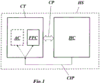
A liquid circulation system (HS) comprises at least one liquid circulation circuit (HC) and a control device (CT) for controlling the operation of the at least one liquid circulation circuit (HC) via a Control Path (CP), whereby the control device (CT) comprises a Feed Forward Controller (FFC). The operation of the system is improved by said liquid circulation system (HS) further comprising a Control Improvement Path (CIP) extending from said at least one liquid circulation circuit (HC) to said control device (CT), by means of which Control Improvement Path (CIP) said control device (CT) can be improved in case said liquid circulation system (HS) becomes unstable and/or shows poor system control.
Description
Technical Field
The present invention relates to a liquid circulation system. It relates to a liquid circulation system according to the preamble of claim 1.
It also relates to a method for operating such a liquid circulation system.
Background
Liquid circulation systems are part of the HVAC field. In most cases, such liquid circulation systems include one or more control valves for controlling the flow of fluid (liquid or gas) through conduits connecting various parts of the liquid circulation system.
Associated with these control valves is the well-known concept of so-called "valve authority".
As shown in fig. 2, a liquid circulation system 20 in a general form includes a pump 11, a two-port control valve 12, and a terminal unit (in this case, a heat exchanger 13) in a closed circuit. The pump 11, the control valve 12 and the terminal unit 13 are connected in series. When the pump 11 pumps fluid through the circuit at a certain pressure, in each section of the systemThere is a pressure drop Δ p. These pressure drops or differential pressures may be divided into a first pressure differential Δ p at the control valve 12valveAnd a second pressure difference Δ p at the rest of the circuitcircuit(see FIG. 2).
Now, when commissioning such a liquid circulation system 20, the control valve 12 must be selected according to the needs of the system:
when the control valve 12 is undersized, the pressure drop across the system increases, which means that the pump 11 will use a greater amount of energy to pump enough fluid through the system. On the other hand, the accuracy of the control increases, because the desired control can be achieved with the entire control range of the valve.
When the control valve is oversized, the energy required to pump the necessary flow through the system will be reduced. However, this energy savings will come at the expense of reduced control accuracy at the control valve 12, as the initial travel of the valve from the fully open toward the more closed position will have no effect on fluid flow. Thus, only a relatively small portion of the entire control range of the valve 12 is useful for control, resulting in insufficient control, with poor stability and accuracy.
Therefore, there is a trade-off between the two scenarios described above; and the proper dimensioning of the control valve 12 requires a compromise between control accuracy and reduced energy losses. This is where the valve authority concept works.
The valve authority N of a control valve such as the control valve 12 is defined as:

wherein Δ pvalveIs the pressure drop, Δ p, over the fully open control valvecircuitIs the pressure drop in the rest of the circuit, kvsvalveIs the flow coefficient (in metric units) of a fully open control valve, and kvcircuitAre the corresponding flow coefficients of the rest of the circuit outside the control valve.
In other words, the valve weight N within the hydronic system indicates how much of the total pressure drop of the system comes from the control valve. In practice, a range of valve weights N between 0.2 and 0.5 is considered acceptable. According to equation (1) above, if the valve weight N is too high (above 0.5 or 50%), the control valve may be undersized and thus the liquid circulation system will benefit from a larger sized valve in order to reduce losses caused by excessive pressure drop. If the value is too low (below 0.2 or 20%), the valve movement has only a marginal impact with respect to the overall system, and therefore the valve may be oversized, resulting in poor control.
In general, the flow coefficient kv of the part x of the hydronic system (as used in equation (1)) is defined by the following relationship,

for water as the fluid, has a specific gravity G = 1, where Φ is the fluid flow through the portion and Δ PxIs the pressure drop over the portion x.
Therefore, the temperature of the molten metal is controlled,

and

the valve authority N has been used in the past in control schemes in HVAC environments.
Document US5579993a relates to a controller implemented in a heating, ventilation and air conditioning (HVAC) distribution system that provides improved control by implementing a General Recurrent Neural Network (GRNN) to generate control signals based on identifying characteristics of components used within the HVAC system.
The local controller disclosed in US5579993A comprises feedforward means for generating a feedforward control signal based on an identification characteristic of a local component (e.g. a damper or a valve) and a calculated system variable, and feedback means for generating a feedback control signal based on a measured system variable. The controller then controls the component based on a combination of the feedforward control signal and the feedback signal.
The local controller includes two independent processes: an identification process and a control process. The identification process identifies certain characteristics of the local component. These identified characteristics are output to a control process. The control process accepts the identified features and other signals and outputs control signals to provide global control of the HVAC system.
In particular, the identification process utilizes a look-up table to store the characteristics of the local component. These features are the ratio of the pressure drop across the local component to the drop in branch pressure (valve weight in the case of a valve) when the component is fully open, the percentage of flow through the component being normalized to the maximum flow through the component.
The control process is divided into a feed-forward process and a feedback process. The feedback process accepts as inputs the calculated flow set point and the feedforward control signal. The feedback process uses these signals to generate the control signal.
The feed forward process begins by first receiving a fan static pressure set point. The fan static pressure set point is used to calculate the pressure loss in each of the i branches connecting the fan outlet and the individual local dampers. In particular, the pressure loss of each of the i branches is adaptively determined in real time. To calculate the pressure loss of branch 1, certain calculation steps are followed. The next step is to calculate the pressure loss of the second stage. This pressure loss is added to the pressure loss of the first section to produce the pressure loss of branch 1. This method of calculating the pressure loss is applied to the i additional branches connected to the main pipe.
Document US 6095426 relates generally to control systems and more particularly to control systems for heating, ventilation and air conditioning fluid distribution systems.
US 6095426 discloses a controller for controlling the temperature within a room in a building having at least one space adjacent the room, the building having a heating, ventilation and air conditioning (HVAC) system, having a supply duct adapted to supply air to the room, and a common exhaust duct adapted to exhaust air from the room. The system has a local component for controlling a supply air flow into a room having at least one additional exhaust independent of the HVAC system. The controller includes a feedforward arrangement for generating a feedforward control signal based on a desired temperature and flow set point in the supply conduit, the flow into and out of the room, the flow set point in the general exhaust conduit, and based on the identified characteristics of the component and the calculated system variables. The controller also includes feedback means for generating a feedback control signal based on the measured system variable, and means for combining the feedforward and feedback control signals to effect control of the local component.
US 6095426 also discloses a method of determining a value of a control signal in a controller for controlling an outlet air temperature to a room from an air supply duct, which is part of an HVAC system of a building, the air duct having: a heating coil adapted to heat air moving through the duct; and a flow valve for controlling the flow of the hot water through the heating coil. The controller is of the type having identification means for periodically generating identification features of the heating coil and the valve, and means for measuring the temperature of the air at the outlet of the duct, means for measuring the flow rate of air through the duct, and means for measuring the water pressure in the system passing through the valve and in which the valve is connected. The control signal is based on the control set point and the identifying characteristics of the heating coil and the valve. The method comprises the following steps: activating the identification device to determine the effectiveness of the coil to transfer heat to the air flowing through the conduit; using the coil characteristics to produce a desired water flow rate through the heating coil for a given measured duct outlet air temperature and air flow rate; measuring the total pressure drop across the valve into the system when the valve is fully open and determining the ratio of the former to the latter to derive a weight value for the valve; and generating the control signal as a function of the water flow rate and the valve weight.
Document EP1235131B1 discloses a process for controlling the room temperature, comprising: a first temperature sensor for measuring room temperature; a second temperature sensor for measuring a feed-forward temperature of the heating medium; a third temperature sensor for metering the return temperature of the heating medium; and a control unit for actuating the valve for the flow of the heating medium. In this process, the operating characteristics of the valve are determined from the measured values of the room temperature sensor, the feed-forward temperature and the return temperature, wherein the control parameters of the room temperature control are adjusted for the operating characteristics in response to the operating point of the valve.
Document CN105335621A relates to an electric control valve model selection method. The method for selecting the electric control valve model comprises the following steps: determining the use performance of the electric regulating valve, selecting the type of a flow characteristic curve of the valve according to the use performance, and mainly selecting the diameter of a valve seat; according to the main selected diameter of the valve seat, inquiring a design manual to obtain a valve adjustable ratio R, a flow capacity kv of the valve and a valve weight S, determining a maximum aperture value K = 90% and a minimum aperture value K = 30% of the valve seat diameter; substituting parameters including R, kv, S, K = 90% and K = 30% into an actual flow characteristic formula of the electric adjustment valve, respectively, to obtain a flow rate at a 30% aperture and a flow rate at a 90% aperture; determining the flow range Q of a connecting pipe of a cooling water systemmin-QmaxWhether or not from the range of Q30%To Q90%(ii) a If Q ismin-QmaxIn the range of from Q30%To Q90%Then completing model selection; and if Qmin-QmaxIs not in the range of Q30%To Q90%Then return to the step of primarily selecting the seat diameter and continue model selection until the seat diameter satisfies the condition. According to the method provided, model selection parameters of the valve are matched to the operating conditions of the cooling water system, so that the valve can exhibit relatively good turndown performance.
In general, poor valve authority results in poor system control and instability.
Another problem is the so-called "hunting": control of the hydronic circuit may be prone to undesirable oscillations, which also results in poor and unstable system control.
Document WO2006/105677a2 discloses a method and a device for damping vibrations in an apparatus, comprising an actuator for actuating a flap or a valve for metering the volume flow of gas or liquid, in particular in the field of HVAC, fire protection or smoke protection. The vibrations of the flap or valve caused by an adverse or erroneous adjustment or configuration and/or destructive effects of the controller are detected and mitigated or suppressed by means of an algorithm stored in the microprocessor. The algorithm is preferably based on the identification of the vibrating component, adaptive filtering and the identification of sudden load changes.
Disclosure of Invention
The object of the present invention is to provide a liquid circulation system which avoids certain disadvantages of the known liquid circulation systems and which in a simple manner is able to adapt to changes in the hydraulic parameters of the system.
It is another object of the invention to teach a method for operating such a system.
These and other objects are achieved by claims 1, 10, 11, 16 and 19.
The liquid circulation system according to the invention comprises at least one liquid circulation loop and a control device for controlling the operation of the at least one liquid circulation loop via a control path, whereby the control device comprises a feed forward controller.
Characterised in that the hydronic system further comprises a control improvement path extending from the at least one hydronic circuit to the control means, by which the control means can be improved when the hydronic system becomes unstable and/or the system control is indicated to be poor.
According to one embodiment of the invention said at least one liquid circulation loop comprises control valves as variable flow resistance and static flow resistance, which are connected in series by a conduit, whereby said control valves are controlled by valve control means, wherein a flow sensor is provided for measuring the flow of fluid through said loop, and wherein valve weight determination means are associated with said liquid circulation loop, whereby said valve weight determination means are connected to said valve control means for receiving information about the actual open position of said control valves, and whereby said valve weight determination means are also connected to said flow sensor for receiving information about the actual fluid flow through said loop.
A memory may be associated with the valve authority determination device that contains and provides information to the valve authority determination device regarding the valve characteristics of the control valve.
Also, an outlet of the valve authority determination device may be connected to the feed forward controller.
According to an embodiment of the invention, a frequency detector for detecting oscillations is provided in the liquid circulation system and is in operative connection with the control device.
The control means may comprise oscillation suppression means and the frequency detector may be operatively connected to the oscillation suppression means.
Furthermore, the feedforward controller may comprise a physical model of the liquid circulation loop, and the oscillation suppression means may have an influence on an input and/or output signal of the physical model.
In particular, the oscillation suppression means may comprise at least one filter.
According to another embodiment of the invention, the control means may comprise an alternative controller and the frequency detector may be operatively connected to switching means for switching between the feedforward controller and the alternative controller.
A method for operating a liquid circulation system according to the invention, which liquid circulation system comprises control valves as variable flow resistance and static flow resistance, which are connected in series by a pipeline, whereby said control valves are controlled by valve control means, wherein a flow sensor is provided for measuring the flow of fluid through said circuit, and wherein valve weight determination means are associated with said liquid circulation circuit, whereby said valve weight determination means are connected to said valve control means for receiving information about the actual open position of said control valves, and whereby said valve weight determination means are further connected to said flow sensor for receiving information about the actual fluid flow through said circuit, the method comprising the steps of:
a. providing a valve characteristic of the control valve comprising a dependence of a flow coefficient (kv) of the valve on an open position of the valve;
b. moving the control valve to have a first flow coefficient (kv)valve,1) A first open position;
c. measuring the flow rate (Φ) of the circulating fluid through the control valve in the first open position1);
d. Moving the control valve to have a second flow coefficient (kv)valve,2) A second open position;
e. measuring the flow rate (Φ) of the circulating fluid through the control valve in the second open position2);
f. According to the measured flow rate (phi)1,Φ2) And corresponding flow coefficient (kv)valve,1, kvvalve,2) Determining the valve authority (N) using the following formula

Wherein

And kvsvalveIs the flow coefficient of a fully open valve.
Another method for operating a liquid circulation system according to the invention, the liquid circulation system comprising control valves as variable flow resistance and static flow resistance, which are connected in series by a pipeline, whereby said control valves are controlled by a valve control means, wherein a flow sensor is provided for measuring the flow of fluid through said circuit, and wherein a valve weight determination means is associated with said liquid circulation circuit, whereby said valve weight determination means is connected to said valve control means for receiving information about the actual open position of said control valves, and whereby said valve weight determination means is further connected to said flow sensor for receiving information about the actual fluid flow through said circuit, the method comprising the steps of:
a. providing a valve characteristic shape of the control valve comprising a primary dependence of a flow coefficient (kv) of the valve on an open position of the valve;
b. moving the control valve to a first open position;
c. measuring the flow rate (Φ) of the circulating fluid through the control valve in the first open position1);
d. Moving the control valve to a second open position different from the first position;
e. measuring the flow rate (Φ) of the circulating fluid through the control valve in the second open position2);
f. Moving the control valve to a third open position different from the first and second open positions;
g. measuring the flow rate (Φ) of the circulating fluid through the control valve in the third open position3);
h. Measuring flow from three (phi)1, Φ2, Φ3) Determining the flow coefficient (kv) of the circuitcircuit) And the flow coefficient (kvs) of the fully open control valve (12)valve) (ii) a And
i. determining a valve authority (N) of the control valve (12) using the following equation

The valve authority may be determined at a predetermined time during the life of the liquid circulation system.
In particular, the valve authority may be determined during commissioning of the liquid circulation system.
Additionally, the valve authority may be determined at least a second time during a lifetime of the liquid circulation system.
Further, the valve control device may comprise a feed forward part and the determined valve authority may be used as a parameter in the feed forward part of the valve control device.
A further method of operating a liquid circulation system according to the invention, wherein a frequency detector for detecting oscillations is provided in the liquid circulation system and the frequency detector is operatively connected to the control device, comprises the steps of:
a. monitoring a flow and/or setpoint signal through the liquid circulation system by means of the frequency detector;
b. acting on the control means when the frequency detector detects oscillation.
In particular, oscillation suppression means may be activated in the control means when oscillation is detected by the frequency detector.
Alternatively, the feed forward controller may be replaced by an alternative controller when the frequency detector detects oscillation.
Another method of operating a liquid circulation system according to the invention, wherein a frequency detector for detecting oscillations is provided in the liquid circulation system and is operatively connected with the control device, and wherein the control device comprises an alternative controller and the frequency detector is operatively connected with a switching device for switching between the feed-forward controller and the alternative controller, the method comprising the steps of:
a. monitoring a flow and/or setpoint signal through the liquid circulation system by means of the frequency detector;
b. replacing the alternative controller by the feed forward controller when oscillation is detected by the frequency detector.
Drawings
The invention will now be explained in more detail by means of different embodiments and with reference to the accompanying drawings.
FIG. 1 illustrates, in a general configuration, a fluid circulation system including a fluid circulation circuit and a control device interacting through a control pathway and a control improvement pathway, in accordance with an embodiment of the present invention;
FIG. 2 shows a basic liquid circulation loop including a pump, control valves and a heat exchanger;
FIG. 3 shows a "learning" hydronic system according to an embodiment of the present invention based on the circuit of FIG. 2, and further including a control device capable of reacting to changes in certain parameters of the hydronic circuit through valve authority learning;
FIG. 4 shows a diagram relating to a first method of weight learning used in the present invention;
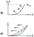
FIG. 5 shows a diagram relating to a second method of weight learning used in the present invention;
FIG. 6 illustrates a "learn" fluid circulation system according to another embodiment of the present invention;
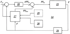
FIG. 7 illustrates a feed-forward control scheme that may be used to implement a valve authority learning method according to the present application;
FIG. 8 illustrates an improved feed forward control scheme that may be used to suppress unwanted oscillations of the system; and
fig. 9 shows another way of handling unwanted oscillations of the system by switching between different controllers.
Illustration of the drawings
10,20 liquid circulation loop
11 Pump
12 control valve
13 heat exchanger
14 valve control device (or actuator)
15 memory
16-valve weight determining device
17 valve authority using unit
18 flow sensor
19,19' pipe
21,22 loop element
23 feedforward section (valve control device)
24 feed forward control scheme
24a, b feedforward control scheme
25 controlled system flow
26 flow sensor
27 physical model
28 degree of authority of valve
29 other input parameters (e.g. valve characteristics)
30 deviation part
31 frequency detector
32,33 filter
34 disabling device (e.g. switch)
35 filter device
AC alternative controller
CIP control improvement path
CP control path
CT control device
EV energy valve
Flow rate of F
FsvFlow set point
FFC feedforward controller
HC liquid circulation loop
HS liquid circulation system
ΔPSsvDeviation of valve position set point
PSsvValve position set point
PSFSVFeedforward valve position setpoint
kvvalveFlow coefficient of control valve
Flow of phi through the control valve
ΔpvalvePressure drop at control valve
ΔpcircuitPressure drop of external circuit of control valve
Detailed Description
Fig. 1 shows a liquid circulation system HS according to an embodiment of the invention in a general configuration. The liquid circulation system HS comprises a liquid circulation circuit HC, which is usually associated with the building and comprises pipes, valves, heat exchangers, pumps, etc., and a control device CT, which interact via a control path CP and a control improvement path CIP. The control path CP is related to the communication between the control device CT and the liquid circulation circuit and is a path for exchanging control signals from the control device CT to the liquid circulation circuit HC and operating parameters from the liquid circulation circuit HC to the control device CT. The control device CT comprises a feedforward controller FFC, which contains a physical model of the liquid circulation loop HC. The control device CT may also comprise an alternative controller AC, which may replace the feedforward controller FFC, and vice versa. The switching between the two controllers FFC and AC is represented in fig. 1 by a selector switch.
Depending on the conditions in the liquid circulation circuit, the improvement of the control can be achieved in different ways:
during commissioning of the system it may be necessary and/or advantageous to adapt the control device CT to certain parameters of the system, which are not known prior to commissioning.
Longer system operation may result in changes and/or degradation of important system parameters, which may result in poor and unstable system control.
There are in particular two cases, which are related to the controllability of the liquid circulation system:
1) as long as the control valve is part of the liquid circulation loop, the so-called "valve authority" is an important parameter: poor valve authority can lead to poor and unstable system control
2) Sometimes the liquid circulation system is susceptible to undesirable oscillations, so-called "hunting": the wobble signal also causes poor and unstable system control.
According to the invention, by a corresponding modification of the control device, the negative effects of the time-dependent changes in the valve authority or an insufficient knowledge of the actual valve authority will be avoided.
As already described in the introductory part, fig. 2 shows a liquid circulation system 20 in its most general form, which comprises, in a closed circuit, a pump 11, a two-port control valve 12 and a terminal unit, in this case a heat exchanger 13. The pump 11, the control valve 12 and the terminal unit 13 are connected in series. When the pump 11 pumps fluid through the circuit at a certain pressure, there is a pressure drop Δ p in various parts of the system. These pressure drops or differential pressures may be divided into a first pressure differential Δ p at the control valve 12valveAnd a second pressure difference Δ p of the rest of the circuitcircuit。
In this circuit, the valve authority N is the pressure drop across the fully open valve relative to the pressure drop across the entire system. The valve weight N is defined by equations (1) to (4) above, indicating how well the liquid circulation system is controllable (the higher the valve weight N, the better the liquid circulation system can be controlled). However, the valve weight N is not a parameter, and is constant throughout the life of the system. When the valve authority N changes due to a change in the system, it would be advantageous to have the valve authority learning capability of the system in order to adapt the control mechanism of the system to the changing system environment.
The present invention relates to such valve authority learning.
At least two different valve authority learning procedures are possible within the scope of the invention. They all comprise active measurement of the valves in the hydraulic circuit, which means that the valves are actively moved between different valve positions.
When all valve characteristics are known, a first of these at least two different procedures is selected. In this case, the curve kv shown in fig. 4(a) is known for the valve position. Furthermore, as a main assumption, there should be a constant pressure over the relevant area of the system.
To evaluate the actual valve authority of the control valve 12, the valve is moved to two different positions. These positions are characterized in fig. 4 by two corresponding kv values, i.e. kvvalve,1(for position 1) and kvvalve,2(for position 2). In each of these two positions, the associated flow rate Φ (FIG. 4(b)) is measured and stored with its associated kv value, giving pairs of values Φ1, kvvalve,1And phi2, kvvalve, 2。
Based on these value pairs, the actual valve weight N may be calculated by the following equation:


when only the shape of the valve feature is known but no scaling is available, the second of these at least two different procedures is selected. In this case, the curve kv versus valve position (shown in FIG. 5 (a)) is the value kvs andparameter nglFunction F (kvs, n)gl) Which is a measure of the apparent degree of curve bending of the characteristic curve. For example, when the curve represents a valve having an "equal percentage characteristic", nglAnd = 3. With other nglThe curve of values is shown in fig. 5(a) by the dashed and dotted lines.
Also, as a primary assumption, there should be a constant pressure over the relevant area of the system.
The valve now moves to three (different) positions (fig. 5 (b)). Measuring the respective flow rates phi at these locations1, Φ2And phi3And stored.
Finally, the stored flow can be used to solve for a solution with 3 unknowns kvcircuit, kvsvalveAnd Δ p.
In order to move the control valve 12 to different positions and to measure the respective flow circulating through the conduit 19 and the valve, a valve control device 14 and a flow sensor 18 are provided in the liquid circulation system 10 according to fig. 3. Both devices are connected to a valve authority determination device 16 which controls the measuring actions of the control valve 12 and the flow sensor 18. As mentioned above, the memory 15 may be used to store certain parameters of the valve characteristics that are necessary for the valve weighting calculation. As shown, the valve authority measured and calculated from time to time by the valve authority determination device 16 may be transmitted to the valve authority use unit 17. The valve weighting unit 17 may then control the valve control means 14 accordingly.
The valve weighting N may be determined at predetermined times during the life of the fluid circulation system 10. Furthermore, the valve authority N may be determined during commissioning of the fluid circulation system 10, and preferably at least a second time during the lifetime of the fluid circulation system.
Since the valve control means 14 comprises (except for possible feedback) a feed forward component 23, as shown in fig. 6, said determined valve weighting N can be used as a parameter in the feed forward part 23 of the valve control means 14.
As shown in fig. 6, the liquid circulation circuit 10 may be a simple circuit having a pump 11, a control valve 12, and a heat exchanger 13. However, there may be further circuit elements 21 and branches comprising further ducts 19' and circuit elements 22.
Finally, the arrangement of the control valve 12, the valve control means (or actuator) 14, the flow sensor 18 and the valve authority determination means 16 and the memory 15 may be combined in one unit, which is referred to as an "energy valve" EV (see e.g. EP2896899a 1).
Fig. 7 shows a feed forward control scheme that can be used to implement the valve authority learning strategy explained so far. The central part of the forward control scheme 24 of fig. 7 is the physical model 27 of the liquid circulation system in question. When a flow set point F is givensvThe physical model 27 is then modeled by using the flow set point FsvThe measured actual flow F, the valve weighting 28, and other input parameters 29 (e.g., valve characteristics) produce a feed forward position set point PSFsv. Deviation of valve position set point Δ PSsvAdded to the feedforward position set value PSFsvDerived from a flow set point FsvAnd the difference between the measured actual flow rate F is determined in a deviation portion 30. Rather than because the physical model 27 does not match reality, the deviation portion 30 occurs for small deviations. PS (polystyrene) with high sensitivityFsvAnd Δ PSsvThe sum of (c) is ultimately used as the valve position set point PSsvFor controlling the controlled system flow 25. The resulting actual flow rate F is measured by the flow sensor 26.
The valve authority 28 placed into the physical model 27 is the valve authority determined by the method described above. In this way, the feed forward control can react to changes in the relevant system parameters to improve system control and stability.
However, as described above, other features of the system besides valve authority may trigger actions on the feed-forward control scheme. For example, document WO2006/105677a2 discloses a method and a device for damping vibrations in an apparatus, which comprises an actuator for actuating a flap or a valve for metering the gas or liquid volume flow, in particular in the field of HVAC, fire protection or smoke protection. The vibrations of the flap or valve caused by an adverse or erroneous adjustment or configuration and/or destructive effects of the controller are detected and mitigated or suppressed by means of an algorithm stored in the microprocessor. The algorithm is preferably based on the identification of the vibrating component, adaptive filtering and the identification of sudden load changes.
In particular, according to this document, a regulating variable from the regulating path is provided, whereby the regulating variable corresponds to the effective liquid volume flow. Furthermore, a predetermined control signal corresponding to the desired liquid volume flow is provided. The predetermined control signal is compared to the regulated variable and the regulator output variable is calculated therefrom. The regulator output variable is monitored by a vibration detection algorithm. If the vibration detection algorithm does not detect a vibration of the regulator output variable, the regulator output variable is fed to an actuating device which actuates a damper or valve in the conduit for metering the gas or liquid volumetric flow. On the other hand, if the vibration detection algorithm detects a vibration in the regulator output variable, the regulator output variable is fed to the adaptive filter, and the adaptive filter suppresses the vibration and generates a control signal with suppressed or damped vibration of the regulator output variable, which is then used to actuate the device instead of the regulator output variable.
In this example of a feed forward control scheme, the situation is different: as shown in fig. 8, a modified feed forward control scheme 24a may be used to suppress unwanted oscillations of the system. To detect unwanted oscillations of the system, a frequency detector 31 may be connected to the flow sensor 26. When the frequency detector 31 detects an undesired oscillation in the system, the appropriate input or output signal of the physical model 27 will be compensated or filtered (e.g., with a lead or lag filter or a combination thereof). As an example, fig. 8 shows two filters 32 and 33 (dashed lines) at the input of the flow set point Fsv and at the output of the flow signal F of the flow sensor 26. Additional filtering means 35 may be used to filter the valve position set Point (PS)sv). Other locations for filtering and/or compensation are also possible.
In addition, the setpoint signal flow setpoint FsvAnd/or position set value PSsvMay be monitored by the frequency detector 31.
Another method of handling unwanted oscillations of the system is shown in fig. 9: when the frequency detector 31 of the feedforward control scheme 24b detects unwanted oscillations, it actuates a disabling device 34 (e.g. a switch) to turn off the actual feedforward control and replace it with an alternative, more suitable and oscillation-free controller AC. In other cases, the switching may be reversed such that the system switches from the alternative controller AC to the feed forward controller to improve stability and control.
Claims (20)
1. A liquid circulation system comprising at least one liquid circulation loop (10; 20) and control means for controlling the operation of the at least one liquid circulation loop (10; 20) by means of a control path, whereby the control means comprises a feed forward controller (23), characterized in that the liquid circulation system further comprises a control improvement path extending from the at least one liquid circulation loop (10; 20) to the control means, by which the control means can be improved in case the liquid circulation system becomes unstable and shows poor system control, wherein the instability of the liquid circulation system and the poor system control are caused by parameter variations and/or degradation during operation of the liquid circulation system; the at least one liquid circulation circuit (10) comprises control valves (12) as variable flow resistance and static flow resistance (13) which are connected in series by conduits (19,19'), whereby the control valves (12) are controlled by a valve control means (14), wherein a flow sensor (18) is provided for measuring the flow (Φ) of the fluid flowing through the circuit, and wherein a valve authority determination means (16) is associated with the liquid circulation circuit (10), whereby the valve authority determination means (16) is connected to the valve control means (14) for receiving information about the actual open position of the control valves (12), and whereby the valve authority determination means (16) is further connected to the flow sensor (18) for receiving information about the actual fluid flow (Φ) flowing through the circuit.
2. The fluid circulation system of claim 1, wherein: poor valve authority leads to instability and poor system control.
3. The fluid circulation system of claim 1, wherein: the wobble signal causes instability and poor system control.
4. The hydronic system according to claim 1, characterized in that a memory (15) is associated with the valve authority determination device (16), the memory (15) containing and providing information to the valve authority determination device (16) about valve characteristics of the control valve (12).
5. A liquid circulation system according to claim 1, characterized in that the outlet of the valve authority determining means (16) is connected to the feed forward controller.
6. A liquid circulation system according to claim 1, wherein a frequency detector (31) for detecting oscillations is provided in the liquid circulation system, and the frequency detector (31) is operatively connected with the control means.
7. A liquid circulation system according to claim 6, wherein the control means comprises oscillation suppression means (32,33,35) and the frequency detector (31) is operatively connected to the oscillation suppression means (32,33, 35).
8. The hydronic system according to claim 7, wherein the feedforward controller comprises a physical model (27) of the hydronic circuit, and the oscillation suppression means (32,33,35) have an influence on input and/or output signals of the physical model (27).
9. A liquid circulation system according to claim 7 or claim 8, wherein the oscillation suppression means comprises at least one filter (32, 33).
10. The liquid circulation system according to claim 6, wherein the control means comprises an alternative controller and the frequency detector (31) is operatively connected with switching means for switching between the feed forward controller and the alternative controller.
11. Method for operating a liquid circulation system comprising at least one liquid circulation loop (10; 20) and a control device for controlling the operation of the at least one liquid circulation loop (10; 20) by means of a control path, whereby the control device comprises a feed forward controller (23), the liquid circulation system further comprising a control improvement path extending from the at least one liquid circulation loop (10; 20) to the control device, by means of which the control device can be improved in case the liquid circulation system becomes unstable and shows poor system control, the at least one liquid circulation loop (10) comprising a control valve (12) as variable flow resistance and static flow resistance (13), which are connected in series by means of a conduit (19,19'), whereby the control valve (12) is controlled by a valve control means (14), wherein a flow sensor (18) is provided for measuring the flow (Φ) of the fluid flowing through the circuit, and wherein a valve authority determination means (16) is associated with the liquid circulation circuit (10), whereby the valve authority determination means (16) is connected to the valve control means (14) for receiving information about the actual open position of the control valve (12), and whereby the valve authority determination means (16) is also connected to the flow sensor (18) for receiving information about the actual fluid flow (Φ) flowing through the circuit, characterized in that the method comprises the steps of:
a. providing a valve characteristic of the control valve (12) comprising a dependence of a flow coefficient (kv) of the control valve on an open position of the control valve;
b. moving the control valve (12) to have a first flow coefficient (kv)valve,1) A first open position;
c. measuring the flow rate (Φ) of the circulating fluid through the control valve (12) in the first open position1);
d. Moving the control valve (12) to have a second flow coefficient (kv)valve,2) A second open position;
e. measuring through the door in the second open positionThe flow rate (phi) of the circulating fluid of the control valve (12)2);
f. Using the following formula, from the measured flow (Φ)1, Φ2) And said first and second flow coefficients (kv) respectivelyvalve,1, kvValve,2) Determining a valve weighting (N),


And kvsvalveThe flow coefficient of the control valve being fully open.
12. Method for operating a liquid circulation system comprising at least one liquid circulation loop (10; 20) and a control device for controlling the operation of the at least one liquid circulation loop (10; 20) by means of a control path, whereby the control device comprises a feed forward controller (23), the liquid circulation system further comprising a control improvement path extending from the at least one liquid circulation loop (10; 20) to the control device, by means of which the control device can be improved in case the liquid circulation system becomes unstable and shows poor system control, the at least one liquid circulation loop (10) comprising a control valve (12) as variable flow resistance and static flow resistance (13), which are connected in series by means of a conduit (19,19'), whereby the control valve (12) is controlled by a valve control means (14), wherein a flow sensor (18) is provided for measuring the flow (Φ) of the fluid flowing through the circuit, and wherein a valve authority determination means (16) is associated with the liquid circulation circuit (10), whereby the valve authority determination means (16) is connected to the valve control means (14) for receiving information about the actual open position of the control valve (12), and whereby the valve authority determination means (16) is also connected to the flow sensor (18) for receiving information about the actual fluid flow (Φ) flowing through the circuit, characterized in that the method comprises the steps of:
a. providing a valve characteristic shape of the control valve (12) comprising a main dependence of a flow coefficient (kv) of the control valve on an open position of the control valve;
b. moving the control valve (12) to a first open position;
c. measuring the flow rate (Φ) of the circulating fluid through the control valve (12) in the first open position1);
d. Moving the control valve (12) to a second open position different from the first open position;
e. measuring the flow rate (Φ) of the circulating fluid through the control valve (12) in the second open position2);
f. Moving the control valve (12) to a third open position different from the first and second open positions;
g. measuring the flow rate (Φ) of the circulating fluid through the control valve (12) in the third open position3);
h. The flow rate (phi) measured from three1, Φ2, Φ3) Determining a flow coefficient (kv) of the loopcircuit) And a flow coefficient (kvs) of the control valve (12) fully openedvalve) (ii) a And
i. determining a valve authority (N) of the control valve (12) using the following equation

13. A method according to claim 11 or claim 12, wherein the valve weighting (N) is determined at predetermined times during the lifetime of the liquid circulation system.
14. Method according to claim 13, characterized in that the valve weighting (N) is determined during commissioning of the liquid circulation system.
15. Method according to claim 14, characterized in that the valve authority (N) is determined at least a second time during the lifetime of the liquid circulation system.
16. The method according to claim 15, characterized in that the valve control means (14) comprises a feed forward controller (23) and that the determined valve authority (N) is used as a parameter in the feed forward controller (23) of the valve control means (14).
17. A method according to claim 11 or 12, wherein a frequency detector (31) for detecting oscillations is provided in the liquid circulation system, and the frequency detector (31) is operatively connected with the control means, the method comprising the steps of:
a1. monitoring a flow and/or a set point signal (F) through the liquid circulation system by means of the frequency detector (31)sv, PSsv);
b1. Acting on the control means when the frequency detector detects oscillation.
18. A method according to claim 17, characterized by activating oscillation suppression means (32,33,35) in the control means when oscillation is detected by the frequency detector (31).
19. The method according to claim 17, characterized in that the feed forward controller is replaced by an alternative controller when the frequency detector (31) detects oscillations.
20. Method according to claim 11 or 12, characterized in that a frequency detector (31) for detecting oscillations is provided in the liquid circulation system and that the frequency detector (31) is in operative connection with the control device, the control device comprising an alternative controller and that the frequency detector (31) is in operative connection with a switching device for switching between the feed forward controller and the alternative controller, the method comprising the steps of:
a1. monitoring a flow and/or a set point signal (F) through the liquid circulation system by means of the frequency detector (31)sv, PSsv);
b1. When the frequency detector (31) detects oscillation, the alternative controller is replaced by the feedforward controller.
Applications Claiming Priority (3)
| Application Number | Priority Date | Filing Date | Title |
|---|---|---|---|
| CH01540/16 | 2016-11-22 | ||
| CH15402016 | 2016-11-22 | ||
| PCT/EP2017/073640 WO2018095609A2 (en) | 2016-11-22 | 2017-09-19 | Hydronic system and method for operating such hydronic system |
Publications (2)
| Publication Number | Publication Date |
|---|---|
| CN110234933A CN110234933A (en) | 2019-09-13 |
| CN110234933B true CN110234933B (en) | 2021-10-26 |
Family
ID=57421586
Family Applications (1)
| Application Number | Title | Priority Date | Filing Date |
|---|---|---|---|
| CN201780070812.5A Active CN110234933B (en) | 2016-11-22 | 2017-09-19 | Liquid circulation system and method for operating the same |
Country Status (4)
| Country | Link |
|---|---|
| US (1) | US10890351B2 (en) |
| EP (1) | EP3545239A2 (en) |
| CN (1) | CN110234933B (en) |
| WO (1) | WO2018095609A2 (en) |
Families Citing this family (3)
| Publication number | Priority date | Publication date | Assignee | Title |
|---|---|---|---|---|
| US10876776B1 (en) * | 2017-12-15 | 2020-12-29 | Robert Senia | System and method for freeze protection of an air handling system |
| CN114222891B (en) * | 2019-07-22 | 2023-12-05 | 贝利莫控股公司 | Method and system for balancing a torus network |
| US11898761B2 (en) * | 2020-03-04 | 2024-02-13 | Harvest Thermal, Inc. | Control systems and methods for managing rate of heat delivery in hydronic systems |
Family Cites Families (24)
| Publication number | Priority date | Publication date | Assignee | Title |
|---|---|---|---|---|
| US3170630A (en) * | 1963-08-21 | 1965-02-23 | American Radiator & Standard | Control circuit for hydronic system |
| CH644460A5 (en) * | 1980-02-27 | 1984-07-31 | Aquametro Ag | SYSTEM FOR TRANSPORTING HEAT BY MEANS OF A FLUID. |
| AU560995B2 (en) * | 1984-02-07 | 1987-04-30 | Toshiba, Kabushiki Kaisha | Process control apparatus |
| US5579993A (en) | 1995-01-06 | 1996-12-03 | Landis & Gyr Powers, Inc. | HVAC distribution system identification |
| US6095426A (en) | 1997-11-07 | 2000-08-01 | Siemens Building Technologies | Room temperature control apparatus having feedforward and feedback control and method |
| DE19911237C2 (en) * | 1999-03-15 | 2001-02-08 | Danfoss As | Heating system and method for its operation |
| DE10026957A1 (en) * | 2000-05-30 | 2001-12-13 | Techem Service Ag | Method and device for detecting changes in environmental variables |
| DE10108852C1 (en) | 2001-02-23 | 2002-08-29 | Techem Service Ag | Room temperature control |
| US7592033B2 (en) * | 2003-07-08 | 2009-09-22 | Computrol, Inc | Variable fluid dispenser |
| JP2006039663A (en) * | 2004-07-22 | 2006-02-09 | Hitachi Ltd | Liquid-circulating system and liquid-cooling system using the same |
| US7865338B2 (en) | 2005-04-07 | 2011-01-04 | Belimo Holding Ag | Suppression of vibrations |
| DE102005045198C5 (en) * | 2005-09-21 | 2009-06-25 | Techem Energy Services Gmbh | Method and device for determining thermal characteristics of a radiator |
| US7966104B2 (en) * | 2007-03-26 | 2011-06-21 | Siemens Corporation | Apparatus and method for the control of the indoor thermal environment having feed forward and feedback control using adaptive reference models |
| CN101709899B (en) * | 2009-12-10 | 2012-08-08 | 吴永雄 | Intelligent thermostatic control device for pipeline supply hot water system |
| DE102009060262A1 (en) * | 2009-12-23 | 2011-06-30 | Samson Aktiengesellschaft, 60314 | Method and arrangement for controlling a process fluid flow and positioner |
| CH705143A1 (en) | 2011-06-30 | 2012-12-31 | Belimo Holding Ag | Method and apparatus for balancing a group of consumers in a fluid transport system. |
| AT513733A1 (en) * | 2012-10-30 | 2014-06-15 | Vaillant Group Austria Gmbh | Method for hydraulic adjustment of a heating system |
| CH707402A2 (en) | 2012-12-18 | 2014-06-30 | Belimo Holding Ag | Method and device for balancing a group of consumers in a fluid transport system. |
| US9921011B2 (en) | 2013-12-20 | 2018-03-20 | Belimo Holding Ag | Valve control in an HVAC system with sensors |
| US9864383B2 (en) * | 2015-04-02 | 2018-01-09 | Belimo Holding Ag | Method and system for determining characteristic parameters of a hydraulic network |
| CN204717081U (en) * | 2015-06-08 | 2015-10-21 | 宁波埃美柯铜阀门有限公司 | Adjustable flow type dynamic balance valve |
| CN105335621B (en) | 2015-11-13 | 2021-07-20 | 中国核电工程有限公司 | Model selection method for electric straight-through regulating valve |
| US11371734B2 (en) * | 2016-06-03 | 2022-06-28 | Belimo Holding Ag | Method and computer system for monitoring an HVAC system with data from a plurality of HVAC controllers |
| EP3475623B1 (en) * | 2016-06-22 | 2021-06-30 | Belimo Holding AG | Method and devices for controlling a fluid transportation network |
-
2017
- 2017-09-19 CN CN201780070812.5A patent/CN110234933B/en active Active
- 2017-09-19 EP EP17765473.8A patent/EP3545239A2/en active Pending
- 2017-09-19 US US16/333,354 patent/US10890351B2/en active Active
- 2017-09-19 WO PCT/EP2017/073640 patent/WO2018095609A2/en unknown
Also Published As
| Publication number | Publication date |
|---|---|
| CN110234933A (en) | 2019-09-13 |
| WO2018095609A3 (en) | 2018-07-05 |
| WO2018095609A2 (en) | 2018-05-31 |
| US20190264947A1 (en) | 2019-08-29 |
| US10890351B2 (en) | 2021-01-12 |
| EP3545239A2 (en) | 2019-10-02 |
Similar Documents
| Publication | Publication Date | Title |
|---|---|---|
| US6095426A (en) | Room temperature control apparatus having feedforward and feedback control and method | |
| RU2660721C2 (en) | Device and method for controlling opening of valve in hvac system | |
| US11175039B2 (en) | Regulating turbulent flows | |
| CN110234933B (en) | Liquid circulation system and method for operating the same | |
| US7775865B2 (en) | Set and forget exhaust controller | |
| AU743848B2 (en) | Room pressure control apparatus having feedforward and feedback control and method | |
| US10852041B2 (en) | HVAC system with electronically controlled expansion valve | |
| Taylor | Increasing efficiency with VAV system static pressure setpoint reset | |
| JP6004228B2 (en) | Air conditioner | |
| JP2004227574A (en) | System and method for transferring heat | |
| JP2007532851A5 (en) | ||
| US10914480B2 (en) | Building control system with decoupler for independent control of interacting feedback loops | |
| Salsbury | A temperature controller for VAV air-handling units based on simplified physical models | |
| CN113439186B (en) | Apparatus and method for controlling an orifice of a valve in an HVAC system | |
| Xu et al. | A robust sequencing control strategy for air-handling units | |
| Rasmussen et al. | Heating, Ventilating, and Air-Conditioning Control Systems | |
| EP3407153B1 (en) | Control of pressure controller at border values | |
| WO2023110361A1 (en) | Heating system with automatic differential pressure setting | |
| JP2019158172A (en) | Humidifier control method and humidification system | |
| Osman et al. | Feedforward-feedback controller using general regression neural network (GRNN) for laboratory HVAC system: Part III--temperature control--heating | |
| Nardone | Control System Fundamentals |
Legal Events
| Date | Code | Title | Description |
|---|---|---|---|
| PB01 | Publication | ||
| PB01 | Publication | ||
| SE01 | Entry into force of request for substantive examination | ||
| SE01 | Entry into force of request for substantive examination | ||
| GR01 | Patent grant | ||
| GR01 | Patent grant |