CN1102302C - Coil connecting structure in outer rotor-type multi-pole generator - Google Patents
Coil connecting structure in outer rotor-type multi-pole generator Download PDFInfo
- Publication number
- CN1102302C CN1102302C CN98120831A CN98120831A CN1102302C CN 1102302 C CN1102302 C CN 1102302C CN 98120831 A CN98120831 A CN 98120831A CN 98120831 A CN98120831 A CN 98120831A CN 1102302 C CN1102302 C CN 1102302C
- Authority
- CN
- China
- Prior art keywords
- coil
- terminal component
- clamping plate
- base portion
- stator core
- Prior art date
- Legal status (The legal status is an assumption and is not a legal conclusion. Google has not performed a legal analysis and makes no representation as to the accuracy of the status listed.)
- Expired - Fee Related
Links
- 230000005405 multipole Effects 0.000 title claims abstract description 12
- 238000012856 packing Methods 0.000 claims description 6
- 239000002184 metal Substances 0.000 claims description 4
- 238000005452 bending Methods 0.000 description 6
- 238000010586 diagram Methods 0.000 description 6
- 238000007634 remodeling Methods 0.000 description 4
- 238000005476 soldering Methods 0.000 description 3
- 238000001816 cooling Methods 0.000 description 1
- 230000000694 effects Effects 0.000 description 1
- 238000000034 method Methods 0.000 description 1
- 230000007935 neutral effect Effects 0.000 description 1
- 238000005192 partition Methods 0.000 description 1
- 238000007789 sealing Methods 0.000 description 1
- 239000000758 substrate Substances 0.000 description 1
- 238000004804 winding Methods 0.000 description 1
Images


Classifications
-
- H—ELECTRICITY
- H02—GENERATION; CONVERSION OR DISTRIBUTION OF ELECTRIC POWER
- H02K—DYNAMO-ELECTRIC MACHINES
- H02K3/00—Details of windings
- H02K3/46—Fastening of windings on the stator or rotor structure
- H02K3/52—Fastening salient pole windings or connections thereto
- H02K3/521—Fastening salient pole windings or connections thereto applicable to stators only
- H02K3/522—Fastening salient pole windings or connections thereto applicable to stators only for generally annular cores with salient poles
-
- H—ELECTRICITY
- H02—GENERATION; CONVERSION OR DISTRIBUTION OF ELECTRIC POWER
- H02K—DYNAMO-ELECTRIC MACHINES
- H02K11/00—Structural association of dynamo-electric machines with electric components or with devices for shielding, monitoring or protection
- H02K11/40—Structural association with grounding devices
Abstract
An outer rotor-type multi-pole generator includes a plurality of coils wound around a large number of protruding poles provided around an outer periphery of a stator core through a bobbin, and terminal members fitted into fitting tube portions integrally provided on the bobbin to pass through the stator core over opposite ends of the stator core. Each of the coils is connected to one end of the terminal member. Each of the terminal members includes a flat plate-shaped base portion fitted into the fitting tube portion and a clamping plate portion protruding sideways from one end of the base portion. The end of the coil is connected to the one end of the terminal member by fusing with the clamping plate portion being folded in such a manner that the end of the coil is clamped between the clamping plate portion and one end of the base portion. Thus, the operation for connecting the coils to the terminal members is facilitated, and the number of steps of the connecting operation is reduced.
Description
The present invention relates to outer rotor-type multi-pole generator, comprise a plurality of coils by bobbin on a plurality of salient poles that are provided with around the stator core neighboring, a plurality of assembling tube portions integrally are located at the opposite end of passing stator core on the bobbin, make by conducting metal with a plurality of terminal components, and the assembling pipe portion of packing into, their opposite end is outstanding from the assembling tube portion, and each coil is connected with an end of terminal component.The present invention relates more specifically to the coil of this generator and being connected of terminal component one end.
Above-mentioned generator can be known from Japanese Patent Application Publication No.9-93849 etc., and wherein coil is connected with an end of terminal component by soldering.
The magnet-wire that is called that a kind of its neighboring is surrounded by insulated hull is commonly used for coil.It is designed to as by soldering one end of coil and terminal component being coupled together in above-mentioned known outer rotor-type multi-pole generator at a kind of outer rotor-type multi-pole generator, the operation that requires the handlebar insulated hull to peel off before soldering causes complicated operation that coil is connected with terminal component and the step that has increased attended operation.
The problems referred to above that exist in the objective of the invention is to solve this class generator coil in the prior art and terminal being connected, a kind of coil connecting structure of outer rotor-type multi-pole generator is provided, it can be convenient to the attended operation of coil and terminal component, and reduces the step of attended operation.
For realizing above-mentioned purpose of the present invention, the invention provides a kind of coil connecting structure of outer rotor-type multi-pole generator, described generator comprise a plurality of coils by bobbin on a plurality of salient poles that are provided with around the stator core neighboring, a plurality of assembling tube portions integrally are located at the opposite end of passing described stator core on the described bobbin, make by conducting metal with a plurality of terminal components, and the described assembling tube portion of packing into, their opposite end is outstanding from described assembling tube portion, each described coil is connected with an end of terminal component, wherein each described terminal component comprises the plate shaped base portion of the described assembling tube portion of packing into, with the clamping plate part of giving prominence to from described base portion one end side surface, one end of each coil is connected with an end of terminal component by fusing, and described clamping plate partly bends described overhang is clipped between the end of described clamping plate part and described base portion.
Adopt this arrangement, make end winding become molten state to be connected between base portion and the clamping plate by fusing, each coil-end is clipped between the base portion and clamping plate part of terminal component.Promptly use the coil of magnet-wire system also can peel off the operation of insulated hull and be connected with terminal component.Therefore be convenient to attended operation, and reduced the step of attended operation.
Can understand above and other objects of the present invention, advantage and characteristics by the explanation to most preferred embodiment of the present invention with reference to the accompanying drawings, in the accompanying drawing:
Fig. 1 to 9 illustrates one embodiment of the present of invention, wherein:
Fig. 1 is the vertical cross section of outer rotor-type multi-pole generator;
Fig. 2 is the profile that the 2-2 line dissects in the view 1;
Fig. 3 is the profile that dissects along 3-3 line among Fig. 2;
Fig. 4 is the circuit diagram that main coil connects;
Fig. 5 is the circuit diagram that dc coil connects;
Fig. 6 is the circuit diagram that the control power coil connects;
Fig. 7 is the circuit diagram of the connection of ignition coil;
Fig. 8 a-8d is the end view of terminal component, and the process that terminal is connected with coil is shown;
The enlarged drawing of major part among Fig. 3 when Fig. 9 is the coil attended operation;
Figure 10 is the profile of similar Fig. 2, but according to a remodeling of stator;
Figure 11 is the circuit diagram that main coil connects;
Figure 12 is the circuit diagram that the DC coil connects.
Below with reference to an embodiment shown in Fig. 1-9 the present invention is described, at first with reference to Fig. 1, sleeve 4 is fixed on the shell 1 of outer rotor-type multi-pole generator, and its part protrudes in the shell 1.Be located in the sleeve 4 bent axle 5 coaxial lines of engine (not shown), between bent axle 5 and sleeve 4, be provided with bearing 6 and oil sealing 7.The rotor yoke 8 that is set as bowl-type by bolt 9 be fixed into bent axle 5 coaxial lines be fixed on an end of bent axle 5.Magnet 10 is fixed to the inner periphery of rotor yoke 8, and cooling fan 11 is fixed to the neighboring of rotor yoke.
With reference to Fig. 2 and 3, stator 12 has stator core 14, and it is formed by a plurality of mutual chip stacked.The stator core 14 of stator 12 comprises 1-the 21st salient pole 171-1721, they become T shape and space to be located at highlightedly on the neighboring of stator core base portion 16, base portion 16 is set as dish type, and its core has pilot hole 15, and the cylindrical bump 4a that is located at the end of sleeve 4 is mounted in it.
The a plurality of chips that constitute the centering core are fixed into mutual stacked state, are enclosed within on the opposite end because they partly are synthesized resinous bobbin 18 along stacked direction.Bobbin 18 is set as on the axial opposite end that is enclosed within stator core 14, become such mode to make the core (comprise the part that is provided with a pair of installing hole 19, the bolt 13 that stator core 14 and sleeve 4 are coupled together is inserted in these holes) and the 1st to the 21st salient pole 17 of stator core base portion 16
1-17
21Leading section expose.
In this stator core 14, main coil 20 is respectively by bobbin 18 the around the 1st to the 21st salient pole 17
1-17
21In 18 17
1-17
18On; Dc coil 21 passes through bobbin 18 respectively around the 19th and 20 salient poles 17
19-17
20On; Control power coil 22 and ignition coil 23 pass through bobbin 18 around the 21st salient pole 17
21On.In addition, control power coil 22 and ignition coil 23 partition parts 24 spaced apart from each other with the 21st salient pole 17
21Corresponding position integral body is located on the bobbin 18.
Referring to Fig. 4, with the 1st to the 18th salient pole 17
1-17
18Corresponding main coil 20 is used to provide the AC power of three-phase: a U phase, a V reaches a W phase mutually, and is divided into three groups that respectively comprise six posts.Each organizes an end and three terminal components 25 of main coil 20
1, 25
2, 25
3An end connect, separately and lead 26
1, 26
2, 26
3The binding post 27 that connects
1, 27
2, 27
3With terminal component 25
1, 25
2, 25
3The other end connect.The neutral line that is connected with each other of the other end 28 and terminal component 25 of each group main coil 20
4An end connect, with earth lead 26
4The binding post and the terminal component 25 that connect
4The other end connect.
Referring to Fig. 5, with the 19th and the 20th salient pole 17
19With 17
20The rectification of for example passing through it accordingly is to battery charge.One end of each dc coil and terminal component 25
5With 25
6In a connection, with lead 26
5With 26
6The binding post 27 that connects
5With 27
6Respectively with terminal component 25
5With 25
6The other end connect.The other end of each dc coil 21 together with terminal component 25
7An end connect, with lead 26
7The binding post 27 that connects
7With terminal component 25
7The other end connect.
Referring to Fig. 6, control power coil 22 the opposite end respectively with terminal component 25
8With 25
9An end connect, with lead 26
8With 26
9The binding post 27 that connects
8With 27
9Respectively with terminal component 25
8With 25
9The other end connect.In addition, as shown in Figure 7, the other end of the ignition coil 23 of an end ground connection and terminal component 25
10An end connect, with lead 26
10The binding post 27 that connects
10With terminal component 25
10The other end connect.
Referring to Fig. 3, assembling tube portion 30 integrally is located on the bobbin 18, passes the opposite end of stator core base portion 16, and these parts 30 have rectangular section.Each terminal component 25
1-25
10Be assembled in the assembling tube portion 30, the opposite end of these elements is outstanding from the opposite end of each assembling tube portion 30.
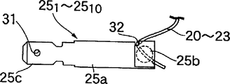
Referring to Fig. 8, each terminal component 25
1-25
20Make by conducting metal.Respectively be in the terminal component 25 fully that discord coil 20-23 connects
1-25
10Be set as L shapedly, and comprise the plate shaped base portion 25 that is fitted in the assembling tube portion 30
a, from each base portion 25
aThe clamping plate part 25 that the side is outstanding
bAnd and base portion 25
aThe other end connect in case with each binding post 27
1-27
10Connection terminals part 25
cIn splicing ear part 25
cIn be provided with connecting hole 31.Clamping plate part 25
bCan be towards base portion 25
aBending can be located at clamping plate part 25 with the engaging groove 32,33 of the engaged at end of coil 20-23
bWith base portion 25
aBetween the junction and at base portion 25
aThe end limit. Engaging groove 32,33 is set as when clamping plate 25
bDuring bending, at base portion 25
aAn end and clamping plate 25
bThe place can guarantee enough relative areas.
Connecting and terminal component 25
1-25
10During the end of corresponding coil 20-23, terminal component 25
1-25
10Be fitted into assembling tube portion 30 respectively, as shown in Figure 9.In this case, each terminal component 25
1-25
10Be fitted into and respectively assemble tube portion 30, an end of neighbouring element, just element 25
1-25
10Clamping plate part 25
bThe place has more amount outstanding from assembling tube portion 30.Therefore, be brought under the situation that engages with engaging groove 32,33 (shown in Fig. 8 b) clamping plate part 25 in the end of coil 20-23
bBending (shown in Fig. 8 c) makes coil 20-23 be clipped in clamping plate part 25
bWith substrate portion 25
aAn end between, or be inserted into the clamping plate part 25 of bending in advance in the end of coil 20-23
bWith base portion 25
aAn end between situation under, be brought into simultaneously and engaging groove 32,33 engages, make each coil 20-23 end and each terminal component 25 by fusing
1-25
10An end be electrically connected (shown in Fig. 8 d), compress base portion 25 simultaneously
aAn end and clamping plate part 25
b, make them move towards the other side.
At respective coil 20-23 and each terminal component 25
1-25
10The completed situation of electrical connection of an end under, each terminal component 25
1-25
10Push from the one end and respectively to assemble tube portion 30.At each terminal component 25
1-25
10The other end outstanding and each terminal component 25 from assembling tube portion 30
1-25
10The situation that supported by anchor clamps (not shown) and so on of an end under, binding post 27
1-27
10With inserted mode at terminal component 25
1-25
10The other end and splicing ear part 25
cConnect.
The following describes the operation of embodiment.Each terminal component 25
1-25
10The plate shaped base portion 25 that comprises the assembling tube portion 30 of the bobbin 18 of packing into
aWith from base portion 25
aThe outstanding clamping plate part 25 of an end side surface
bIn clamping plate part 25
bBent and made coil 20-23 be clipped in clamping plate part 25
bWith base portion 25
aAn end between state under, make end and the terminal component 25 of coil 20-23 by fusing
1-25
10An end connect.Therefore, the end of coil 20-23 is connected base portion 25 in the mode of fusing
aWith clamping plate part 25
bBetween.Therefore, even coil is made by magnet-wire, need not peel off the insulating bag micromicro the end of coil 20-23 and terminal component 25
1-25
10Couple together.Therefore, can be convenient to the number of attended operation and minimizing attended operation step.
Figure 10-12 illustrates a remodeling of stator, and wherein suitable with the foregoing description element portion marks with similar label.
Stator 12 ' in, 11 assembling tube portion 30 (see figure 9)s integrally are located on the bobbin 18, pass the opposite end of the core base portion 16 of stator core 14, these tube portions 30 have rectangular cross-section.Terminal component 25
1-25
11Pack into and assemble in the tube portion 30.
As shown in figure 11, respectively comprise 6 main coils 20 three groups of main coils 20 each the group an end each with three terminal components 25
1, 25
2, 25
3An end connect, separately and lead 26
1, 26
2, 26
3The binding post 27 that connects
1, 27
2, 27
3Respectively with terminal component 25
1, 25
2, 25
3The other end connect.Each other end of organizing main coil 20 respectively with each terminal component 25
4, 25
7, 25
11An end connect, with the lead 26 of ground connection
4The line post 27 that connects
4' with terminal component 25
4, 25
7, 25
11The other end connect.
As shown in figure 12, each to an end of dc coil each with terminal component 25
5, 25
6Connect, their other end interconnects.
Even in this remodeling, also can provide effect similar to the above embodiments.
Though described embodiments of the invention in detail, should understand that the present invention is not limited to the above embodiments, in the present invention's spirit that limits by following claims and scope, can make a lot of remodeling.
Claims (1)
1. the coil connecting structure of an outer rotor-type multi-pole generator, described generator comprise a plurality of coils by bobbin on a plurality of salient poles that are provided with around the stator core neighboring, a plurality of assembling tube portions integrally are located at the opposite end of passing described stator core on the described bobbin, make by conducting metal with a plurality of terminal components, and the described assembling tube portion of packing into, their opposite end is outstanding from described assembling tube portion, each described coil is connected with an end of terminal component, it is characterized in that each described terminal component comprises the plate shaped base portion of the described assembling tube portion of packing into, with the clamping plate part of giving prominence to from described base portion one end side surface, one end of each coil is connected with an end of terminal component by fusing, and described clamping plate partly bends described overhang is clipped between the end of described clamping plate part and described base portion.
Applications Claiming Priority (3)
| Application Number | Priority Date | Filing Date | Title |
|---|---|---|---|
| JP9263643A JPH11103551A (en) | 1997-09-29 | 1997-09-29 | Coil connection structure in outer rotor type multi-pole generator |
| JP263643/97 | 1997-09-29 | ||
| JP263643/1997 | 1997-09-29 |
Publications (2)
| Publication Number | Publication Date |
|---|---|
| CN1213210A CN1213210A (en) | 1999-04-07 |
| CN1102302C true CN1102302C (en) | 2003-02-26 |
Family
ID=17392341
Family Applications (1)
| Application Number | Title | Priority Date | Filing Date |
|---|---|---|---|
| CN98120831A Expired - Fee Related CN1102302C (en) | 1997-09-29 | 1998-09-29 | Coil connecting structure in outer rotor-type multi-pole generator |
Country Status (5)
| Country | Link |
|---|---|
| US (1) | US6091172A (en) |
| EP (1) | EP0905860B1 (en) |
| JP (1) | JPH11103551A (en) |
| CN (1) | CN1102302C (en) |
| DE (1) | DE69833155T8 (en) |
Cited By (1)
| Publication number | Priority date | Publication date | Assignee | Title |
|---|---|---|---|---|
| WO2010043101A1 (en) * | 2008-10-16 | 2010-04-22 | 无锡开普动力有限公司 | A connection construction for an outer rotor type generator stator winding |
Families Citing this family (31)
| Publication number | Priority date | Publication date | Assignee | Title |
|---|---|---|---|---|
| DE19748150B4 (en) * | 1997-10-31 | 2006-02-23 | Minebea Co., Ltd. | Spindle motor with contacting |
| EP1018795B1 (en) * | 1999-01-08 | 2008-03-05 | Lg Electronics Inc. | Structure of rotor for outer rotor type brushless motor |
| JP2000287402A (en) * | 1999-03-31 | 2000-10-13 | Sawafuji Electric Co Ltd | Stator for multipole generator using outer rotor |
| JP4144972B2 (en) * | 1999-05-31 | 2008-09-03 | 山洋電気株式会社 | Single bearing type permanent magnet motor and single bearing type fan motor |
| EP1107429A3 (en) * | 1999-12-01 | 2005-06-15 | Kabushiki Kaisha MORIC | Stator winding connections of a rotating electrical machine |
| JP2001169497A (en) * | 1999-12-06 | 2001-06-22 | Moriyama Manufacturing Co Ltd | Stator for ac generator |
| JP2001286090A (en) | 2000-03-30 | 2001-10-12 | Minebea Co Ltd | Motor terminal structure |
| US6538356B1 (en) * | 2000-06-28 | 2003-03-25 | Robert M. Jones | Electric machine using composite blade structure |
| JP3617810B2 (en) * | 2000-08-31 | 2005-02-09 | 三菱電機株式会社 | Rotating electric machine |
| DE10046729A1 (en) * | 2000-09-21 | 2002-05-08 | Zf Sachs Ag | Electrical machine and electrical system |
| JP3954376B2 (en) * | 2001-12-25 | 2007-08-08 | 愛三工業株式会社 | Fuel pump |
| DE10228224B3 (en) * | 2002-06-25 | 2004-02-19 | Motorenfabrik Hatz Gmbh & Co Kg | Device for cooling a power generator unit |
| JP2004040866A (en) * | 2002-07-01 | 2004-02-05 | Matsushita Electric Ind Co Ltd | Dynamo-electric motor |
| JP3894853B2 (en) * | 2002-07-11 | 2007-03-22 | 株式会社日本自動車部品総合研究所 | Rotating machine |
| WO2004030180A1 (en) | 2002-09-24 | 2004-04-08 | Sawafuji Electric Co., Ltd. | Stator for outer rotor multipole generator and method of assembling the stator |
| JP4531359B2 (en) * | 2003-07-18 | 2010-08-25 | 三菱電機株式会社 | motor |
| JP4660310B2 (en) * | 2004-11-04 | 2011-03-30 | 株式会社デンソー | Three-phase magnet generator |
| DE102007005357A1 (en) * | 2006-02-03 | 2007-10-04 | Asmo Co., Ltd., Kosai | stator |
| JP2009033836A (en) * | 2007-07-26 | 2009-02-12 | Aisin Seiki Co Ltd | Fusing structure of motor |
| JP5150930B2 (en) * | 2007-11-07 | 2013-02-27 | 本田技研工業株式会社 | Outer rotor type multi-pole generator |
| GB0808524D0 (en) * | 2008-05-12 | 2008-06-18 | Magnomatics Ltd | Magnetic pole-piece structure |
| JP5220549B2 (en) * | 2008-10-20 | 2013-06-26 | 本田技研工業株式会社 | Stator structure of outer rotor type multipolar generator |
| US8277203B2 (en) * | 2009-07-02 | 2012-10-02 | Sunonwealth Electric Machine Industry Co., Ltd. | DC fan of inner rotor type |
| DE102011054958A1 (en) * | 2011-10-31 | 2013-05-02 | Minebea Co., Ltd. | Housing of an actuator for receiving an electric motor and assembly |
| JP2013165589A (en) * | 2012-02-10 | 2013-08-22 | Denso Trim Kk | Magnet type power generator |
| JP5506836B2 (en) * | 2012-02-10 | 2014-05-28 | デンソートリム株式会社 | Magnet generator |
| CN107210640B (en) * | 2015-01-22 | 2019-07-19 | 株式会社捷太格特 | Vehicle drive unit |
| US11005325B2 (en) | 2016-07-08 | 2021-05-11 | Mitsubishi Electric Corporation | Rotating electric machine, stator of rotating electric machine, and compressor |
| CN112217356B (en) * | 2020-09-25 | 2022-12-02 | 深圳兴奇宏科技有限公司 | Method for manufacturing fan stator structure |
| US11894735B2 (en) | 2020-10-08 | 2024-02-06 | Asia Vital Components (China) Co., Ltd. | Manufacturing method of fan stator structure |
| IT202100021437A1 (en) * | 2021-08-06 | 2023-02-06 | Askoll Holding S R L A Socio Unico | Stator for three-phase permanent magnet synchronous electric motor, electric motor including said stator and method for making said stator |
Family Cites Families (10)
| Publication number | Priority date | Publication date | Assignee | Title |
|---|---|---|---|---|
| DE2235530A1 (en) * | 1972-07-20 | 1974-01-31 | Vorwerk & Co Elektrowerke Kg | STATOR, IN PARTICULAR FOR ELECTRIC MOTORS |
| US4689023A (en) * | 1985-08-27 | 1987-08-25 | The Superior Electric Company | Programmable electrical connector |
| JP2528848Y2 (en) * | 1988-09-29 | 1997-03-12 | 株式会社三協精機製作所 | Abduction type brushless motor |
| US4982124A (en) * | 1990-01-19 | 1991-01-01 | Milwaukee Electric Tool Corporation | Vibration-tolerant wire termination |
| JPH04137458U (en) * | 1991-06-18 | 1992-12-22 | 株式会社三協精機製作所 | Stator structure of small electric motor |
| JPH0624365U (en) * | 1991-11-29 | 1994-03-29 | 株式会社三協精機製作所 | Brushless motor |
| JP2881528B2 (en) * | 1992-05-15 | 1999-04-12 | ミネベア株式会社 | Flat motor stator structure |
| JPH07177720A (en) * | 1993-12-22 | 1995-07-14 | Matsushita Electric Ind Co Ltd | Brushless motor |
| JP3534889B2 (en) * | 1995-04-26 | 2004-06-07 | ミネベア株式会社 | Stator structure of rotating electric machine |
| JPH0993849A (en) * | 1995-09-20 | 1997-04-04 | Sawafuji Electric Co Ltd | Outer rotor type multipolar generator |
-
1997
- 1997-09-29 JP JP9263643A patent/JPH11103551A/en active Pending
-
1998
- 1998-09-22 US US09/158,515 patent/US6091172A/en not_active Expired - Lifetime
- 1998-09-28 DE DE69833155T patent/DE69833155T8/en active Active
- 1998-09-28 EP EP98118358A patent/EP0905860B1/en not_active Expired - Lifetime
- 1998-09-29 CN CN98120831A patent/CN1102302C/en not_active Expired - Fee Related
Cited By (1)
| Publication number | Priority date | Publication date | Assignee | Title |
|---|---|---|---|---|
| WO2010043101A1 (en) * | 2008-10-16 | 2010-04-22 | 无锡开普动力有限公司 | A connection construction for an outer rotor type generator stator winding |
Also Published As
| Publication number | Publication date |
|---|---|
| JPH11103551A (en) | 1999-04-13 |
| EP0905860B1 (en) | 2006-01-11 |
| EP0905860A2 (en) | 1999-03-31 |
| DE69833155D1 (en) | 2006-04-06 |
| CN1213210A (en) | 1999-04-07 |
| EP0905860A3 (en) | 2000-08-02 |
| US6091172A (en) | 2000-07-18 |
| DE69833155T2 (en) | 2006-07-06 |
| DE69833155T8 (en) | 2006-11-23 |
Similar Documents
| Publication | Publication Date | Title |
|---|---|---|
| CN1102302C (en) | Coil connecting structure in outer rotor-type multi-pole generator | |
| US6600244B2 (en) | Electric motor | |
| US5508571A (en) | Neutral connection for wire wound stator | |
| JP3752431B2 (en) | Rotating electric machine and manufacturing method thereof | |
| EP0917255B1 (en) | Connecting terminal for stator | |
| CN1068151C (en) | Motor termination board | |
| KR100385677B1 (en) | Alternator | |
| EP1184960B1 (en) | Vehicle-onboard AC generator | |
| US5986374A (en) | Vehicle mounted motor with rotor having ferrite magnet section with embedded permanent magnet pieces therein | |
| US20180034339A1 (en) | Stator | |
| WO2000048292A1 (en) | Motor | |
| US8067867B2 (en) | Motor with neutral bus ring connecting multiple motor coils | |
| US5789840A (en) | Endhead joint for stator bars | |
| JP4344695B2 (en) | Stator for outer rotor type multipolar generator and its assembling method | |
| JPH0739097A (en) | Motor | |
| KR20010062024A (en) | Alternator | |
| US6841904B2 (en) | Resolver terminal attachment structure | |
| JP2623438B2 (en) | Connection structure between coil wire and lead wire | |
| JP2001275291A (en) | Stator of motor | |
| JP7362794B2 (en) | Motor stator and motor | |
| JPH1070871A (en) | Stator for brushless motor | |
| US20040227417A1 (en) | Electric motor | |
| CN111106694A (en) | Electric motor with compact bus bar unit | |
| CN220653073U (en) | Motor stator wiring structure | |
| CN1340897A (en) | Stator of slewing motor |
Legal Events
| Date | Code | Title | Description |
|---|---|---|---|
| C10 | Entry into substantive examination | ||
| SE01 | Entry into force of request for substantive examination | ||
| C06 | Publication | ||
| PB01 | Publication | ||
| C14 | Grant of patent or utility model | ||
| GR01 | Patent grant | ||
| C17 | Cessation of patent right | ||
| CF01 | Termination of patent right due to non-payment of annual fee |
Granted publication date: 20030226 Termination date: 20130929 |