CN110199098B - Method and actuator for providing a variable compression ratio in an internal combustion engine - Google Patents
Method and actuator for providing a variable compression ratio in an internal combustion engine Download PDFInfo
- Publication number
- CN110199098B CN110199098B CN201780077211.7A CN201780077211A CN110199098B CN 110199098 B CN110199098 B CN 110199098B CN 201780077211 A CN201780077211 A CN 201780077211A CN 110199098 B CN110199098 B CN 110199098B
- Authority
- CN
- China
- Prior art keywords
- chamber
- shaft
- piston
- valve
- actuator
- Prior art date
- Legal status (The legal status is an assumption and is not a legal conclusion. Google has not performed a legal analysis and makes no representation as to the accuracy of the status listed.)
- Active
Links
Images


Classifications
-
- F—MECHANICAL ENGINEERING; LIGHTING; HEATING; WEAPONS; BLASTING
- F02—COMBUSTION ENGINES; HOT-GAS OR COMBUSTION-PRODUCT ENGINE PLANTS
- F02D—CONTROLLING COMBUSTION ENGINES
- F02D15/00—Varying compression ratio
- F02D15/04—Varying compression ratio by alteration of volume of compression space without changing piston stroke
-
- F—MECHANICAL ENGINEERING; LIGHTING; HEATING; WEAPONS; BLASTING
- F02—COMBUSTION ENGINES; HOT-GAS OR COMBUSTION-PRODUCT ENGINE PLANTS
- F02B—INTERNAL-COMBUSTION PISTON ENGINES; COMBUSTION ENGINES IN GENERAL
- F02B75/00—Other engines
- F02B75/04—Engines with variable distances between pistons at top dead-centre positions and cylinder heads
- F02B75/041—Engines with variable distances between pistons at top dead-centre positions and cylinder heads by means of cylinder or cylinderhead positioning
- F02B75/042—Engines with variable distances between pistons at top dead-centre positions and cylinder heads by means of cylinder or cylinderhead positioning the cylinderhead comprising a counter-piston
-
- F—MECHANICAL ENGINEERING; LIGHTING; HEATING; WEAPONS; BLASTING
- F01—MACHINES OR ENGINES IN GENERAL; ENGINE PLANTS IN GENERAL; STEAM ENGINES
- F01B—MACHINES OR ENGINES, IN GENERAL OR OF POSITIVE-DISPLACEMENT TYPE, e.g. STEAM ENGINES
- F01B31/00—Component parts, details, or accessories not provided for in, or of interest apart from, other groups
- F01B31/14—Changing of compression ratio
Abstract
In the combustion chamber of a piston internal combustion engine, there is a displaceable piston which can be moved up and down between an upper and a lower rotational position. This displacement is performed by an electrically controlled stepper motor connected to the piston by a hydraulic link comprising a hydraulic lock. During a certain number of step or step-back displacements commanded by the motor control system, the lock is deactivated and, when the displacement is over, the lock is activated by said engine control system and the moving piston is locked in a specific position commanded by the motor control system.
Description
Technical Field
The present invention relates to improving the efficiency coefficient in all types of piston internal combustion engines and also makes it possible to minimize the production of NOX (nitrogen oxides) in diesel engines.
Background
One problem to be solved in today's diesel engines is the reduction of nitrogen oxide emissions, so called NOx. The proposed solution is described and mentioned in swedish patent application No. 1500404-7, where the possibility of variable compression ratios is a prerequisite. From this proposal it can be seen that the size of the combustion chamber needs to be controlled with high accuracy and then in the preferred embodiment adapted to the amount of air supplied during the intake stroke by a freely controllable intake valve.
There are several proposed solutions for variable compression ratios, but only a few of them comprise a combustion chamber, at least the majority of which is present above the piston in the cylinder head. By placing the variable combustion chamber in the cylinder head from a dimensional point of view, efficiency enhancing solutions are provided for all types of reciprocating internal combustion engines at the same time. Diesel engines, which normally have a major part of the combustion chamber as a bowl in the piston, can be said to have the bowl move from the piston to the cylinder head, which means that the combustion chamber can be made variable in size.
Object of the Invention
The object of the present invention is to provide a solution for variable compression ratio in diesel engines, which meets the stringent and large requirements, which relates to being able to vary the size of the combustion chamber with high precision and at the same time obtain a solution which may in principle be the same for all types of piston internal combustion engines. This object is achieved by the invention by the characterizing clauses mentioned in the claims mentioned after the description.
Disclosure of Invention
The motor control system determines various actions, such as the amount of air provided to the compression ratio, the amount of fuel supplied and the time of accurate supply, the size of the combustion chamber to provide optimum efficiency and form the least NOx, etc., based on, for example, the position of the throttle.
The invention is described herein by way of a basis showing only how the adjustment and control of the combustion chamber size is performed by commands and inputs from the engine control system, and not these.
Within the combustion chamber is a movable piston which can be moved gradually up or down between upper and lower rotational positions. This displacement is performed by an electrically controlled stepper motor connected to the piston by a hydraulic link comprising a hydraulic lock. The lock is deactivated under the influence of a movement, a certain number of steps or steps, determined by the motor control system, and when the movement is completed, the lock is activated and the movable piston is locked in a certain position by the engine control system. During the combustion and expansion strokes, a lock is activated, which protects the stepper motor, its accessories and bearings from mechanical stress.
The lock is activated/deactivated by an electromagnet at the input of the engine control system. The lock comprises a so-called pressure-release hydraulic lock, which on the one hand reduces the stress on the lock and also minimizes friction, which facilitates the activation/deactivation of the lock. The steps mentioned can be very small, in millimeters, hundreds of millimeters or less. At the same time, the stepper motor allows movement with great force, which is advantageous if combustion residues on the combustion chamber walls have to be overcome. The piston is replaced after the hydraulic lock is deactivated and is easiest with a mechanical spring. The change in pressure in the combustion chamber causes the plunger to move minimally and prevent seizure.
Further description is made with the aid of the figures shown below.
Drawings
Fig. 1 schematically shows a cross section of the upper part of a diesel engine cylinder with a cylinder head, where the combustion chamber volume is adapted to small engine loads and the engine piston is in its upper rotational position after a compression stroke.
Fig. 2 schematically shows a cross section of the upper part of a diesel engine cylinder with a cylinder head, where the combustion chamber volume is adapted to the maximum engine load and the motor piston is in its upper rotational position after the compression stroke.
Fig. 3 schematically shows a cross section of the upper part of a cylinder of a diesel engine with a cylinder head, where the combustion chamber volume is adapted to the medium engine load and the piston of the engine is in its upper rotational position after the compression stroke.
Fig. 4-10 schematically illustrate how the actuator 4 replaces a piston in a combustion chamber (e.g. in a cylinder head of a diesel engine, as shown in fig. 1-3) and causes the piston to assume different positions depending on the motor load. It is emphasized that the invention can be used for all types of piston internal combustion engines.
Detailed Description
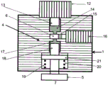
Fig. 1 shows a schematic representation of a cylinder of a diesel engine, with a cylinder head 1 and a piston 2 mounted on a crankshaft 3. An actuator 4 having a main function according to the invention is shown in fig. 4-10. The piston 5 can be controlled by input from a not shown motor control system to take different positions in the combustion chamber 7 to vary the volume of the part below the piston so that when the injector 9 injects fuel, the main part of the combustion takes place.
The different positions are locked in the hydraulic circuit 6. The outlet valve 8, controlled by a camshaft or by an actuator according to, for example, patents (SE535886C2, SE1100435a1), is schematically shown, and the inlet valve 10 is preferably, but not necessarily, opened and closed by an actuator on input from the control system of the engine, with a function according to, for example, any of the patents mentioned above. The air mass meter 11 is used to measure the amount of air introduced through the intake valve 10 during the intake stroke. The piston 2 is shown in an upper rotational position in which mechanical contact with the cylinder head including the poppet valves 8, 10 is inhibited.
Fig. 2 shows the piston 5 in its upper position, in which the size of the combustion chamber is at its maximum and the engine can, but cannot, be maximally loaded. Still, since today more or less engine load depends on how much fuel is injected, in this case exhaust emissions are today effective. It may be advantageous to provide a small bowl on the piston, the bowl being present in the piston and directly below the combustion chamber.
Fig. 3 shows a schematic view of the upper part of an engine cylinder with a cylinder head, where the volume of the combustion chamber is adapted to a medium engine load and the piston of the engine is in its upper rotational position after the compression stroke. In principle, all air from the intake stroke is forced into the volume. At the end of the compression stroke, an appropriate amount of fuel is injected to minimize NOx. The activity is controllably performed by a control system of the engine.
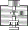
Fig. 4 shows a part of a cylinder 1 with an actuator 4 according to the invention with a stepping motor 12, which stepping motor 12 has a vertically upwardly or downwardly movable second shaft 13 extending in a second chamber 14 filled with hydraulic fluid. Furthermore, a hydraulic lock 6 is shown, comprising a valve with an opening, wherein the valve is horizontal, left or right, displaceable by a solenoid 16 or other type of electrical element in the second chamber 14 or between the second chambers 14 and below the third chamber 17 for opening and closing hydraulic fluid between the second chamber 14 and the third chamber 17, which is also filled with hydraulic fluid. Furthermore, a piston 5 is shown, which is running in a combustion chamber 7, which itself is shown in more detail in fig. 1-3. The piston has a first shaft 18, an upper part of the first shaft 18 being present in the third chamber 17 and being displaceably arranged in the third chamber 17. A first chamber 20 with a mechanical spring 19 slides the piston 5 upwards by acting between the floor of the chamber and a flange 21 present on the first shaft 18. The valve and its orifice 15 can be displaced in both directions by a double-acting solenoid or in one direction by a solenoid and in the other direction by a mechanical spring, not shown.
Fig. 5 shows the stepping motor 12, wherein the second shaft 13 is maximally displaced upwards and the piston 5 and its first shaft 18 are likewise maximally displaced upwards. The hydraulic lock of the valve 6 moving to the right closes the connection between the second chamber 14 and the third chamber 17. The stepper motor cannot influence the piston 5 in this position.
Fig. 6 shows that the hydraulic lock deactivated by the solenoid resets the valve 6 to the left, so that its opening 15 forms a connection between the hydraulic fluid filling the second chamber 14 and the third chamber 17.
Fig. 7 shows the stepper motor 12 returning the second shaft 13 downwards, pushing hydraulic fluid from the second chamber 14 through the opening 15 in the valve 6 towards the third chamber 17, pushing the first shaft 18 and its piston 5 downwards under compression of the spring 19. Thus, the combustion chamber, not directly shown, is reduced.
Fig. 8 shows the solenoid 16 with the valve 6 in a position in which the connection between the second chamber 14 and the solenoid 16 is opened, so that the hydraulic lock is activated. The piston 5 cannot move either up or down.
Fig. 9 shows that the hydraulic lock has been deactivated.
Fig. 10 shows a position in which the stepper motor 12 has moved the second shaft 13 upwards, whereby hydraulic fluid is pressed from the third chamber 17 to the second chamber 14 by the action of the spring 19 and the piston 5 of the first shaft 18 has moved upwards.
Measures taken by the person skilled in the art, such as the adaptation of the hydraulic fluid to the engine oil, how the volume of the hydraulic fluid remains substantially constant, the choice and placement of the engine control system, the dimensioning of the combustion chamber, etc., are not described. Engine control systems are obvious today, so there is no mention in the claims that the action of the electromagnet and the stepping motor is controlled by the engine control system.
Claims (6)
1. A method of controlling the size of a combustion chamber (7) by means of an actuator (4) in a cylinder head (1) of a piston combustion engine, which comprises:
a combustion chamber (7);
a piston (5), said piston (5) being vertically displaceable and arranged in said combustion chamber (7); and
an actuator (4), the actuator (4) comprising:
a first chamber (20) having a first shaft (18), the first shaft (18) extending through the first chamber (20) and being connected with the piston (5), the first shaft (18) having a flange (21) and a spring (19) disposed in the first chamber (20), the spring (19) acting between the flange (21) and a floor of the first chamber (20) to exert a force on the piston (5) in an upward direction;
a second chamber (14) and a third chamber (17) filled with hydraulic fluid and separated by a valve (6) having an opening (15), wherein the valve is horizontally resettable by a solenoid (16),
a stepper motor (12) and a second shaft (13), the second shaft (13) being vertically displaceable in the second chamber (14) by the stepper motor (12),
wherein an upper portion of the first shaft (18) extends into the third chamber (17) for the hydraulic fluid to act thereon,
the method comprises varying the size of the combustion chamber (7) by:
displacing the valve (6) by means of the electromagnet such that the opening of the valve connects the second chamber (14) and the third chamber (17), an
Displacing the second shaft (13) using the stepper motor (12) to flow the hydraulic fluid between the second chamber (14) and the third chamber (17) to reset the first shaft (18) and the piston (5) connected thereto.
2. Method according to claim 1, characterized in that when the second shaft (13) is displaced downwards by the stepper motor, the hydraulic fluid is forced to displace from the second chamber (14) to the third chamber (17), wherein the first shaft (18) with its piston (5) is displaced downwards together with its piston (5), compressing the spring (19) while reducing the size of the combustion chamber until the end of the return of the second shaft (13).
3. Method according to claim 1 or 2, characterized in that when the resetting of the second shaft (13) is finished, the valve is displaced together with its opening so that the opening no longer connects the second chamber (14) and the third chamber (17) and the piston (5) can no longer be displaced.
4. Method according to claim 1, characterized in that when the stepper motor moves the second shaft (13) upwards, the hydraulic fluid is forced to flow from the third chamber (17) to the second chamber (14) by the spring (19) acting on the flange (21) of the first shaft (18), wherein the piston (5) moves upwards while the spring (19) is expanding, as the size of the combustion chamber increases until the displacement of the second shaft (13) has ended.
5. Method according to claim 1 or 4, characterized in that when the displacement of the second shaft (13) is finished, the valve is displaced together with its opening, so that the opening no longer connects the second chamber (14) and the third chamber (17), so that the piston (5) can no longer be displaced.
6. An actuator in a piston combustion engine comprising a combustion chamber (7), and a vertically displaceable piston (5) arranged in the combustion chamber, the actuator comprising:
a first chamber (20);
a first shaft (18) connected with the piston (5), extending through the first chamber (20) and having a flange (21) arranged in the first chamber,
a spring (19) arranged between the flange (21) and the floor of the first chamber (20),
a second chamber (14) and a third chamber (17),
a valve (6) having an opening (15) between the second chamber (14) and the third chamber (17),
an electromagnet (16) arranged to actuate the valve (6),
a second shaft (13) displaceably arranged in the second chamber (14), and
a stepper motor (12) arranged to displace the second shaft (13),
wherein an upper portion of the first shaft (18) extends into the third chamber (17) to be acted upon by hydraulic fluid to change the size of the combustion chamber (7) by:
-resetting the first shaft (18) and the piston (5) connected thereto by displacing the valve (6) with its opening connecting the second chamber (14) and the third chamber (17), and by displacing the second shaft (13) using the stepper motor (12) to flow the hydraulic fluid between the second chamber (14) and the third chamber (17).
Applications Claiming Priority (3)
| Application Number | Priority Date | Filing Date | Title |
|---|---|---|---|
| SE1600344 | 2016-12-14 | ||
| SE1600344-4 | 2016-12-14 | ||
| PCT/SE2017/000049 WO2018111167A1 (en) | 2016-12-14 | 2017-12-14 | Method for providing variable compression ratio in an internal combustion engine and actuator for said method |
Publications (2)
| Publication Number | Publication Date |
|---|---|
| CN110199098A CN110199098A (en) | 2019-09-03 |
| CN110199098B true CN110199098B (en) | 2021-07-06 |
Family
ID=62559700
Family Applications (1)
| Application Number | Title | Priority Date | Filing Date |
|---|---|---|---|
| CN201780077211.7A Active CN110199098B (en) | 2016-12-14 | 2017-12-14 | Method and actuator for providing a variable compression ratio in an internal combustion engine |
Country Status (9)
| Country | Link |
|---|---|
| US (1) | US10641167B2 (en) |
| EP (1) | EP3555445A4 (en) |
| JP (1) | JP7154212B2 (en) |
| KR (1) | KR102255139B1 (en) |
| CN (1) | CN110199098B (en) |
| BR (1) | BR112019012004A2 (en) |
| MX (1) | MX2019007039A (en) |
| RU (1) | RU2720896C1 (en) |
| WO (1) | WO2018111167A1 (en) |
Families Citing this family (6)
| Publication number | Priority date | Publication date | Assignee | Title |
|---|---|---|---|---|
| US11428174B2 (en) | 2018-03-23 | 2022-08-30 | Lawrence Livermore National Security, Llc | System and method for control of compression in internal combustion engine via compression ratio and elastic piston |
| SE543587C2 (en) * | 2018-12-14 | 2021-04-06 | Hedman Ericsson Patent Ab | Method for producing a high exhaust temperature at engine part load in a diesel engine and apparatus for carrying out the method |
| SE543474C2 (en) * | 2019-02-01 | 2021-03-02 | Hedman Ericsson Patent Ab | Method for producing variable compression ratio in internal combustion engine and device for the method |
| US11421626B2 (en) | 2019-10-16 | 2022-08-23 | Raytheon Technologies Corporation | Nozzle-to-engine mount reinforcement through which mounting fasteners are visible |
| US11136916B1 (en) * | 2020-10-06 | 2021-10-05 | Canadavfd Corp (Ltd) | Direct torque control, piston engine |
| WO2022169824A1 (en) * | 2021-02-05 | 2022-08-11 | Lawrence Livermore National Security, Llc | System and method for control of compression in internal combustion engine via compression ratio and elastic piston |
Citations (10)
| Publication number | Priority date | Publication date | Assignee | Title |
|---|---|---|---|---|
| US1612494A (en) * | 1924-11-04 | 1926-12-28 | Henry H Cutler | Internal-combustion engine |
| US1680710A (en) * | 1924-03-05 | 1928-08-14 | John White | Cylinder of internal-combustion engines |
| DE2937619A1 (en) * | 1979-09-18 | 1981-04-02 | Volkswagenwerk Ag, 3180 Wolfsburg | Compression-ratio control for four-stroke IC engine - has hydraulic adjustment piston moving secondary piston that alters volume of combustion chamber |
| JPS59188056A (en) * | 1983-03-08 | 1984-10-25 | Mazda Motor Corp | Variable compression ratio engine |
| CN101016863A (en) * | 2007-03-02 | 2007-08-15 | 袁辉 | Variable compression ratio device of piston reciprocating internal combustion engine |
| CN101109321A (en) * | 2007-08-08 | 2008-01-23 | 陈晨 | Self-adaption compression ratio variable engine |
| CN100394000C (en) * | 2003-02-18 | 2008-06-11 | 履带拖拉机股份有限公司 | Combustion engine variable compression ratio apparatus and method |
| JP2008180235A (en) * | 2000-11-29 | 2008-08-07 | Kenneth W Cowans | High efficiency engine with variable compression ratio and charge |
| CN101375040A (en) * | 2006-01-26 | 2009-02-25 | 维亚内·拉比 | Pressure device for a variable compression ratio engine |
| CN102165197A (en) * | 2008-09-26 | 2011-08-24 | 日立空调·家用电器株式会社 | Screw compressor |
Family Cites Families (15)
| Publication number | Priority date | Publication date | Assignee | Title |
|---|---|---|---|---|
| SU947450A1 (en) * | 1980-04-23 | 1982-07-30 | Украинский Институт Инженеров Водного Хозяйства | Ic engine with automatic control of compression degree |
| JPH02271036A (en) * | 1989-04-12 | 1990-11-06 | Fuji Heavy Ind Ltd | Compression ratio control device of engine |
| JPH10196424A (en) * | 1996-12-28 | 1998-07-28 | Toyota Central Res & Dev Lab Inc | Compression ignition type combustion method for air-fuel mixture, and compression ignition type piston internal combustion engine for air-fuel mixture |
| JP3577932B2 (en) * | 1998-02-19 | 2004-10-20 | トヨタ自動車株式会社 | Variable valve gear |
| US6578533B1 (en) * | 2001-11-29 | 2003-06-17 | The United States Of America As Represented By The Administrator Of The U.S. Environmental Protection Agency | Controlled homogeneous-charge, compression-ignition engine |
| US6708655B2 (en) * | 2002-04-15 | 2004-03-23 | Caterpillar Inc | Variable compression ratio device for internal combustion engine |
| RU2289703C2 (en) * | 2002-10-11 | 2006-12-20 | Военный автомобильный институт | Stepless compression ratio changer |
| JP2005256734A (en) | 2004-03-11 | 2005-09-22 | Fuji Heavy Ind Ltd | Cylinder injection engine |
| FR2902145B1 (en) * | 2006-06-07 | 2008-08-08 | Renault Sas | METHOD AND SYSTEM FOR CONTINUOUSLY CONTROLLING THE POSITION OF A COMPRESSION RATE CHANGE ACTUATOR OF A THERMAL ENGINE |
| JP2008128227A (en) | 2006-11-18 | 2008-06-05 | Shuichi Kitamura | Super-high efficiency four-cycle internal combustion engine |
| US20090223491A1 (en) * | 2008-03-05 | 2009-09-10 | Ahmed Syed | Variable compression ratio engine |
| US8418663B2 (en) * | 2009-03-24 | 2013-04-16 | Radu Oprea | Cam actuation mechanism with application to a variable-compression internal-combustion engine |
| US20110197859A1 (en) * | 2011-04-23 | 2011-08-18 | Wilson Kelce S | Dynamically Altering Piston Displacement |
| SE535886C2 (en) | 2011-06-03 | 2013-02-05 | Ase Alternative Solar Energy Engine Ab | Pressure Pulse Generator |
| KR101510335B1 (en) | 2013-10-30 | 2015-04-08 | 현대자동차 주식회사 | Variable compression ratio device |
-
2017
- 2017-12-14 US US16/468,824 patent/US10641167B2/en active Active
- 2017-12-14 KR KR1020197020316A patent/KR102255139B1/en active IP Right Grant
- 2017-12-14 CN CN201780077211.7A patent/CN110199098B/en active Active
- 2017-12-14 JP JP2019530474A patent/JP7154212B2/en active Active
- 2017-12-14 WO PCT/SE2017/000049 patent/WO2018111167A1/en unknown
- 2017-12-14 MX MX2019007039A patent/MX2019007039A/en unknown
- 2017-12-14 BR BR112019012004-1A patent/BR112019012004A2/en unknown
- 2017-12-14 RU RU2019121665A patent/RU2720896C1/en active
- 2017-12-14 EP EP17880784.8A patent/EP3555445A4/en active Pending
Patent Citations (10)
| Publication number | Priority date | Publication date | Assignee | Title |
|---|---|---|---|---|
| US1680710A (en) * | 1924-03-05 | 1928-08-14 | John White | Cylinder of internal-combustion engines |
| US1612494A (en) * | 1924-11-04 | 1926-12-28 | Henry H Cutler | Internal-combustion engine |
| DE2937619A1 (en) * | 1979-09-18 | 1981-04-02 | Volkswagenwerk Ag, 3180 Wolfsburg | Compression-ratio control for four-stroke IC engine - has hydraulic adjustment piston moving secondary piston that alters volume of combustion chamber |
| JPS59188056A (en) * | 1983-03-08 | 1984-10-25 | Mazda Motor Corp | Variable compression ratio engine |
| JP2008180235A (en) * | 2000-11-29 | 2008-08-07 | Kenneth W Cowans | High efficiency engine with variable compression ratio and charge |
| CN100394000C (en) * | 2003-02-18 | 2008-06-11 | 履带拖拉机股份有限公司 | Combustion engine variable compression ratio apparatus and method |
| CN101375040A (en) * | 2006-01-26 | 2009-02-25 | 维亚内·拉比 | Pressure device for a variable compression ratio engine |
| CN101016863A (en) * | 2007-03-02 | 2007-08-15 | 袁辉 | Variable compression ratio device of piston reciprocating internal combustion engine |
| CN101109321A (en) * | 2007-08-08 | 2008-01-23 | 陈晨 | Self-adaption compression ratio variable engine |
| CN102165197A (en) * | 2008-09-26 | 2011-08-24 | 日立空调·家用电器株式会社 | Screw compressor |
Also Published As
| Publication number | Publication date |
|---|---|
| MX2019007039A (en) | 2019-08-16 |
| WO2018111167A1 (en) | 2018-06-21 |
| EP3555445A1 (en) | 2019-10-23 |
| EP3555445A4 (en) | 2020-07-29 |
| BR112019012004A2 (en) | 2019-10-29 |
| JP7154212B2 (en) | 2022-10-17 |
| KR20190091351A (en) | 2019-08-05 |
| CN110199098A (en) | 2019-09-03 |
| US20190301362A1 (en) | 2019-10-03 |
| RU2720896C1 (en) | 2020-05-13 |
| KR102255139B1 (en) | 2021-05-21 |
| JP2020502408A (en) | 2020-01-23 |
| US10641167B2 (en) | 2020-05-05 |
Similar Documents
| Publication | Publication Date | Title |
|---|---|---|
| CN110199098B (en) | Method and actuator for providing a variable compression ratio in an internal combustion engine | |
| US4721247A (en) | High pressure unit fuel injector | |
| US7341028B2 (en) | Hydraulic valve actuation systems and methods to provide multiple lifts for one or more engine air valves | |
| CN107110095B (en) | The high-pressure fuel feed device of internal combustion engine | |
| GB2340192A (en) | I.c. engine fuel injection pump-nozzle unit with piezoelectrically actuated control valve | |
| US5651501A (en) | Fluid damping of a valve assembly | |
| EP1607593B1 (en) | Exhaust valve drive control method and device | |
| US7178491B2 (en) | Control system and method for engine valve actuator | |
| WO2014113134A1 (en) | Methods of operation of fuel injectors with intensified fuel storage | |
| US7509948B1 (en) | Variable displacement pump with an anti-stiction device | |
| US20100180875A1 (en) | Seating control device for a valve for a split-cycle engine | |
| US6799552B2 (en) | System and method for controlling engine operation | |
| US6935580B2 (en) | Valve assembly having multiple rate shaping capabilities and fuel injector using same | |
| US6880769B2 (en) | Electronically-controlled fuel injector | |
| GB2351772A (en) | Pressure-intensifying hydraulically-actuated electronically-controlled fuel injection system with individual mechanical unit pumps | |
| US6520150B1 (en) | Fuel injector assembly and internal combustion engine including same | |
| JP2004515708A (en) | Fuel injection device for internal combustion engines | |
| JP2005517864A (en) | Fuel injection device for an internal combustion engine | |
| JPS60259713A (en) | Electronic control system hydraulic valve unit for internal-combustion engine | |
| JP6319235B2 (en) | Fuel injection device | |
| CN111051681A (en) | Device for controlling an injector | |
| CN113396275B (en) | Method for providing variable compression ratio in internal combustion engine and device therefor | |
| JPS6339793B2 (en) | ||
| GB2369860A (en) | Method of injecting fuel with piezo-actuation of control valves allowing multiple or timed injection | |
| JPS59155568A (en) | Fuel injection device for internal-combustion engine |
Legal Events
| Date | Code | Title | Description |
|---|---|---|---|
| PB01 | Publication | ||
| PB01 | Publication | ||
| SE01 | Entry into force of request for substantive examination | ||
| SE01 | Entry into force of request for substantive examination | ||
| GR01 | Patent grant | ||
| GR01 | Patent grant |