CN1101915C - Lighting device - Google Patents
Lighting device Download PDFInfo
- Publication number
- CN1101915C CN1101915C CN97195730A CN97195730A CN1101915C CN 1101915 C CN1101915 C CN 1101915C CN 97195730 A CN97195730 A CN 97195730A CN 97195730 A CN97195730 A CN 97195730A CN 1101915 C CN1101915 C CN 1101915C
- Authority
- CN
- China
- Prior art keywords
- lampshade
- lamp socket
- lighting device
- basis
- light source
- Prior art date
- Legal status (The legal status is an assumption and is not a legal conclusion. Google has not performed a legal analysis and makes no representation as to the accuracy of the status listed.)
- Expired - Fee Related
Links
- 230000001012 protector Effects 0.000 abstract 3
- 238000009434 installation Methods 0.000 description 30
- 239000007788 liquid Substances 0.000 description 15
- 239000002689 soil Substances 0.000 description 15
- 230000002349 favourable effect Effects 0.000 description 10
- 238000007667 floating Methods 0.000 description 9
- 238000010276 construction Methods 0.000 description 8
- 230000000694 effects Effects 0.000 description 8
- 238000007789 sealing Methods 0.000 description 7
- 230000006378 damage Effects 0.000 description 6
- 238000004519 manufacturing process Methods 0.000 description 6
- 238000000034 method Methods 0.000 description 6
- 239000000463 material Substances 0.000 description 5
- 239000004033 plastic Substances 0.000 description 4
- 229920003023 plastic Polymers 0.000 description 4
- XLYOFNOQVPJJNP-UHFFFAOYSA-N water Substances O XLYOFNOQVPJJNP-UHFFFAOYSA-N 0.000 description 4
- 102000002322 Egg Proteins Human genes 0.000 description 3
- 108010000912 Egg Proteins Proteins 0.000 description 3
- 239000004698 Polyethylene Substances 0.000 description 3
- 230000015572 biosynthetic process Effects 0.000 description 3
- 239000011449 brick Substances 0.000 description 3
- 210000003278 egg shell Anatomy 0.000 description 3
- 238000005516 engineering process Methods 0.000 description 3
- 238000012856 packing Methods 0.000 description 3
- 230000008569 process Effects 0.000 description 3
- 208000027418 Wounds and injury Diseases 0.000 description 2
- 230000008859 change Effects 0.000 description 2
- 230000006835 compression Effects 0.000 description 2
- 238000007906 compression Methods 0.000 description 2
- 230000005611 electricity Effects 0.000 description 2
- 238000011010 flushing procedure Methods 0.000 description 2
- 230000005484 gravity Effects 0.000 description 2
- 208000014674 injury Diseases 0.000 description 2
- 238000007639 printing Methods 0.000 description 2
- 238000003860 storage Methods 0.000 description 2
- 241000931705 Cicada Species 0.000 description 1
- 241000692569 Stylephorus chordatus Species 0.000 description 1
- 230000009471 action Effects 0.000 description 1
- 230000000295 complement effect Effects 0.000 description 1
- 230000007797 corrosion Effects 0.000 description 1
- 238000005260 corrosion Methods 0.000 description 1
- 230000008878 coupling Effects 0.000 description 1
- 238000010168 coupling process Methods 0.000 description 1
- 238000005859 coupling reaction Methods 0.000 description 1
- 238000005520 cutting process Methods 0.000 description 1
- 238000010586 diagram Methods 0.000 description 1
- 238000003912 environmental pollution Methods 0.000 description 1
- 239000011521 glass Substances 0.000 description 1
- 238000005286 illumination Methods 0.000 description 1
- 238000009413 insulation Methods 0.000 description 1
- 230000003287 optical effect Effects 0.000 description 1
- -1 polyethylene Polymers 0.000 description 1
- 229920000573 polyethylene Polymers 0.000 description 1
- 238000007781 pre-processing Methods 0.000 description 1
- 230000035945 sensitivity Effects 0.000 description 1
- 238000007493 shaping process Methods 0.000 description 1
- 239000007787 solid Substances 0.000 description 1
- 230000007704 transition Effects 0.000 description 1
- 239000003643 water by type Substances 0.000 description 1
- 238000003466 welding Methods 0.000 description 1
Images


Classifications
-
- F—MECHANICAL ENGINEERING; LIGHTING; HEATING; WEAPONS; BLASTING
- F21—LIGHTING
- F21V—FUNCTIONAL FEATURES OR DETAILS OF LIGHTING DEVICES OR SYSTEMS THEREOF; STRUCTURAL COMBINATIONS OF LIGHTING DEVICES WITH OTHER ARTICLES, NOT OTHERWISE PROVIDED FOR
- F21V21/00—Supporting, suspending, or attaching arrangements for lighting devices; Hand grips
- F21V21/02—Wall, ceiling, or floor bases; Fixing pendants or arms to the bases
- F21V21/04—Recessed bases
-
- F—MECHANICAL ENGINEERING; LIGHTING; HEATING; WEAPONS; BLASTING
- F21—LIGHTING
- F21S—NON-PORTABLE LIGHTING DEVICES; SYSTEMS THEREOF; VEHICLE LIGHTING DEVICES SPECIALLY ADAPTED FOR VEHICLE EXTERIORS
- F21S8/00—Lighting devices intended for fixed installation
- F21S8/03—Lighting devices intended for fixed installation of surface-mounted type
- F21S8/032—Lighting devices intended for fixed installation of surface-mounted type the surface being a floor or like ground surface, e.g. pavement
-
- F—MECHANICAL ENGINEERING; LIGHTING; HEATING; WEAPONS; BLASTING
- F21—LIGHTING
- F21V—FUNCTIONAL FEATURES OR DETAILS OF LIGHTING DEVICES OR SYSTEMS THEREOF; STRUCTURAL COMBINATIONS OF LIGHTING DEVICES WITH OTHER ARTICLES, NOT OTHERWISE PROVIDED FOR
- F21V15/00—Protecting lighting devices from damage
-
- F—MECHANICAL ENGINEERING; LIGHTING; HEATING; WEAPONS; BLASTING
- F21—LIGHTING
- F21V—FUNCTIONAL FEATURES OR DETAILS OF LIGHTING DEVICES OR SYSTEMS THEREOF; STRUCTURAL COMBINATIONS OF LIGHTING DEVICES WITH OTHER ARTICLES, NOT OTHERWISE PROVIDED FOR
- F21V17/00—Fastening of component parts of lighting devices, e.g. shades, globes, refractors, reflectors, filters, screens, grids or protective cages
- F21V17/06—Fastening of component parts of lighting devices, e.g. shades, globes, refractors, reflectors, filters, screens, grids or protective cages the fastening being onto or by the lampholder
-
- F—MECHANICAL ENGINEERING; LIGHTING; HEATING; WEAPONS; BLASTING
- F21—LIGHTING
- F21V—FUNCTIONAL FEATURES OR DETAILS OF LIGHTING DEVICES OR SYSTEMS THEREOF; STRUCTURAL COMBINATIONS OF LIGHTING DEVICES WITH OTHER ARTICLES, NOT OTHERWISE PROVIDED FOR
- F21V17/00—Fastening of component parts of lighting devices, e.g. shades, globes, refractors, reflectors, filters, screens, grids or protective cages
- F21V17/10—Fastening of component parts of lighting devices, e.g. shades, globes, refractors, reflectors, filters, screens, grids or protective cages characterised by specific fastening means or way of fastening
- F21V17/102—Fastening of component parts of lighting devices, e.g. shades, globes, refractors, reflectors, filters, screens, grids or protective cages characterised by specific fastening means or way of fastening using gravity or suction
-
- F—MECHANICAL ENGINEERING; LIGHTING; HEATING; WEAPONS; BLASTING
- F21—LIGHTING
- F21V—FUNCTIONAL FEATURES OR DETAILS OF LIGHTING DEVICES OR SYSTEMS THEREOF; STRUCTURAL COMBINATIONS OF LIGHTING DEVICES WITH OTHER ARTICLES, NOT OTHERWISE PROVIDED FOR
- F21V27/00—Cable-stowing arrangements structurally associated with lighting devices, e.g. reels
- F21V27/02—Cable inlets
-
- F—MECHANICAL ENGINEERING; LIGHTING; HEATING; WEAPONS; BLASTING
- F21—LIGHTING
- F21V—FUNCTIONAL FEATURES OR DETAILS OF LIGHTING DEVICES OR SYSTEMS THEREOF; STRUCTURAL COMBINATIONS OF LIGHTING DEVICES WITH OTHER ARTICLES, NOT OTHERWISE PROVIDED FOR
- F21V3/00—Globes; Bowls; Cover glasses
-
- F—MECHANICAL ENGINEERING; LIGHTING; HEATING; WEAPONS; BLASTING
- F21—LIGHTING
- F21W—INDEXING SCHEME ASSOCIATED WITH SUBCLASSES F21K, F21L, F21S and F21V, RELATING TO USES OR APPLICATIONS OF LIGHTING DEVICES OR SYSTEMS
- F21W2131/00—Use or application of lighting devices or systems not provided for in codes F21W2102/00-F21W2121/00
- F21W2131/10—Outdoor lighting
- F21W2131/109—Outdoor lighting of gardens
Abstract
A lighting device (1') contains a light holder (2'), which can be positioned on a support (16') and is designed to hold a light source (4), and a light protector (3) surrounding the said light source and removably connected to the light holder (2'). The light protector covers both the light source (4) projecting from the support (16') and the light-holder regions likewise projecting therefrom in such a manner that, when the device is assembled, substantially only the light protector is visible.
Description
The present invention relates to one and can the lamp socket of placing on the basis be installed, lamp socket has an outer lamp socket border and has one to be used for fixing in installment state from the lamp socket top of the outstanding light source in basis is installed in the mesozone; The lampshade of removably fixing on lamp socket, described lampshade cover light source and from outstanding lamp socket district, basis is installed, remain on installment state and can only see lampshade.
From this lighting device of DE-AS1157703 cicada, in addition, this class lighting device also knows from DE-U-8911879, and in this kind lighting device, lampshade comprises the slit of many outlets as the light that sends from light source.Other that lighting device is set in the scope in these light outlet slits can approaching from the outside structure division.In addition, optical lens and be used for lampshade is fixed on trip bolt on the lamp socket is for example arranged.The shortcoming of this lighting device is, must be expensively so definite on manufacturing technology at the light outlet gap size on the lampshade, must get at the fastener that is used in lampshade, so that install.The influence that its structural configuration sustains damage lighting device easily and is subjected to being determined by weather.Another shortcoming is that the structure of its single part is all complicated on textural and mounting technique.
The object of the present invention is to provide a kind of both can interior zone with can be externally the lighting device that uses of zone, it also can prevent damage in addition.
For realizing above-mentioned purpose of the present invention, the invention provides a kind of lighting device, described lighting device comprises: one can install the lamp socket of placing on the basis, and lamp socket has an outer lamp socket border and has one to be used for fixing in installment state from the lamp socket top of the outstanding light source in basis is installed in the mesozone; The lampshade of on lamp socket, removably fixing, described lampshade covers light source and from the lamp socket district that give prominence on the basis is installed, make and to see lampshade in installment state, it is characterized in that, lampshade has the lampshade flange of a formation one lampshade opening, and the supporting web that described lampshade flange is provided with towards the inner space of lampshade surrounds described lamp socket border.
According to the present invention, installment state at lighting device, it is from installing outstanding lamp socket district, basis, same also have from the outstanding light source in basis is installed, and the structure division that also is arranged on the lampshade on the lamp socket sometimes in addition all will so be covered, so that can only see the surface or the lampshade wall that play a part actual lid of lampshade or lampshade basically in installment state.Particularly in installment state, lampshade want all or similar all surround lighting devices from the structure division that give prominence on the basis is installed.Crossing the covering fully that outstanding lamp socket district, basis is installed can realize thus, promptly has towards the lampshade of the lampshade flange that the basis the is installed outer lamp socket border perpendicular to the circumferential encirclement lamp socket of longitudinal axis along lamp socket.Preferably the lamp socket border crosses that the basis is installed is outstanding and play a part to be used for the sealing of the inner space of lighting device by it.The lampshade flange forms the central opening of lampshade, and it is used to admit from basis outstanding lamp socket district and light source are installed.Preferably the lampshade flange is the part of the integral body of ready-made lampshade.Preferably the lampshade flange shape is surrounded the lamp socket border with flushing ordinatedly or.In the case, when being placed on lampshade on the lamp socket, the lamp socket border also plays a part auxiliary centering in addition, and simplifies the specialty installation of lighting device in addition thus.In addition, this form fit has formed enough sealings of the inner space of lighting device in many cases.Being positioned at the sealing fully that lamp socket district in addition, basis is installed can get help by a supporting web that is shaped on the lampshade flange, and this supporting web is made the edge of a wing on lamp socket border and its shape is surrounded with flushing suitably or.The supporting web towards the lampshade inner space at the lampshade open region makes it to bear well the power that particularly acts on the lampshade on its outer surface that acts on.In addition, satisfactory when how the supporting web towards inside can not influence lampshade in installment state yet, the spatial form of can the outside seeing.Just can guarantee that in this way the structure division that need not add is just accomplished to protect each part of lighting device not to be mechanically damaged effectively especially, worn and torn, influence on every side and possible electrification root and improve the durability of lighting device thus.Therefore also for example can all cover and be contained in being used on the lamp socket lighting device is placed on the fixture of installing on the basis regularly, and can prevent corrosion or other fret wear and undesirable dismounting effectively.In all cases, lampshade all externally cover lamp socket usually can be approaching from the outside zone and light source, and the structure division of the sensitivity of illumination apparatus also has special excellent protection and sealing function thus.
All make usually in the lampshade wall district that plays intrinsic lid effect of lampshade does not have aperture.At this moment, lampshade structurally preferably so cooperates with lamp socket, so that lampshade is admitted the part that will cover of lighting device and used the opening border of lampshade opening tangent with the installation surface that the basis is installed by passing the lampshade opening at confined state.In such a way basically only to see lampshade.It can reach like this, and promptly lampshade or its opening border can only be placed directly in installment state and install on the surface.In another kind of version, lampshade has any to stretch into (for example when using liquid as the installation basis) in the installation basis a little.The present invention also comprises a kind of like this possibility, promptly in order to guarantee the mobile space of lampshade with respect to necessity that the surface is installed, its edge of opening is tangent with the installation surface with little spacing, like this, lampshade might have an installation that can not damage, and especially when air spots is installed, lampshade can also arrive the installation site of its regulation in the clear.Since lamp socket install therewith mobile space accordingly, perhaps lid not, structure height that the basis surpass to be installed is very little, can ignore, therefore, can guarantee in the case, basically can only see lampshade in installment state, all the other parts of lighting device can be covered basically fully.In addition, particularly when basic out-of-flatness is installed, the covering effect of lampshade can be by installing surface (glass for example, soil) itself gets help, so that because installation the mobile space noted earlier and zone that may be not do not covered by lampshade can cover with these unevenness of directly surrounding lamp sockets.
All that can enough stably be placed the installation unit of lighting device or mounting foundation in installment state and running status and can be interpreted as the basis is installed.At this moment, lighting device can be supported by additional fastener in the supporting of installing on the basis.The installation basis of proper is for example comparatively robust is as wall, indoor ceiling or wall.Lamp socket can be put into this installation basis or be placed on these surfaces that basis is installed, and at this moment, crosses the light source and the outstanding lamp socket district of giving prominence on the installation surface and covers with lampshade.Other installation basis is for for example soil or liquid, and in liquid, lamp socket is put into as floating element, and as floating element, the material of lamp socket self-evidently will so be selected, and promptly its proportion is less than the proportion of corresponding liquid.In addition, this " floating " lighting device will make liquid not see through by suitable servicing unit.
Because the visible part of lighting device is reduced to just light-emitting area basically in installment state, i.e. the visible surface of lampshade, therefore, lighting device also is particularly suitable for the beautiful device of profile in scenic spot, garden furniture, waters, the pond equipment.When lighting device was used as floating element, liquid surface was installed the surface exactly.
Lamp socket and lampshade will so construct and install, so that lamp socket for example is installed in it trip bolt of installing on the basis with the structure division and the installation auxiliary device in case of necessity that are included in wherein, can not be seen from the outside in the installment state of lighting device.In such a way, lighting device can only be seen the lampshade of printing opacity basically in installment state.The invisibility of remaining structure division is given the image of lighting device with good looking appearance in installment state.
Because what need be used for canopy-protected only is lampshade, the lighting device that therefore has few mounting cost both can be used for exterior lighting, also can be used for the interior lighting of enclosure space.
In a preferred construction form, lamp socket can be placed on when the installation of lighting device at least in part to be installed in the basis.In such a way, the manufacturing of lampshade keeps irrelevant with the structure height of different mounting conditions and lamp socket with configuration.This just allows to be used for a kind of lampshade the lamp socket of different size omnipotently, and thus, the kind of the structure division that is used for different lighting devices that store can remain a spot of economically.Lamp socket can for example be placed in soil, pond, garden or other liquid container.So soil surface or liquid surface have formed the surface is installed.In the case, the installation basis (for example soil, liquid) of encirclement lamp socket has formed the sufficiently stable supporting of lighting device and has fixed.Simultaneously, the basis is installed and assists the injury protection that is used for lamp socket and has structure division wherein sometimes.
The structure height of lamp socket will adapt to different structural conditions.For firm installation basis (for example pavement, wall), can adopt with respect to its securing member has shorter holder structure height.At this moment, some trip bolts pass the lamp socket hole, so that it firmly is connected with the installation basis.The basis is being installed or ground (for example soil, water) is softer or loose or installing in the basis and have under the situation of the admittance passage that is used for lamp socket of giving a farfetched interpretation, is wishing that then lamp socket has bigger structure height, position stability so that lamp socket can be put into the installation basis.For stable, lamp socket preferably is placed in the ground with the major part of structure height, and (for example ground, horizontal plane) the outstanding zone, installation surface of crossing of lamp socket then covers with lampshade by above-described mode in installment state.The trip bolt that is used for fastening short lamp socket can replace with the soil that surrounds lamp socket, water or packing material when higher at holder structure.Because bigger holder structure height, its center of gravity will installed surface following (=the inside, basis is being installed), so that only just lamp socket can be resisted with above-mentioned soil or packing material and be placed in the installation basis with tumbling.
The whole aesthetic appearance of lighting device can be strengthened by the corresponding configuration of lampshade.In a preferred construction form, lampshade is made rotational symmetric, and is for example spherical or columniform.In addition, also rotational symmetric lampshade can be made the configuration of eggshell state.Particularly, the sphere of lampshade and eggshell shape can be born the external force that acts on the lampshade well.Also can form the additional injury protection of lighting device in such a way.
In another preferred construction form, lampshade is made polygon.No matter be the polygonal or rotational symmetric configuration of lampshade, its side towards the direction that the surface is installed can be made by taper and shrink, can improve the interesting outward appearance of lighting device thus.
Lampshade is for example used the plastics manufacturing of dimensionally stable with material stable, abundant printing opacity.Lampshade can be made with polyethylene free from environmental pollution (PE) especially cheaply.
Lamp socket preferably is made up of the stable electric insulation plastics of mechanics (for example PE).Help storage, transportation and the installation of lighting device with the less weight of the lampshade of plastics manufacturing.In addition, also can protect power supply electric wire that connects by lamp socket and the electric structure division that is used to be connected electric light source thus well.
In a kind of favourable configuration, lampshade is made whole in end-state.To this, lampshade also can be made up of several portions in the starting stage, and they for example are connected to each other to one whole by welding sequence, and these parts are interconnected to form the lampshade of an one.Whole lampshade has alleviated the operation and installation of lighting device and avoided the blow-by part when covering lamp socket and light source.
Advantageously, lamp socket is one to have the rotational symmetric structure division of circular cross-section basically on manufacturing technology.What the version of lamp socket was proper is cylindrical or truncated cone shape.The cylindrical outer surface of lamp socket demonstrates good fixation and guide effect when being placed on lampshade on the lamp socket.The taper of lamp socket or the outer surface of truncated cone shape with lighting device when the floating lamp because top-shaped favourable position of centre of gravity demonstrates good especially stability.Install rotational symmetric configuration that simple and stablizing effect can be by lampshade for example hollow ball get help.
With under the situation of lighting device as floating lamp, the anti-position of tumbling when favourable configuration can be improved like this, i.e. the cross section of the lamp socket of taper or truncated cone shape shrinks in the direction of lampshade one side dorsad along longitudinal axis.
Being sealed in the preferred construction form of lighting device can be improved thus, and promptly the lampshade flange can surround the lamp socket border in form fit ground when placing at least one potted component between two parties.Thus, the especially effectively opposing humidity of lighting device and the sealing of other weather effect have been formed.In addition, potted component can advantageously prevent the unwished-for change in location of lampshade after it is installed owing to its material property.Potted component preferably form with sealing and predetermined fixed on lamp socket border or lampshade flange.Can form the precision-fit seat of potted component thus.Be suitable as having of potted component for example many as commodity thereby be the ring packing that can cheap obtain.
In order further to simplify the installation of lampshade, in a preferred construction form, between lampshade and lamp socket, be provided with and be threaded.To this, on lamp socket, be provided with or the formation screw thread, so that lampshade can be twisted thereon simply with its complementary lampshade screw thread.For this reason, lampshade will be along its circumferential rotation.Threaded together makes it to have simple and stable being connected on the mechanics simultaneously on the structure between lampshade and lamp socket.Before the screw thread of twisting lampshade, the lamp socket screw can be effective as the effect that specialty is installed the auxiliary centering of lampshade to a certain extent.And unbred personnel can correctly be installed.The covering effect of lampshade can reach when threaded together automatically.Consider the frame mode of saving the space, advantageously with the lampshade screw threaded arrangement in the inner space of lampshade.Thus, this screw thread can also be protected in addition in the transportation of lampshade with when storing, and can not damage.Thus, the operation of lampshade obtains simplifying equally.
The another kind of scheme that connects for aforementioned threads is, in another kind of preferred construction form, between lampshade and lamp socket, be provided with a bayonet coupling particularly a pressurization be rotatably connected removable again connection when positioner or are similarly mechanically stable.These connection types are simple to operate equally on mounting technique.
In order to make the simple in structure of the process of twisting screw thread and lampshade and lamp socket, the lamp socket screw thread is preferably disposed on central authorities thereby is on the middle longitudinal axis or the axis of symmetry of lamp socket.
The lamp socket screw thread is external screw thread preferably, the internal thread acting in conjunction of the complementation of it and lampshade.Because the spatial form of lampshade, it is favourable that the lampshade screw threaded arrangement is become internal thread.In this case, the lampshade screw thread can be fixed together by the wall of suitable fastening and lampshade, and needn't hinder the process of twisting screw thread thus.Simultaneously the fastener that works between the wall of lampshade and lampshade screw thread also can make the lampshade screw thread that stable fixing mechanically arranged.
In a favourable configuration, the lamp socket screw thread is the part on cylindrical lamp socket top, it preferably cross the lamp socket border outstanding and make thus lampshade to tighten transfiguration easy.Lamp socket top cylindrical makes it on demand the outer surface on lamp socket top of hollow cylindrical that will be in the case or the shaping that inner surface is used for the lamp socket spiral.Thus, lamp socket top can advantageously play a part the centering core rod when placing lampshade in simple auxiliary the installation.Lamp socket top is whole the special part of lamp socket, and also can improve the position reliability of the lampshade that is screwed in lamp socket top thus.
In a favourable configuration, for the fastening lampshades screw thread, on lampshade, be provided with and connect web or a plurality of check rod shape connects web, it/they trend almost perpendicular to lampshade circumferentially, and the lampshade screw thread particularly is connected with its supporting web with lampshade wall inner surface or with the lampshade flange.Connect preferably whole part of lampshade of web.The lampshade flange makes it to bear better lampshade and the lip-deep power of acting on from the outside with the bonding pad that is connected the knuckle between the web.The lampshade flange be connected the intrinsic mechanical stability that web has also improved lampshade and entire lighting device.
In a favourable configuration, the lampshade screw thread its axially in the scope of the end of thread of lamp socket be connected web and connect.Thus, can reduce the needed structure height of lampshade and not influence its function.In addition, this layout that connects web has improved the positional stability of lampshade screw thread in rundown process that forms as internal thread.
In order to improve the self stability that connects web, in a preferred construction form, it itself is sealed along circumferentially making of lampshade.This connection web helps the stable layout of the self stability and the lampshade screw thread of lampshade auxiliaryly.In addition, this connection web can be advantageously as be used to be arranged on structure division on the lamp socket for example connect electric wire, electric contact place etc. machinery and be the shielding of electricity sometimes.In addition, this connects web and so forms optics shielding, so that the illuminating effect of having a mind to that passes through lamp socket and structure division disposed thereon of lampshade can not hindered.Preferably will connect web be arranged to the surface of lamp socket from a distance so that connect form between web and the lamp socket one be covered be used for above-mentioned electrical connecting element and be the receiving channel of other structure division sometimes.Certain geometrical configuration by its cross section is linear or stairstepping for example, can make to connect the different volume requirement that web is fit to receiving channel.
Lighting device can be connected on the electric energy supply source especially, so that light source can link to each other with the structure division of electricity consumption operation.This class light source for example incandescent lamp, electricity-saving lamp etc. can obtain at an easy rate from the market as the commodity of mass selling.
For light source can be disposed in the lighting device on mounting technique simply, be with light source configuration like this so that it when electrically contacting preferably with the contact shoe acting in conjunction that is fixed on the lamp socket, particularly be screwed in the screw-shaped contact shoe.This contact shoe can obtain and can make it accomplishing that with the foreign current stube cable the simple electrification of lamp socket is connected equally on market at an easy rate.
In a favourable configuration, contact shoe is fixed on the lamp socket top with suitable device and arranges with respect to the lamp socket thread center ground that is shaped on the outer surface, work as external screw thread.This structural configuration forms the compactness of lamp socket and space-saving configuration and advantageously reduce the whole volume of lighting device thus.
In a favourable configuration, lamp socket has a receiving channel that is used to admit electric wire at least, it between light source and outside stube cable with being electrically connected.Be preferably in and form a removable contact between electric wire and the stube cable and be connected (for example binding post).The structure that disconnects that is electrically connected makes it only need to change other structure division when electric fault is arranged, can improve the maintenanceability of lighting device thus.In addition, having simplified electric fault when fault is arranged searches.
To explain embodiments of the invention with reference to the accompanying drawings below.Wherein,
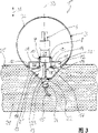
Fig. 1 is the diagrammatic side view that is fixed on the lighting device on the brick wall among first embodiment;
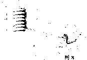
Fig. 2 is the diagrammatic side view of the lighting device among second embodiment that is placed in the soil;
Fig. 3 is the diagrammatic side view that is placed on the lighting device among the 3rd embodiment in the liquid as floating lamp;
Fig. 4 is the side sectional view according to the lamp socket of Fig. 1;
Fig. 5 is the side sectional view of the lighting device similar to the embodiment of Fig. 2;
Fig. 6 is the partial top view along the VI-VI section of Fig. 5;
Fig. 7 is the side sectional view according to the lamp socket of Fig. 3;
Fig. 8 is the signal detail drawing according to the lighting device of Fig. 1;
Fig. 9 is the schematic diagram according to the lighting device of Fig. 2;
Figure 10 a~10k is respectively side view and the vertical view of the various versions of lampshade in its installment state.
In the embodiment shown, for fear of being repeated in this description, the structural configuration that the structure division that function is identical is identical with function is represented with same label.
Have one smooth to make the light source 4 that columniform lamp socket 2, a globe holder 3 and form as electricity-saving lamp according to the lighting device 1 of Fig. 1.Lamp socket 2 is placed and is fixed on the conduct of being built up by brick and installs on the surface 5 ' of basic wall 5.For fixing, adopted a plurality of trip bolts 6 with the chain-dotted line representative, in Fig. 1, only show two trip bolts 6.Each trip bolt 6 pass lamp socket 2 radially outer district the through hole that matches with it 7 (see figure 4)s and be fixed in the brick wall 5.The surface 5 ' of wall also can with the mode of not describing in detail and horizontal plane acutangulates or the right angle.As for basis 5 is installed, it also can for example be the wall of vertical building.Lampshade 3 and lamp socket 2 are to form symmetrically with respect to the axis of symmetry 33 or the rotation of middle longitudinal axis that are parallel to axial 31 substantially.Lampshade 3 31 is placed in the lamp socket 2 then by the circumferential rotation of lampshade 3 along perpendicular to axial direction 31 and is screwed in lamp socket 2 vertically.To this, a lamp socket top 8 is set in the mesozone of lamp socket 2.With respect to the lamp socket top 8 of heart setting in the axis of symmetry 33 one cylindrical cross section is arranged and on its cylinder blanket, have one its be shaped as externally threaded lamp socket screw thread 9.Lamp socket screw thread 9 is shaped as lampshade screw thread 10 actings in conjunction of complementation of the lampshade 3 of internal thread with it, so that lampshade 3 can be screwed in the latter on being put into lamp socket 2 time.Lampshade screw thread 10 is equally with respect to heart setting in the axis of symmetry 33.Longitudinally axis is connected with the lid lampshade wall 32 that plays a part of lampshade 3 by a circumferential connection web 11 by ring seal along lamp socket 2 towards the screw thread tail end of the lampshade screw thread 10 of lamp socket 2.A plurality of check rod shapes also can be set connect web, to replace this connection web 11.
In the radially outer district that connects web 11 with tie point between the lampshade wall 32 or transition region form one along lamp socket 2 circumferentially to press version ring seal, its cross section almost be the lampshade flange 12 (referring to for example Fig. 5) of wedge shape.When lampshade 3 was installed, its lampshade flange 12 almost was that to admit lamp socket 2 be being positioned at the zone on the wall surface 5 ' and it being surrounded fully or encase of lamp socket 2 on form fit ground, until have only very little mobile space between lampshade flange 12 and wall surface 5 '.When tightening lampshade 3, the cylindrical surface of lampshade flange 12 and lamp socket 2 plays booster action fixing and guiding in easy to install considering.
In another version, lampshade flange 12 and opening border 26 will so constitute, and promptly support web 27 and link to each other with lampshade wall 32 by a web, and this web is roughly parallel to the installation surface that the basis is installed in the trend of installment state.This can for example represent by playing a part among lampshade 3 and Figure 10 a~10k that basic soil 16 is installed.
In the embodiment shown, the supporting web 27 that links to each other with lampshade wall 32 in the zone on opening border 26 is always towards the inner space of lampshade 3.
At first is the higher axial arrangement that is lamp socket 2 ' at Fig. 2 with at the lighting device shown in Fig. 51 ' with difference according to the lighting device 1 of Fig. 1.Compare with lamp socket 2, be used in a soft mounting foundation for example as the soil 16 anti-placement lighting devices 1 ' that the basis is installed with tumbling according to the higher structure height of the lamp socket 2 ' of Fig. 2 and Fig. 5 according to Fig. 1.In Fig. 2, lamp socket 2 ' is embedded in by installing in the following soil 16 of soil surface that the surface limits 16 '.The trip bolt 6 (Fig. 1) that has replaced being used for tightening lamp socket 2 at the soil 16 of installment state encirclement lamp socket 2 ' on solid installation basis 5.
In lighting device 1,1 ' installment state, lampshade 3 so covers lamp socket 2 or 2 ', so that in fact the latter can not be seen.At this moment, lampshade flange 12 is tangent with installation surface 5 ' or 16 ' towards the surface region that basis 5 or 16 is installed with it.
In embodiment according to Fig. 3 and Fig. 7, lighting device 1 " make as floating lamp.Though lamp socket 2 " structure be truncated cone shape and under water or the use that is used for other liquid 21 make, adopting herein has been favourable at lighting device 1 or the 1 ' lampshade 3 that uses.Lamp socket 2 " lamp socket border 19 with regard to its diameter, match with respective diameters according to the lamp socket 2 of Fig. 1 and Fig. 2,2 ' lamp socket border 19 so that this lampshade 3 can be used for all described lamp sockets 2,2 ', 2 " version.Lamp socket 2 " taper cause illuminating lamp 1 owing to its configuration with 3 pairs of centers of lampshade " whole be a pyriform or water droplet shape.An anti-especially location of tumbling can obtained thus below the liquid surface 21 ' that the surface is installed.When lamp socket border 19 and lampshade border 12 be positioned in an embodiment liquid surface 21 ' below the time, it is outstanding that liquid surface 21 ' is crossed on lamp socket top 8.When placing upper lamp shade 3, be positioned at thus as the lamp socket district of liquid 21 outsides that the basis is installed and light source 4 and all be covered and cannot see.
Be combined with a connection electric wire 13 that is used for light source 4 of cutting out in advance integratedly on lamp socket top 8.Connecting electric wire 13 is electrically connected with contact shoe 29.Light source 4 is placed in the contact shoe 29 and tightens, and thus be connected electric wire 13 and electrically contact.Contact shoe 29 is mechanically fixed and is crossed lamp socket top along the direction of lampshade 3 and give prominence in the center on lamp socket top 8.By electrical connections 14 for example binding post (Luesterklemme) or other suitable contact device, connect electric wire 13 and be connected with the power line 15 of outside, this power line 15 is connected to lamp socket 2,2 ', 2 with its link " on.To connect electric wire 13 and/or pre-prepd electric wire 15 can be introduced joint well in order making, on lamp socket top 8 and/or lamp socket 2,2 ', to be installed with an entrance hole 17 or a plurality of entrance hole 17.When laying the cable of lighting device, move uncontrollably for fear of cable, connecting electric wire 13 and/or pre-prepd electric wire 15 can penetrate by these entrance holes 17.
In Fig. 4, Fig. 5, Fig. 8 and Fig. 9, for drawing for purpose of brevity, not shown contact shoe 29.As another kind of scheme, also can be at lamp socket 2,2 ', 2 " go up the fixing unshowned suitable structural detail that electrically contacts with light source 4 of being used for herein.
Power supply electric wire 15 can be connected by its outer link and line voltage or low-voltage voltage source such as 12V battery.
Electrical connections and a part of lead 13,15 are arranged in lamp socket 2,2 ', 2 " annular receiving channel 25.This receiving channel 25 is limited by lamp socket top 8, connection web 11 and lamp socket border 19 substantially and thus there is good sealing the outside.Can obtain the cross section of different receiving channel 25 by different connection webs 11.In Fig. 1 to Fig. 3 and Figure 10 a~10k, with the cross section that connects web 11 just perpendicular to lampshade circumferentially make step or stairstepping, then make linear in contrast at Fig. 5, Fig. 8 and Fig. 9.
Fig. 7 shows the truncated cone shape lamp socket 2 according to Fig. 3 " side sectional view.Lamp socket 2 " along the relative leading-in end 22 of Y a threaded attachment 23 that is shaped is arranged with lamp socket border 19 at it thereon, it has the outer surface as spanner surface 28 that is used for fixing open-end wrench.Be screwed in threaded connector 24 (see figure 3)s compression in the internal thread 30 of threaded attachment 23 and be arranged on seal in threaded attachment 23 districts, that obviously do not illustrate and being threaded and being advantageously used in the tension force that alleviates the electric wire 15 of powering simultaneously herein as waterproof.
According to Fig. 7, lamp socket 2 " to cross lamp socket border 19 equally outstanding on lamp socket top 8.
Other version with lighting device is the same, and the receiving channel 25 that forms between lamp socket border 19 and lamp socket top 8 is used for admitting and clamping electrical connections 14 and electric wire 13,15.
Advantageously with a kind of lampshade 3 with different, be suitable for the lamp socket 2,2 ', 2 of special assembling condition separately " combinatory possibility.In this way, entire lighting device 1,1 ' and its different installation requirement that is adapted to can be economical, this is because it can obtain higher preprocessing degree.Also have, the storage of spare part also obtains simplifying.For lampshade 3 and different lamp sockets 2,2 ', 2 " combination importantly, lamp socket top 8 with under certain situation, make in the lamp socket district that installment state is covered by lampshade 3 structure identical or the same.Therefore, when remaining lamp socket district of configuration, in following special construction situation that needs to consider installation basis separately of the simple situation of manufacturing technology.
In another kind of version, in order to make lighting device 1,1 ' operational reliability is preferably arranged, it be shielded, prevent that moisture from entering (Fig. 8,9).To this, lighting device 1,1 ' installment state between lampshade flange 12 and lamp socket 2,2 ', imbed one along lamp socket 2,2 ' circumferentially for annular, its cross section is roughly potted component 18 semicircular, that do camber, that make of plastics, rubber or its analog.At this moment, potted component 18 shapes are placed on the lamp socket border 19 suitably.Because the specific formation of potted component 18, according to the lampshade 3 of Fig. 8 and Fig. 9 have a circular arc, at the lampshade groove 20 of supporting web 27 places depression, it is used for, and shape is admitted suitably and compression seal element 18.Seal the lighting device 1 that also can be used on as floating lamp use with the potted component that is arranged between lamp socket border 19 and the lampshade flange 12 self-evidently " in.
As can be used for dissimilar lamp socket 2,2 ', 2 with a kind of lampshade 3 ", also can with dissimilar be that the lampshade 3 of different structure form is used for a kind of lamp socket.At this moment, for different lampshade 3, as long as will make identical with the size of lampshade screw thread 10 with zone, particularly lampshade flange 12 that lamp socket matches.This can illustrate by Figure 10 a~10k, at this moment, as lamp socket, only exemplarily shows the lamp socket 2 ' that is placed in the soil 16.Rotational symmetric lampshade 3 is shown in Figure 10 a (taper), Figure 10 c (sphere), Figure 10 d (eggshell shape), Figure 10 e (cylindrical) and the figure i (truncated cone shape).Its cross section is polygonal lampshade 3 at 10b and Figure 10 k (being respectively square), shown in Figure 10 g (triangle) and Figure 10 h (octagonal).Figure 10 f illustrates a pyramid shape lampshade 3, and Figure 10 j illustrates a pyramid lampshade 3.
Claims (14)
1. a lighting device (1,1 ', 1 "); described lighting device comprises: one can go up the lamp socket placed (2,2 ', 2 ") in that basis (5,16,21) is installed, and lamp socket has an outer lamp socket border (19) and has one to be used for fixing on the lamp socket top (8) of installment state from the light source (4) basis (5,16,21) is installed gives prominence in the mesozone; Removably fixing lampshade (3) on lamp socket (2,2 ', 2 "); described lampshade covers light source (4) and from outstanding lamp socket district, basis (5,16,21) is installed; make and can only see lampshade (3) in installment state; it is characterized in that; described lampshade (3) has a lampshade flange (12) that forms a lampshade opening (26), and described lampshade flange (12) is provided with supporting web (27) the encirclement described lamp socket border (19) towards the inner space of lampshade (3).
2. device as claimed in claim 1 is characterized by, and the lamp socket top (8) of lamp socket (2,2 ', 2 ") has one as externally threaded lamp socket screw thread (9), and it is used to be used as the lampshade screw thread (10) of the complementation of internal thread lampshade (3) is tightened.
3. device as claimed in claim 2 is characterized by, and lampshade screw thread (10) is connected with lampshade flange (12) by the circumferential connection web (11) of its trend perpendicular to lampshade (3).
4. device as claimed in claim 3 is characterized by, and connects web (11) and self seals along the circumferential of lampshade (3).
5. as each device in the claim 1 to 4, it is characterized by, lampshade flange (12) surrounds lamp socket border (19) under situation of placing a potted component (18) placed in the middle.
6. as each device in the claim 1 to 4, it is characterized by, lampshade (3) is set as whole.
7. as each device in the claim 1 to 4, it is characterized by, it is rotational symmetric that lampshade (3) and lamp socket (2,2 ', 2 ") are set as.
8. as each device in the claim 1 to 4, it is characterized by, lampshade (3) is set as in its direction that basis (5,16,21) side is installed dorsad and becomes taper to dwindle shape.
9. as each device in the claim 1 to 4, it is characterized by, lamp socket (2 ") is done tapered or truncated cone shape, and described lamp socket (2 ") has the cross section that dwindles in the side towards lampshade (3) longitudinally.
10. as each device in the claim 1 to 4, it is characterized by, lamp socket (2 ', 2 ") can be placed at least in part in installment state and install in the basis (16,21).
11., it is characterized by as each device in the claim 1 to 4, on lamp socket (2,2 ', 2 "), electric light source (4) is set, at this moment, light source (4) can with go up fixing contact shoe (29) at lamp socket (2,2 ', 2 ") and electrically contact.
12. as each device in the claim 1 to 4, it is characterized by, contact shoe (29) be fixed on that lamp socket top (8) is gone up and with lamp socket screw thread (9) centering of being arranged to and on the surface of lamp socket top (8), forming.
13. as each device in the claim 1 to 4, it is characterized by, lamp socket (2,2 ', 2 ") have at least one be used for admitting be connected with light source (4) or with contact shoe (29) also can with the receiving channel (25) of energy supply source wire connecting (13,15).
14. the device as claim 13 is characterized by, receiving channel (25) is located at and connects between web (11) and the lamp socket (2,2 ', 2 ").
Applications Claiming Priority (4)
| Application Number | Priority Date | Filing Date | Title |
|---|---|---|---|
| DE29611401.4 | 1996-07-01 | ||
| DE29611401 | 1996-07-01 | ||
| DE29616020.2 | 1996-09-16 | ||
| DE29616020 | 1996-09-16 |
Publications (2)
| Publication Number | Publication Date |
|---|---|
| CN1222962A CN1222962A (en) | 1999-07-14 |
| CN1101915C true CN1101915C (en) | 2003-02-19 |
Family
ID=26059133
Family Applications (1)
| Application Number | Title | Priority Date | Filing Date |
|---|---|---|---|
| CN97195730A Expired - Fee Related CN1101915C (en) | 1996-07-01 | 1997-07-01 | Lighting device |
Country Status (13)
| Country | Link |
|---|---|
| US (1) | US6224241B1 (en) |
| EP (1) | EP0907865B1 (en) |
| JP (1) | JP4318319B2 (en) |
| CN (1) | CN1101915C (en) |
| AT (1) | ATE187812T1 (en) |
| AU (1) | AU3440097A (en) |
| BR (1) | BR9710020A (en) |
| CZ (1) | CZ290665B6 (en) |
| DE (2) | DE59700859D1 (en) |
| ES (1) | ES2142688T3 (en) |
| PL (1) | PL184559B1 (en) |
| PT (1) | PT907865E (en) |
| WO (1) | WO1998000671A1 (en) |
Families Citing this family (13)
| Publication number | Priority date | Publication date | Assignee | Title |
|---|---|---|---|---|
| DE19817616A1 (en) * | 1998-04-21 | 1999-11-04 | Rombach Beleuchtungstechnik Gm | Light fitting with bulb holder for bulb and shade forming light outlet opening and partly screening bulb |
| DE10058268A1 (en) * | 2000-11-23 | 2002-06-06 | Willi Wolfgang Oswald | floating light |
| TW498961U (en) * | 2001-04-17 | 2002-08-11 | Yu-Peng Liou | Structure improvement of lamp holder for decorative light |
| ITRN20020019A1 (en) * | 2002-04-12 | 2002-07-11 | Interlightning Agency Di Zanot | DECORATIVE GLASS FOR LAMPS |
| BE1015538A6 (en) * | 2003-05-23 | 2005-06-07 | Massive Nv | Wall light fixture. |
| JP5348826B2 (en) * | 2005-02-17 | 2013-11-20 | インベンテイオ・アクテイエンゲゼルシヤフト | Lens device for integration into a wall, coupling housing and device integrated with a wall with lens device, method of installing the device, and transport equipment having the device |
| US7325939B2 (en) * | 2005-10-14 | 2008-02-05 | Kenall Manufacturing Co. | Lighting for detention facility |
| US7410269B2 (en) * | 2006-06-06 | 2008-08-12 | S.C. Johnson & Son, Inc. | Decorative light system |
| US7458698B2 (en) * | 2006-06-15 | 2008-12-02 | S.C. Johnson & Son, Inc. | Decorative light system |
| CN101329471B (en) * | 2007-06-22 | 2010-09-29 | 群康科技(深圳)有限公司 | Backlight module unit, lamp tube clamping device and LCD device |
| US20110200956A1 (en) * | 2008-03-27 | 2011-08-18 | Franklin Damon L | Candle Holder |
| CN107401705A (en) * | 2017-09-10 | 2017-11-28 | 唐山市城市市政园林绿化工程有限公司 | Light fixture with Landscape Lighting and road lighting function |
| CN109442320A (en) * | 2018-10-24 | 2019-03-08 | 姜贵安 | A kind of cultivation navigation light |
Family Cites Families (15)
| Publication number | Priority date | Publication date | Assignee | Title |
|---|---|---|---|---|
| FR956714A (en) * | 1950-02-06 | |||
| DE961012C (en) | 1953-12-15 | 1957-03-28 | Peill & Putzler Gmbh | Ceiling light |
| GB815424A (en) | 1956-10-04 | 1959-06-24 | Jules Marius Hippolyte Mattico | A new or improved device for removably securing the globe of a lighting apparatus ona support |
| DE1157703B (en) | 1961-09-26 | 1963-11-21 | August Hetzel | Overbell attachment for preferably closed at the bottom of electrical ceiling lights |
| US3376413A (en) * | 1966-05-13 | 1968-04-02 | E F L Inc | Memorial light |
| US3370165A (en) * | 1966-12-28 | 1968-02-20 | Lightolier Inc | Recessed lighting fixture |
| JPS5426085A (en) * | 1977-07-29 | 1979-02-27 | Matsushita Electric Works Ltd | Method of watertightly sealing back surface of illuminator body |
| JPS56146301U (en) * | 1980-04-01 | 1981-11-04 | ||
| US4398237A (en) * | 1982-01-21 | 1983-08-09 | Doyel John S | Miniature battery-operated light |
| DE8911879U1 (en) | 1989-10-05 | 1990-01-04 | Bega Gantenbrink-Leuchten Ohg, 5750 Menden, De | |
| US5034869A (en) * | 1989-11-28 | 1991-07-23 | Choi Young J | Device for fixing a ceiling lamp to a ceiling |
| GB2246425A (en) | 1990-04-18 | 1992-01-29 | Philip Bryan Anthony Dawes | Electric pyramid lamp |
| DE9204941U1 (en) | 1992-04-09 | 1992-07-16 | Assche, Victor-Maria Van, 4350 Recklinghausen, De | |
| DE9304052U1 (en) | 1993-03-19 | 1993-08-19 | Narva Gluehlampenwerk Oberweis | Jewelry hangers |
| US5567041A (en) * | 1995-08-14 | 1996-10-22 | Slocum; Karl | Self supporting recessed ceiling fixture |
-
1997
- 1997-01-07 US US09/214,315 patent/US6224241B1/en not_active Expired - Fee Related
- 1997-07-01 JP JP50384198A patent/JP4318319B2/en not_active Expired - Fee Related
- 1997-07-01 ES ES97930455T patent/ES2142688T3/en not_active Expired - Lifetime
- 1997-07-01 AU AU34400/97A patent/AU3440097A/en not_active Abandoned
- 1997-07-01 CZ CZ19984387A patent/CZ290665B6/en not_active IP Right Cessation
- 1997-07-01 WO PCT/EP1997/003414 patent/WO1998000671A1/en active IP Right Grant
- 1997-07-01 PT PT97930455T patent/PT907865E/en unknown
- 1997-07-01 DE DE59700859T patent/DE59700859D1/en not_active Expired - Lifetime
- 1997-07-01 CN CN97195730A patent/CN1101915C/en not_active Expired - Fee Related
- 1997-07-01 AT AT97930455T patent/ATE187812T1/en not_active IP Right Cessation
- 1997-07-01 PL PL97330929A patent/PL184559B1/en not_active IP Right Cessation
- 1997-07-01 BR BR9710020-0A patent/BR9710020A/en not_active IP Right Cessation
- 1997-07-01 DE DE29723340U patent/DE29723340U1/en not_active Expired - Lifetime
- 1997-07-01 EP EP97930455A patent/EP0907865B1/en not_active Expired - Lifetime
Also Published As
| Publication number | Publication date |
|---|---|
| JP2000514233A (en) | 2000-10-24 |
| BR9710020A (en) | 2000-01-25 |
| PL330929A1 (en) | 1999-06-07 |
| PL184559B1 (en) | 2002-11-29 |
| EP0907865B1 (en) | 1999-12-15 |
| CZ438798A3 (en) | 2000-04-12 |
| CZ290665B6 (en) | 2002-09-11 |
| ES2142688T3 (en) | 2000-04-16 |
| DE29723340U1 (en) | 1998-07-30 |
| PT907865E (en) | 2000-06-30 |
| DE59700859D1 (en) | 2000-01-20 |
| JP4318319B2 (en) | 2009-08-19 |
| WO1998000671A1 (en) | 1998-01-08 |
| US6224241B1 (en) | 2001-05-01 |
| EP0907865A1 (en) | 1999-04-14 |
| ATE187812T1 (en) | 2000-01-15 |
| AU3440097A (en) | 1998-01-21 |
| CN1222962A (en) | 1999-07-14 |
Similar Documents
| Publication | Publication Date | Title |
|---|---|---|
| CN1101915C (en) | Lighting device | |
| CN106051477B (en) | The improvement of modular lighting device assembly or relative improvement | |
| US7347706B1 (en) | Light emitting diode (LED) based street light and other lighting applications | |
| US10982827B2 (en) | Modular assembled outdoor lighting device and installation method thereof, light pole structure | |
| KR100961258B1 (en) | Light combinated with cable | |
| US20230080092A1 (en) | Luminaire | |
| KR101044799B1 (en) | Scenery lighting lamp for underground reclamation | |
| KR101726862B1 (en) | A lighting device for controlling a car lane | |
| JP4632054B2 (en) | lighting equipment | |
| US20170234024A1 (en) | A Support Structure | |
| US20160109101A1 (en) | Lighting Fixture Mounting Post | |
| KR100754900B1 (en) | Streetlight | |
| CN2795651Y (en) | Water-proof lamp | |
| KR200412313Y1 (en) | Roof burying type lighting lamp socket | |
| WO2011062367A2 (en) | Scenic light and management system for scenic lights | |
| CN102748621B (en) | Polygonal splicing type LED (Light-Emitting Diode) lamp | |
| GB2436026A (en) | A cover for a lamp | |
| CN215112304U (en) | Induction type illuminating lamp | |
| KR200418692Y1 (en) | streetlight | |
| US11668443B2 (en) | Luminaire uplight device and related methods | |
| KR102092342B1 (en) | Lamp socket housing and lamp assembly device thereof | |
| CN210822677U (en) | Conveniently maintain type beacon | |
| CN208398001U (en) | It is a kind of for constructing the lamp holder of combined type outside light | |
| KR100779232B1 (en) | Column type streetlight | |
| CN205824788U (en) | LED is independently arranged the ceiling lamp light source plate of lens |
Legal Events
| Date | Code | Title | Description |
|---|---|---|---|
| C06 | Publication | ||
| PB01 | Publication | ||
| C10 | Entry into substantive examination | ||
| SE01 | Entry into force of request for substantive examination | ||
| C14 | Grant of patent or utility model | ||
| GR01 | Patent grant | ||
| C17 | Cessation of patent right | ||
| CF01 | Termination of patent right due to non-payment of annual fee |
Granted publication date: 20030219 Termination date: 20120701 |