CN110184792B - Washing machine and control method thereof - Google Patents
Washing machine and control method thereof Download PDFInfo
- Publication number
- CN110184792B CN110184792B CN201910133059.0A CN201910133059A CN110184792B CN 110184792 B CN110184792 B CN 110184792B CN 201910133059 A CN201910133059 A CN 201910133059A CN 110184792 B CN110184792 B CN 110184792B
- Authority
- CN
- China
- Prior art keywords
- drum
- temperature sensor
- temperature
- induction heater
- tub
- Prior art date
- Legal status (The legal status is an assumption and is not a legal conclusion. Google has not performed a legal analysis and makes no representation as to the accuracy of the status listed.)
- Active
Links
Images


Classifications
-
- D—TEXTILES; PAPER
- D06—TREATMENT OF TEXTILES OR THE LIKE; LAUNDERING; FLEXIBLE MATERIALS NOT OTHERWISE PROVIDED FOR
- D06F—LAUNDERING, DRYING, IRONING, PRESSING OR FOLDING TEXTILE ARTICLES
- D06F34/00—Details of control systems for washing machines, washer-dryers or laundry dryers
- D06F34/14—Arrangements for detecting or measuring specific parameters
- D06F34/26—Condition of the drying air, e.g. air humidity or temperature
-
- D—TEXTILES; PAPER
- D06—TREATMENT OF TEXTILES OR THE LIKE; LAUNDERING; FLEXIBLE MATERIALS NOT OTHERWISE PROVIDED FOR
- D06F—LAUNDERING, DRYING, IRONING, PRESSING OR FOLDING TEXTILE ARTICLES
- D06F33/00—Control of operations performed in washing machines or washer-dryers
- D06F33/30—Control of washing machines characterised by the purpose or target of the control
-
- D—TEXTILES; PAPER
- D06—TREATMENT OF TEXTILES OR THE LIKE; LAUNDERING; FLEXIBLE MATERIALS NOT OTHERWISE PROVIDED FOR
- D06F—LAUNDERING, DRYING, IRONING, PRESSING OR FOLDING TEXTILE ARTICLES
- D06F21/00—Washing machines with receptacles, e.g. perforated, having a rotary movement, e.g. oscillatory movement
- D06F21/02—Washing machines with receptacles, e.g. perforated, having a rotary movement, e.g. oscillatory movement about a horizontal axis
- D06F21/04—Washing machines with receptacles, e.g. perforated, having a rotary movement, e.g. oscillatory movement about a horizontal axis within an enclosing receptacle
-
- D—TEXTILES; PAPER
- D06—TREATMENT OF TEXTILES OR THE LIKE; LAUNDERING; FLEXIBLE MATERIALS NOT OTHERWISE PROVIDED FOR
- D06F—LAUNDERING, DRYING, IRONING, PRESSING OR FOLDING TEXTILE ARTICLES
- D06F34/00—Details of control systems for washing machines, washer-dryers or laundry dryers
- D06F34/14—Arrangements for detecting or measuring specific parameters
-
- D—TEXTILES; PAPER
- D06—TREATMENT OF TEXTILES OR THE LIKE; LAUNDERING; FLEXIBLE MATERIALS NOT OTHERWISE PROVIDED FOR
- D06F—LAUNDERING, DRYING, IRONING, PRESSING OR FOLDING TEXTILE ARTICLES
- D06F37/00—Details specific to washing machines covered by groups D06F21/00 - D06F25/00
- D06F37/02—Rotary receptacles, e.g. drums
- D06F37/04—Rotary receptacles, e.g. drums adapted for rotation or oscillation about a horizontal or inclined axis
-
- D—TEXTILES; PAPER
- D06—TREATMENT OF TEXTILES OR THE LIKE; LAUNDERING; FLEXIBLE MATERIALS NOT OTHERWISE PROVIDED FOR
- D06F—LAUNDERING, DRYING, IRONING, PRESSING OR FOLDING TEXTILE ARTICLES
- D06F39/00—Details of washing machines not specific to a single type of machines covered by groups D06F9/00 - D06F27/00
- D06F39/04—Heating arrangements
-
- D—TEXTILES; PAPER
- D06—TREATMENT OF TEXTILES OR THE LIKE; LAUNDERING; FLEXIBLE MATERIALS NOT OTHERWISE PROVIDED FOR
- D06F—LAUNDERING, DRYING, IRONING, PRESSING OR FOLDING TEXTILE ARTICLES
- D06F58/00—Domestic laundry dryers
- D06F58/20—General details of domestic laundry dryers
- D06F58/26—Heating arrangements, e.g. gas heating equipment
-
- D—TEXTILES; PAPER
- D06—TREATMENT OF TEXTILES OR THE LIKE; LAUNDERING; FLEXIBLE MATERIALS NOT OTHERWISE PROVIDED FOR
- D06F—LAUNDERING, DRYING, IRONING, PRESSING OR FOLDING TEXTILE ARTICLES
- D06F58/00—Domestic laundry dryers
- D06F58/32—Control of operations performed in domestic laundry dryers
- D06F58/34—Control of operations performed in domestic laundry dryers characterised by the purpose or target of the control
- D06F58/36—Control of operational steps, e.g. for optimisation or improvement of operational steps depending on the condition of the laundry
- D06F58/38—Control of operational steps, e.g. for optimisation or improvement of operational steps depending on the condition of the laundry of drying, e.g. to achieve the target humidity
- D06F58/40—Control of the initial heating of the drying chamber to its operating temperature
-
- D—TEXTILES; PAPER
- D06—TREATMENT OF TEXTILES OR THE LIKE; LAUNDERING; FLEXIBLE MATERIALS NOT OTHERWISE PROVIDED FOR
- D06F—LAUNDERING, DRYING, IRONING, PRESSING OR FOLDING TEXTILE ARTICLES
- D06F58/00—Domestic laundry dryers
- D06F58/32—Control of operations performed in domestic laundry dryers
- D06F58/34—Control of operations performed in domestic laundry dryers characterised by the purpose or target of the control
- D06F58/50—Responding to irregular working conditions, e.g. malfunctioning of blowers
-
- D—TEXTILES; PAPER
- D06—TREATMENT OF TEXTILES OR THE LIKE; LAUNDERING; FLEXIBLE MATERIALS NOT OTHERWISE PROVIDED FOR
- D06F—LAUNDERING, DRYING, IRONING, PRESSING OR FOLDING TEXTILE ARTICLES
- D06F2103/00—Parameters monitored or detected for the control of domestic laundry washing machines, washer-dryers or laundry dryers
- D06F2103/28—Air properties
- D06F2103/32—Temperature
-
- D—TEXTILES; PAPER
- D06—TREATMENT OF TEXTILES OR THE LIKE; LAUNDERING; FLEXIBLE MATERIALS NOT OTHERWISE PROVIDED FOR
- D06F—LAUNDERING, DRYING, IRONING, PRESSING OR FOLDING TEXTILE ARTICLES
- D06F2103/00—Parameters monitored or detected for the control of domestic laundry washing machines, washer-dryers or laundry dryers
- D06F2103/52—Parameters monitored or detected for the control of domestic laundry washing machines, washer-dryers or laundry dryers related to electric heating means, e.g. temperature or voltage
-
- D—TEXTILES; PAPER
- D06—TREATMENT OF TEXTILES OR THE LIKE; LAUNDERING; FLEXIBLE MATERIALS NOT OTHERWISE PROVIDED FOR
- D06F—LAUNDERING, DRYING, IRONING, PRESSING OR FOLDING TEXTILE ARTICLES
- D06F2105/00—Systems or parameters controlled or affected by the control systems of washing machines, washer-dryers or laundry dryers
- D06F2105/02—Water supply
- D06F2105/04—Water supply from separate hot and cold water inlets
-
- D—TEXTILES; PAPER
- D06—TREATMENT OF TEXTILES OR THE LIKE; LAUNDERING; FLEXIBLE MATERIALS NOT OTHERWISE PROVIDED FOR
- D06F—LAUNDERING, DRYING, IRONING, PRESSING OR FOLDING TEXTILE ARTICLES
- D06F2105/00—Systems or parameters controlled or affected by the control systems of washing machines, washer-dryers or laundry dryers
- D06F2105/10—Temperature of washing liquids; Heating means therefor
-
- D—TEXTILES; PAPER
- D06—TREATMENT OF TEXTILES OR THE LIKE; LAUNDERING; FLEXIBLE MATERIALS NOT OTHERWISE PROVIDED FOR
- D06F—LAUNDERING, DRYING, IRONING, PRESSING OR FOLDING TEXTILE ARTICLES
- D06F2105/00—Systems or parameters controlled or affected by the control systems of washing machines, washer-dryers or laundry dryers
- D06F2105/16—Air properties
- D06F2105/20—Temperature
-
- D—TEXTILES; PAPER
- D06—TREATMENT OF TEXTILES OR THE LIKE; LAUNDERING; FLEXIBLE MATERIALS NOT OTHERWISE PROVIDED FOR
- D06F—LAUNDERING, DRYING, IRONING, PRESSING OR FOLDING TEXTILE ARTICLES
- D06F2105/00—Systems or parameters controlled or affected by the control systems of washing machines, washer-dryers or laundry dryers
- D06F2105/28—Electric heating
-
- D—TEXTILES; PAPER
- D06—TREATMENT OF TEXTILES OR THE LIKE; LAUNDERING; FLEXIBLE MATERIALS NOT OTHERWISE PROVIDED FOR
- D06F—LAUNDERING, DRYING, IRONING, PRESSING OR FOLDING TEXTILE ARTICLES
- D06F25/00—Washing machines with receptacles, e.g. perforated, having a rotary movement, e.g. oscillatory movement, the receptacle serving both for washing and for centrifugally separating water from the laundry and having further drying means, e.g. using hot air
-
- D—TEXTILES; PAPER
- D06—TREATMENT OF TEXTILES OR THE LIKE; LAUNDERING; FLEXIBLE MATERIALS NOT OTHERWISE PROVIDED FOR
- D06F—LAUNDERING, DRYING, IRONING, PRESSING OR FOLDING TEXTILE ARTICLES
- D06F37/00—Details specific to washing machines covered by groups D06F21/00 - D06F25/00
- D06F37/42—Safety arrangements, e.g. for stopping rotation of the receptacle upon opening of the casing door
-
- D—TEXTILES; PAPER
- D06—TREATMENT OF TEXTILES OR THE LIKE; LAUNDERING; FLEXIBLE MATERIALS NOT OTHERWISE PROVIDED FOR
- D06F—LAUNDERING, DRYING, IRONING, PRESSING OR FOLDING TEXTILE ARTICLES
- D06F39/00—Details of washing machines not specific to a single type of machines covered by groups D06F9/00 - D06F27/00
- D06F39/08—Liquid supply or discharge arrangements
- D06F39/088—Liquid supply arrangements
Abstract
The washing machine of the present invention comprises: an outer tub for holding water; a drum made of metal and rotating in the tub; an induction heater fixed to the tub in a state of being spaced apart from the drum, for heating the drum; a first temperature sensor provided with a metal pipe heated by the induction heater and a thermistor arranged in the pipe, at least a part of the pipe being exposed between the tub and the drum; a second temperature sensor disposed at a position farther than the first temperature sensor with respect to the induction heater in a circumferential direction, for detecting a temperature of air between the tub and the drum; and a control unit that controls the induction heater based on a first detection value of the first temperature sensor and a second detection value of the second temperature sensor.
Description
Technical Field
The present invention relates to a washing machine provided with an induction heater and a control method thereof.
Background
In general, a washing machine is configured such that a drum for receiving laundry is rotatably provided within an outer tub for providing a space for storing water. The drum is formed with a through hole, whereby water in the tub flows into the drum, and the laundry is moved by the rotation of the drum while the contaminants of the laundry are removed.
Such a washing machine may also be provided with a heater for heating the water in the outer tub. In general, the heater is operated in a state in which water is stored in the tub, and directly heats water. However, this method requires the heater to be always operated in a state where water is stored for safety reasons, and although the heater may be used to heat water in the tub, it is not suitable to be used to heat air in the drum or to heat laundry in a wet state before dehydration in a state where water is not present in the tub.
As a washing machine adopting a method of directly heating a drum in contact with laundry, JP2004135998A discloses a washing and drying machine (or a washing machine having a drying function) provided with a non-contact heating device using microwaves, electromagnetic induction, infrared rays, or the like. The washing and drying machine includes a temperature sensor for measuring a temperature of the drum, and the temperature sensor is required to measure a temperature of the drum as a rotating body, and thus is configured to have a non-contact type structure capable of estimating the temperature without contacting the drum, but JP2004135998A does not specifically disclose a specific structure of the temperature sensor.
EP2400052a1 discloses a washing machine in which a drum is heated by an induction heating system (induction heating system). The washing machine is provided with a heat sensor between the drum and a water tank (or an outer tub) and is configured to be able to detect a temperature of water or air in the water tank. The above-described manner can estimate the temperature of the drum only based on the temperature of water or air. However, although the drum is sensitive to temperature change according to the output of the induction heating system, the temperature of the water or air changes slowly, and thus the value detected by the heat sensor may not accurately reflect the temperature change of the drum.
Disclosure of Invention
The problems to be solved by the present invention are as follows:
first, in a washing machine provided with an induction heater for heating a drum, the temperature of the drum is accurately estimated without contacting the drum.
Second, a washing machine and a control method thereof are provided to achieve detection of such drum temperature by using a thermistor, without using expensive equipment such as an infrared ray sensor.
Third, a washing machine and a control method thereof are provided, which estimate the temperature of the drum based on the detected values of two temperature sensors for detecting the temperature of air between the drum and the tub, and any one of the two temperature sensors is provided to be heated by the induction heater, and can accurately estimate the temperature of the drum in consideration of the amount of heat transferred to the entire system due to such heating.
The washing machine of the present invention comprises: a metal roller arranged in the outer barrel; and an induction heater heating the drum in a state of being spaced apart from the drum. A first temperature sensor and a second temperature sensor for detecting a temperature of the drum are provided.
The first temperature sensor and the second temperature sensor are used for detecting the temperature of the air between the drum and the tub. The first temperature sensor is heated and generates heat by the induction heater, and the second temperature sensor detects temperature at a position spaced further apart from the induction heater in a circumferential direction than the first temperature sensor.
The drum temperature is estimated based on a first detection value of the first temperature sensor and a second detection value of the second temperature sensor, and the control unit controls the induction heater based on the estimated drum temperature.
A thermistor is disposed in a metal pipe of the first temperature sensor heated by the induction heater, and a temperature detected by the thermistor reflects a temperature rise of the pipe by the induction heater.
The pipe functions as a heating element that heats air between the drum and the tub, and affects a detection value of the second temperature sensor. Here, the second temperature sensor is preferably disposed outside an effective heating range of the induction heater.
The temperature equation for determining the drum temperature can be established from the relationship among the amount of heat generated by the induction heater, the amount of heat generated by the first temperature sensor, and the amount of heat generated by the drum by determining the detection value of the first temperature sensor and the detection value of the second temperature sensor. The temperature equation has a detection value of the first temperature sensor as a variable, and since the detection value of the first temperature sensor varies with the output of the induction heater, the temperature of the drum is a value sensitively varying with the output of the induction heater.
A washing machine according to an aspect of the present invention includes: an outer tub for storing water; a drum made of metal and rotating in the tub; an induction heater fixed to the tub in a state of being spaced apart from the drum, for heating the drum; a first temperature sensor provided with a metal pipe heated by the induction heater and a thermistor arranged in the pipe, at least a part of the pipe being exposed between the tub and the drum; a second temperature sensor disposed at a position spaced apart from the induction heater in a circumferential direction farther than the first temperature sensor, for detecting a temperature of air between the tub and the drum; and a control unit that controls the induction heater based on a first detection value of the first temperature sensor and a second detection value of the second temperature sensor.
The control part may calculate the temperature of the drum based on a linear combination of the first detection value and the second detection value, and control the induction heater so that the temperature of the drum is within a predetermined range. The control unit may calculate the temperature of the drum by compensating the second detection value based on a difference between the first detection value and the second detection value.
The second temperature sensor may be disposed at a position of 55 to 65 degrees from the first temperature sensor with respect to the center of the drum.
The second detection value may have a phase less than the first detection value.
A cooling water port for supplying cooling water for condensing moisture in air in the tub may be provided at a side of the tub, and the first and second temperature sensors may be disposed at an upper side than the cooling water port.
The tube may be located in a region overlapping with the induction heater when the induction heater is viewed vertically from above.
A sensor installation port through which the pipe passes is formed at the outer tub, and the first temperature sensor may further include a soft sealing member for air-tightly sealing between the pipe and the sensor installation port. The sealing member is formed in a tubular shape extending in a length direction of the pipe, and the pipe may be disposed in a hollow formed inside the sealing member, and the first temperature sensor may further include a heat insulating cover for covering a portion of the pipe passing through an upper end of the sealing member and protruding to an outside of the outer tub.
A fixing groove may be formed at the sealing member for inserting the outer circumference of the sensor installation port to fix the sealing member in the sensor installation port.
A washing machine according to another aspect of the present invention includes: an outer tub for storing water; a drum made of metal and rotating in the tub; an induction heater fixed to the tub in a state of being spaced apart from the drum, for heating the drum; a first temperature sensor and a second temperature sensor each provided with a tube made of a metal material and a thermistor arranged in the tube; and a control unit configured to control the induction heater based on a detection value of the first temperature sensor and a detection value of the second temperature sensor, wherein at least a part of a pipe of the first temperature sensor is exposed between the tub and the drum, the first temperature sensor is disposed within an effective heating range in which a temperature of the pipe of the first temperature sensor is increased by a magnetic flux incident from the induction heater, and the second temperature sensor is disposed at a position spaced further from the induction heater in a circumferential direction than the first temperature sensor and outside the effective heating range.
The control method of the washing machine of the invention comprises the following steps: a step of operating the induction heater; and b, controlling the induction heater based on a first detection value of the first temperature sensor and a second detection value of the second temperature sensor.
The step b may include a step of finding the temperature of the drum based on a linear combination of the first detection value and the second detection value; and controlling the induction heater so that the temperature of the drum is within a preset range.
The step of finding the temperature may include a step of finding the temperature of the drum by compensating the second detection value based on a difference between the first detection value and the second detection value.
The second detection value may have a phase less than the first detection value.
The washing machine and the control method thereof of the present invention have the following effects:
first, in the washing machine provided with the induction heater for heating the drum, the temperature of the drum can be estimated more accurately than in the conventional method of estimating the temperature of the drum using one temperature sensor.
Secondly, the temperature of the drum is detected by a thermistor without using expensive equipment such as an infrared sensor, thereby reducing manufacturing costs.
Third, in the process of determining the temperature of the drum, the output (or input) of the induction heater is taken into consideration, thereby having an effect of sensitively detecting the temperature change of the drum according to the output change of the induction heater.
Drawings
Fig. 1 is a side sectional view of a washing machine according to an embodiment of the present invention.
Fig. 2 is an exploded perspective view of the outer tub and the induction heater.
Fig. 3 is a top view of the heater base shown in fig. 2.
Fig. 4 is a diagram schematically showing the positions where the first temperature sensor and the second temperature sensor are provided.
Fig. 5A is a view showing a state where the first temperature sensor is disposed in the outer tub, and fig. 5B is a view showing a section of the thermistor.
Fig. 6 is a graph showing temporal changes in the actual temperature Td _ p of the drum, the detected value T1 of the first temperature sensor, the detected value T2 of the second temperature sensor, and the estimated value Td of the drum temperature when the induction heater is controlled in the prescribed mode.
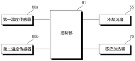
Fig. 7 is a block diagram illustrating a control relationship between main components of the washing machine according to an embodiment of the present invention.
Fig. 8 is a diagram for explaining a process of obtaining an estimated value of the drum temperature, and shows the amount of heat transferred among the induction heater, the drum, and the first temperature sensor.
Detailed Description
The advantages, features and methods of accomplishing the same will become more apparent from the following detailed description of the embodiments with reference to the accompanying drawings. However, the present invention is not limited to the embodiments disclosed below, and may be embodied in various forms different from each other, and the embodiments are provided only for the purpose of fully disclosing the present invention and fully disclosing the scope of the present invention to those skilled in the art, and the scope of the present invention is determined only by the scope of the claims. Like reference numerals denote like constituent elements throughout the specification.
Fig. 1 is a side sectional view of a washing machine according to an embodiment of the present invention. Fig. 2 is an exploded perspective view illustrating an outer tub and an induction heater. Fig. 3 is a top view of the heater base shown in fig. 2.
Referring to fig. 1 to 3, the housings 11, 12, 13, and 14 form an external appearance of the washing machine 1 according to the embodiment of the present invention, and an inlet for putting laundry is formed at a front side surface thereof. The housing 11, 12, 13, 14 may include: a housing 11, wherein the front side of the housing 11 is open and has a left side, a right side and a back side; and a front panel 12 coupled to the open front side of the cabinet 11 and having the inlet. In addition, the housing 11, 12, 13, 14 may further include: a top plate 13 for covering the open upper side of the cabinet 11; and a control panel 14 disposed on the upper side of the front panel 12.
An outer tub 40 for storing water is disposed in the housings 11, 12, 13, 14. An inlet is formed at a front side surface of the tub 40 to allow laundry to be input, and the inlet is communicated with an input port formed at the front panel 12 through a gasket 37.
The front panel 12 is provided with a door 15 for opening and closing the inlet, and the door 15 is rotatable. The control panel 14 is provided with: a display unit (not shown) for displaying various status information of the washing machine 1; and an input unit (not shown) for receiving various control commands such as a washing course, an operation time for each trip, and a reservation from a user.
A dispenser 34 for supplying additives such as laundry detergent, laundry softener, or bleach to the outer tub 40 is provided. The dispenser 34 includes: a detergent box for storing the additive; and a dispenser housing for accommodating the detergent box, the detergent box being accessible from and accessible from the dispenser housing. A water supply hose 27 for allowing raw water to flow therein by being connected to an external water source such as a water tap and a water supply valve 25 for restricting the water supply hose 27 may be provided. If the water supply valve 25 is opened and water is supplied through the water supply hose 27, the detergent in the detergent box is mixed with the water and flows into the outer tub 40.
The outer tub 40 may be hung on the top plate 13 by a spring 24 and supported by a damper 26 disposed at a lower side. Thus, the vibration of the outer tub 40 is buffered by the spring 24 and the damper 26.
The drum 22 is rotatably disposed in the tub 40. The drum 22 is made of a material (or a ferromagnetic material) which can induce a current by a material (or a magnetic field (or a magnetic force)) heated in a non-contact manner by an induction heater 70 (described later), preferably a metal material, for example, stainless steel (stainless steel), and a plurality of through holes 22h may be formed in the drum 22 so that water can be exchanged between the tub 40 and the drum 22.
The washing machine of the present embodiment is a front-loading washing machine in which the drum 22 rotates about a horizontal axis (axis, O). However, the present invention is not limited to this, and the present invention may be applied to a top loading type washing machine, and in this case, a drum that rotates about a vertical axis (axis) is provided.
The drum 22 is rotated by a driving unit 35, and a lifter 29 is provided inside to lift the laundry when rotating. The driving part 35 may include a motor capable of controlling a rotation direction and speed. The motor is preferably a Brushless Direct Current (BLDC) motor, but is not necessarily limited thereto.
Can be provided with: a drain bellows 51 for discharging water in the tub 40 to the outside; and a pump 59 for pumping the water discharged through the drain bellows 51 to the drain hose 53. The water pumped by the pump 59 is discharged to the outside of the washing machine through the drain hose 53.
An induction heater 70(induction heater) for heating the drum 22 is provided. The induction heater 70 is a heater using an induction current generated by a magnetic field as a heat source, and utilizes the following principle: eddy current (eddy current) is generated in a metal by an electromagnetic induction phenomenon when the metal is placed in a magnetic field, and the metal is heated by joule heat.
The induction heater 70 is fixed to the tub 40 in a state of being spaced apart from the drum 22. The drum 22, which is a metal material, is heated when the induction heater 70 is operated. The tub 40 is made of a material (preferably, synthetic resin) through which a magnetic field can pass, and the induction heater 70 is disposed outside the tub 40. However, the induction heater 70 is not limited thereto, and may be disposed inside the tub 40.
The induction heater 70 may include: a coil 71 for applying an electric current; a heater base 74 for fixing the coil 71; and a heater cover 72 combined with the heater base 74 at an upper side of the coil 71 and covering the coil 71.
The heater base 74 may be fixed to the outer tub 40. The heater base 74 may be disposed outside the outer tub 40, preferably on the upper side of the outer tub 40. A first coupling protrusion 743 is formed at the heater base 74, and the first coupling protrusion 743 is formed with a fastening hole. The four first coupling protrusions 743 may be configured to be symmetrical. A fastening protrusion 46 is formed at a position of the outer tub 40 corresponding to the first coupling protrusion 743. The heater base 74 is formed in a substantially flat shape, preferably a shape substantially corresponding to the curvature of the outer peripheral surface of the outer tub 40. The heater base 74 is made of a material through which a magnetic field can pass, and is preferably made of synthetic resin.
The coil 71 is fixed to the upper side of the heater base 74. In the embodiment, the coil 71 is formed in a shape in which one wire 71a is curled multiple times on the upper side of the heater base 74 with reference to the same center, and may be formed of a plurality of wires having a closed curve shape with the same center according to the embodiment.
A fixing rib 742 for fixing the coil 71 protrudes from an upper side 741 of the heater base 74. The fixing ribs 742 have a curled shape while maintaining a space 74a corresponding to the diameter of the wire 71a constituting the coil 71. The coil 71 may be constructed by winding the wire 71a along the space 74 a.
A strong magnet may be provided in the heater cover 72. The strong magnet may include ferrite (ferrite). The strong magnet may be fixed to the bottom surface of the heater cover 72. Since the high impedance of the ferrite prevents the generation of an eddy current (eddy current), a current is induced concentratedly at the drum 22 positioned at the lower side of the coil 71, whereby the drum 22 can be heated efficiently.
A cooling fan 55 for cooling the coil 71 may be provided at the heater cover 72. A fan attachment 72d is formed in the heater cover 72, and the fan attachment 72d constitutes a ventilation flow path through which air flows between a space for accommodating the coil 71 and the outside, and the cooling fan 55 is disposed in the ventilation flow path.
At a position of the heater cover 72 corresponding to the first coupling protrusion 743 of the heater base 74, a second coupling protrusion 72b is formed, and the second coupling protrusion 72b is formed with a fastening hole. The screw (not shown) may be fastened to the fastening boss 46 after passing through the second coupling protrusion 72b and the first coupling protrusion 743 in sequence.
On the other hand, in order to treat the laundry in the drum 22 at a desired temperature, it is necessary to be able to accurately control the temperature of the drum 22. Although the temperature of the drum 22 is greatly influenced by the output of the induction heater 70, it is also influenced by various factors such as the amount of laundry put into the drum 22, the amount of water stored in the tub 40, the rotation speed of the drum 22, and the amount of moisture contained in the laundry. Therefore, it is difficult to obtain an accurate value by estimating the temperature of the drum 22 only with the output (or input) of the induction heater 70.
Further, it is generally assumed that the washing, rinsing, dehydrating, drying, etc. strokes are performed on the basis of the rotating drum 22, so that it is difficult to measure the temperature of the rotating drum 22 using a contact temperature sensor.
Therefore, the present invention is provided with two temperature sensors 80a, 80b, and the temperature sensors 80a, 80b can measure the temperatures of the air at two locations between the drum 22 and the tub 40, and estimate the temperature of the drum 22 based on the values detected by the temperature sensors 80a, 80 b.
In this method, the temperature of the air is measured and the temperature of the drum 22 is estimated based on the result, so that the temperature of the drum 22 is not directly measured, but the values detected by the two temperature sensors 80a and 80b are used, so that not only the temperature of the drum 22 can be estimated more accurately, but also the temperature change of the drum 22 can be grasped more sensitively than the case of detecting with one temperature sensor in the past.
Fig. 4 is a diagram schematically showing the positions where the first temperature sensor and the second temperature sensor are provided. Fig. 5A is a view showing a state where the first temperature sensor is disposed in the outer tub, and fig. 5B is a view showing a section of the thermistor. Fig. 6 is a graph showing temporal changes in the actual temperature Td _ p of the drum, the detected value T1 of the first temperature sensor, the detected value T2 of the second temperature sensor, and the estimated value Td of the drum temperature when the induction heater is controlled in the prescribed mode. Fig. 7 is a block diagram illustrating a control relationship between main components of the washing machine according to an embodiment of the present invention. Fig. 8 is a diagram for explaining a process of obtaining an estimated value of the drum temperature, and shows an amount of heat transferred among the induction heater, the drum, and the first temperature sensor.
Referring to fig. 4 to 8, the two temperature sensors 80a, 80b include a first temperature sensor 80a and a second temperature sensor 80 b. The first temperature sensor 80a itself is heated by the induction heater 70, and the temperature detected by the first temperature sensor 80a is higher than the temperature Ta of the air inside the outer tub 40 under the normal operation condition of the washing machine. That is, the first temperature sensor 80a is a heating element for transferring heat to the air in the tub 40 in a state of being heated by the induction heater 70, and the amount of heat transferred to the air at this time is shown by Q1 in fig. 8.
Referring to fig. 5, the first temperature sensor 80a may include a thermistor assembly 81 and a heat insulating cover 83. The thermistor assembly 81 may include: a (preferably, metal) pipe 812 made of a material that can be heated by the induction heater 70; and a thermistor 813(thermistor) disposed in the tube 812. Here, at least a portion of the outer surface of the duct 812 is exposed between the tub 40 and the drum 22 for detecting the temperature of the air. Since the induction heater 70 causes an induction current to flow through the metal and the pipe 812 is heated, the temperature of the pipe 812 is reflected in the temperature obtained by the thermistor 813 disposed in the pipe 812.
The upper end of the tube 812 is opened to allow the thermistor 813 to be inserted into the tube 812. Two lead wires 814 and 815 for inputting and outputting electric current are connected to the thermistor 813, and the tube 812 is filled with a filler for fixing the thermistor 813 and the lead wires 814 and 815. The filler is made of a thermally conductive but electrically non-conductive material.
The open upper end of the tube 812 is closed by a cap 816. The cap 816 is formed with a pair of terminals connected to the two leads 814 and 815, respectively, and is thereby connected to a predetermined circuit electrically connected to the control unit 91.
A sensor installation hole 40h is formed in the outer tub 40, and the pipe 812 passes through the sensor installation hole 40 h. The first temperature sensor 80a may include a soft seal 82 for sealing between the airtight tube 812 and the sensor disposing port 40 h. The seal 82 is tubular extending in the longitudinal direction of the tube 812, and the tube 812 is disposed inside. The tube 812 passes through the hollow formed in the seal 82. The seal 82 may include: an upper side portion 821 located outside the outer tub 40; a lower side portion 822 at an inner side of the outer tub 40; and a connecting portion 823 which connects the upper side portion 821 and the lower side portion 822 and is inserted into the sensor installation port 40 h. The lower surface of the upper part 821 can be closely attached to the outer surface of the outer tub 40, and the upper surface of the lower part 822 can be closely attached to the inner surface of the outer tub 40.
The upper portion 821 may be formed with an accommodation space having an upper side opened and an inner side depressed. The hollow through which the pipe 81 passes may pass through the upper side portion 821, the connecting portion 823, and the lower side portion 822 in this order.
Connecting portion 823 may be formed to have a radius smaller than the radius of upper side portion 821 and lower side portion 822. The outer periphery of the sensor installation hole 40h of the outer tub 40 is inserted into the fixing groove 82r formed by a radius difference between the upper end of the upper part 821 and the connecting part 823 and a radius difference between the lower end of the lower part 822 and the connecting part 823.
On the other hand, the heat insulating cover 83 covers a portion of the first temperature sensor 80a that protrudes outward of the outer tub 40. The heat insulating cover 83 may close an upper side of the opening of the upper side 821 of the sealing member 82. The heat insulating cover 83 is made of a material having good heat insulating properties (e.g., synthetic resin or plastic). Since the inside of the sealing 82 is insulated at a predetermined level by the heat insulating cover 83, the influence of the temperature outside the outer tub 40 on the detection value of the first temperature sensor 80a is reduced.
The second temperature sensor 80b is for detecting the temperature of the air between the tub 40 and the drum 22, like the first temperature sensor 80a, and the second temperature sensor 80b is disposed at a position farther than the first temperature sensor 80a with respect to the induction heater 70 in the circumferential direction.
Here, the second temperature sensor 80b is preferably configured not to be affected by the induction heater 70. For example, the second temperature sensor 80b may be a sensor that is not affected by the magnetic field generated by the induction heater 70. For example, the second temperature sensor 80b may be formed of a structural structure other than a metal member (e.g., a tube 812) heated by the induction heater 70. However, in the case described above, since the second temperature sensor 80b needs to be configured differently from the first temperature sensor 80a, it is preferable that the second temperature sensor 80b and the first temperature sensor 80a have the same configuration and the second temperature sensor 80b is disposed at a position substantially not affected by the induction heater 70, because the commonality of the components is reduced.
Referring to fig. 4, the second temperature sensor 80b may be disposed at a position 55 to 65 degrees from the first temperature sensor 80a with respect to the center (O) of the drum 22. Such sections may be provided on both sides of the Y axis passing through the center of the drum 22 up and down, and are shown by S2(θ 1 ═ 55 °, θ 2 ═ 65 °) and S3 in fig. 4.
S1 in fig. 4 indicates an effective heating range for configuring the first temperature sensor 80 a. The effective heating range S1 may include a region vertically downward from the induction heater 70.
The pipe 81 of the first temperature sensor 80a is located below the induction heater 70, and preferably in a region overlapping the induction heater 70 when viewed from above. The first temperature sensor 80a is preferably located at the position of 12 points (12h) with reference to fig. 4, but is not limited thereto.
On the other hand, a cooling water port (not shown) for supplying cooling water for condensing moisture in the air inside the outer tub 40 may be provided at a side of the outer tub 40. The first temperature sensor 80a and the second temperature sensor 80b are disposed above the cooling water port to eliminate the influence of the condensed water when detecting the temperature.
The control part 91 may control the induction heater 70 based on the first detection value T1 of the first temperature sensor 80a and the second detection value T2 of the second temperature sensor 80 b. Specifically, the control unit 91 may determine the temperature Td of the drum 22 based on a linear combination of the first detection value T1 and the second detection value T2, and control the induction heater 70 such that the temperature Td of the drum 22 is within a predetermined range.
The control unit 91 obtains the temperature Td of the drum 22 based on the first detection value T1 and the second detection value T2, and can control the output of the induction heater 70 or the operation of the cooling fan 55 based on the temperature Td of the drum 22 thus obtained (Td, more specifically, an estimated value of the actual temperature of the drum 22 (see fig. 6)). Next, a method of determining the temperature Td of the drum 22 will be described in detail.
The temperature Td of the drum 22 can be obtained from the following temperature equation (formula 1) in which the first detection value T1 and the second detection value T2 are linearly combined, and the control unit 91 can control the induction heater 70 so that the temperature Td of the drum 22 is controlled within a predetermined range based on the temperature Td obtained as described above.
Td ═ Z (T1-T2) + T2 … … (formula 1)
Here, Td is the drum temperature, Z is the compensation coefficient, T1 is the first detection value, and T2 is the second detection value.
The above equations are further detailed below.
The drum 22 heated by the induction heater 70 and the first temperature sensor 80a generate heat, and the temperature Ta of the air in the tub 40 is increased, which is expressed as follows.
Qin ═ Qd + Q1 … … (formula 2)
Q1 ═ A1h1(T1-Ta) … … (formula 3)
Qd-Adhd (Td-Ta) … … (formula 4)
Here, Qin is the amount of heat output from the induction heater 70, Qd is the amount of heat generated by the drum 22 heated by the induction heater 70, Q1 is the amount of heat generated by the first temperature sensor 80a heated by the induction heater 70, Ta is the temperature of the air between the tub 40 and the drum 22, a1 is the heat generation area of the first temperature sensor 80a, Ad is the heat generation area of the drum 22, h1 is the thermal conductivity of the first temperature sensor 80a, and hd is the thermal conductivity of the drum 22.
Further, assuming that the drum 22 has a uniform temperature Td and the temperature Ta of the air in the tub 40 is also uniform, the second temperature sensor 80b is not affected by the induction heater 70.
Qin ═ Td-Ta) + A1h1(T1-Ta) … … (formula 5)
Here, the shape coefficient p and the heat generation coefficient q are defined as follows,
p ═ A1h1/Adhd … … (formula 6)
Q-Q1/Qd … … (formula 7)
Formula 5 is organized using formula 6, specifically as follows.
Td QinAdhd + (1+ p) Ta-pT1 … … (formula 8)
Here, the following formula can be obtained by the arrangement of formulae 2 and 4.
Td ═ Qd + Q1Qd)/Qd (Td-Ta) + (1+ p) T-pT1 … … (formula 9)
The following formula can be obtained by substituting formula 7 into formula 9.
Td ═ 1+ q (Td-Ta) + (1+ p) Ta-pT1 … … (formula 10)
Equation 9 is collated by using the shape coefficient p and the heat generation amount coefficient q, and the compensation coefficient Z is defined, specifically, as follows.
Z ═ p/q ═ Td-Ta)/(T1-Ta) … … (formula 11)
Td ═ Z (T1-Ta) + Ta … … (formula 12)
Here, Ta is a value obtained by the second temperature sensor 80b, and therefore Ta is T2, and equation 12 is the same as the temperature equation of equation 1. This process can be said to find the temperature Td of the drum 22 by compensating the second detection value T2 found by the second temperature sensor 80b based on the difference between the first detection value T1 found by the first temperature sensor 80a and the second detection value T2.
On the other hand, in equation 11, the compensation coefficient Z has a shape coefficient p and a heat generation coefficient q as factors, but the shape coefficient p is a coefficient whose value is fixed according to the shape of the first temperature sensor 80a and the drum 22, and the heat generation coefficient q is a variable determined according to the output (input from the viewpoint of control) and the state quantity of the induction heater 70. Therefore, Z can be represented as follows.
Z as ZconstZpower … … (formula 13)
Here, Zconst is a constant, and Zpower is a variable that varies according to the input of the induction heater 70.
As can be seen from the temperature equation (equation 1), if the detection value T1 of the first temperature sensor 80a and the detection value T2 of the second temperature sensor 80b are known, the estimated value Td of the temperature of the drum 22 can be made to approximate the current temperature Td _ p of the drum 22 by appropriately taking the value Zpower. In particular, in the temperature equation (equation 1), the first term on the right side is a value used for compensation such that the second detection value T2 of the second temperature sensor 80b follows the actual temperature of the drum 22, and is affected by the Z value. Here, Z is a value that varies according to the variable Zpower, and therefore, if Zpower is appropriately set, the estimated value Td that approximates the actual temperature Td _ p of the drum 22 can be obtained. The Zpower value according to the input of the induction heater 70 may be previously set through an experiment in which the estimated value Td of the drum 22, which is obtained while changing the input of the induction heater 70, is tracked to the actual temperature Td _ p of the drum 22.
On the other hand, in fig. 6, the input of the induction heater 70 is reduced in stages so that the actual temperature Td _ p of the drum 22 does not exceed approximately 160 degrees celsius. Here, referring to a section in which the input of the induction heater 70 is gradually reduced (i.e., a section in which the detection value of the first temperature sensor 80a is gradually reduced), even if the output (input) of the induction heater 70 is reduced, the actual temperature Td _ p of the drum 22 is maintained within the predetermined range, and on the contrary, the first detection value T1 of the first temperature sensor 80a is gradually reduced while the second detection value T2 of the second temperature sensor 80b is not greatly changed, and it can be seen that the difference between the first detection value T1 and the second detection value T2 is gradually reduced.
This means that the (T1-T2) value of the first term on the left side in the temperature equation (equation 1), i.e., the term for making the estimated value Td of the temperature of the drum 22 approach the actual temperature Td _ p of the drum 22 by compensating for T2, gradually decreases, and therefore, in order to make the estimated value Td of the temperature of the drum 22 in the temperature equation approximate to the actual temperature Td _ p of the drum, it is necessary to make Z large. That is, by setting Zpower to be inversely proportional to (T1-T2) (or inversely proportional to the input of the induction heater 70), T2 is compensated, and thereby the estimated value Td approximate to the actual temperature Td _ p of the drum 22 can be finally obtained.
On the other hand, as shown in the temperature equation (equation 1), the temperature Td of the drum has T1 as a variable. However, since T1 is a value that changes sensitively to the output of the induction heater 70, it can be said that the temperature Td of the drum 22 finally obtained by the temperature equation reflects the output change of the induction heater 70, which also means that the change of the temperature of the drum 22 according to the output change of the induction heater 70 can be detected quickly.
In particular, since the temperature change of the air in the tub 40 is later than the temperature change of the drum 22 when the output of the induction heater 70 is changed, the temperature change of the drum 22 according to the output change of the induction heater 70 is not sensitively detected by a conventional method of detecting the temperature of the air by only one temperature sensor, but according to the present invention, the temperature change of the drum 22 is more sensitively and rapidly detected than before because the heat generation amount Q1 of the first temperature sensor 80a sensitively reflecting the output of the induction heater 70 is considered in the process of obtaining the temperature Td of the drum 22.
On the other hand, in the case where the second temperature sensor 80b is heated by the induction heater 70 (for example, in the case where the second temperature sensor 80b has the same configuration as the first temperature sensor 80 a), similarly to the first temperature sensor 80a, the first temperature sensor 80a is disposed in an effective heating range (see S1 in fig. 4) in which the temperature of the pipe 812 of the first temperature sensor 80a increases due to the magnetic flux incident from the induction heater 70 (or the magnetic field generated by the induction heater 70), and the second temperature sensor 80b is disposed outside the effective heating range (see S2 and S3 in fig. 4).
Here, the effective heating range is defined to have a phase (i.e., a large phase) in which the temperature of the first temperature sensor 80a located within the effective heating range changes faster than the second temperature sensor 80b located outside the effective heating range when the output of the induction heater 70 is changed. For example, when the output of the induction heater 70 is increased, the temperature of the first temperature sensor 80a located within the effective heating range rises first and reaches the peak due to the influence of the induction heater 70, and the temperature of the second temperature sensor 80b located outside the effective heating range rises to the peak after receiving heat from the drum 22 and the first temperature sensor 80a as heat-generating bodies via air, so that the phase value of the temperature T2 detected by the second temperature sensor 80b is smaller than the phase value of the temperature T1 detected by the first temperature sensor 80 a. (i.e., the change in T2 follows the change in T1)
On the other hand, according to the embodiment, it is preferable that the second temperature sensor 80b is constituted by a sensor that is not affected by the induction heater 70, and even when disposed within the effective heating range S1, the second temperature sensor 80b is disposed at a position farther than the first temperature sensor 80a in the circumferential direction with respect to the induction heater 70.
The gist of the present invention is to obtain an estimated value Td that approximates the actual temperature of the drum 22 by compensating the measured temperature T2 of the air using a compensation value Z (T1-T2) obtained by two temperature sensors 80a and 80 b. Therefore, a deviation of a certain level or more is required between the first detection value T1 detected by the first temperature sensor 80a and the second detection value T2 detected by the second temperature sensor 80 b. Therefore, even if the second temperature sensor 80b is not affected by the induction heater 70, it is better to detect the temperature of the region spaced apart from the first temperature sensor 80a by a predetermined distance in the circumferential direction than to detect the temperature around the first temperature sensor 80 a.
Preferably, the second temperature sensor 80b is farther from the induction heater 70 than the first temperature sensor 80a in the rotation direction of the drum 22. This is because since the portion of the drum 22 heated by the induction heater 70 is cooled during the rotation, the heated portion is cooled when it reaches a position corresponding to the second temperature sensor 80b, and thus the detection value T2 of the second temperature sensor 80b is greatly different from the detection value T1 of the first temperature sensor 80 a.
Although the preferred embodiments of the present invention have been described above with reference to the drawings, the present invention is not limited to the specific embodiments described above, and various modifications can be made by those skilled in the art without departing from the technical spirit of the present invention claimed in the claims.
Claims (14)
1. A washing machine, comprising:
an outer tub for containing water;
a drum made of metal and rotating in the tub;
an induction heater fixed to the tub in a state of being spaced apart from the drum, for heating the drum;
a first temperature sensor disposed in a region of the tub vertically below the induction heater, having a tube made of a metal material and a thermistor disposed in the tube, at least a part of the tube being in contact with air between the tub and the drum;
a second temperature sensor disposed in the tub at a position farther than the first temperature sensor with respect to the induction heater in a rotation direction of the drum and out of an area vertically below the induction heater, at least a portion of the second temperature sensor being exposed to contact with air between the tub and the drum; and
and a control unit for estimating the temperature of the drum based on a first detection value of the first temperature sensor and a second detection value of the second temperature sensor, and controlling the induction heater based on the estimated temperature of the drum.
2. The washing machine according to claim 1, wherein,
the control unit estimates the temperature of the drum based on a linear combination of the first detection value and the second detection value, and controls the induction heater so that the estimated temperature of the drum is within a predetermined range.
3. The washing machine according to claim 2, wherein,
the control unit estimates the temperature of the drum by compensating the second detection value based on a difference between the first detection value and the second detection value.
4. The washing machine according to claim 1, wherein,
the second temperature sensor is disposed at a position 55 to 65 degrees away from the induction heater with respect to the center of the drum.
5. The washing machine according to claim 1, wherein,
the second detection value has a phase smaller than that of the first detection value.
6. The washing machine according to claim 4 or 5,
a cooling water port for supplying cooling water for condensing moisture in air in the tub is provided at a side of the tub,
the first temperature sensor and the second temperature sensor are disposed above the cooling water port.
7. The washing machine according to claim 1, wherein,
a sensor installation port is formed at the outer tub, the pipe passes through the sensor installation port,
the first temperature sensor further includes a soft seal for airtight sealing between the tube and the sensor-disposing port.
8. The washing machine as claimed in claim 7, wherein,
the seal is formed in a tubular shape extending in a longitudinal direction of the tube, the tube is disposed in a hollow formed inside the seal,
the first temperature sensor further includes a heat insulating cover for covering a portion of the pipe passing through an upper end of the sealing member and protruding to an outside of the outer tub.
9. The washing machine as claimed in claim 7, wherein,
a fixing groove into which the outer circumference of the sensor installation hole is inserted is formed in the sealing member so that the sealing member is fixed in the sensor installation hole.
10. A washing machine, comprising:
an outer tub for containing water;
a drum made of metal and rotating in the tub;
an induction heater fixed to the tub in a state of being spaced apart from the drum, for heating the drum;
the temperature sensor comprises a first temperature sensor and a second temperature sensor, wherein the first temperature sensor and the second temperature sensor are both provided with a metal pipe and a thermistor arranged in the metal pipe; and
a control part for estimating the temperature of the drum based on the detection value of the first temperature sensor and the detection value of the second temperature sensor, and controlling the induction heater based on the estimated temperature of the drum,
at least a portion of the pipe of the first temperature sensor is exposed to contact with air between the tub and the drum,
the first temperature sensor is disposed within an effective heating range in which a temperature of a tube of the first temperature sensor is increased by a magnetic flux incident from the induction heater,
the second temperature sensor is disposed at a position farther from the induction heater in the rotation direction of the drum than the first temperature sensor, and is disposed outside the effective heating range.
11. A control method of a washing machine, the washing machine comprising: a metal drum rotatably disposed in the tub; an induction heater fixed to the tub in a state of being spaced apart from the drum, and heating the drum; a first temperature sensor and a second temperature sensor each provided with a tube of a metal material and a thermistor disposed in the tube, at least a part of the tube of the first temperature sensor and at least a part of the tube of the second temperature sensor being exposed to contact with air between the tub and the drum, the control method comprising:
a step of operating the induction heater;
b, acquiring a first detection value of the first temperature sensor arranged in a region vertically below the induction heater;
a c step of acquiring a second detection value of the second temperature sensor disposed at a position farther than the first temperature sensor in the rotation direction of the drum with respect to the induction heater in the tub and not affected by the induction heater; and
and d, estimating the temperature of the drum based on the first and second detection values, and controlling the induction heater based on the estimated temperature of the drum.
12. The control method of a washing machine according to claim 11, wherein,
the step d comprises the following steps:
estimating a temperature of the drum based on a linear combination of the first detection value and the second detection value; and
controlling the induction heater so that the estimated temperature of the drum is within a preset range.
13. The control method of a washing machine according to claim 12, wherein,
the step of estimating the temperature of the drum includes:
and estimating the temperature of the drum by compensating the second detection value based on a difference between the first detection value and the second detection value.
14. The control method of a washing machine according to claim 11, wherein,
the second detection value has a phase less than the first detection value.
Priority Applications (1)
| Application Number | Priority Date | Filing Date | Title |
|---|---|---|---|
| CN202210220365.XA CN114541080B (en) | 2018-02-23 | 2019-02-22 | Washing machine and control method thereof |
Applications Claiming Priority (2)
| Application Number | Priority Date | Filing Date | Title |
|---|---|---|---|
| KR10-2018-0022106 | 2018-02-23 | ||
| KR1020180022106A KR102525026B1 (en) | 2018-02-23 | 2018-02-23 | Washing machine and control method of washing machine |
Related Child Applications (1)
| Application Number | Title | Priority Date | Filing Date |
|---|---|---|---|
| CN202210220365.XA Division CN114541080B (en) | 2018-02-23 | 2019-02-22 | Washing machine and control method thereof |
Publications (2)
| Publication Number | Publication Date |
|---|---|
| CN110184792A CN110184792A (en) | 2019-08-30 |
| CN110184792B true CN110184792B (en) | 2022-03-25 |
Family
ID=65529502
Family Applications (2)
| Application Number | Title | Priority Date | Filing Date |
|---|---|---|---|
| CN201910133059.0A Active CN110184792B (en) | 2018-02-23 | 2019-02-22 | Washing machine and control method thereof |
| CN202210220365.XA Active CN114541080B (en) | 2018-02-23 | 2019-02-22 | Washing machine and control method thereof |
Family Applications After (1)
| Application Number | Title | Priority Date | Filing Date |
|---|---|---|---|
| CN202210220365.XA Active CN114541080B (en) | 2018-02-23 | 2019-02-22 | Washing machine and control method thereof |
Country Status (5)
| Country | Link |
|---|---|
| US (2) | US11427947B2 (en) |
| EP (1) | EP3530796B1 (en) |
| KR (2) | KR102525026B1 (en) |
| CN (2) | CN110184792B (en) |
| WO (1) | WO2019164333A1 (en) |
Families Citing this family (6)
| Publication number | Priority date | Publication date | Assignee | Title |
|---|---|---|---|---|
| KR102350079B1 (en) * | 2017-08-09 | 2022-01-11 | 엘지전자 주식회사 | A Laundry Apparatus |
| WO2019105539A1 (en) * | 2017-11-29 | 2019-06-06 | Telsonic Holding Ag | Ultrasonic machining device, method for configuring an ultrasonic machining device, and system having an ultrasonic machining device of this type |
| US10626543B2 (en) * | 2018-05-18 | 2020-04-21 | Haier Us Appliance Solutions, Inc. | Induction heating system for a dryer appliance |
| KR102661827B1 (en) * | 2018-10-30 | 2024-04-26 | 엘지전자 주식회사 | A Laundry Apparatus |
| CN111118830A (en) * | 2019-12-26 | 2020-05-08 | 青岛海尔洗衣机有限公司 | Washing machine and control method thereof |
| WO2021172959A1 (en) * | 2020-02-28 | 2021-09-02 | 엘지전자 주식회사 | Clothing treatment apparatus |
Citations (10)
| Publication number | Priority date | Publication date | Assignee | Title |
|---|---|---|---|---|
| CN1075993A (en) * | 1991-10-19 | 1993-09-08 | 三星电子株式会社 | The safety control system of boiling clothes washing machine |
| CN1080969A (en) * | 1992-07-09 | 1994-01-19 | 三星电子株式会社 | The safety control system of boiling clothes washing machine |
| US5443541A (en) * | 1993-03-18 | 1995-08-22 | St. Louis; Robert M. | Dual element electrical clother dryer with single element interrupt circuit |
| JPH0898990A (en) * | 1994-09-29 | 1996-04-16 | Sanyo Electric Co Ltd | Washing machine |
| KR20020038375A (en) * | 2000-11-17 | 2002-05-23 | 구자홍 | Safety apparatus for heating washing-machine and method of safety control |
| KR100407046B1 (en) * | 2001-06-26 | 2003-11-28 | 삼성전자주식회사 | Safety circuit of a clothes drier |
| EP1914339A1 (en) * | 2006-10-19 | 2008-04-23 | Electrolux Home Products Corporation N.V. | Household washing machine with induction heating |
| EP2400052A1 (en) * | 2010-06-25 | 2011-12-28 | Vestel Beyaz Esya Sanayi Ve Ticaret A.S. | An induction heating system |
| CN202430496U (en) * | 2011-12-30 | 2012-09-12 | 无锡小天鹅股份有限公司 | Steam generation device for washing machine |
| CN106555320A (en) * | 2015-09-30 | 2017-04-05 | 青岛海尔洗衣机有限公司 | A kind of dryer and furnace drying method |
Family Cites Families (25)
| Publication number | Priority date | Publication date | Assignee | Title |
|---|---|---|---|---|
| US3268082A (en) * | 1963-05-31 | 1966-08-23 | Gen Motors Corp | Domestic appliance |
| DE3026545A1 (en) * | 1980-07-12 | 1982-02-04 | E.G.O. Elektro-Geräte Blanc u. Fischer, 7519 Oberderdingen | ELECTRICALLY OPERATED HOUSEHOLD APPLIANCE |
| US4870988A (en) * | 1987-10-07 | 1989-10-03 | Whirlpool Corporation | One-piece drain hose OFR an automatic washer |
| JP2895939B2 (en) * | 1990-09-13 | 1999-05-31 | 三洋電機株式会社 | Washing machine |
| JP4107854B2 (en) * | 2002-03-07 | 2008-06-25 | 三洋電機株式会社 | Drum washing machine |
| JP2004135998A (en) * | 2002-10-21 | 2004-05-13 | Nippon Kouatsu Electric Co | Drum type clothes dryer |
| KR100788084B1 (en) * | 2003-08-05 | 2007-12-21 | 마츠시타 덴끼 산교 가부시키가이샤 | Fluid heating device and cleaning device using the same |
| CN1611660A (en) * | 2003-10-31 | 2005-05-04 | 乐金电子(天津)电器有限公司 | Automatic drying device for washing machine and automatic drying method |
| KR100739155B1 (en) * | 2004-07-13 | 2007-07-13 | 엘지전자 주식회사 | Steam generation apparatus for washing machine |
| KR100775831B1 (en) | 2005-06-08 | 2007-11-13 | 엘지전자 주식회사 | Foam sensor of drum washing machine and drum washing machine comprising the same |
| KR20070078320A (en) * | 2006-01-26 | 2007-07-31 | 삼성전자주식회사 | Washing machine and method of controlling the same |
| KR100692582B1 (en) * | 2006-03-24 | 2007-03-14 | 주식회사 대우일렉트로닉스 | Drum-type washing machine and drying method thereof |
| CN101082161B (en) * | 2006-05-31 | 2013-10-09 | 博西华电器(江苏)有限公司 | Barrel washing machine provided with drying procedure and control method thereof |
| KR101608760B1 (en) | 2008-04-30 | 2016-04-04 | 엘지전자 주식회사 | Laundry machine |
| KR20090114785A (en) | 2008-04-30 | 2009-11-04 | 엘지전자 주식회사 | Heater unit and cloth treating apparatus having the same |
| JP2010194817A (en) * | 2009-02-24 | 2010-09-09 | Fujifilm Corp | Dryer, image forming apparatus, and drying method |
| US20150059200A1 (en) | 2013-08-29 | 2015-03-05 | General Electric Company | Dryer appliance and a method for operating the same |
| CN105350272B (en) * | 2014-08-19 | 2019-11-05 | 青岛海尔洗衣机有限公司 | A kind of dryer and its drying control method using Far-infrared Heating |
| US9359706B2 (en) | 2014-10-24 | 2016-06-07 | WNL Inc. | Fire containment system for vented clothes dryer appliance |
| US9765470B1 (en) * | 2015-12-29 | 2017-09-19 | Marie Dufresne | Clothes drying rack |
| DE102016110859B3 (en) | 2016-05-19 | 2017-06-22 | Miele & Cie. Kg | Apparatus for washing and / or drying laundry |
| EP3246451B2 (en) * | 2016-05-19 | 2023-03-29 | Miele & Cie. KG | Method and device for operating a washing machine |
| DE102016110883A1 (en) * | 2016-05-19 | 2017-11-23 | Miele & Cie. Kg | clothes dryer |
| EP3246454B1 (en) | 2016-05-19 | 2019-11-06 | Miele & Cie. KG | Tumble dryer |
| CN106012411B (en) * | 2016-06-30 | 2019-01-04 | 无锡小天鹅股份有限公司 | The drying control method and washing machine of washing machine |
-
2018
- 2018-02-23 KR KR1020180022106A patent/KR102525026B1/en active IP Right Grant
-
2019
- 2019-02-22 WO PCT/KR2019/002208 patent/WO2019164333A1/en active Application Filing
- 2019-02-22 EP EP19158773.2A patent/EP3530796B1/en active Active
- 2019-02-22 CN CN201910133059.0A patent/CN110184792B/en active Active
- 2019-02-22 CN CN202210220365.XA patent/CN114541080B/en active Active
- 2019-02-22 US US16/283,120 patent/US11427947B2/en active Active
-
2022
- 2022-07-21 US US17/870,275 patent/US11840789B2/en active Active
-
2023
- 2023-04-19 KR KR1020230051289A patent/KR102640162B1/en active IP Right Grant
Patent Citations (10)
| Publication number | Priority date | Publication date | Assignee | Title |
|---|---|---|---|---|
| CN1075993A (en) * | 1991-10-19 | 1993-09-08 | 三星电子株式会社 | The safety control system of boiling clothes washing machine |
| CN1080969A (en) * | 1992-07-09 | 1994-01-19 | 三星电子株式会社 | The safety control system of boiling clothes washing machine |
| US5443541A (en) * | 1993-03-18 | 1995-08-22 | St. Louis; Robert M. | Dual element electrical clother dryer with single element interrupt circuit |
| JPH0898990A (en) * | 1994-09-29 | 1996-04-16 | Sanyo Electric Co Ltd | Washing machine |
| KR20020038375A (en) * | 2000-11-17 | 2002-05-23 | 구자홍 | Safety apparatus for heating washing-machine and method of safety control |
| KR100407046B1 (en) * | 2001-06-26 | 2003-11-28 | 삼성전자주식회사 | Safety circuit of a clothes drier |
| EP1914339A1 (en) * | 2006-10-19 | 2008-04-23 | Electrolux Home Products Corporation N.V. | Household washing machine with induction heating |
| EP2400052A1 (en) * | 2010-06-25 | 2011-12-28 | Vestel Beyaz Esya Sanayi Ve Ticaret A.S. | An induction heating system |
| CN202430496U (en) * | 2011-12-30 | 2012-09-12 | 无锡小天鹅股份有限公司 | Steam generation device for washing machine |
| CN106555320A (en) * | 2015-09-30 | 2017-04-05 | 青岛海尔洗衣机有限公司 | A kind of dryer and furnace drying method |
Also Published As
| Publication number | Publication date |
|---|---|
| CN114541080A (en) | 2022-05-27 |
| CN114541080B (en) | 2024-04-05 |
| KR102525026B1 (en) | 2023-04-24 |
| US20190264375A1 (en) | 2019-08-29 |
| US11427947B2 (en) | 2022-08-30 |
| WO2019164333A1 (en) | 2019-08-29 |
| KR102640162B1 (en) | 2024-02-27 |
| CN110184792A (en) | 2019-08-30 |
| KR20230058348A (en) | 2023-05-03 |
| EP3530796A1 (en) | 2019-08-28 |
| KR20190101749A (en) | 2019-09-02 |
| US11840789B2 (en) | 2023-12-12 |
| EP3530796B1 (en) | 2020-12-09 |
| US20220356626A1 (en) | 2022-11-10 |
Similar Documents
| Publication | Publication Date | Title |
|---|---|---|
| CN110184792B (en) | Washing machine and control method thereof | |
| CN110184782B (en) | Washing machine | |
| CN113981663B (en) | Washing machine | |
| EP2610388A1 (en) | Laundry drying machine and control method thereof | |
| US20230124336A1 (en) | Clothes treatment apparatus | |
| EP4123076A1 (en) | Clothes treatment apparatus | |
| EP3647479B1 (en) | Laundry treating device having an induction module | |
| US20230102943A1 (en) | Laundry treating apparatus |
Legal Events
| Date | Code | Title | Description |
|---|---|---|---|
| PB01 | Publication | ||
| PB01 | Publication | ||
| SE01 | Entry into force of request for substantive examination | ||
| SE01 | Entry into force of request for substantive examination | ||
| GR01 | Patent grant | ||
| GR01 | Patent grant |