CN110177686B - Composite glass plate - Google Patents
Composite glass plate Download PDFInfo
- Publication number
- CN110177686B CN110177686B CN201880003334.0A CN201880003334A CN110177686B CN 110177686 B CN110177686 B CN 110177686B CN 201880003334 A CN201880003334 A CN 201880003334A CN 110177686 B CN110177686 B CN 110177686B
- Authority
- CN
- China
- Prior art keywords
- glass pane
- pane
- composite glass
- composite
- functional element
- Prior art date
- Legal status (The legal status is an assumption and is not a legal conclusion. Google has not performed a legal analysis and makes no representation as to the accuracy of the status listed.)
- Active
Links
Images


Classifications
-
- B—PERFORMING OPERATIONS; TRANSPORTING
- B32—LAYERED PRODUCTS
- B32B—LAYERED PRODUCTS, i.e. PRODUCTS BUILT-UP OF STRATA OF FLAT OR NON-FLAT, e.g. CELLULAR OR HONEYCOMB, FORM
- B32B17/00—Layered products essentially comprising sheet glass, or glass, slag, or like fibres
- B32B17/06—Layered products essentially comprising sheet glass, or glass, slag, or like fibres comprising glass as the main or only constituent of a layer, next to another layer of a specific material
- B32B17/10—Layered products essentially comprising sheet glass, or glass, slag, or like fibres comprising glass as the main or only constituent of a layer, next to another layer of a specific material of synthetic resin
- B32B17/10005—Layered products essentially comprising sheet glass, or glass, slag, or like fibres comprising glass as the main or only constituent of a layer, next to another layer of a specific material of synthetic resin laminated safety glass or glazing
- B32B17/1055—Layered products essentially comprising sheet glass, or glass, slag, or like fibres comprising glass as the main or only constituent of a layer, next to another layer of a specific material of synthetic resin laminated safety glass or glazing characterized by the resin layer, i.e. interlayer
- B32B17/10761—Layered products essentially comprising sheet glass, or glass, slag, or like fibres comprising glass as the main or only constituent of a layer, next to another layer of a specific material of synthetic resin laminated safety glass or glazing characterized by the resin layer, i.e. interlayer containing vinyl acetal
-
- B—PERFORMING OPERATIONS; TRANSPORTING
- B32—LAYERED PRODUCTS
- B32B—LAYERED PRODUCTS, i.e. PRODUCTS BUILT-UP OF STRATA OF FLAT OR NON-FLAT, e.g. CELLULAR OR HONEYCOMB, FORM
- B32B15/00—Layered products comprising a layer of metal
- B32B15/04—Layered products comprising a layer of metal comprising metal as the main or only constituent of a layer, which is next to another layer of the same or of a different material
- B32B15/08—Layered products comprising a layer of metal comprising metal as the main or only constituent of a layer, which is next to another layer of the same or of a different material of synthetic resin
-
- B—PERFORMING OPERATIONS; TRANSPORTING
- B32—LAYERED PRODUCTS
- B32B—LAYERED PRODUCTS, i.e. PRODUCTS BUILT-UP OF STRATA OF FLAT OR NON-FLAT, e.g. CELLULAR OR HONEYCOMB, FORM
- B32B17/00—Layered products essentially comprising sheet glass, or glass, slag, or like fibres
- B32B17/06—Layered products essentially comprising sheet glass, or glass, slag, or like fibres comprising glass as the main or only constituent of a layer, next to another layer of a specific material
- B32B17/061—Layered products essentially comprising sheet glass, or glass, slag, or like fibres comprising glass as the main or only constituent of a layer, next to another layer of a specific material of metal
-
- B—PERFORMING OPERATIONS; TRANSPORTING
- B32—LAYERED PRODUCTS
- B32B—LAYERED PRODUCTS, i.e. PRODUCTS BUILT-UP OF STRATA OF FLAT OR NON-FLAT, e.g. CELLULAR OR HONEYCOMB, FORM
- B32B17/00—Layered products essentially comprising sheet glass, or glass, slag, or like fibres
- B32B17/06—Layered products essentially comprising sheet glass, or glass, slag, or like fibres comprising glass as the main or only constituent of a layer, next to another layer of a specific material
- B32B17/10—Layered products essentially comprising sheet glass, or glass, slag, or like fibres comprising glass as the main or only constituent of a layer, next to another layer of a specific material of synthetic resin
- B32B17/10005—Layered products essentially comprising sheet glass, or glass, slag, or like fibres comprising glass as the main or only constituent of a layer, next to another layer of a specific material of synthetic resin laminated safety glass or glazing
- B32B17/10009—Layered products essentially comprising sheet glass, or glass, slag, or like fibres comprising glass as the main or only constituent of a layer, next to another layer of a specific material of synthetic resin laminated safety glass or glazing characterized by the number, the constitution or treatment of glass sheets
- B32B17/10036—Layered products essentially comprising sheet glass, or glass, slag, or like fibres comprising glass as the main or only constituent of a layer, next to another layer of a specific material of synthetic resin laminated safety glass or glazing characterized by the number, the constitution or treatment of glass sheets comprising two outer glass sheets
-
- B—PERFORMING OPERATIONS; TRANSPORTING
- B32—LAYERED PRODUCTS
- B32B—LAYERED PRODUCTS, i.e. PRODUCTS BUILT-UP OF STRATA OF FLAT OR NON-FLAT, e.g. CELLULAR OR HONEYCOMB, FORM
- B32B17/00—Layered products essentially comprising sheet glass, or glass, slag, or like fibres
- B32B17/06—Layered products essentially comprising sheet glass, or glass, slag, or like fibres comprising glass as the main or only constituent of a layer, next to another layer of a specific material
- B32B17/10—Layered products essentially comprising sheet glass, or glass, slag, or like fibres comprising glass as the main or only constituent of a layer, next to another layer of a specific material of synthetic resin
- B32B17/10005—Layered products essentially comprising sheet glass, or glass, slag, or like fibres comprising glass as the main or only constituent of a layer, next to another layer of a specific material of synthetic resin laminated safety glass or glazing
- B32B17/10165—Functional features of the laminated safety glass or glazing
- B32B17/10174—Coatings of a metallic or dielectric material on a constituent layer of glass or polymer
- B32B17/1022—Metallic coatings
-
- B—PERFORMING OPERATIONS; TRANSPORTING
- B32—LAYERED PRODUCTS
- B32B—LAYERED PRODUCTS, i.e. PRODUCTS BUILT-UP OF STRATA OF FLAT OR NON-FLAT, e.g. CELLULAR OR HONEYCOMB, FORM
- B32B17/00—Layered products essentially comprising sheet glass, or glass, slag, or like fibres
- B32B17/06—Layered products essentially comprising sheet glass, or glass, slag, or like fibres comprising glass as the main or only constituent of a layer, next to another layer of a specific material
- B32B17/10—Layered products essentially comprising sheet glass, or glass, slag, or like fibres comprising glass as the main or only constituent of a layer, next to another layer of a specific material of synthetic resin
- B32B17/10005—Layered products essentially comprising sheet glass, or glass, slag, or like fibres comprising glass as the main or only constituent of a layer, next to another layer of a specific material of synthetic resin laminated safety glass or glazing
- B32B17/10165—Functional features of the laminated safety glass or glazing
- B32B17/10376—Laminated safety glass or glazing containing metal wires
- B32B17/10403—Laminated safety glass or glazing containing metal wires for radiation shielding
-
- B—PERFORMING OPERATIONS; TRANSPORTING
- B32—LAYERED PRODUCTS
- B32B—LAYERED PRODUCTS, i.e. PRODUCTS BUILT-UP OF STRATA OF FLAT OR NON-FLAT, e.g. CELLULAR OR HONEYCOMB, FORM
- B32B17/00—Layered products essentially comprising sheet glass, or glass, slag, or like fibres
- B32B17/06—Layered products essentially comprising sheet glass, or glass, slag, or like fibres comprising glass as the main or only constituent of a layer, next to another layer of a specific material
- B32B17/10—Layered products essentially comprising sheet glass, or glass, slag, or like fibres comprising glass as the main or only constituent of a layer, next to another layer of a specific material of synthetic resin
- B32B17/10005—Layered products essentially comprising sheet glass, or glass, slag, or like fibres comprising glass as the main or only constituent of a layer, next to another layer of a specific material of synthetic resin laminated safety glass or glazing
- B32B17/1055—Layered products essentially comprising sheet glass, or glass, slag, or like fibres comprising glass as the main or only constituent of a layer, next to another layer of a specific material of synthetic resin laminated safety glass or glazing characterized by the resin layer, i.e. interlayer
- B32B17/10788—Layered products essentially comprising sheet glass, or glass, slag, or like fibres comprising glass as the main or only constituent of a layer, next to another layer of a specific material of synthetic resin laminated safety glass or glazing characterized by the resin layer, i.e. interlayer containing ethylene vinylacetate
-
- B—PERFORMING OPERATIONS; TRANSPORTING
- B32—LAYERED PRODUCTS
- B32B—LAYERED PRODUCTS, i.e. PRODUCTS BUILT-UP OF STRATA OF FLAT OR NON-FLAT, e.g. CELLULAR OR HONEYCOMB, FORM
- B32B17/00—Layered products essentially comprising sheet glass, or glass, slag, or like fibres
- B32B17/06—Layered products essentially comprising sheet glass, or glass, slag, or like fibres comprising glass as the main or only constituent of a layer, next to another layer of a specific material
- B32B17/10—Layered products essentially comprising sheet glass, or glass, slag, or like fibres comprising glass as the main or only constituent of a layer, next to another layer of a specific material of synthetic resin
- B32B17/10005—Layered products essentially comprising sheet glass, or glass, slag, or like fibres comprising glass as the main or only constituent of a layer, next to another layer of a specific material of synthetic resin laminated safety glass or glazing
- B32B17/10807—Making laminated safety glass or glazing; Apparatus therefor
-
- B—PERFORMING OPERATIONS; TRANSPORTING
- B32—LAYERED PRODUCTS
- B32B—LAYERED PRODUCTS, i.e. PRODUCTS BUILT-UP OF STRATA OF FLAT OR NON-FLAT, e.g. CELLULAR OR HONEYCOMB, FORM
- B32B2367/00—Polyesters, e.g. PET, i.e. polyethylene terephthalate
Abstract
The present invention relates to a composite glass sheet (100) comprising: -an outer glass pane (1) and an inner glass pane (2) which are joined to one another by means of at least one intermediate layer (3), -a functional element (4) which is arranged between the outer glass pane (1) and the inner glass pane (2), wherein a metallic protective layer (5) is arranged between the outer glass pane (1) and the functional element (4).
Description
The invention relates to a composite glass pane having a functional element and a metal protective layer, to a method for producing said composite glass pane and to the use thereof.
There are wide legal requirements placed on the glass of motor vehicles having internal combustion engines. With regard to the size of the field of vision and the structural stability of the glass plate, the following legal provisions apply:
-ECE R43: "unified regulations for safety glass and composite glass material approval" and
-construction type test § 22 a StVZO, specification No. 29 "safety glass" for vehicle components.
These regulations are typically satisfied by composite glass sheets. Composite glass sheets generally consist of an outer glass sheet and an inner glass sheet (which is made in particular of float glass) and are firmly joined to one another under heat and pressure by means of one or more intermediate layers. The interlayer is typically composed of a thermoplastic, such as polyvinyl butyral (PVB) or Ethylene Vinyl Acetate (EVA).
Modern vehicle glazing often has a plurality of functional elements, for example displays such as OLED displays or sensor electronics, which are firmly bonded to the composite glass pane. Such functional elements are usually very sensitive to temperature or to UV radiation.
It is an object of the present invention to provide an improved composite glass pane with functional elements which exhibit protection against infrared and ultraviolet radiation, which functional elements can be integrated into the composite glass pane easily and cost-effectively.
According to the invention, the object of the invention is achieved by a composite glass sheet according to independent claim 1. Preferred embodiments come from the dependent claims.
The composite glass sheet of the invention comprises at least the following features:
an outer glass pane and an inner glass pane, which are joined to one another by at least one intermediate layer,
a functional element arranged between the outer glass pane and the inner glass pane,
wherein a metal protective layer is arranged between the outer glass plate and the functional element.
The metal protective layer is designed such that infrared radiation and/or ultraviolet radiation entering the composite glass pane through the outer glass pane does not reach or reaches the functional element only to a small extent. Thereby protecting the functional element from excessive temperature rise or damage due to Ultraviolet (UV) radiation. At the same time, the functional element may be protected from electromagnetic, in particular high-frequency electromagnetic radiation in the kilohertz (kHz), megahertz (MHz) or gigahertz (GHz) range, by a metallic protective layer.
In an advantageous embodiment of the protective layer according to the invention, at least 80%, preferably 90%, in particular at least 99%, of the infrared radiation entering the composite glass pane through the outer glass pane is absorbed or reflected by the protective layer.
In a further advantageous embodiment of the protective layer according to the invention, at least 80%, preferably 90%, in particular at least 98%, of the uv radiation entering the composite glass pane through the outer glass pane is absorbed or reflected by the protective layer.
In a further advantageous embodiment of the composite glass pane according to the invention, the metallic protective layer contains or consists of at least one metallic layer, preferably an aluminum layer, a stainless steel layer, a copper layer, a silver layer or a gold layer. Such a metal layer is particularly suitable for substantially absorbing or reflecting infrared or ultraviolet radiation. The aluminum layer is particularly advantageous because it has good thermal conductivity and low UV transmittance.
In a further advantageous embodiment of the protective layer according to the invention, the at least one metal layer is arranged on at least one carrier film. The support film preferably comprises or consists of a polymer film, in particular polyethylene terephthalate (PET), polyvinyl butyral (PVB) (for example Mowital), ethylene Vinyl Acetate (EVA), polyethylene naphthalate (PEN), polyepoxides (polyepoxides) or polyimides. By arranging a metal layer on the carrier film, thin and brittle metal layers can also be handled well.
In a further advantageous embodiment of the protective layer according to the invention, the metal layer is congruent or substantially congruent with the at least one carrier film. This means that the lateral dimensions of the metal layer and the carrier film are the same, or in other words the metal layer completely or almost completely covers the carrier film.
In a further advantageous embodiment of the protective layer according to the invention, the protective layer contains or consists of at least one metal film. This means that the metal layer is designed as a metal film. The metal film is preferably self-supporting, that is to say sufficiently thick and stable to be embedded and processed without an additional carrier film. Preferred metal thin films are aluminum thin films, stainless steel thin films, copper thin films, silver thin films or gold thin films. It should be understood that it is also possible to combine a plurality of metal films with one another, for example to achieve an optimized impermeability to infrared and ultraviolet radiation.
In an advantageous embodiment, the thickness of the metal layer or of the metal film is from 0.5 μm to 500. Mu.m, preferably from 1 μm to 200. Mu.m, in particular from 20 μm to 50 μm. Such thick metal layers are sufficiently impermeable to infrared and/or ultraviolet radiation. Furthermore, such a metal layer can be produced cost-effectively and in a good manner.
In a further advantageous embodiment, the metal layer or the metal film is designed such that the transmission of visible light through the protective layer is less than 50%, preferably less than 30%, even more preferably less than 10%, in particular less than 5%. This can be determined by a person skilled in the art by a suitable combination of material selection and thickness within the scope of simple experimentation.
The metallic protective layer may be embedded and laminated into a stack sequence of composite glass sheets. Optionally, the metal protective layer may additionally be glued to one of the surfaces of the layers of the composite glass pane, for example on the inside surface of the outer glass pane or on the functional element.
In an advantageous embodiment of the composite glass pane according to the invention, the functional element is arranged on the protective layer in the orthogonal projection area on the outer glass pane (through the outer glass pane). Preferably, the area of the orthogonal projection of the protective layer on the outer glass plate is equal to or larger than the area of the orthogonal projection of the functional element on the outer glass plate. It should be understood that the orthographic projection of the functional element is located in the orthographic projection area of the protective layer on the outer pane, since it is only then ensured that IR and/or UV radiation entering from the outside through the outer pane does not reach the functional element.
Preferably, the area of the orthogonal projection of the protective layer on the outer glass plate is larger than the area of the orthogonal projection of the functional element on the outer glass plate. This ensures that the edge regions of the functional elements are also protected from IR and/or UV radiation. In particular, the area of the orthographic projection of the functional element overlaps with the area of the orthographic projection of the functional element by in each case at least 2mm, preferably by in each case at least 5mm, in particular by at least 10mm. Thereby, IR and/or UV radiation impinging on the outer glass plate at non-orthogonal angles is effectively prevented from reaching the functional elements.
The functional element is a temperature-sensitive and/or UV-sensitive functional element, preferably an electrical functional element.
Such functional elements preferably contain
A light source, preferably an LED light source (LED, light emitting diode), particularly preferably an OLED light source (OLED),
a display, preferably an OLED display, particularly preferably a transparent OLED display,
a sensor, preferably a temperature sensor, a touch sensor, a humidity sensor, a vibration sensor or a breakage sensor,
an RFID chip, a switching logic circuit (Schaltlogik) or a microprocessor,
or consist of them.
In the described embodiment of the invention, the protective layer and the functional element are arranged between the outer glass pane and the inner glass pane. The outer and inner glass sheets are joined by at least one interlayer. In this case, all different arrangements of protective layer, functional element and one or more intermediate layers are included, as long as the protective layer is arranged between the outer glass pane and the functional element. This ensures a simple and effective protection of the functional elements from infrared and/or ultraviolet radiation which penetrates the outer glass pane into the composite glass pane.
In an advantageous embodiment, the protective layer is arranged directly or exclusively by means of a cover print adjacent to the inner side surface II of the outer glass pane. Furthermore, the functional element is arranged directly adjacent to the protective layer. The functional element is joined to the inner side surface III of the inner glass pane by means of a first intermediate layer. Preferably, the further intermediate layer is arranged frame-like around the functional element and particularly preferably also around the protective layer. The further frame-like intermediate layer now joins the inner side surface II of the outer glass pane with the first intermediate layer, which in turn joins the inner side surface III of the inner glass pane. The further frame-like intermediate layer compensates for the height differences within the composite glass pane due to the functional elements and ensures a joint which is stress-free and optically distortion-free after lamination.
In an alternative advantageous embodiment, the protective layer is arranged directly or exclusively by means of a cover print adjacent to the inner side surface II of the outer glass pane. In addition, the protective layer and the inside surface II of the outer glass sheet are joined with the second interlayer in a planar form (fl 228chig. The functional element is then arranged directly adjacent to the second intermediate layer. The functional element is joined to the inner side surface III of the inner glass pane by means of a first intermediate layer. Preferably, a further intermediate layer is arranged in a frame-like manner around the functional element. This further frame-like interlayer now bonds the second interlayer to the first interlayer which in turn is bonded to the inside surface III of the inner glass pane. The further frame-like intermediate layer compensates for the height differences within the composite glass pane due to the functional elements and ensures a joint which is stress-free and optically distortion-free after lamination.
In a further alternative advantageous embodiment, the protective layer is joined to the inner side surface II of the outer glass pane by means of a third intermediate layer. Further, the protective layer and the third intermediate layer are surface-bonded to the second intermediate layer. The functional element is then arranged directly adjacent to the second intermediate layer. The functional element is joined to the inner side surface III of the inner glass pane by means of a first intermediate layer. Preferably, a further intermediate layer is arranged in a frame-like manner around the functional element. This further frame-like interlayer now bonds the second interlayer to the first interlayer which in turn bonds to the inside surface III of the inner glass pane. The further frame-like intermediate layer compensates for the height differences within the composite glass pane due to the functional elements and ensures a joint which is stress-free and optically distortion-free after lamination.
In another alternative advantageous embodiment, a protective layer is arranged between the inner side surface of the outer glass pane and the first intermediate layer. The functional element is then preferably arranged between the first intermediate ply and the inside surface of the inner glass pane. Preferably, a further frame-like intermediate layer is arranged around the functional element to compensate for the height difference.
The functional element is arranged at least partially between the outer glass pane and the inner glass pane. In this case, local means that the functional element does not cover the entire surface of the outer and inner glass panes, but usually only one partial area, for example a narrow strip.
The protective layer is accordingly also arranged only at least partially between the outer glass pane and the inner glass pane. Locally means here that the protective layer does not cover the entire surface of the outer and inner glass panes, but usually only one sub-area, for example a narrow strip.
As outer and inner glass sheets or all other glass sheets arranged between the outer and inner glass sheets, essentially all electrically insulating substrates are suitable which are thermally and chemically stable and dimensionally stable under the conditions under which the composite glass sheet according to the invention is manufactured and used.
The glass plate preferably comprises or consists of glass, particularly preferably flat glass, very particularly preferably float glass, for example soda-lime glass, borosilicate glass or quartz glass. Alternatively, the glass plate may contain or consist of a clear plastic, preferably a rigid clear plastic, in particular polyethylene, polypropylene, polycarbonate, polymethyl methacrylate, polystyrene, polyamide, polyester, polyvinyl chloride and/or mixtures thereof. The glazing panel is preferably transparent, particularly for use as a windscreen or rear glazing panel for a vehicle or other applications where high light transmission is required. At this point, transparent in the context of the present invention is understood to have a transmission in the visible spectral range of more than 70%. For glass panes that are not located in the driver's traffic-related field of view, for example for the roof glass pane, the transmission can also be much lower, for example greater than 5%.
The thickness of the glass plate can vary widely and is therefore excellently suited to the requirements of the respective case. Preferably, the standard thickness of the individual glass sheets used is from 1.0mm to 25mm, preferably from 1.4mm to 2.5mm for vehicle glazing and preferably from 4mm to 25mm for furniture, appliances and buildings, in particular for electric heaters. The size of the glass sheet can vary widely and depends on the size of the use according to the invention. For example, the first glass plate and the second glass plate have the common areas of 200 cm to 20 m in the fields of vehicle construction and building.
The composite glass sheet may have any three-dimensional shape. Preferably, the three-dimensional shape is free of shadow areas, so that it can be coated, for example by cathodic sputtering, for example with a planar infrared-reflective coating or a low-emissivity coating. Preferably, the glass plate is flat or slightly or strongly curved in one or more directions in space. In particular, a flat substrate is used. The glass plate may be colorless or colored.
The glass sheets are joined to one another by at least one intermediate layer, preferably by a first and a second intermediate layer. The intermediate layer is preferably transparent. The intermediate layer preferably contains at least one plastic, preferably polyvinyl butyral (PVB), ethylene Vinyl Acetate (EVA) and/or polyethylene terephthalate (PET). However, the intermediate layer may also contain, for example, polyurethane (PU), polypropylene (PP), polyacrylate, polyethylene (PE), polycarbonate (PC), polymethyl methacrylate, polyvinyl chloride, polyacetate resin (Polyacetatharz), casting resin, acrylate, fluorinated ethylene propylene, polyvinyl fluoride and/or ethylene-tetrafluoroethylene or copolymers or mixtures thereof. The intermediate layer may be formed from one or more films stacked on top of each other, wherein the thickness of the film is preferably 0.025mm to 1mm, typically 0.38 mm or 0.76 mm. The interlayer may preferably be thermoplastic and after lamination the glass sheets and possibly other interlayers are bonded to each other.
The terms "outer glass sheet" and "inner glass sheet" are selected to distinguish the two glass sheets in the composite glass sheet of the present invention. The terms are not relevant to the description of the geometrical arrangement. If the composite glass pane according to the invention is provided, for example, for separating an interior from an exterior environment in, for example, an opening of a vehicle or a building, the exterior glass pane is generally directed towards the exterior environment and thus towards a source of strong and common infrared or ultraviolet radiation, such as solar radiation.
In an advantageous embodiment of the composite glass pane according to the invention, a covering print, for example a black print, a white print or a print of another color, is arranged at least between the outer glass pane and the metal protective layer. The cover print is preferably arranged at least in the area of the orthogonal projection of the protective layer on the outer glass pane and between the outer glass pane and the protective layer. The cover print is preferably arranged directly on the inner side surface II of the outer glass pane.
In an alternative embodiment of the composite glass pane according to the invention, at least no cover print is arranged between the outer glass pane and the metal protective layer. This improves the reflective properties of the metal layer.
Another aspect of the present invention includes a method of making a composite glass sheet of the present invention comprising at least:
(a) Preparing a stack sequence from at least one outer glass sheet, a protective layer, a functional element, an intermediate layer and an inner glass sheet, and
(b) Laminating the stack sequence into a composite glass sheet.
The intermediate layer can be formed individually or by two or more films which are arranged one above the other over a large area (fl 228.
The joining of the stack sequence in method step (b) is preferably carried out under the influence of heat, vacuum and/or pressure. Methods known per se for producing composite glass sheets can be used.
For example, the so-called autoclave process may be carried out at elevated pressures of about 10 to 15bar and temperatures of 130 to 145 ℃ for about 2 hours. For example, the vacuum bag or vacuum ring processes known per se operate at about 200mbar and 80 ℃ to 110 ℃. The outer glass sheet, the thermoplastic interlayer, and the inner glass sheet may also be pressed in a calender between at least one pair of rollers to form the glass sheet. Apparatuses of this type are known for the production of glass sheets and usually have at least one heating channel in front of the press. The temperature during the pressing operation is, for example, 40 ℃ to 150 ℃. The combination of the calender process and the autoclave process has proven particularly useful in practice. Alternatively, a vacuum laminator may be used. It consists of one or more heatable and evacuable chambers in which glass plates are laminated at reduced pressure of 0.01 mbar to 800 mbar and at a temperature of 80 ℃ to 170 ℃ for example in about 60 minutes.
Another aspect of the invention comprises the use of the composite glass pane according to the invention in buildings, in particular in the area of walkways, windows, roofs or facades, as a component in furniture and appliances, in land-water-air vehicles, in particular trains, ships and motor vehicles, for example as a windshield pane, rear pane, side pane and/or roof pane.
The invention also comprises the use of a metallic protective layer in the composite glass pane according to the invention for protecting functional elements, in particular for protecting functional elements from infrared and/or ultraviolet radiation.
Hereinafter, the present invention is explained in more detail with reference to the drawings and examples. The figure is schematic and not to scale. The drawings are not intended to limit the invention in any way.
Wherein:
FIG. 1 shows a top view of an embodiment of a glass sheet assembly of the present invention having a composite glass sheet of the present invention,
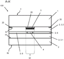
figure 2A showsbase:Sub>A cross-sectional view along cutting linebase:Sub>A-base:Sub>A' of figure 1,
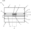
figure 2B showsbase:Sub>A cross-sectional view of an alternative embodiment along cutting linebase:Sub>A-base:Sub>A' of figure 1,
FIG. 2C showsbase:Sub>A cross-sectional view of an alternative embodiment along cut line A-A' of FIG. 1, and
figure 3 shows a detailed flow diagram of an embodiment of the method of the invention.
FIG. 1 shows a top view of an exemplary embodiment of an inventive glazing unit 101 having an inventive composite glazing panel 100, which is exemplified by a vehicle glazing panel, particularly a passenger car windshield panel.
The composite glass sheet 100 is, for example, substantially trapezoidal. The size of the composite glass plate 100 is, for example, 0.9mx 1.5m on its long side. The inner pane 2 is provided, for example, for facing the interior of the vehicle in the installed position. That is, the outer side surface IV of the inner glass pane 2 is accessible from the interior, while the outer side surface I of the outer glass pane 1 is directed outwardly with respect to the vehicle interior. The terms inside and outside refer to the inside and outside of the composite glass sheet, respectively. The outer glass pane 1 and the inner glass pane 2 consist, for example, of soda-lime glass. The thickness of the inner glass plate 2 is, for example, 1.6mm, and the thickness of the outer glass plate 1 is, for example, 2.1mm. It should be understood that the outer glass pane 1 and the inner glass pane 2 can have any thickness and can, for example, also be designed to have the same thickness.
The composite glass plate 100 may be, for example, architectural glass, furniture glass, or the like. Composite glass sheet 100 may be part of an insulating glass and is disposed, for example, in a window of a building. Alternatively, the composite glass sheet 100 may be disposed indoors and is, for example, the glass of a conference room or freezer cabinet or furniture.
An exemplary cross-sectional view along cut linebase:Sub>A-base:Sub>A' of fig. 1 is shown in fig. 2A. The composite glass pane 100 here comprises, for example, an outer glass pane 1 and an inner glass pane 2, which are joined to one another by means of two intermediate layers 3. Here, the first intermediate layer 3.1 is formed over the entire surface, while the second intermediate layer 6 is designed in the form of a frame.
In an exemplary embodiment, the electrical functional element 4, for example an OLED display, is integrated in the upper central region of the windscreen panel. Such OLED displays are very sensitive to temperature and degrade under UV radiation. A metal protective layer 5 is arranged between the functional element 4 and the outer glass plate 1. The protective layer 5 is arranged such that the functional element 4 is located completely in the region 10 of the orthogonal projection of the protective layer 5 relative to the outer glass pane 1. It is thereby ensured that IR and/or UV radiation 30 entering the composite glass pane 100 via the outer glass pane 1 is blocked by the protective layer 5 before impinging on the functional element 4. The metal protective layer 5 is made of, for example, an aluminum thin film with a thickness of 20 μm.
The intermediate layer 6 is arranged in a frame-like manner around the functional element 4 and the protective layer 5 and compensates for the height difference caused by the thickness of the functional element 4 and the protective layer 5.
The first interlayer 3 and the frame-like interlayer 6 may each consist of PVB, for example, and are fused to one another during the lamination process in the manufacture of the composite glass pane 100, while the outer glass pane 1 and the inner glass pane 2 are firmly and durably joined to one another.
In this embodiment, a cover print 20, for example black, is applied directly to the inside surface II of the outer glass pane 1, optionally between the protective layer 5 and the outer glass pane 1 and between the outer edge regions of the composite glass pane 100. The cover print 20 prevents a perspective through the composite pane 100 and a top view of the edge region of the composite pane 100, by means of which the composite pane is glued via the outer side surface IV of the inner pane 2, for example, into the frame of the vehicle body. In particular, a top view of the metallic protective layer 5, which usually emits a metallic luster and causes disturbing and less aesthetically pleasing reflections, is also prevented.
Due to the arrangement according to the invention of the metal protective layer 5 between the functional element 4 and the outer glass pane 1, UV and IR radiation 30 impinging on the outer glass pane 1 of the composite glass pane 100 from the outside is blocked. This leads to the avoidance of overheating or thermal damage of the functional element 4 in the case of IR radiation. By UV protection, degradation of the electronics of the functional element 4 is reduced or prevented. Both result in an extended service life and an increased operational safety of the functional element 4.
FIG. 2B shows an exemplary cross-sectional view of an alternative embodiment along cut line A-A' of FIG. 1. The composite glass pane 100 here corresponds essentially to the structure and material selection from the exemplary embodiment of fig. 2A. In contrast to fig. 2A, in fig. 2B a planar second intermediate layer 3.2 is arranged between the functional element 4 and the protective layer 5. This is particularly advantageous because the functional element 4 is reliably separated from the conductive metal protective layer 5 by the polymer and the electrically non-conductive material of the second intermediate layer 3.2.
FIG. 2C shows an exemplary cross-sectional view of an alternative embodiment along cutting line A-A' of FIG. 1. The composite glass pane 100 here corresponds essentially to the structure and material selection from the exemplary embodiment of fig. 2B. In contrast to fig. 2B, in fig. 2C a planar third intermediate layer 3.3 is arranged between the outer glass pane 1 and the protective layer 5. This is particularly advantageous, since the metal protective layer 5 is bonded reliably and durably to the outer glass pane 1 via the third intermediate layer 3.3.
It should be understood that in each of the embodiments of the composite glass sheet 100 of the present invention shown and not shown herein, the metallic protective layer 5 may be comprised of a self-supporting metallic layer or a polymeric carrier layer having a thin, separate or non-separate stable metallic layer.
Furthermore, the position of the functional element 4 with the protective layer 5 can be arranged arbitrarily and within the scope of the intended use in the region of the composite glass pane 100. Placement on the lower or side edges of the composite glass sheet 100 is preferred, particularly in the central field of view through the composite glass sheet 100. It is to be understood that the composite glass pane 100 according to the invention can also have a plurality of functional elements 4 with one or more connecting (zusammenh 228nd) or non-connecting protective layers 5.
FIG. 3 shows a flow chart of an embodiment of the inventive method of making the inventive composite glass sheet 100 of FIG. 2A, which includes the following method steps S1-S6.
S1: printing a cover print 20 on the inside surface II of the outer glass pane 1;
s2: a metal protective layer 5 is arranged, preferably by gluing, on the inner side surface II of the outer glass pane 1;
s3: the electrical functional elements 4 are arranged on the metallic protective layer 5, preferably by gluing, and a frame-like intermediate layer 6 surrounding the electrical functional elements 4 is arranged onto the inner side surface II of the outer glass pane 1;
s4: arranging a first intermediate layer 3.1 on the frame-like intermediate layer 6 and the functional element 4;
s5: arranging the inner glass sheet 2 on the first interlayer 3.1;
s6: the stack sequence is laminated to produce a composite glass sheet 100.
List of reference numerals
1. Outer glass plate
2. Inner glass plate
3. Intermediate layer
3.1 A first intermediate layer
3.2 Second intermediate layer
3.3 Third intermediate layer
4. Functional element
5. Protective layer
6. Frame-like intermediate layer
10. Projection area
20. Overlay printed matter, black printed matter
30. Infrared (IR) radiation and Ultraviolet (UV) radiation
100. Composite glass plate
101. Glass plate device
A-A' cutting line
Method steps S1, S2, S3, S4, S5, S6
I outer surface of the outer glass pane 1
II inner side surface of outer glass pane 1
III inner side surface of the inner glass pane 2
IV the outer side surface of the inner glass plate 2.
Claims (17)
1. Composite glass panel (100) comprising at least:
-an outer glass pane (1) and an inner glass pane (2) which are joined to each other by means of at least one intermediate layer (3),
-a functional element (4) arranged between the outer glass pane (1) and the inner glass pane (2),
wherein a metal protective layer (5) is arranged between the outer glass plate (1) and the functional element (4),
wherein the metallic protective layer (5) consists of a self-supporting metallic thin film having a thickness of 0.5 μm to 500 μm, wherein the metallic thin film reflects or absorbs at least 80% of the infrared radiation and/or ultraviolet radiation, such that the metallic thin film protects the functional element (4) from infrared radiation or ultraviolet radiation or both.
2. A composite glass sheet (100) according to claim 1, wherein said metal thin film is an aluminum thin film, a stainless steel thin film, a copper thin film, a silver thin film or a gold thin film.
3. The composite glass sheet (100) according to claim 1 or 2, wherein the thickness of the metal thin film is between 1 μm and 200 μm.
4. The composite glass sheet (100) according to claim 1 or 2, wherein the thickness of the metal thin film is between 20 μm and 50 μm.
5. Composite glazing panel (100) according to claim 1 or 2, wherein the area of the orthogonal projection of the metal film on the outer glazing panel (1) is equal to or greater than the area of the orthogonal projection of the functional element (4) on the outer glazing panel (1).
6. Composite glass pane (100) according to claim 1 or 2, wherein the metal film reflects or absorbs at least 90% of the infrared radiation and/or the ultraviolet radiation.
7. Composite glass pane (100) according to claim 1 or 2, wherein the metal film reflects or absorbs at least 99% of the infrared radiation and/or the ultraviolet radiation.
8. Composite glass pane (100) according to claim 1 or 2, wherein the functional element (4) is an electrically functional element and contains or consists of at least the following components:
-a light source,
-a display device for displaying the image data,
-a sensor for detecting the position of the object,
-an RFID chip, a switching logic circuit or a microprocessor.
9. Composite glass sheet (100) according to claim 8, wherein said light source is an LED light source or an OLED light source.
10. The composite glass sheet (100) according to claim 8, wherein said display is an OLED display.
11. The composite glass sheet (100) according to claim 8, wherein said sensor is a temperature sensor, a touch sensor, a humidity sensor, a vibration sensor, or a breakage sensor.
12. Composite glass pane (100) according to claim 1 or 2, wherein a cover print (20) is arranged between the outer glass pane (1) and the metal protective layer (5).
13. Composite glass pane (100) according to claim 12, wherein the cover print (20) is arranged directly onto the inner side surface II of the outer glass pane (1).
14. Composite glazing panel (100) according to claim 12, wherein said cover print (20) is a black print, a white print or a coloured print.
15. Method for producing a composite glass pane (100) according to claim 14, comprising at least:
(a) Preparing a stack sequence from at least one outer glass pane (1), a protective layer (5), a functional element (4), an intermediate layer (3) and an inner glass pane (2), and
(b) Laminating the sequence of stacks into a composite glass sheet (100).
16. Use of a composite glass pane (100) according to any one of claims 1 to 14 as a windshield pane, rear pane, side pane and/or roof pane in a land, water and air vehicle as well as a functional individual piece and as a component in furniture, appliances and buildings.
17. Use of a metallic protective layer (5) in a composite glass pane (100) according to any one of claims 1 to 14 for protecting functional elements from infrared and/or ultraviolet radiation.
Applications Claiming Priority (3)
| Application Number | Priority Date | Filing Date | Title |
|---|---|---|---|
| EP17208815.5 | 2017-12-20 | ||
| EP17208815 | 2017-12-20 | ||
| PCT/EP2018/082174 WO2019120849A1 (en) | 2017-12-20 | 2018-11-22 | Composite pane |
Publications (2)
| Publication Number | Publication Date |
|---|---|
| CN110177686A CN110177686A (en) | 2019-08-27 |
| CN110177686B true CN110177686B (en) | 2022-11-25 |
Family
ID=60702330
Family Applications (1)
| Application Number | Title | Priority Date | Filing Date |
|---|---|---|---|
| CN201880003334.0A Active CN110177686B (en) | 2017-12-20 | 2018-11-22 | Composite glass plate |
Country Status (6)
| Country | Link |
|---|---|
| EP (1) | EP3727844A1 (en) |
| JP (1) | JP7032539B6 (en) |
| KR (1) | KR102406247B1 (en) |
| CN (1) | CN110177686B (en) |
| MA (1) | MA51271A (en) |
| WO (1) | WO2019120849A1 (en) |
Families Citing this family (1)
| Publication number | Priority date | Publication date | Assignee | Title |
|---|---|---|---|---|
| DE202021004243U1 (en) | 2020-12-16 | 2023-03-21 | Saint-Gobain Glass France | glazing |
Citations (1)
| Publication number | Priority date | Publication date | Assignee | Title |
|---|---|---|---|---|
| CN106457779A (en) * | 2015-01-20 | 2017-02-22 | 法国圣戈班玻璃厂 | Composite pane with capacitive switching region |
Family Cites Families (7)
| Publication number | Priority date | Publication date | Assignee | Title |
|---|---|---|---|---|
| FR2752570B1 (en) * | 1996-08-22 | 1998-10-02 | Saint Gobain Vitrage | GLAZING WITH VARIABLE OPTICAL AND / OR ENERGY PROPERTIES |
| WO2005086557A1 (en) * | 2004-03-03 | 2005-09-15 | Bridgestone Corporation | Electromagnetic shielding light transmitting window material, display panel and method for manufacturing solar cell module |
| GB0408392D0 (en) * | 2004-04-15 | 2004-05-19 | Pilkington Plc | Electrically heated window |
| GB0705120D0 (en) * | 2007-03-16 | 2007-04-25 | Pilkington Group Ltd | Vehicle glazing |
| WO2014029536A1 (en) * | 2012-08-21 | 2014-02-27 | Saint-Gobain Glass France | Composite panel with electrically switchable optical properties |
| EP3106304A1 (en) * | 2015-06-19 | 2016-12-21 | AGC Glass Europe | Laminated glazing |
| EP3117991A1 (en) * | 2015-07-08 | 2017-01-18 | AGC Glass Europe | Automotive glazing |
-
2018
- 2018-11-22 MA MA051271A patent/MA51271A/en unknown
- 2018-11-22 WO PCT/EP2018/082174 patent/WO2019120849A1/en unknown
- 2018-11-22 CN CN201880003334.0A patent/CN110177686B/en active Active
- 2018-11-22 EP EP18808293.7A patent/EP3727844A1/en active Pending
- 2018-11-22 KR KR1020207020279A patent/KR102406247B1/en active IP Right Grant
- 2018-11-22 JP JP2020533709A patent/JP7032539B6/en active Active
Patent Citations (1)
| Publication number | Priority date | Publication date | Assignee | Title |
|---|---|---|---|---|
| CN106457779A (en) * | 2015-01-20 | 2017-02-22 | 法国圣戈班玻璃厂 | Composite pane with capacitive switching region |
Also Published As
| Publication number | Publication date |
|---|---|
| EP3727844A1 (en) | 2020-10-28 |
| JP2021506714A (en) | 2021-02-22 |
| WO2019120849A1 (en) | 2019-06-27 |
| CN110177686A (en) | 2019-08-27 |
| KR102406247B1 (en) | 2022-06-08 |
| JP7032539B2 (en) | 2022-03-08 |
| JP7032539B6 (en) | 2022-03-22 |
| KR20200091462A (en) | 2020-07-30 |
| MA51271A (en) | 2021-03-31 |
Similar Documents
| Publication | Publication Date | Title |
|---|---|---|
| KR101986031B1 (en) | Composite pane with capacitive switching region | |
| US6791065B2 (en) | Edge sealing of a laminated transparency | |
| CN110325359B (en) | Laminated glazing comprising an electrically controlled device and production | |
| CN107848270B (en) | Composite glass plate with multi-layer composite layer and manufacturing method thereof | |
| EP2218698B1 (en) | Laminated glass with inserted plastic film | |
| JP6659837B2 (en) | Method for producing a composite pane having an infrared reflective coating on a carrier film | |
| CA2993479C (en) | Heatable laminated vehicle window with improved heat distribution | |
| JP2019537213A (en) | A pane device having a composite pane having an extended capacitive switch area | |
| CN110177685B (en) | Composite glass plate device | |
| CN110636942B (en) | Composite glass pane having electrically switchable functional elements in a thermoplastic interlayer | |
| KR20220073838A (en) | Composite plate glass with integrated functional elements and degassing structure in the intermediate layer | |
| CN110177686B (en) | Composite glass plate | |
| CN114981078A (en) | Glazing with light source | |
| US11207868B2 (en) | Method for producing a laminated pane | |
| WO2006016961A1 (en) | Edge cauterized layered films, methods of manufacture, and uses thereof | |
| US20220123084A1 (en) | Laminated glass pane and method for the production thereof |
Legal Events
| Date | Code | Title | Description |
|---|---|---|---|
| PB01 | Publication | ||
| PB01 | Publication | ||
| SE01 | Entry into force of request for substantive examination | ||
| SE01 | Entry into force of request for substantive examination | ||
| GR01 | Patent grant | ||
| GR01 | Patent grant |