CN110101552B - An automatic sliding type assisting device to get up - Google Patents

An automatic sliding type assisting device to get up Download PDF

Info

Publication number
CN110101552B
CN110101552B CN201910366977.8A CN201910366977A CN110101552B CN 110101552 B CN110101552 B CN 110101552B CN 201910366977 A CN201910366977 A CN 201910366977A CN 110101552 B CN110101552 B CN 110101552B
Authority
CN
China
Prior art keywords
fixedly installed
sliding
base
motor
diamond
Prior art date
Legal status (The legal status is an assumption and is not a legal conclusion. Google has not performed a legal analysis and makes no representation as to the accuracy of the status listed.)
Active
Application number
CN201910366977.8A
Other languages
Chinese (zh)
Other versions
CN110101552A (en
Inventor
唐博
李浩溥
王明亮
Current Assignee (The listed assignees may be inaccurate. Google has not performed a legal analysis and makes no representation or warranty as to the accuracy of the list.)
Hefei Wisdom Dragon Machinery Design Co ltd
Original Assignee
Shenyang Aerospace University
Priority date (The priority date is an assumption and is not a legal conclusion. Google has not performed a legal analysis and makes no representation as to the accuracy of the date listed.)
Filing date
Publication date
Application filed by Shenyang Aerospace University filed Critical Shenyang Aerospace University
Priority to CN201910366977.8A priority Critical patent/CN110101552B/en
Publication of CN110101552A publication Critical patent/CN110101552A/en
Application granted granted Critical
Publication of CN110101552B publication Critical patent/CN110101552B/en
Active legal-status Critical Current
Anticipated expiration legal-status Critical

Links

Images

Classifications

    • AHUMAN NECESSITIES
    • A61MEDICAL OR VETERINARY SCIENCE; HYGIENE
    • A61HPHYSICAL THERAPY APPARATUS, e.g. DEVICES FOR LOCATING OR STIMULATING REFLEX POINTS IN THE BODY; ARTIFICIAL RESPIRATION; MASSAGE; BATHING DEVICES FOR SPECIAL THERAPEUTIC OR HYGIENIC PURPOSES OR SPECIFIC PARTS OF THE BODY
    • A61H3/00Appliances for aiding patients or disabled persons to walk about
    • A61H2003/001Appliances for aiding patients or disabled persons to walk about on steps or stairways
    • AHUMAN NECESSITIES
    • A61MEDICAL OR VETERINARY SCIENCE; HYGIENE
    • A61HPHYSICAL THERAPY APPARATUS, e.g. DEVICES FOR LOCATING OR STIMULATING REFLEX POINTS IN THE BODY; ARTIFICIAL RESPIRATION; MASSAGE; BATHING DEVICES FOR SPECIAL THERAPEUTIC OR HYGIENIC PURPOSES OR SPECIFIC PARTS OF THE BODY
    • A61H2201/00Characteristics of apparatus not provided for in the preceding codes
    • A61H2201/01Constructive details
    • A61H2201/0119Support for the device
    • AHUMAN NECESSITIES
    • A61MEDICAL OR VETERINARY SCIENCE; HYGIENE
    • A61HPHYSICAL THERAPY APPARATUS, e.g. DEVICES FOR LOCATING OR STIMULATING REFLEX POINTS IN THE BODY; ARTIFICIAL RESPIRATION; MASSAGE; BATHING DEVICES FOR SPECIAL THERAPEUTIC OR HYGIENIC PURPOSES OR SPECIFIC PARTS OF THE BODY
    • A61H2201/00Characteristics of apparatus not provided for in the preceding codes
    • A61H2201/12Driving means
    • A61H2201/1207Driving means with electric or magnetic drive
    • AHUMAN NECESSITIES
    • A61MEDICAL OR VETERINARY SCIENCE; HYGIENE
    • A61HPHYSICAL THERAPY APPARATUS, e.g. DEVICES FOR LOCATING OR STIMULATING REFLEX POINTS IN THE BODY; ARTIFICIAL RESPIRATION; MASSAGE; BATHING DEVICES FOR SPECIAL THERAPEUTIC OR HYGIENIC PURPOSES OR SPECIFIC PARTS OF THE BODY
    • A61H2201/00Characteristics of apparatus not provided for in the preceding codes
    • A61H2201/16Physical interface with patient
    • A61H2201/1602Physical interface with patient kind of interface, e.g. head rest, knee support or lumbar support
    • A61H2201/1635Hand or arm, e.g. handle
    • A61H2201/1638Holding means therefor
    • AHUMAN NECESSITIES
    • A61MEDICAL OR VETERINARY SCIENCE; HYGIENE
    • A61HPHYSICAL THERAPY APPARATUS, e.g. DEVICES FOR LOCATING OR STIMULATING REFLEX POINTS IN THE BODY; ARTIFICIAL RESPIRATION; MASSAGE; BATHING DEVICES FOR SPECIAL THERAPEUTIC OR HYGIENIC PURPOSES OR SPECIFIC PARTS OF THE BODY
    • A61H2201/00Characteristics of apparatus not provided for in the preceding codes
    • A61H2201/50Control means thereof
    • A61H2201/5058Sensors or detectors
    • A61H2201/5071Pressure sensors
    • AHUMAN NECESSITIES
    • A61MEDICAL OR VETERINARY SCIENCE; HYGIENE
    • A61HPHYSICAL THERAPY APPARATUS, e.g. DEVICES FOR LOCATING OR STIMULATING REFLEX POINTS IN THE BODY; ARTIFICIAL RESPIRATION; MASSAGE; BATHING DEVICES FOR SPECIAL THERAPEUTIC OR HYGIENIC PURPOSES OR SPECIFIC PARTS OF THE BODY
    • A61H2205/00Devices for specific parts of the body
    • A61H2205/06Arms

Landscapes

  • Health & Medical Sciences (AREA)
  • Epidemiology (AREA)
  • Pain & Pain Management (AREA)
  • Physical Education & Sports Medicine (AREA)
  • Rehabilitation Therapy (AREA)
  • Life Sciences & Earth Sciences (AREA)
  • Animal Behavior & Ethology (AREA)
  • General Health & Medical Sciences (AREA)
  • Public Health (AREA)
  • Veterinary Medicine (AREA)
  • Rehabilitation Tools (AREA)

Abstract

本发明公开了一种自动滑动式助力起身装置,包括滑动底座、连接座、菱形伸缩架、承载托座、传动皮带和压力传感器,其特征在于:所述滑动底座后壁左端固定安装驱动电机,驱动电机输出端贯穿滑动底座后壁后固定安装主动轮,滑动底座内部固定安装有均匀分布的定轴,定轴转动安装有辅助轮;利用最上面设有压力传感器的承载托座,使用者通过对承载托座的施压,使压力传感器感受到压力,压力转换为电流大小,电流传给控制伸缩支架的调节电机和控制传动皮带的驱动电机,通过得到的可控电流来控制调节电机与驱动电机的转速,这样可使承载托座保持水平,该装置是精确配置的,以便与操作者的移动速度完全相同,让使用者感到平稳。

Figure 201910366977

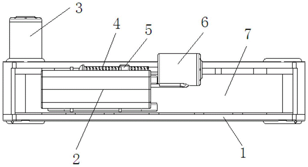
The invention discloses an automatic sliding type assisting getting up device, comprising a sliding base, a connecting seat, a diamond-shaped telescopic frame, a bearing bracket, a transmission belt and a pressure sensor, which is characterized in that a driving motor is fixedly installed on the left end of the rear wall of the sliding base, The output end of the drive motor runs through the rear wall of the sliding base, and then the driving wheel is fixedly installed. The fixed shaft is fixedly installed inside the sliding base, and the auxiliary wheel is installed to rotate on the fixed shaft. The pressure on the bearing bracket makes the pressure sensor feel the pressure, the pressure is converted into the current size, and the current is transmitted to the adjustment motor that controls the telescopic bracket and the drive motor that controls the transmission belt, and the control motor and drive are controlled by the obtained controllable current. The rotational speed of the motor, which keeps the carrying bracket level, the unit is precisely configured to move at exactly the same speed as the operator, giving the user a smooth feel.

Figure 201910366977

Description

Automatic slidingtype helping hand device of getting up
Technical Field
The invention belongs to the technical field of auxiliary rising devices, and particularly relates to an automatic sliding type power-assisted rising device.
Background
Along with the population ageing day by day, when getting up and climbing stair to some old person, because the reason of self physique, make the difficulty appear, and these difficulties are difficult to provide help through the auxiliary device of walking stick, the fixed length device of walking stick simultaneously, when using, because the unable regulation of its length, make its supplementary promotion height can appear the stage change because of its self length or step height, this kind of change is uncomfortable through limbs harmony to the old person, then need one kind to realize the device of slow regulation, supplementary old person gets up and climbs stair.
Disclosure of Invention
In order to solve the problems in the prior art, the invention provides a novel discharge chute with a combination of round pipes and square pipes, which can reduce the impact force of slurry, avoid slurry splashing in the discharging process, avoid the condition of corner area material collection when adopting the square pipe chute, prolong the novel chute cleaning period of the combination of the round pipes and the square pipes, thereby effectively improving the production efficiency and reducing the operation cost, and the technical scheme is as follows:
an automatic sliding type power-assisted rising device comprises a sliding base, a connecting seat, a diamond-shaped expansion bracket, a bearing bracket, a transmission belt and a pressure sensor, wherein a driving motor is fixedly installed at the left end of the rear wall of the sliding base, the output end of the driving motor penetrates through the rear wall of the sliding base and is fixedly installed with a driving wheel, fixed shafts which are uniformly distributed are fixedly installed in the sliding base, auxiliary wheels are rotatably installed on the fixed shafts, the transmission belt is sleeved between the driving wheel and the auxiliary wheels at the right end, an adjusting base is fixedly installed on the upper surface of the transmission belt, the left end of the adjusting base is hinged with the left lower foot of the diamond-shaped expansion bracket, the left upper corner of the diamond-shaped expansion bracket is hinged with the left end of the connecting seat, the right upper corner of the diamond-shaped expansion bracket is slidably installed in the connecting seat, the bearing bracket is fixedly installed at the upper end, the lead screw spiral shell dress thread bush, the front surface welded connection hinge of thread bush, the articulated rhombus expansion bracket right lower corner of connection hinge, bearing bracket upper surface fixed mounting has pressure sensor, and driving motor and accommodate motor are connected to the pressure sensor electricity.
The adjusting base comprises a front shell and a rear shell, a fixing hole is formed in the middle of the left end of the front shell, a sliding hole is formed in the front shell on the right side of the fixing hole, and the front shell and the rear shell are symmetrical L-shaped.
Two wheel carriers are fixedly arranged on the front edge and the rear edge of the lower surface of the sliding base, and the four wheel carriers are rotatably provided with rollers.
The front edge of sliding base lower surface fixed mounting two mounts, two mount fixed mounting threaded rod, the mount lower surface fixed mounting locating lever of lead screw both sides, threaded rod and the equal slidable mounting splint of locating lever, the threaded rod spiral shell dress adjusting screw section of thick bamboo of splint below.
Compared with the prior art, the invention has the beneficial effects that:
the invention utilizes the bearing bracket with the pressure sensor on the top, a user can make the pressure sensor feel pressure by applying pressure to the bearing bracket, the pressure is converted into current, the current is transmitted to the adjusting motor for controlling the telescopic bracket and the driving motor for controlling the driving belt, the rotating speeds of the adjusting motor and the driving motor are controlled by the obtained controllable current, the driving belt is arranged in the sliding base, the rhombic telescopic bracket and the driving belt are controlled by the pressure sensor, thus the bearing bracket can be kept horizontal, and the device is accurately configured so as to be completely the same as the moving speed of an operator, and the user can feel stable.
Drawings
FIG. 1 is a schematic top view of the present invention;
FIG. 2 is a schematic front view of the structure of embodiment 1 of the present invention;
FIG. 3 is a left side view schematically illustrating the structure of embodiment 1 of the present invention;
FIG. 4 is a schematic front view of the structure of embodiment 2 of the present invention;
FIG. 5 is a left side view schematically illustrating the structure of embodiment 2 of the present invention;
FIG. 6 is a schematic view of the assembly structure of the connecting base and the supporting bracket of the present invention;
FIG. 7 is a schematic view of the front housing of the adjusting base according to the present invention;
FIG. 8 is a schematic view of an adjusting base assembly according to the present invention;
fig. 9 is a schematic view of the internal structure of the sliding base according to the present invention.
In the figure: 1. the device comprises a sliding base, 2, a bearing bracket, 3, a driving motor, 4, a screw rod, 5, a threaded sleeve, 6, an adjusting motor, 7, a transmission belt, 8, a wheel carrier, 9, a roller, 10, an adjusting base, 101, a front shell, 102, a sliding hole, 103, a fixing hole, 104, a rear shell, 11, a connecting seat, 12, a diamond-shaped telescopic frame, 13, a fixing frame, 14, a clamping plate, 15, a positioning rod, 16, an adjusting screw cylinder, 17, a threaded rod, 18, a pressure sensor, 19, a driving wheel, 20, an auxiliary wheel, 21 and a fixed shaft.
Detailed Description
It should be noted that all the directional indicators (such as up, down, left, right, front, and rear … …) in the embodiment of the present invention are only used to explain the relative position relationship between the components, the movement situation, etc. in a specific posture (as shown in the drawing), and if the specific posture is changed, the directional indicator is changed accordingly.
Example 1
As shown in fig. 1, fig. 2, fig. 3, fig. 6, fig. 7, fig. 8 and fig. 9, the invention provides an automatic sliding type power-assisted uprisal device, which comprises a sliding base 1, a connecting seat 11, a diamond-shaped expansion bracket 12, a bearing bracket 2, a transmission belt 7 and a pressure sensor 18, wherein the sliding base 1 is a basic structure of the device and moves through a sliding driving device, the connecting seat 11 is a structure connecting the diamond-shaped expansion bracket 12 and the bearing bracket 2, and simultaneously provides a limiting station for the sliding of the upper end of the diamond-shaped expansion bracket 12, the diamond-shaped expansion bracket 12 drives the connecting seat 11 and the bearing bracket 2 to move up and down through the change of the shape of the diamond-shaped expansion bracket 12, a driving motor 3 is fixedly installed at the left end of the rear wall of the sliding base 1 to provide power for the movement of the device, a driving wheel 19 is fixedly installed at the rear, the sliding base 1 is internally and fixedly provided with fixed shafts 21 which are uniformly distributed and provide a limited installation foundation for the auxiliary wheel 20, the fixed shafts 21 are rotatably provided with the auxiliary wheel 20 to support the transmission belt 7, the transmission belt 7 is sleeved between the driving wheel 19 and the auxiliary wheel 20 at the right end and drives the adjusting base 10 to move through circulating rotation, the adjusting base 10 is fixedly arranged on the upper surface of the transmission belt 7 and provides a limited station for the relative movement of two feet at the lower end of the rhombic expansion bracket 12 through the self structure, the left lower foot of the rhombic expansion bracket 12 is hinged at the left end of the adjusting base 10 and is fixed for one foot of the rhombic expansion bracket 12 to avoid relative sliding and ensure that the adjustment cannot be carried out, the left upper corner of the rhombic expansion bracket 12 is hinged at the left end of the connecting seat 11 to realize effective rotating installation and simultaneously realize positioning and avoid separation and relative sliding to cause the movement failure of the, the upper right corner of a rhombic expansion bracket 12 is slidably arranged in a connecting seat 11 to realize auxiliary fixed connection, and meanwhile, the clamping is avoided through sliding to cause the device to be incapable of adjusting, a bearing seat 2 is fixedly arranged at the upper end of the connecting seat 11 to assist in adjusting the palm or arm of a user, meanwhile, an installation foundation is provided for a pressure sensor 18, an adjusting motor 6 is fixedly arranged at the right rear side of an adjusting base 10, the expansion of the rhombic expansion bracket 12 is adjusted through rotation, the axial direction of the adjusting motor 6 is parallel to the sliding direction of the rhombic expansion bracket 12, a lead screw 4 is fixedly arranged at the output end of the adjusting motor 6, a threaded sleeve 5 is moved through rotation, then the right lower foot of the rhombic expansion bracket 12 is driven to move to realize the adjustment of expansion, the lead screw 4 is screwed with the threaded sleeve 5 to realize the power transmission, a hinge is welded and connected on the front surface of, can rotate and realize power transmission, avoid the card to die, connect the articulated rhombus expansion bracket 12 lower right corner of hinge, in the rhombus expansion bracket 12 lower right corner slidable mounting adjusts base 10, slide through self, then adjust the relative position change with the lower left foot, realize flexible regulation, bearing bracket 2 upper surface fixed mounting has pressure sensor 18, it adopts JLLF type spoke pressure sensor 18, through the pressure of feeling, pressure of will standing up converts current signal into, control driving motor 3 and adjusting motor 6 work, driving motor 3 and adjusting motor 6 are connected to pressure sensor 18 electricity, realize effectual control circuit and connect.
Adjust base 10 and include preceding shell 101 and backshell 104, two parts are the main component structure of adjusting base 10, fixed orifices 103 has been seted up at preceding shell 101 left end middle part, provides the axle key installation basis for the left lower limb of fixed rhombus expansion bracket 12, slide opening 102 has been seted up to preceding shell 101 on fixed orifices 103 right side, makes things convenient for the hinge to slide in adjusting base 10, preceding shell 101 and backshell 104 are symmetrical L type, through integrated configuration, conveniently carry out the inner structure installation, and make things convenient for manufacturing.
Two mounts 13 of the leading edge fixed mounting of 1 lower surface of sliding base provide the installation basis for threaded rod 17, two mount 13 fixed mounting threaded rod 17, through self helicitic texture, realize the control to adjusting barrel 16, mount 13 lower surface fixed mounting locating lever 15 of threaded rod 17 both sides is injectd splint 14's slip, threaded rod 17 and the equal slidable mounting splint 14 of locating lever 15, cooperation mount 13 carries out the centre gripping location to the device, 4 spiral shell regulation barrels 16 of lead screw 4 spiral shell dress of splint 14 below realize control splint 14 positions through the spiral.
Example 2
As shown in fig. 1, 4, 5, 6, 7, 8 and 9, the invention provides an automatic sliding type power-assisted uprisal device, which comprises a sliding base 1, a connecting seat 11, a diamond-shaped expansion bracket 12, a bearing bracket 2, a transmission belt 7 and a pressure sensor 18, wherein the sliding base 1 moves through a sliding driving device as a basic structure of the device, the connecting seat 11 is a structure connecting the diamond-shaped expansion bracket 12 and the bearing bracket 2, and simultaneously provides a limiting station for the sliding of the upper end of the diamond-shaped expansion bracket 12, the diamond-shaped expansion bracket 12 drives the connecting seat 11 and the bearing bracket 2 to move up and down through the change of the shape of the diamond-shaped expansion bracket 12, a driving motor 3 is fixedly installed at the left end of the rear wall of the sliding base 1 to provide power for the movement of the device, a driving wheel 19 is fixedly installed at the rear end of the driving motor 3 after the output end of the driving, the sliding base 1 is internally and fixedly provided with fixed shafts 21 which are uniformly distributed and provide a limited installation foundation for the auxiliary wheel 20, the fixed shafts 21 are rotatably provided with the auxiliary wheel 20 to support the transmission belt 7, the transmission belt 7 is sleeved between the driving wheel 19 and the auxiliary wheel 20 at the right end and drives the adjusting base 10 to move through circulating rotation, the adjusting base 10 is fixedly arranged on the upper surface of the transmission belt 7 and provides a limited station for the relative movement of two feet at the lower end of the rhombic expansion bracket 12 through the self structure, the left lower foot of the rhombic expansion bracket 12 is hinged at the left end of the adjusting base 10 and is fixed for one foot of the rhombic expansion bracket 12 to avoid relative sliding and ensure that the adjustment cannot be carried out, the left upper corner of the rhombic expansion bracket 12 is hinged at the left end of the connecting seat 11 to realize effective rotating installation and simultaneously realize positioning and avoid separation and relative sliding to cause the movement failure of the, the upper right corner of a rhombic expansion bracket 12 is slidably arranged in a connecting seat 11 to realize auxiliary fixed connection, and meanwhile, the clamping is avoided through sliding to cause the device to be incapable of adjusting, a bearing seat 2 is fixedly arranged at the upper end of the connecting seat 11 to assist in adjusting the palm or arm of a user, meanwhile, an installation foundation is provided for a pressure sensor 18, an adjusting motor 6 is fixedly arranged at the right rear side of an adjusting base 10, the expansion of the rhombic expansion bracket 12 is adjusted through rotation, the axial direction of the adjusting motor 6 is parallel to the sliding direction of the rhombic expansion bracket 12, a lead screw 4 is fixedly arranged at the output end of the adjusting motor 6, a threaded sleeve 5 is moved through rotation, then the right lower foot of the rhombic expansion bracket 12 is driven to move to realize the adjustment of expansion, the lead screw 4 is screwed with the threaded sleeve 5 to realize the power transmission, a hinge is welded and connected on the front surface of, can rotate and realize power transmission, avoid the card to die, connect the articulated rhombus expansion bracket 12 lower right corner of hinge, in the rhombus expansion bracket 12 lower right corner slidable mounting adjusts base 10, slide through self, then adjust the relative position change with the lower left foot, realize flexible regulation, bearing bracket 2 upper surface fixed mounting has pressure sensor 18, it adopts JLLF type spoke pressure sensor 18, through the pressure of feeling, pressure of will standing up converts current signal into, control driving motor 3 and adjusting motor 6 work, driving motor 3 and adjusting motor 6 are connected to pressure sensor 18 electricity, realize effectual control circuit and connect.
Adjust base 10 and include preceding shell 101 and backshell 104, two parts are the main component structure of adjusting base 10, fixed orifices 103 has been seted up at preceding shell 101 left end middle part, provides the axle key installation basis for the left lower limb of fixed rhombus expansion bracket 12, slide opening 102 has been seted up to preceding shell 101 on fixed orifices 103 right side, makes things convenient for the hinge to slide in adjusting base 10, preceding shell 101 and backshell 104 are symmetrical L type, through integrated configuration, conveniently carry out the inner structure installation, and make things convenient for manufacturing.
The front edge and the rear edge of the lower surface of the sliding base 1 are both fixedly provided with two wheel frames 8 to provide a mounting base for the idler wheels 9, and the four wheel frames 8 are rotatably provided with the idler wheels 9 to facilitate the device to move on the stair handrail.
The above examples are only for illustrating the technical solutions of the present invention and not for limiting the same, and although the present invention is described in detail with reference to the above examples, those of ordinary skill in the art should understand that: modifications and equivalents may be made to the embodiments of the invention without departing from the spirit and scope of the invention, which is to be covered by the claims.

Claims (4)

1.一种自动滑动式助力起身装置,包括滑动底座、连接座、菱形伸缩架、承载托座、传动皮带和压力传感器,其特征在于:所述滑动底座后壁左端固定安装驱动电机,驱动电机输出端贯穿滑动底座后壁后固定安装主动轮,滑动底座内部固定安装有均匀分布的定轴,定轴转动安装有辅助轮,主动轮与右端的辅助轮之间套装传动皮带,传动皮带上表面固定安装调节底座,调节底座左端铰接菱形伸缩架的左下脚,菱形伸缩架左上角铰接连接座左端,菱形伸缩架右上角滑动安装连接座内,连接座上端固定安装承载托座,调节底座右后侧固定安装调节电机,调节电机的轴向与菱形伸缩架滑动方向平行,调节电机的输出端固定安装有丝杠,丝杠螺装螺纹套,螺纹套的前表面焊接连接铰轴,连接铰轴铰接菱形伸缩架右下角,承载托座上表面固定安装有压力传感器,压力传感器电连接驱动电机与调节电机。1. An automatic sliding type assisting getting up device, comprising a sliding base, a connecting seat, a diamond-shaped telescopic frame, a bearing bracket, a transmission belt and a pressure sensor, it is characterized in that: the left end of the rear wall of the sliding base is fixedly installed with a drive motor, and the drive motor The output end runs through the rear wall of the sliding base, and the driving wheel is fixedly installed. The fixed shaft is fixedly installed inside the sliding base. The fixed shaft is rotated and installed with an auxiliary wheel. A transmission belt is set between the driving wheel and the auxiliary wheel at the right end. Install the adjustment base fixedly, adjust the lower left foot of the diamond-shaped telescopic frame hinged on the left end of the base, the upper left corner of the diamond-shaped telescopic frame is hinged to the left end of the connection seat, the upper right corner of the diamond-shaped extension frame is slidably installed in the connection seat, the upper end of the connection seat is fixedly installed with the bearing bracket, and the right rear of the adjustment base is installed. The adjusting motor is fixedly installed on the side. The axial direction of the adjusting motor is parallel to the sliding direction of the diamond-shaped telescopic frame. The output end of the adjusting motor is fixedly installed with a lead screw. The lead screw is screwed with a threaded sleeve. The lower right corner of the hinged rhombus telescopic frame is fixedly installed on the upper surface of the bearing bracket, and the pressure sensor is electrically connected to the driving motor and the adjusting motor. 2.根据权利要求1所述的一种自动滑动式助力起身装置,其特征在于,所述调节底座包括前壳与后壳,所述前壳左端中部开设有固定孔,所述固定孔右侧的前壳开设有滑孔,所述前壳与后壳为对称L型。2 . The automatic sliding type power assisting device for getting up according to claim 1 , wherein the adjusting base comprises a front shell and a rear shell, and a fixing hole is opened in the middle of the left end of the front shell, and a right side of the fixing hole is opened. 3 . The front shell is provided with a sliding hole, and the front shell and the rear shell are symmetrical L-shaped. 3.根据权利要求1所述的一种自动滑动式助力起身装置,其特征在于,所述滑动底座下表面的前缘与后缘均固定安装两个轮架,四个所述的轮架转动安装滚轮。3 . The automatic sliding type power-assisted getting up device according to claim 1 , wherein two wheel frames are fixedly installed on the front edge and the rear edge of the lower surface of the sliding base, and the four wheel frames rotate. 4 . Install the rollers. 4.根据权利要求1所述的一种自动滑动式助力起身装置,其特征在于,所述滑动底座下表面的前缘固定安装两个固定架,两个所述的固定架固定安装螺纹杆,所述丝杠两侧的固定架下表面固定安装定位杆,所述螺纹杆与定位杆均滑动安装夹板,所述夹板下方的螺纹杆螺装调节螺筒。4 . The automatic sliding type power assisting device for getting up according to claim 1 , wherein two fixing frames are fixedly installed on the front edge of the lower surface of the sliding base, and the two fixing frames are fixedly installed with threaded rods. 5 . A positioning rod is fixedly installed on the lower surface of the fixing frame on both sides of the lead screw, the threaded rod and the positioning rod are both slidably installed with a splint, and the threaded rod below the splint is screwed with an adjusting screw cylinder.
CN201910366977.8A 2019-05-05 2019-05-05 An automatic sliding type assisting device to get up Active CN110101552B (en)

Priority Applications (1)

Application Number Priority Date Filing Date Title
CN201910366977.8A CN110101552B (en) 2019-05-05 2019-05-05 An automatic sliding type assisting device to get up

Applications Claiming Priority (1)

Application Number Priority Date Filing Date Title
CN201910366977.8A CN110101552B (en) 2019-05-05 2019-05-05 An automatic sliding type assisting device to get up

Publications (2)

Publication Number Publication Date
CN110101552A CN110101552A (en) 2019-08-09
CN110101552B true CN110101552B (en) 2021-05-14

Family

ID=67488170

Family Applications (1)

Application Number Title Priority Date Filing Date
CN201910366977.8A Active CN110101552B (en) 2019-05-05 2019-05-05 An automatic sliding type assisting device to get up

Country Status (1)

Country Link
CN (1) CN110101552B (en)

Citations (9)

* Cited by examiner, † Cited by third party
Publication number Priority date Publication date Assignee Title
JPH1147207A (en) * 1997-08-08 1999-02-23 Sakai Medical Co Ltd Walk supporting apparatus
JPH11299847A (en) * 1998-04-20 1999-11-02 Oshimayama Kiki:Kk Movement helping tool
CN103690341A (en) * 2013-12-03 2014-04-02 宁振平 Lifting double-crutch mechanical arm
CN103818859A (en) * 2012-11-18 2014-05-28 梁宇杰 Stairs climbing power assisting device and control method thereof
CN203736355U (en) * 2014-03-12 2014-07-30 金华职业技术学院 Elder standing frame
CN204379711U (en) * 2014-12-23 2015-06-10 上海理工大学 Help step lifter
CN105544899A (en) * 2015-12-13 2016-05-04 青岛智享专利技术开发有限公司 handrail for safety stairs
CN107041823A (en) * 2017-03-29 2017-08-15 浙江大学 Gait rehabilitation trainer and its method
US10080700B1 (en) * 2013-03-15 2018-09-25 Kourosh Bagheri Walker harness

Family Cites Families (1)

* Cited by examiner, † Cited by third party
Publication number Priority date Publication date Assignee Title
US9414987B2 (en) * 2013-03-15 2016-08-16 Entropy Enterprises, LLC Walker

Patent Citations (9)

* Cited by examiner, † Cited by third party
Publication number Priority date Publication date Assignee Title
JPH1147207A (en) * 1997-08-08 1999-02-23 Sakai Medical Co Ltd Walk supporting apparatus
JPH11299847A (en) * 1998-04-20 1999-11-02 Oshimayama Kiki:Kk Movement helping tool
CN103818859A (en) * 2012-11-18 2014-05-28 梁宇杰 Stairs climbing power assisting device and control method thereof
US10080700B1 (en) * 2013-03-15 2018-09-25 Kourosh Bagheri Walker harness
CN103690341A (en) * 2013-12-03 2014-04-02 宁振平 Lifting double-crutch mechanical arm
CN203736355U (en) * 2014-03-12 2014-07-30 金华职业技术学院 Elder standing frame
CN204379711U (en) * 2014-12-23 2015-06-10 上海理工大学 Help step lifter
CN105544899A (en) * 2015-12-13 2016-05-04 青岛智享专利技术开发有限公司 handrail for safety stairs
CN107041823A (en) * 2017-03-29 2017-08-15 浙江大学 Gait rehabilitation trainer and its method

Also Published As

Publication number Publication date
CN110101552A (en) 2019-08-09

Similar Documents

Publication Publication Date Title
CN203042684U (en) Multifunctional stair climbing wheel chair
CN210416608U (en) Adjustable shallow of laser radar
CN207681798U (en) A kind of automatic welder being moved easily
CN209518999U (en) A kind of autobalance multifunctional wheelchair
CN110101552B (en) An automatic sliding type assisting device to get up
CN215391722U (en) Flange straightening machine with positioning device
CN213323515U (en) Electric vehicle handlebar structure with lifting function
CN206923969U (en) A kind of nursing pillow
CN116673247B (en) Insulator cleaning auxiliary mechanism
CN107965647A (en) A kind of computer display adjustable support
CN220348289U (en) Sensor installation auxiliary device
CN213785822U (en) Cat ladder formula suitcase
CN114795861A (en) Clinical walking auxiliary device that uses of old psychiatric department
CN209442389U (en) Automatic deviation correction feeding roll mechanism
CN223542130U (en) A leg rehabilitation and walking aid
CN108938234A (en) Multi-functional wheelchair based on multinomial drive
CN210250490U (en) Moped convenient for infusion and walking of patient with drainage tube
CN106965207A (en) A kind of nursing robot footrest mechanism of retractable
CN206184649U (en) Adjustable bumper support frame
CN220632529U (en) Clinical walking auxiliary device that uses of old psychiatric department
CN218305363U (en) Electric stair-climbing wheelchair convenient to operate
CN114209506A (en) Multifunctional auxiliary device for assisting old people in sitting up
CN219332405U (en) Postoperative strutting arrangement
CN204813630U (en) Automatic rub back of body machine with hands
CN210929963U (en) Walking stick chair for assisting old people to sit up based on human factors

Legal Events

Date Code Title Description
PB01 Publication
PB01 Publication
SE01 Entry into force of request for substantive examination
GR01 Patent grant
GR01 Patent grant
TR01 Transfer of patent right

Effective date of registration: 20240718

Address after: 230000 b-1018, Woye Garden commercial office building, 81 Ganquan Road, Shushan District, Hefei City, Anhui Province

Patentee after: HEFEI WISDOM DRAGON MACHINERY DESIGN Co.,Ltd.

Country or region after: China

Address before: 110136, Liaoning, Shenyang moral and Economic Development Zone, No. 37 South Avenue moral

Patentee before: SHENYANG AEROSPACE University

Country or region before: China