CN1101013C - Engine accessory torque and engine deceleration rate determination method/system - Google Patents
Engine accessory torque and engine deceleration rate determination method/system Download PDFInfo
- Publication number
- CN1101013C CN1101013C CN95106048A CN95106048A CN1101013C CN 1101013 C CN1101013 C CN 1101013C CN 95106048 A CN95106048 A CN 95106048A CN 95106048 A CN95106048 A CN 95106048A CN 1101013 C CN1101013 C CN 1101013C
- Authority
- CN
- China
- Prior art keywords
- engine
- mentioned
- value
- controlled variable
- acces
- Prior art date
- Legal status (The legal status is an assumption and is not a legal conclusion. Google has not performed a legal analysis and makes no representation as to the accuracy of the status listed.)
- Expired - Fee Related
Links
Images


Classifications
-
- B—PERFORMING OPERATIONS; TRANSPORTING
- B60—VEHICLES IN GENERAL
- B60W—CONJOINT CONTROL OF VEHICLE SUB-UNITS OF DIFFERENT TYPE OR DIFFERENT FUNCTION; CONTROL SYSTEMS SPECIALLY ADAPTED FOR HYBRID VEHICLES; ROAD VEHICLE DRIVE CONTROL SYSTEMS FOR PURPOSES NOT RELATED TO THE CONTROL OF A PARTICULAR SUB-UNIT
- B60W10/00—Conjoint control of vehicle sub-units of different type or different function
- B60W10/04—Conjoint control of vehicle sub-units of different type or different function including control of propulsion units
- B60W10/06—Conjoint control of vehicle sub-units of different type or different function including control of propulsion units including control of combustion engines
-
- F—MECHANICAL ENGINEERING; LIGHTING; HEATING; WEAPONS; BLASTING
- F02—COMBUSTION ENGINES; HOT-GAS OR COMBUSTION-PRODUCT ENGINE PLANTS
- F02D—CONTROLLING COMBUSTION ENGINES
- F02D41/00—Electrical control of supply of combustible mixture or its constituents
- F02D41/02—Circuit arrangements for generating control signals
- F02D41/04—Introducing corrections for particular operating conditions
-
- B—PERFORMING OPERATIONS; TRANSPORTING
- B60—VEHICLES IN GENERAL
- B60W—CONJOINT CONTROL OF VEHICLE SUB-UNITS OF DIFFERENT TYPE OR DIFFERENT FUNCTION; CONTROL SYSTEMS SPECIALLY ADAPTED FOR HYBRID VEHICLES; ROAD VEHICLE DRIVE CONTROL SYSTEMS FOR PURPOSES NOT RELATED TO THE CONTROL OF A PARTICULAR SUB-UNIT
- B60W10/00—Conjoint control of vehicle sub-units of different type or different function
- B60W10/10—Conjoint control of vehicle sub-units of different type or different function including control of change-speed gearings
- B60W10/11—Stepped gearings
- B60W10/111—Stepped gearings with separate change-speed gear trains arranged in series
-
- B—PERFORMING OPERATIONS; TRANSPORTING
- B60—VEHICLES IN GENERAL
- B60W—CONJOINT CONTROL OF VEHICLE SUB-UNITS OF DIFFERENT TYPE OR DIFFERENT FUNCTION; CONTROL SYSTEMS SPECIALLY ADAPTED FOR HYBRID VEHICLES; ROAD VEHICLE DRIVE CONTROL SYSTEMS FOR PURPOSES NOT RELATED TO THE CONTROL OF A PARTICULAR SUB-UNIT
- B60W10/00—Conjoint control of vehicle sub-units of different type or different function
- B60W10/30—Conjoint control of vehicle sub-units of different type or different function including control of auxiliary equipment, e.g. air-conditioning compressors or oil pumps
-
- B—PERFORMING OPERATIONS; TRANSPORTING
- B60—VEHICLES IN GENERAL
- B60W—CONJOINT CONTROL OF VEHICLE SUB-UNITS OF DIFFERENT TYPE OR DIFFERENT FUNCTION; CONTROL SYSTEMS SPECIALLY ADAPTED FOR HYBRID VEHICLES; ROAD VEHICLE DRIVE CONTROL SYSTEMS FOR PURPOSES NOT RELATED TO THE CONTROL OF A PARTICULAR SUB-UNIT
- B60W30/00—Purposes of road vehicle drive control systems not related to the control of a particular sub-unit, e.g. of systems using conjoint control of vehicle sub-units, or advanced driver assistance systems for ensuring comfort, stability and safety or drive control systems for propelling or retarding the vehicle
- B60W30/18—Propelling the vehicle
- B60W30/19—Improvement of gear change, e.g. by synchronisation or smoothing gear shift
-
- F—MECHANICAL ENGINEERING; LIGHTING; HEATING; WEAPONS; BLASTING
- F16—ENGINEERING ELEMENTS AND UNITS; GENERAL MEASURES FOR PRODUCING AND MAINTAINING EFFECTIVE FUNCTIONING OF MACHINES OR INSTALLATIONS; THERMAL INSULATION IN GENERAL
- F16H—GEARING
- F16H59/00—Control inputs to control units of change-speed-, or reversing-gearings for conveying rotary motion
- F16H59/14—Inputs being a function of torque or torque demand
-
- F—MECHANICAL ENGINEERING; LIGHTING; HEATING; WEAPONS; BLASTING
- F16—ENGINEERING ELEMENTS AND UNITS; GENERAL MEASURES FOR PRODUCING AND MAINTAINING EFFECTIVE FUNCTIONING OF MACHINES OR INSTALLATIONS; THERMAL INSULATION IN GENERAL
- F16H—GEARING
- F16H61/00—Control functions within control units of change-speed- or reversing-gearings for conveying rotary motion ; Control of exclusively fluid gearing, friction gearing, gearings with endless flexible members or other particular types of gearing
- F16H61/70—Control functions within control units of change-speed- or reversing-gearings for conveying rotary motion ; Control of exclusively fluid gearing, friction gearing, gearings with endless flexible members or other particular types of gearing specially adapted for change-speed gearing in group arrangement, i.e. with separate change-speed gear trains arranged in series, e.g. range or overdrive-type gearing arrangements
- F16H61/702—Control functions within control units of change-speed- or reversing-gearings for conveying rotary motion ; Control of exclusively fluid gearing, friction gearing, gearings with endless flexible members or other particular types of gearing specially adapted for change-speed gearing in group arrangement, i.e. with separate change-speed gear trains arranged in series, e.g. range or overdrive-type gearing arrangements using electric or electrohydraulic control means
-
- B—PERFORMING OPERATIONS; TRANSPORTING
- B60—VEHICLES IN GENERAL
- B60W—CONJOINT CONTROL OF VEHICLE SUB-UNITS OF DIFFERENT TYPE OR DIFFERENT FUNCTION; CONTROL SYSTEMS SPECIALLY ADAPTED FOR HYBRID VEHICLES; ROAD VEHICLE DRIVE CONTROL SYSTEMS FOR PURPOSES NOT RELATED TO THE CONTROL OF A PARTICULAR SUB-UNIT
- B60W2510/00—Input parameters relating to a particular sub-units
- B60W2510/06—Combustion engines, Gas turbines
- B60W2510/0638—Engine speed
- B60W2510/0652—Speed change rate
-
- B—PERFORMING OPERATIONS; TRANSPORTING
- B60—VEHICLES IN GENERAL
- B60W—CONJOINT CONTROL OF VEHICLE SUB-UNITS OF DIFFERENT TYPE OR DIFFERENT FUNCTION; CONTROL SYSTEMS SPECIALLY ADAPTED FOR HYBRID VEHICLES; ROAD VEHICLE DRIVE CONTROL SYSTEMS FOR PURPOSES NOT RELATED TO THE CONTROL OF A PARTICULAR SUB-UNIT
- B60W2710/00—Output or target parameters relating to a particular sub-units
- B60W2710/06—Combustion engines, Gas turbines
- B60W2710/0666—Engine torque
-
- F—MECHANICAL ENGINEERING; LIGHTING; HEATING; WEAPONS; BLASTING
- F02—COMBUSTION ENGINES; HOT-GAS OR COMBUSTION-PRODUCT ENGINE PLANTS
- F02D—CONTROLLING COMBUSTION ENGINES
- F02D2200/00—Input parameters for engine control
- F02D2200/02—Input parameters for engine control the parameters being related to the engine
- F02D2200/10—Parameters related to the engine output, e.g. engine torque or engine speed
- F02D2200/1006—Engine torque losses, e.g. friction or pumping losses or losses caused by external loads of accessories
-
- F—MECHANICAL ENGINEERING; LIGHTING; HEATING; WEAPONS; BLASTING
- F16—ENGINEERING ELEMENTS AND UNITS; GENERAL MEASURES FOR PRODUCING AND MAINTAINING EFFECTIVE FUNCTIONING OF MACHINES OR INSTALLATIONS; THERMAL INSULATION IN GENERAL
- F16H—GEARING
- F16H59/00—Control inputs to control units of change-speed-, or reversing-gearings for conveying rotary motion
- F16H59/14—Inputs being a function of torque or torque demand
- F16H2059/145—Inputs being a function of torque or torque demand being a function of power demand of auxiliary devices
-
- F—MECHANICAL ENGINEERING; LIGHTING; HEATING; WEAPONS; BLASTING
- F16—ENGINEERING ELEMENTS AND UNITS; GENERAL MEASURES FOR PRODUCING AND MAINTAINING EFFECTIVE FUNCTIONING OF MACHINES OR INSTALLATIONS; THERMAL INSULATION IN GENERAL
- F16H—GEARING
- F16H59/00—Control inputs to control units of change-speed-, or reversing-gearings for conveying rotary motion
- F16H59/50—Inputs being a function of the status of the machine, e.g. position of doors or safety belts
-
- F—MECHANICAL ENGINEERING; LIGHTING; HEATING; WEAPONS; BLASTING
- F16—ENGINEERING ELEMENTS AND UNITS; GENERAL MEASURES FOR PRODUCING AND MAINTAINING EFFECTIVE FUNCTIONING OF MACHINES OR INSTALLATIONS; THERMAL INSULATION IN GENERAL
- F16H—GEARING
- F16H61/00—Control functions within control units of change-speed- or reversing-gearings for conveying rotary motion ; Control of exclusively fluid gearing, friction gearing, gearings with endless flexible members or other particular types of gearing
- F16H61/02—Control functions within control units of change-speed- or reversing-gearings for conveying rotary motion ; Control of exclusively fluid gearing, friction gearing, gearings with endless flexible members or other particular types of gearing characterised by the signals used
- F16H61/0202—Control functions within control units of change-speed- or reversing-gearings for conveying rotary motion ; Control of exclusively fluid gearing, friction gearing, gearings with endless flexible members or other particular types of gearing characterised by the signals used the signals being electric
- F16H61/0248—Control units where shifting is directly initiated by the driver, e.g. semi-automatic transmissions
-
- Y—GENERAL TAGGING OF NEW TECHNOLOGICAL DEVELOPMENTS; GENERAL TAGGING OF CROSS-SECTIONAL TECHNOLOGIES SPANNING OVER SEVERAL SECTIONS OF THE IPC; TECHNICAL SUBJECTS COVERED BY FORMER USPC CROSS-REFERENCE ART COLLECTIONS [XRACs] AND DIGESTS
- Y10—TECHNICAL SUBJECTS COVERED BY FORMER USPC
- Y10S—TECHNICAL SUBJECTS COVERED BY FORMER USPC CROSS-REFERENCE ART COLLECTIONS [XRACs] AND DIGESTS
- Y10S477/00—Interrelated power delivery controls, including engine control
- Y10S477/904—Control signal is acceleration
-
- Y—GENERAL TAGGING OF NEW TECHNOLOGICAL DEVELOPMENTS; GENERAL TAGGING OF CROSS-SECTIONAL TECHNOLOGIES SPANNING OVER SEVERAL SECTIONS OF THE IPC; TECHNICAL SUBJECTS COVERED BY FORMER USPC CROSS-REFERENCE ART COLLECTIONS [XRACs] AND DIGESTS
- Y10—TECHNICAL SUBJECTS COVERED BY FORMER USPC
- Y10T—TECHNICAL SUBJECTS COVERED BY FORMER US CLASSIFICATION
- Y10T74/00—Machine element or mechanism
- Y10T74/19—Gearing
- Y10T74/19219—Interchangeably locked
- Y10T74/19251—Control mechanism
Landscapes
- Engineering & Computer Science (AREA)
- Mechanical Engineering (AREA)
- Chemical & Material Sciences (AREA)
- Combustion & Propulsion (AREA)
- Transportation (AREA)
- General Engineering & Computer Science (AREA)
- Automation & Control Theory (AREA)
- Control Of Transmission Device (AREA)
- Control Of Vehicle Engines Or Engines For Specific Uses (AREA)
- Control Of Driving Devices And Active Controlling Of Vehicle (AREA)
- Electrical Control Of Air Or Fuel Supplied To Internal-Combustion Engine (AREA)
- Combined Controls Of Internal Combustion Engines (AREA)
Abstract
The invention provides an adaptive control system/method for an at least partially automated vehicular mechanical transmission system for determining the value of a control parameter (TACCES) indicative of accessory torque when the vehicle is in motion and the value of a control parameter (dES/dt rate) indicative of engine deceleration rate when the vehicle is not in motion. A relationship (dES/dt rate = A + B * TACCES) between engine deceleration rate and accessory torque is determined and allows derivation of one parameter from the other parameter during vehicle operating conditions wherein the other parameter may be directly determined from sensed inputs (TEG, TBEF, ES).
Description
The present invention relates to be used for is the part gear-shifting control method/system of vehicle mechanical kinematic train automatically at least, this type systematic comprises various gear shift control technology: for example such class technology, wherein successfully finish the requirement and/or the possibility of once selected gear up and judge according to the existing ruuning situation of vehicle, these situations be at least in part will with determine and/or be predefined on the driving wheel of vehicle the rate of deceleration of getable driving moment and/or engine be basis.Specifically, the present invention relates to when gear shift, to need not to throw off the such full-automatic or part of the master clutch of the vehicle used a kind of adaptive shift control method/system of vehicle mechanical kinematic train automatically, it can determine to show the driving wheel moment of vehicle and/or engine the rate of deceleration a value and use the controlled variable of these values as kinematic train.
More particularly, the present invention relates to a kind of adaptive shift control that is used for the automotive vehicle machine driven system, it is as the function of additional moment, constantly upgrade the control parameter value of the moment that shows engine flywheel, drive the characteristic (as engaging tooth speed ratio, tire size, efficient or the like) of system according to this value and some, the moment of driving wheel can be determined and/or constantly upgrade the value of the controlled variable that shows the engine retard rate exactly.For automatically or part vehicle mechanical kinematic train automatically, the rate of deceleration of wishing to know moment on the flywheel and/or engine is for use in many control algolithms.Known the moment on the flywheel and/or the engine retard rate just can be done more accurate gear shift control and make more advanced algorithm (for example gear shift ability and overall combination weight (GCM) calculating) become possibility.The moment information that control system of the present invention/method utilization comes from engine (preferably electronic engine) and the speed or the acceleration information of vehicle and engine calculate these controlled variable.
Utilizing the full-automatic or semi-automatic vehicle mechanical kinematic train of the electronic control unit electronic control unit of microprocessor (normally based on) is known in the prior art.The example of this class automatic mechanical transmission system can be with reference to United States Patent (USP) 3,961,546,4,361,060,4,425,620,4,631,679 and 4,648, No. 290, their disclosure be used as with reference to and be included in this.
The automatic vehicle drive system of another part utilize a kind of for machine driven system use automatically or semi-automatic transmission implementation system/method so that be used in the vehicle of the master clutch that has only manual control.This system has a kind of working method usually at least, and the gear shift that wherein needs automatic or semi-automatic enforcement is automatically previously selected.A kind of electronic control unit (ECU) is provided, show the signal of the speed of transmission input and output axle and/or engine speed and handle these signals with reception according to predetermined logic rules, thereby determine: (i) whether synchronous condition exists, (ii) under automatic preliminary election mode, whether need to do gear up or gear down from current engaged ratio, and send a command output so that make the kinematic train gear shift according to this command output to transmission topworks and/or engine fuel controller.
This universal kinematic train can be from United States Patent (USP) 5,050, and 079,5,053,959,5,053,961,5,053,962,5,063,511,5,081,588,5,089,965 and 5,272, see in No. 939, their disclosure be used as with reference to and be included in this.
Though above-mentioned vehicle mechanical kinematic train automatic and/or part fluid drive implementation type can be suitable for the application of their expections, but they can not make us satisfied fully, because they cause gear shift attempt sometimes, and this gear shift since the condition of work of vehicle can not allow and/or can not finish.This more need add attention under the situation of following gear up, do not provide the deceleration of automatic lookup clutch topworks and/or input shaft braking thereby input shaft to be limited under the situation of normal or the rate of deceleration that engine braking is auxiliary under heavily loaded situation and/or when climbing and/or in those automatic mechanical transmission systems as vehicle.
According to above-mentioned common unsettled U.S. Patent application 08/179,060 and United States Patent (USP) 5,272,939 and 5,133,229,5,172,609 and 5,231, No. 582 invention (their disclosure be used as with reference to and be included in this), the above-mentioned shortcoming of prior art can be by providing gear-shifting control method/system to be reduced to minimum to the vehicle that is the automatic machine driven system of part at least or being overcome, this type systematic when detecting the selection of the automatic or manual gear up that will turn to a certain target gear ratio from current engaging tooth speed ratio, can according to current detection to the vehicle operating condition determine this gear up of selecting whether feasible (promptly whether need and/or whether may finish), and only start those feasible gear shift.
If this gear up of planning to carry out is infeasible, then this gear shift requires can be modified (for example the gear shift of skipping a grade is made into the single-stage gear shift) or be cancelled in preset time section (for example 10 seconds).
The steering logic of top prior art is not entirely satisfactory, because showing the expensive axle torque sensor of value needs of the controlled variable of driving wheel obtains, and/or they are to derive from total engine moment value, wherein not have to consider because the moment that is installed in the annex (for example air conditioner, alternator etc.) on the vehicle assembly and the engine acceleration is consumed.For example, when heavy truck quickens under low gear, be a sizable numeral at oil at the moment number of being reported on the SAE J1939 type data link with the door open the time from engine.But, the major part of the moment that it of engine institute " report " is producing is to be used on the moment of inertia of acceleration motor and/or on the auxiliary device of powered vehicle, only some moment of reporting from flywheel through clutch coupling and go veritably vehicle is moved.
Above-mentioned prior art can not be made us fully satisfied part in addition because when vehicle stops and aperiodicity ground carry out and change the rate of deceleration that is difficult to determine desired engine when quickening shelves.
According to the present invention, the shortcoming of prior art can by to be at least part automatically the vehicle mechanical kinematic train provide a kind of adaptive control to be reduced to minimum or be overcome, this control can determine exactly under the current service condition of vehicle the value that shows the engine additional moment and as the engine flywheel torque of the function of additional moment; And determine to show the value of the rate of deceleration of engine.This control is specially adapted to the vehicular automated mechanical kinematic train of the communicating by letter with electronically controlled explosive motor by using a kind of data link that is consistent with the similar agreement of SAE J1922 or J1939.
In a preferred embodiment of the present invention, above said target be in a kind of vehicular automated mechanical legacy system control (it belongs to a kind of type of automatically not throwing off master clutch during at gear-change operation) by using the following relationship formula to finish:
T
EG=T
FW+T
BEF+T
ACCES+T
ACCEL
Herein:
T
EG=engine resultant couple;
T
FW=flywheel moment;
T
BEF=base engine moment of friction (comprising the moment that moment that overcomes the engine interior friction and the auxiliary device (as water pump, oil pump etc.) that engine shop is installed rotate);
T
ACCES=additional moment (required moments such as running vehicle optional equipment such as air conditioner, fan, illumination); With
T
ACCELThe moment of=acceleration motor is calculated and is obtained from the moment of inertia (I) of the acceleration of engine or retarded velocity and engine.
Expression engine resultant couple (T
EG) and basic engine friction moment (T
BEF) each instantaneous value can obtain from data link.T
ACCELDetermine from the corrected moment of inertia (I) of detected engine acceleration (it may be to bear) and engine.Additional moment (T
ACCES) be a value that constantly is determined, the applicant is definite, and gearing this additional moment under the situation of neutral gear and/or master clutch disengagement can be taken as the net torque (T of engine when vehicle is running down
EG-T
BEF), and vehicle be the rate of deceleration static or it and engine when starting with a kind of known be that linear mode is relevant basically.
When vehicle is static time running down, additional moment (T
ACCES) be to deduct basic moment of friction (T as resultant couple
EG-T
BEF) function and definite, the rate of deceleration of engine (dES/dt leads) is then derived by the known relation of the rate of deceleration of engine and additional moment.When vehicle ', the rate of deceleration of engine obtains by detection, preferably detects when the synchronous operation of gear up, and additional moment is then derived from the known relation of the rate of deceleration of engine and additional moment and got.
Therefore, provide a kind of part adaptive control system/method of machine driven system automatically that is at least that is used for vehicle, it constantly upgrades the controlled variable (T that shows additional moment
ACCES) value and show the value of the controlled variable (dES/dt leads) of the rate of deceleration of engine.These controlled variable are used to control the control operation of automatic mechanical transmission system.
This and other purpose of the present invention and advantage are by reading its DETAILED DESCRIPTION OF THE PREFERRED and will becoming very clear and definite in conjunction with appended accompanying drawing.
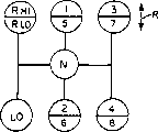
Fig. 1 is to realize the part synoptic diagram of vehicle mechanical kinematic train automatically by system of the present invention.
Figure 1A is the synoptic diagram of gear changing mode of the gearing of Fig. 1.
Fig. 2 is used for the automatic preliminary election of machine driven system of the present invention and the synoptic diagram of semi-automatic transmission implementation system.
Fig. 3 A is the synoptic diagram that is used for the signal of expression current vehicle speed and engine speed is carried out the logic of differential.
Fig. 3 B is the engine moment on being added to driving wheel calculates the logic that the vehicle acceleration of expection uses when being zero in gear shift moment a synoptic diagram.
Fig. 4 A and 4B are the synoptic diagram of the control method of the present invention represented with the process flow diagram form.
Fig. 5 is the diagrammatic representation of a gear up incident of the feasible and infeasible gear shift attempt of explanation.
Fig. 6 is the diagrammatic representation of engine speed and drive shaft speed similar with Fig. 5 during gear up.
Fig. 7 is additional moment (T
ACCES) and engine retard rate (dES/dt leads) between be essentially the diagrammatic representation of linear relation.
Some term will use in the following description, and this only is for for reference rather than restrictive." make progress ", speech such as " downwards ", " to the right ", " left " will indicate the direction among the figure that is used as reference.Speech such as " front ", " back " indicates the front-end and back-end that are placed in the gearing in the vehicle in the usual way respectively, and they are respectively the left side and the right side of kinematic train in Fig. 1." inwardly " and " outwards " two speech are represented towards and away from the direction of the geometric center of equipment respectively and are indicated wherein each part.The speech that above-mentioned term will be mentioned above will comprising specially, their derivation phrase and speech with similar implication.
Term " compound transmission " is used for illustrating change speed or changes gear drive, they have multiple pace main transmission section and the multiple speed auxiliary transmission section that is connected into series system, thereby selected gear reduction can further be made up by gear reduction selected in auxiliary transmission section in main drive.The speech of " synchronous clutch assembly " and similar implication should refer to a kind of clutch assembly, be used for selected class being coupled to axle non-rotatingly by means of a positive clutch, at this, the engagement attempt of this clutch coupling is prevented from before each parts of clutch coupling are in synchronous rotational speed basically.In the member of clutch coupling, used the rubbing device that has than the heavy load ability, when having caused the engagement of clutch coupling, be enough to make clutch coupling each parts and and its all parts of rotating together all to be synchronous speed rotation basically.
Term " gear up " is as employed here, should refer to from one than the gear shift to the gear ratio of fair speed of the gear ratio of low velocity.Term " low or first gear ", " low grade " and/or " first grade " all should refer to the gear ratio when being used for minimum pace operation in gearing or running part with here the time, promptly with respect to those group gear shelves of the maximum deceleration ratio of the input shaft of kinematic train.
With reference to figure 1, shown a kind of composite transmission 10 that is at least the change level type of part automatic type among the figure, it is realized by a semi automatic machine kinematic train with working method of automatic preliminary election.Composite transmission 10 comprises fast main transmission section 12 more than, and it and a change level type slave part 14 are connected in series.Kinematic train 10 is installed among the shell H and comprises an input shaft 16, this beam warp is crossed a master friction clutch C who throws off and be generally engagement selectively and by being driven such as the such prime mover of diesel motor E, this master friction clutch C has an input or drive part 18, it receives on the bent axle 20 of engine with type of drive, also have a driven portion 22, it is fixed on the input shaft 16 of kinematic train in rotating mode.
Engine E is by the fuel oil Throttle Opening Control, preferably control in the electronics mode, it is connected with electronic data link DL by the sort of type of SAE J1922 or 1939 agreement defineds, and master clutch C is manually operated by clutch pedal (not shown) or similar devices.Generally speaking, clutch coupling C is only just using to starting with under the situation that the fine motion of vehicle is operated from static.
With machine driven system 10 similar kinematic trains is well-known in prior art, can be with reference to United States Patent (USP) 3,105, and 395,3,283,613 and 4,754, to understand for No. 665, their disclosure is included in this with for referencial use.
The automatic vehicle mechanical kinematic train of the part of described type can be with reference to top said United States Patent (USP) 5,050,079,5,053,959,5,053,961,5,053,962,5,063,511,5,089,965 and 5,272, understands for No. 939.
Though control method/system of the present invention is specially adapted to those automatic mechanical transmission systems that does not have automatic lookup clutch topworks or input shaft braking, the present invention is not limited to these application.
In main transmission section 12, input shaft 16 has an input gear 24 so that drive a plurality of substantially the same intermediate shaft assemblies 26 and 26A simultaneously under substantially the same rotating speed.These two substantially the same intermediate shaft assemblies are radially being provided with the both sides of relative direction with it of main shaft 28, this main shaft usually always with input shaft 16 coaxial alignments.Each intermediate shaft assembly is included in the casing H by bearing 32 and 34 intermediate shafts of being supported 30, its part of only having drawn in the drawings.Each intermediate shaft all has identical countershaft- gear group 38,40,42,44,46 and 48, and they all are mounted fixing so that rotate therewith.A plurality of mainshaft gears 50,52,54,56 and 58 are centered around around the main shaft 28, can connect and rotation together with main shaft 28 selectively one at a time by the clutch ring 60,62 and 64 that slides, and this knows in prior art.Clutch ring 60 can also be used for input gear 24 is connected to main shaft 28 so that provide direct driving relationship between input shaft 16 and main shaft 28.
In general, clutch ring 60,62 and 64 is by means of being associated in selector fork together with gearbox case assembly 70 and in axial location, this also knows in prior art.Clutch ring 60,62 and 64 can be the non-synchronous type double acting jaw clutch type of knowing.
Gearbox case or topworks 70 can be by handling such as the such compressed fluid of pressurized air, and are can be by the controller the sort of type of control automatically, and this can be with reference to United States Patent (USP) the 4th, 445,393,4,555,959,4,361,060,4,722,237,4,873,881,4,928,544 and 2,931, No. 237 and see, their disclosure will be included in this as a reference.
Mainshaft gear 58 is back gear, and it meshes with countershaft-gear 48 continuously by means of common middle idle pulley (not shown).It should still be noted that, though main transmission section 12 determines to provide 5 kinds of selectable pace shelves, but minimum pace shelves (being that main shaft drives gear 56 is connected to that grade that main shaft 28 is provided with type of drive), usually its gear reduction ratio is so high, so that it must be considered to a kind of low speed or " creeping " shelves, it only is used for the situation of vehicle start under mal-condition, and generally is no under the high speed transmission range.Therefore, though main transmission section 12 determines to provide 5 kinds of paces, it b referred to as " 4 add 1 " main transmission section usually, because have only 4 kinds of paces and used auxiliary change level running part 14 to carry out compound transmission here.
Accessory drives becomes level part 14 and comprises substantially the same auxiliary intermediate shaft assembly 74 and 74A, each all comprises an auxiliary intermediate shaft 76 of being supported by the bearing among the casing H 78 and 80, and have two auxiliary transmission section countershaft- gears 82 and 84 and together the rotation.Auxiliary intermediate shaft 82 and become level/output gear 86 and always mesh together and support this gear, and auxiliary transmission section countershaft-gear 84 is frequent and output gear 88 meshes together.
In order to make compound gearing 10 be connected to output shaft 90 to gear 86 so that run on directly or level or gear 88 is connected to output shaft 90 carries out the operation of slow speed turbine stage at a high speed, a two-position synchronous jaw clutch group 92 is provided, and it is by means of the selector fork (not shown) and become level part gear-shifting actuating mechanism assembly 96 and in axial location." gear changing mode " synoptic diagram of gearing 10 that is used for compound change level type is shown in Figure 1A.
Becoming a level part topworks 96 can be United States Patent (USP) 3,648,546,4,440,037 and 4,614, and illustrated the sort of type in No. 126, its disclosure is included in this as a reference.
Become the double speed part of using spur gear or spiral gear type though become 14 expressions of level type slave part, but should be appreciated that, the present invention also is applicable to the gearing of the change level type of the slave part that uses three or more combined type transfer gear/changes grade types that can select gear ratio, and/or uses planetary gearing.In addition, any one in the clutch coupling 60,62 and 64 or a plurality of can be synchronous jaw clutch type, and running part 12 and/or 14 can be single intermediate shaft type.
For automatic preliminary election mode that operation is provided and gearing 10 automatically or the semi-automatic transmission implementation and operation, used drive shaft speed (IS) sensor and an output shaft speed (OS) sensor 100.If without output shaft speed sensor 100, also available sensors 102 is with the rotation rotary speed of the countershaft-gear 82 of detection slave part.Certainly, the rotational speed of gear 82 is known functions of main shaft 28 rotational speeies, if clutch coupling 92 is that then it also is the function of the rotational speed of output shaft 90 by a known position engagement.In addition, when master clutch C meshes fully, drive shaft speed (IS) will equal engine speed (ES).
The automatic preliminary election that is used for machine driven system of the present invention is implemented control system 104 with automatic or semi-automatic transmission and is shown schematically in Fig. 2.Control system 104 is except top illustrated machine driven system 10, also comprise one preferably based on the electronic control unit 106 of microprocessor, be used for from drive shaft speed sensor 98, from output shaft speed sensor 100 (perhaps also can from spindle speed sensor 102), from driver's control panel 108, from accelerator pedal position sensor 152 and by data link DL from engine E receiving inputted signal.In general, can obtain representing engine speed (ES), engine resultant couple (T at least from data link
EG) and basic engine friction moment (T
BEF) information.Electronic control unit (ECU) 106 also can receive input from auxiliary transmission section position transducer 110.
ECU106 can be at United States Patent (USP) 4,595, and the sort of type of meaning explanation shown in No. 986, its disclosure are included in that this is for reference.ECU can be effectively handle every input so that to the topworks such as electromagnetism house steward 112 (topworks 70 of its control main transmission section and the topworks 96 of the auxiliary transmission section) output signal of giving an order of kinematic train according to predetermined logic rules; ECU also to driver's control panel 108 and by data link DL to the engine E output signal of giving an order.
In a preferred embodiment, driver's control panel allows operating personnel manually to select a gear shift or change to neutral gear from the speed ratio of current engagement at assigned direction (up or down), perhaps select semi-automatic preselected operation mode (D), and preferably provide some demonstrations so that show current mode of operation (automatic or manual selection gear shift), current transmission ruuning situation (forward, backward or neutral gear) and selected but still unenforced any speed ratio change or gear shift (gear up, gear down or change to neutral gear) for the notifying operation personnel.
For the gear shift that realizes selecting, house steward 112 is arrived neutral gear by preliminary election so that make topworks 70 be biased to a main transmission section 12 gear shift.This is to cause oppositely finishing of moment by operating personnel or ECU controller by the fuel feeding that temporarily reduces and/or increase engine, and referring to United States Patent (USP) 4,850, No. 236, its disclosure is included in that this is for reference.When gearing is changed to neutral gear and ECU and confirmed, (detect neutral gear and need a period of time, for example 1.5 seconds), if selected gear shift is once-combined gear shift, be that this gear shift was both also carried out in change level running part 14 in main transmission section 12, that is for example seen in Figure 1A changes to the 5th grade of speed from the 4th grade of speed, and then ECU will give an order output signal so that make slave part topworks 96 become a level gear shift detecting to go to finish after front gear box has been in neutral gear to house steward 112.
When change level slave part had meshed with suitable speed ratio, ECU will be according to detected output shaft (vehicle) speed and the speed ratio (GR that need mesh
TARGET) and calculate or determine also constantly to upgrade allowed band or a speed band of a drive shaft speed with other method, it is acceptable synchromesh that this scope will cause the speed ratio that requires to mesh.When operating personnel or ECU make drive shaft speed be within this acceptable scope by the manipulation to throttle, ECU106 will be engaged on main transmission section on the required speed ratio to cause topworks 70 house steward 112 output signal of giving an order.
Under some service condition of vehicle, the gear shift that automatic or manual is selected can not be finished, and perhaps will cause unacceptable vehicle movement situation after having finished gear up.These conditions are usually directed to be under heavy duty and/or will overcome under steam under the situation of large drag forces and change under the situation of top gear when vehicle, these situations for example be travel in mire, climb very steep slopes and/or head on strong against the wind.
As an example, in order to reach synchronous basically condition finishing gear up one time, the speed of input shaft 10 (speed of the as many as engine E of this speed when master clutch meshes) must reduce so that the speed (it is proportional to car speed) that it is substantially equal to output shaft 90 multiply by the gear ratio of target.Owing to do not provide the braking of automatic lookup clutch topworks and input shaft, so the speed of input shaft will reduce with the attenuation rate of engine speed.Like this, realize synchronous condition basically in order to mesh under goals ratio, IS should as many as OS*GR
TARGET, when master clutch all meshed, IS should as many as ES simultaneously.
The order of a gear up of automatic mechanical transmission system described herein is shown among Fig. 5 with graphics mode.Line 200 is illustrated in the drive shaft speed (IS) under that vehicle condition before 202 of gear up, and wherein current gear ratio (GR) is all engagements, and master clutch C is all engagements, and ES=IS=OS*GR.When changing to neutral gear, along with the oil mass of engine reduces (promptly the fuel delivery to engine reduces to minimum), drive shaft speed and engine speed will be decayed till reaching running down speed according to represented continuous (but the not necessarily linear) speed (dIS/dt) of 204 lines.As desired speed (OS at the moment of gear shift output shaft 90 when the engine moment that is added to driving wheel of vehicle is zero
EXPECTED) with the product (this product is exactly the synchronous speed of needed input shaft/engine) of target gear ratio, be represented as line 208 and 210 in the drawings, they show respectively be to the resistance of vehicle movement for hour or the product when big.As can be seen, under the lower condition of resistance (line 208), will occur in synchronously a little on 212, at this moment selected gear up is feasible, and under the bigger situation of resistance (line 210), actually can not take place synchronously, thereby selected gear up is infeasible.
In the typical diesel motor of truck, the attenuation rate of engine/input shaft be about 300~800RPM (rev/min) and the retarded velocity of engine and vehicle can be approximately linear.The specific attenuation rate of engine and/or input shaft can be by obtaining No. the 4th, 361,060, above-mentioned United States Patent (USP) (for example, can with reference to) in the defuelling state value of ES and/or IS signal being carried out differential.But, attenuation rate can have very big variation along with the operating position of temperature and engine-driven auxiliary device.
Can see with reference to figure 5, if drive shaft speed (IS) (as by point on 202 initial input axle speed and the acceleration (dIS/dt) of input shaft determine like that) desired output shaft speed (OS when the as many as moment that is added on the driving wheel of vehicle of energy is zero
EXPECTED) (this desired speed is by initial OS (IS/GR) and determined to the vehicle acceleration (dOS/dt) under the current resistance of vehicle movement) and target gear ratio (GR
TARGET) numerical value multiply each other long-pending, and its value is greater than a certain reference value (as engine idle speed 206), then finishing synchronized shifting is feasible to selected target gear ratio, otherwise finishing synchronized shifting is infeasible to the target gear ratio of selecting.Certainly, OS and dOS/dt signal are equivalent to car speed and vehicle acceleration signal respectively.What shown reference value was used is the running down speed 206 of engine, but manually or is automatically thrown off as master clutch, then it also can be one lower on the occasion of.
In order to determine the purpose of feasibility, for the vehicle of overall combination weight (GCW) with very wide variation range (at this, GCW is vehicle, fuel, goods (if any), passenger's (if any) and operating personnel's a combination weight), controller can be determined current GCW.According to this information, system can determine how many acceleration (normally retarded velocity) line 208 of vehicle when drive system moment is zero or slopes of 210 should be, according to this information and the attenuation rate existing or engine that calculating gets, be the slope (its can become with the work of engine speed, working temperature, engine brake etc.) of line 204, ECU just can determine whether system can successfully finish the gear up that is proposed under the current vehicles service condition.According to this information, control system just can or (i) gear up of signal of giving an order to implement to be proposed, the perhaps gear up (usually the gear up of skipping a grade being made into simple gear up) that (ii) revise to propose, perhaps (iii) in one section preset time (for example can be about 10 seconds) cancel/forbid this gear shift request.
In brief, the acceleration of the vehicle following formula of can applying is greatly represented when the moment that is added to driving wheel is zero:
A
OTORQUE=A
i-(T
i/CW)
A herein
i=be added to the acceleration of driving wheel moment vehicle when being i at engine,
The C=constant,
T
i=be added to driving wheel engine moment i and
The gross combination weight of W=vehicle.
Fig. 3 A schematically illustrates logical block or the subroutine 220 that is used for the various input signals 222 as OS and/or ES and so on are carried out differential, to determine derivative dOS/dt and/or the dES/dt as its 224 pairs of times of output signal.
Fig. 3 B schematically illustrates a logical block or subroutine 226; Wherein, the various input signals 228 that comprise the signal of expression engine moment and vehicle acceleration (dOS/dt) will be handled determining an output signal 230 according to top logic rules of establishing, and this signal indication is at gear shift moment desired vehicle acceleration (dOS/dt) when not having engine moment to be added on the driving wheel of vehicle.
Be the explanation to a control system above, this system automatically estimates under current vehicle operating condition and manually or automatically realizes the feasibility of the gear shift of preliminary election, and the gear shift of this proposition is achieved, revises or is cancelled.If be confirmed as under infeasible situation at manually selected gear up, can to operating personnel send an energy sense of touch to, the alerting signal that maybe can see heard.
As explained above, in full-automatic or part automatic mechanical transmission system, concerning many control algolithms, hope can be known the moment (T on flywheel
FW) and/or the rate of deceleration (dES/dt leads) of engine.Known that the true moment on the flywheel and/or the rate of deceleration (dES/dt leads) of engine can obtain more accurate gear shift control and make some advanced algorithms, calculating as gear shift possibility and GCW becomes possibility.Flywheel moment is the function of additional moment.Control of the present invention has utilized the acceleration information of the moment information that comes from engine (preferably electronic engine) and vehicle and engine to calculate these controlled variable.
In order to control full-automatic or automanual vehicle mechanical kinematic train, important point is can determine to represent an exact value of driving wheel moment.If each parameter of drive system (as current driving cog speed ratio, driving shaft than, drive-train efficiency and tire size) is known, then the moment of driving wheel can be used as engine flywheel moment (promptly being added to the input torque on vehicle master clutch or the torque converter) function and be determined.
For the heavy vehicle that has electronically controlled engine and communicate on the data link by the type of SAE J1922 and J1939 agreement defined, engine moment can be represented by the formula:
T
EG=T
FW+T
BEF+T
ACCES+T
ACCEL
Herein: T
EG=engine resultant couple;
T
FW=flywheel moment;
T
BEF=basic engine friction moment;
T
ACCES=additional moment; With
T
ACCEL=be used for the moment of acceleration motor.
Engine resultant couple (T
EG) and basic engine friction moment (T
BEF) (equipment (as oil pump) that promptly drives engine shop and provided and overcome the required moment of engine interior friction force) be the parameter that can obtain from electronic data bus (DL).Moment (the T that acceleration motor is required
ACCEL) be function (T as the moment of inertia of detected engine acceleration and known engine
ACCEL=dES/dt*I
ENGINE) and determine.
Therefore, in order to determine flywheel moment (T
FW) (this is a controlled variable among gear shift possibility logic, GCW determine logic etc.), just be necessary to be provided for to determine additional moment (T
ACCES) control technology.Additional moment (T
ACCES) value have significant and frequent variation because the auxiliary device of vehicle such as illumination, air-conditioning, fans drive and so on can be automatically or are manually connected or turned off by the operating personnel of vehicle or passenger.
Suppose in the absence of engine retard (engine brake operation), just can observe the additional moment (T of engine in no external force
ACCES) and the variation of the rate of deceleration (dES/dt leads) of engine be complementary.The rate of deceleration of engine (dES/dt leads) is to be in neutral gear and/or master clutch is that whole disengagements and fuel delivery are the rates of deceleration that is in the engine of minimum when kinematic train.Along with the increase of additional load, the rate of deceleration of engine and its increase by direct ratio.
In order to control the automated mechanical kinematic train, also might need to determine the rate of deceleration (dES/dt) when the engine of vehicle not under motion conditions and/or when not carrying out gear shift.
When vehicle in motion with during in gear shift, the deceleration of engine is definite by following explanation.Automatic transmission system for type with engine of controlling by the electronic data link of the type of defined in SAE J1922 or J1939 agreement by ECU, engine was operated in one " falling in advance " (Predip) mode earlier before throwing off from existing speed ratio, after existing speed ratio is changed to neutral gear, then be operated in " synchronously " mode, and after and then being engaged to the target gear ratio, just be operated in " throttle recovery " mode.Engine and drive shaft speed under these modes are shown among Fig. 6.In " falling in advance " mode, the adjusting supplying fuel makes and drives is that moment is oppositely to remove the condition of moment locking.Under " synchronously " mode, it is minimum that engine oil is reduced to, and makes engine and drive shaft speed drop to synchronous speed so that be engaged to target gear ratio (ES=IS=OS*GR
TARGET).When " throttle recovery " mode, the supplying fuel of engine returns to by operating personnel smoothly to the represented value in gas pedal location.
In order under the situation of engine operation, to determine current engine retard rate value exactly in the method for synchronization, and in order to reduce noise, torsion etc. as far as possible, importantly, for each measurement, utilize the poor of the initial velocity of engine and the maximum possible between the final speed, and utilize a kind of filtering technique.Therefore, the value of the retarded velocity of determining to represent that engine is current, just must take the reading, and should be included near synchronized engine control stage first reading the some A in Fig. 6 when beginning to start in the synchronized engine control stage of gear up: and when the end of synchronized engine control maybe will finish in Fig. 6 B point or near second reading it.Like this, the currency (dES of engine retard rate
CURRENT) be exactly (RPM
A-RPM
B) ÷ (Time
A-Time
B).This value again through filtering to provide a controlled variable of having upgraded, for example:
dES
UPDATED=[(dES
CURRENT)+((7)*(dES
PREVIOUS))]÷8
The appearance that A is ordered is regarded as the initial time that is detected under the method for synchronization that is operated in.The appearance that B is ordered then is regarded as the initial time that is detected under the throttle reset mode that is operated in.Owing to do not have the variation (in about 40 milliseconds) that can record in intrinsic motivation speed cycling time that enters between the engine control subroutine of gear up, this is to obtain the peaked split hair method that engine speed changes during the synchronous working of each gear up.
Experience on heavy vehicle shows that the filtering technique between 4: 1 to 20: 1 (preferably being about 7: 1 filtering technique) will provide suitable responsiveness and can filter simultaneously because the noise of caused by factors drive systems such as vibration, torsion.
The invention provides that a kind of to be used to control be the part control method/system of vehicle mechanical kinematic train automatically at least, no matter vehicle is in motion or can be determined when stopping for additional moment and engine retard rate in this kinematic train.
When vehicle for stopping and engine is running down and kinematic train when being in neutral gear or master clutch and throwing off, additional moment (T
ACCES) be substantially equal to the engine resultant couple and deduct basic engine friction moment (T
EG-T
BEF).(T
EG-T
BEF) be also referred to as " engine net moment ".This value preferably from data bus or data link (DL) detects and preferably after filtration popin all handle calculating.
Provide relevant information to system controller, this information makes the rate of deceleration (dES/dt leads) and the additional moment (T of engine
ACCES) by one predetermined be that linear mode interrelates basically, the engine retard rate here equals A+ (B* additional moment), " A " and " B " is predetermined parameter of storing herein.If the unit that dES/dt leads is RPM/ second, T
ACCESUnit be lb-ft, then the unit of " A " is RPM/ second, the unit of " B " be RPM/ second/lb-ft.Fig. 7 is the graphic representation of this relation.
The value of relation of plane and additional moment before utilizing, the value of the engine retard rate of expection can be determined under vehicle is static state.Only be an approximate value when rate of deceleration of determining or deriving like this is used for vehicle launch to system logic, in case vehicle begins to start and during gear up just can with pass through filtering, actual detected to engine retard rate value proofread and correct and upgrade.
When vehicle is travelling and is carrying out gear up, the rate of deceleration of engine (dES/dt) can be when observing the fuel feeding that is in neutral gear and engine when kinematic train and reduce to minimum the engine retard rate of reality determine, and preferably to do the calculating of a filtering mean value to observed value.For example, can be with reference to above-mentioned common unsettled U.S. Patent Application Serial Number 08/__, its exercise question is " definite method/system of engine retard " (EngineDeceleration Determination Method/Sytem).Like this, additional moment (T
ACCES) can (be T just from same predetermined linear relationship discussed above
ACCES=(engine retard rate-A) ÷ B) determined.Utilize the example of Fig. 7, the engine retard rate equals-385+ (2*T
ACCES), be-500RPM/ during second, additional moment (T in the average engine retard rate (dES/dt leads) of observed process
ACCES) should equal 81.25 ppfs.
Though linear relationship is to be defined as predeterminedly for given vehicle structure, this relation also can be learnt adaptively by controller logic, is perhaps determined by experience at the end (end-of-line) of vehicle assembly line.For example, in order in the inspection of the end of vehicle assembly line and test process, to determine that this is linear relation basically, can follow the following step:
(1) heating makes it reach normal working temperature to vehicle motor;
(2) turn off all auxiliary devices (illumination, air-conditioning or the like), vehicle is parked on the neutral gear, makes engine accelerate to the speed of qualification then to put one's foot down, decontrol pedal then, monitor and record by maximum operational speed (promptly about 1, engine retard rate 800RPM);
(3) allow engine idle and observe additional moment by the data link of monitor engine, this be on Fig. 7 center line a bit.
(4) stop and starting all auxiliary devices during neutral gear at vehicle,, unclamp pedal then and monitor and the rate of deceleration of recording engine then by making engine accelerate to the speed of qualification to put one's foot down;
(5) make engine idle also pass through the monitoring data link to observe additional moment, this is second point on Fig. 7 center line; With
(6) utilize two such and definite points to determine this straight-line equation and corresponding correction value is sent into drive system controller.
Be noted that said process can manually carry out, perhaps also can be used as a routine in the computer logic of assembly line end correction.Another kind method is that a similar process can be incorporated in the logic of drive controller.
Utilize above-mentioned technology, an accurate T
FWValue (T
FW=T
EG-T
BEF-T
ACCES-T
ACCEL) and an engine retard rate value (dES/dt leads) can be determined.Additional moment (T of the present invention
ACCES), flywheel moment (T
FW) and definite method/system of engine retard rate (dES/dt leads) schematically in Fig. 4 A and 4B, be illustrated in a flowchart.
Therefore, as can be seen, provide a comparatively simple and cheap enforcement shift control/method that is used for automatic mechanical transmission system 10, it utilizes the engine retard rate (dES/dt leads) and the additional moment (T of existing input signal and no external force effect
ACCES) between fixed relation, provide accurately, show additional moment (T
ACCES), flywheel moment (T
FW) and the value of engine retard rate controlled variable such as (dES/dt lead).
Though the present invention illustrates with the singularity that has to a certain degree, should be appreciated that the spirit and scope that can make various changes in the form and details and not leave the invention that proposes claim in this application.
Claims (40)
1. method that is used for the automatic mechanical transmission system of vehicle, this kinematic train comprises the explosive motor (E) of a fuel oil Throttle Opening Control, the fuel oil throttle equipment (P) that the operator sets, many quick changes shelves mechanical driving device (10) that has input shaft (16) and be applicable to the output shaft (90) of powered vehicle driving wheel, above-mentioned input shaft is connected to above-mentioned engine with type of drive by a master friction clutch (C), this system also comprises a control module (106), this control module (106) is used to receive each input signal, comprising the input signal that shows input shaft or engine rotary speed (ES, IS), input signal (the T that shows the engine resultant couple
EG) and show the input signal (T of basic engine friction moment
BEF), this control module (106) also is used for handling above-mentioned signal to determine controlled variable and to each topworks of kinematic train output signal of giving an order according to the pre-logic rules of determining, these topworkies comprise and are used to the device (70) controlling the device of engine oil and be used to control the kinematic train gear shift, it is that running down and gearing are to be under the vehicle-state of throwing off at neutral gear and/or master clutch that this method is used at engine, determine the value of the controlled variable (dES/dt leads) of expression engine retard rate, above-mentioned method is characterised in that:
Determine engine retard rate (dES/dt leads) and additional moment (T
ACCES) between relation ((dES/dt leads)=A+ (B*T
ACCES));
Determine the controlled variable (T of expression additional moment
ACCES) value; With
Determine to show the value of above-mentioned controlled variable of the rate of deceleration of engine, it is to determine as the function of the value of the above-mentioned parameter that shows additional moment and above-mentioned relation.
2. method as claimed in claim 1 is characterized in that, wherein said input signal comprises the input signal (T that shows the engine resultant couple
EG) and show the input signal (T of basic engine friction moment
BEF), and the above-mentioned parameter (T of expression additional moment
ACCES) value be as the function of engine resultant couple and basic engine friction moment and determine.
3. method as claimed in claim 2 is characterized in that, wherein shows the above-mentioned parameter (T of additional moment
ACCES) value be as the function of following expression formula and definite:
T
ACCES=T
EG-T
BEF
4. method as claimed in claim 1 is characterized in that, the currency that the several Control parameter is at least wherein arranged in the said above-mentioned controlled variable is as through the mean value of filtering and definite.
5. method as claimed in claim 2 is characterized in that, wherein said engine and said control module communicate by electronic data link (DL), and this link transmits the above-mentioned engine resultant couple (T that shows
EG) and basic engine friction moment (T
BEF) signal.
6. method as claimed in claim 5 is characterized in that, wherein said data link meets in SAE J1922 and the J1939 agreement and carries out work.
7. method as claimed in claim 1 is characterized in that, wherein said relation is predetermined and is stored by above-mentioned control module.
8. method as claimed in claim 3 is characterized in that, wherein said relation is predetermined and by the storage of above-mentioned control module.
9. method as claimed in claim 1 is characterized in that, wherein said relation is linear.
10. method as claimed in claim 3 is characterized in that, wherein said relation is linear.
11. method as claimed in claim 1, it is characterized in that, wherein said kinematic train is carried out dynamically gear up to a target gear ratio by sequence of operation from the speed ratio of an engagement, wherein all operations all needn't be thrown off master clutch and do not considered the setting degree of operating personnel to throttle equipment, and this method comprises:
(a) one is fallen operation in advance, and wherein the fuel feeding of engine is conditioned so that the gear ratio that has meshed can be thrown off;
(b) after confirming to have thrown off the gear ratio that has meshed, a synchronous operation (wherein the fuel feeding of engine is reduced) reduces the rotational speed of engine and trends towards synchronous speed, so that mesh (ES=IS=OS*GR on goals ratio
T); With
(c) be the synchronous rotational speed of above-mentioned engine basically and make after engagement on the above-mentioned target gear ratio throttle recovery operation (wherein making the fuel feeding of engine be subjected to detected operating personnel controls the setting value of throttle equipment) reaching;
The above-mentioned value that shows the controlled variable (dES/dt leads) of the rate of deceleration of engine is determined that by a kind of method the method comprises when vehicle ':
When falling operation in advance, detection of engine speed;
Detect the initial point of above-mentioned synchronous operation, when detecting the initial point of above-mentioned synchronous operation, make detected engine speed equal engine speed initial value (RPM
A), and starting timing order;
Detect the initial point of throttle recovery operation, when detecting the initial point of above-mentioned throttle recovery operation, make engine speed equal engine speed end value (RPM
B), detect from the time of having been experienced since above-mentioned timing begins in proper order; And
Determine to show the currency of the controlled variable of engine retard rate, this value is to determine as the function of the time of difference between engine speed end value and the engine speed initial value and experience.
12. method as claimed in claim 1 is characterized in that, also comprise estimation as the function of the value of the above-mentioned controlled variable that shows the engine retard rate back with the feasibility of gear up.
13. method as claimed in claim 3 is characterized in that, also comprise estimation as a function of the value of the above-mentioned controlled variable that shows the engine retard rate back with the feasibility of gear up.
14. determine a controlled variable (T under the condition that is in motion at vehicle
ACCES) the method for value, this controlled variable shows the additional moment of the vehicle explosive motor (E) in the automatic mechanical transmission system of vehicle, this kinematic train comprises: the explosive motor of a fuel oil Throttle Opening Control (E), the fuel oil throttle equipment (P) that operating personnel set, many quick changes shelves mechanical driving device (10) that has input shaft (16) and be applicable to the output shaft (90) of powered vehicle driving wheel, above-mentioned input shaft is connected to above-mentioned engine with type of drive by a master friction clutch (C), this system also comprises a control module (106), be used to receive and comprise the input signal (ES that shows input shaft or engine rotary speed, IS) at each interior input signal, and be used for handling above-mentioned signal to determine controlled variable and to each topworks of kinematic train output signal of giving an order according to predetermined logic rules, these topworkies comprise and are used to the device (70) controlling the device of engine oil and be used to control the kinematic train gear shift that described method is characterised in that:
Determine at engine retard rate (dES/dt leads) and additional moment (T
ACCES) between relation ((dES/dt leads)=A+ (B*T
ACCES));
Determine to show the value of a controlled variable (dES/dt leads) of engine retard rate; With
Determine to show the above-mentioned controlled variable (T of additional moment
ACCES) a value, this value be as above-mentioned relation and show the engine retard rate above-mentioned controlled variable value function and determine.
15. the method as claim 14 is characterized in that, the above-mentioned currency that has Several Parameters in the wherein said above-mentioned controlled variable at least is as through the mean value of filtering and definite.
16. the method as claim 14 is characterized in that, wherein said engine and said control module show engine resultant couple (T by a transmission
EG) and basic engine friction moment (T
BEF) the electronic data link (DL) of signal communicate.
17. the method as claim 16 is characterized in that, wherein said data link is carried out work by meeting one of SAE J1922 or J1939 agreement.
18. the method as claim 14 is characterized in that, wherein said relation is to pre-determine and stored by above-mentioned control module.
19. the method as claim 14 is characterized in that, wherein said relation is linear.
20. as the method for claim 14, it is further characterized in that:
Determine to show a controlled variable (T of flywheel moment
FW) value, this value is as showing additional moment (T
ACCES) controlled variable above-mentioned value function and determine; With
As the above-mentioned flywheel moment (T that shows
FW) controlled variable value function and control the gear shift of kinematic train.
21. method as claim 14, it is characterized in that, wherein said kinematic train is carried out dynamic gear up to a target gear ratio by sequence of operation from the speed ratio of an engagement, wherein all operations all needn't be thrown off master clutch and do not considered the setting degree of operating personnel to throttle equipment, and this control method comprises:
(a) one is fallen operation in advance, and wherein the fuel feeding of engine is regulated and control so that the gear ratio that has meshed can be thrown off;
(b) after confirming to have thrown off the gear ratio that has meshed, a synchronous operation (wherein the fuel feeding of engine is reduced) makes the rotational speed of engine reduce and is tending towards synchronous speed, so that mesh (ES=IS=OS*GR on goals ratio
T); With
(c) be the synchronous rotational speed of above-mentioned engine basically and make that after engagement on the above-mentioned target gear ratio throttle recovery operation wherein makes the fuel feeding of engine be subjected to detected operating personnel the setting value of throttle equipment is controlled reaching;
The determining of the value of an above-mentioned controlled variable (dES/dt leads) to the rate of deceleration that shows engine comprises:
In the speed of falling detection of engine in the operation in advance;
Detect the initial point of above-mentioned synchronous operation, when detecting the initial point of above-mentioned synchronous operation, make detected engine speed equal engine speed initial value (RPM
A), and starting timing order;
Detect the starting point of throttle recovery operation, when detecting the starting point of above-mentioned throttle recovery operation, make engine speed equal engine speed end value (RPM
B), detect from the time of having been experienced since above-mentioned timing begins in proper order; With
Determine to show the currency of the controlled variable of engine retard rate, this value is to determine as the function of the time of difference between engine speed end value and the engine speed initial value and experience.
22. method as claim 17, it is characterized in that, wherein said kinematic train is carried out dynamically gear up to a target gear ratio by sequence of operation from the speed ratio of a certain engagement, wherein all operations all needn't be thrown off master clutch and do not considered the setting degree of operating personnel to throttle equipment, and this control method comprises:
(a) one is fallen operation in advance, and wherein the fuel feeding of engine is regulated and control so that the gear ratio that has meshed can be thrown off;
(b) after confirming to have thrown off the gear ratio that has meshed, a synchronous operation (wherein the fuel feeding of engine is reduced) makes the rotational speed reduction of engine and trends towards synchronous speed so that mesh (ES=IS=OS*GR on goals ratio
T); With
(c) be the synchronous rotational speed of above-mentioned engine basically and make that after engagement on the above-mentioned target gear ratio throttle recovery operation wherein makes the fuel feeding of engine be subjected to detected operating personnel the setting value of throttle equipment is controlled reaching;
The determining of the value of an above-mentioned controlled variable (dES/dt leads) to the rate of deceleration that shows engine comprises:
Detection of engine speed when falling operation in advance;
Detect the initial point of above-mentioned synchronous operation, when detecting the initial point of above-mentioned synchronous operation, make detected engine speed equal the initial (RPM of engine speed
A), and starting timing order;
Detect the initial point of throttle recovery operation, when detecting the initial point of above-mentioned throttle recovery operation, make engine speed equal engine speed end value (RPM
B), detect from the time of having been experienced since above-mentioned timing begins in proper order; With
Determine to show the currency of the controlled variable of engine retard rate, this value is to determine as the function of the time of difference between engine speed end value and the engine speed initial value and experience.
23. method that is used for the automatic mechanical transmission system of vehicle, this kinematic train comprises the explosive motor (E) of a fuel oil Throttle Opening Control, the fuel oil throttle equipment (P) that the operator sets, many quick changes shelves mechanical driving device (10) that has input shaft (16) and be applicable to the output shaft (90) of powered vehicle driving wheel, above-mentioned input shaft is connected to above-mentioned engine with type of drive by a master friction clutch (C), this system also comprises a control module (106), it is used to receive each input signal, comprising the input signal (ES that shows input shaft or engine rotary speed, IS), input signal (the T that shows the engine resultant couple
EG) and show the input signal (T of basic engine friction moment
BEF), it also is used for handling above-mentioned signal to determine controlled variable and to each topworks of kinematic train output signal of giving an order according to predetermined logic rules, these topworkies comprise and are used to the device (70) controlling the device of engine oil and be used to control the kinematic train gear shift that above-mentioned engine and above-mentioned control module show engine resultant couple (T by transmission
EG) and basic engine friction moment (T
BEF) above-mentioned signal an electronic data link (DL) and communicate, it is the value of a controlled variable (dES/dt leads) of the engine retard rate of running down and gearing or the master clutch explosive motor (E) of determining to show vehicle under for the vehicle condition of throwing off that described method is used at engine, and described method is characterised in that:
Determine at engine retard rate (dES/dt leads) and additional moment (T
ACCES) between relation ((dES/dt leads)=A+ (B*T
ACCES));
Determine to show the above-mentioned controlled variable (T of additional moment
ACCES) value, this value is to determine as the function of following expression formula:
T
ACCES=T
EG-T
BEF
With
Determine to show the engine retard rate above-mentioned controlled variable, a value, this value is to determine as the value of the above-mentioned parameter that shows additional moment and a function of above-mentioned relation.
24. the method as claim 23 is characterized in that, wherein the work of said data link accords with one of SAE J1922 or J1939 agreement.
25. the method as claim 24 is characterized in that, wherein said relation is to pre-determine and stored by above-mentioned control module.
26. the method as claim 24 is characterized in that, wherein said relation is linear.
27. a kind of control system in the vehicular automated mechanical kinematic train, this kinematic train comprises the explosive motor (E) of a fuel oil Throttle Opening Control, the fuel oil throttle equipment (P) that the operator sets, many quick changes shelves mechanical driving device (10) that has input shaft (16) and be applicable to the output shaft (90) of powered vehicle driving wheel, above-mentioned input shaft is connected to above-mentioned engine with type of drive by a master friction clutch (C), this system also has a control module (106), it is used to receive each input signal, comprising the input signal (ES that shows input shaft or engine rotary speed, IS), input signal (the T that shows the engine resultant couple
GE) and show the input signal (T of basic engine friction moment
BEF), it also is used for handling above-mentioned signal to determine controlled variable and to each topworks of kinematic train output signal of giving an order according to fixed logic rules, these topworkies comprise the device (70) that is used to control the device of engine oil and controls the kinematic train gear shift, it is that running down and gearing are in the value that neutral gear and/or master clutch determine to show a controlled variable (dES/dt leads) of engine retard rate under for the vehicle condition of throwing off that described control system is used at engine, and above-mentioned control system is characterised in that:
Be used to determine at engine retard rate (dES/dt leads) and additional moment (T
ACCES) between relation ((dES/dt leads)=A+ ((B*T
ACCES)) device;
Be used to determine to show a controlled variable (T of additional moment
ACCES) the device of value; With
Be used to determine to show the device of value of the above-mentioned controlled variable of engine retard rate, this value is to determine as the value of the above-mentioned parameter that shows additional moment and the function of above-mentioned relation.
28. the control system as claim 27 is characterized in that, wherein said each input signal comprises the input signal (T that shows the engine resultant couple
EG) and show the input signal (T of basic engine friction moment
BEF), and show the above-mentioned parameter (T of additional moment
ACCES) value be as the function of the engine friction moment of engine resultant couple and Qi Ben and definite.
29. the control system as claim 28 is characterized in that, shows the above-mentioned parameter (T of additional moment
ACCES) value be as the function of following expression formula and definite:
T
ACCES=T
EG-T
BEF。
30. the control system as claim 28 is characterized in that, above-mentioned engine and above-mentioned control module show engine resultant couple (T by a transmission
EG) and basic engine friction moment (T
BEF) described signal electronic data link (DL) and communicate by letter.
31. the control system as claim 30 is characterized in that, wherein the work of said data link accords with one of SAE J1922 or J1939 agreement.
32. the control system as claim 27 is characterized in that, wherein said relation is predetermined and is stored by above-mentioned control module.
33. the control system as claim 28 is characterized in that, also comprises the device of the feasibility that is used to estimate gear up subsequently, this gear shift is to estimate as the function of the value of the above-mentioned controlled variable that shows the engine retard rate.
34. a control system is used for determining a controlled variable (T when vehicle under driving conditions
ACCES) value, the additional moment of the vehicle explosive motor (E) of this parameter indicating in the vehicular automated mechanical kinematic train, this kinematic train comprises the explosive motor (E) of a fuel oil Throttle Opening Control, the fuel oil throttle equipment (P) that the operator sets, many quick changes shelves mechanical driving device (10) that has input shaft (16) and be applicable to the output shaft (90) of powered vehicle driving wheel, above-mentioned input shaft is connected to above-mentioned engine with type of drive by a master friction clutch (C), this system also comprises a control module (106), it is used to receive each input signal, comprise the input signal (ES that shows input shaft or engine rotary speed, IS), it also is used for handling above-mentioned signal to determine controlled variable and to each topworks of kinematic train output signal of giving an order according to fixed logic rules, these topworkies comprise the device of controlling engine oil and the device (70) of controlling the kinematic train gear shift, and described control system is characterised in that:
Be used to determine at engine retard rate (dES/dt leads) and additional moment (T
ACCES) between a kind of relation ((dES/dt leads)=A+ (B*T
ACCES)) device;
Be used to determine to show the device of value of a controlled variable (dES/dt leads) of engine retard rate;
Be used to determine to show the above-mentioned controlled variable (T of additional moment
ACCES) the device of value, this value be as above-mentioned relation and show the engine retard rate above-mentioned controlled variable value function and determine.
35. as the control system of claim 34, it is further characterized in that:
Be used to determine to show a controlled variable (T of flywheel moment
FW) the device of value, this value is as showing additional moment (T
ACCES) above-mentioned controlled variable value function and determine;
Be used for as showing flywheel moment (T
FW) above-mentioned controlled variable value function and control the device of the gear shift of kinematic train.
36. control system as claim 34, it is characterized in that, wherein said kinematic train by sequence of operation carry out from the speed ratio of an engagement dynamically gear up to a target gear ratio, wherein all operations all needn't be thrown off master clutch and do not considered the setting degree of operating personnel to throttle equipment, and it comprises:
(a) one is fallen operation in advance, and wherein the fuel feeding of engine is regulated and control so that the gear ratio that has meshed can be thrown off;
(b) after confirming to have thrown off the gear ratio that has meshed, a synchronous operation (wherein the fuel feeding of engine is reduced) makes the rotational speed reduction of engine and trends towards synchronous speed, so that meshes (ES=IS=OS*GR on goals ratio
T); With
(c) be the synchronous rotational speed of above-mentioned engine basically and make that after engagement on the above-mentioned target gear ratio throttle recovery operation wherein makes the fuel feeding of engine be subjected to detected operating personnel the setting value of throttle equipment is controlled reaching;
The device of the value of an above-mentioned controlled variable (dES/dt leads) that is used to determine to show the engine retard rate comprising:
At the device that falls operating period detection of engine speed in advance;
Be used to detect the initial point of above-mentioned synchronous operation and when detecting the initial point of this synchronous operation, make detected engine speed equal engine speed initial value (RPM
A) and start the device of timing order;
Be used to detect the initial point of throttle recovery operation and when detecting the initial point of this throttle recovery, make engine speed equal engine speed end value (RPM
B) and detect from the device of the time of having been experienced since above-mentioned positive time series begins;
Be used to determine show the device of the controlled variable currency of engine retard rate, this value is to determine as the function of the time of difference between engine speed end value and the engine speed initial value and experience.
37. a kind of control system in the automation mechanical driving system of vehicle, this kinematic train comprises the explosive motor (E) of a fuel oil Throttle Opening Control, the fuel oil throttle equipment (P) that the operator sets, many quick changes shelves mechanical driving device (10) that has input shaft (16) and be applicable to the output shaft (90) of the driving wheel of powered vehicle, above-mentioned input shaft is connected to above-mentioned engine with type of drive by a master friction clutch (C), this system also comprises a control module (106), it is used to receive each input signal, comprising the input signal (ES that shows input shaft or engine rotary speed, IS), the input signal (T that shows the engine resultant couple
EG) and show the input signal (T of basic engine friction moment
BEF), it also is used for handling above-mentioned signal to determine controlled variable and to each topworks of kinematic train output signal of giving an order according to fixed logic rules, these topworkies comprise the device (70) that is used to control the device of engine oil and is used to control the gear shift of kinematic train, and above-mentioned engine and above-mentioned control module show engine resultant couple (T by transmission
EG) and basic engine friction moment (T
BEF) above-mentioned signal an electronic data link (DL) and communicate, it is that running down and gearing or master clutch are the values of a controlled variable (dES/dt leads) of engine retard rate of determining to show the explosive motor (E) of vehicle under the vehicle condition of throwing off that described control system is used at engine, and this control system is characterised in that:
Be used to determine at engine retard rate (dES/dt leads) and additional moment (T
ACCES) between a kind of relation ((dES/dt leads)=A+ (B*T
ACCES)) device;
Be used to determine to show the above-mentioned controlled variable (T of additional moment
ACCES) the device of value, this value is to determine as the function of following expression formula;
T
ACCES=T
EG-T
BEF
With
Be used to determine to show the device of value of the above-mentioned controlled variable of engine retard rate, this value is to determine as the function of the value of the above-mentioned parameter that shows additional moment and above-mentioned relation.
38. the control system as claim 37 is characterized in that, wherein the work of said data link accords with one of SAE J1922 or J1939 agreement.
39. the control system as claim 38 is characterized in that, wherein said relation is predetermined and is stored by above-mentioned control module.
40. the control system as claim 37 is characterized in that, wherein said relation is linear.
Applications Claiming Priority (2)
| Application Number | Priority Date | Filing Date | Title |
|---|---|---|---|
| US08/242,824 US5582069A (en) | 1994-05-16 | 1994-05-16 | Engine accessory torque and engine deceleration rate determination method/system |
| US242824 | 1994-05-16 |
Publications (2)
| Publication Number | Publication Date |
|---|---|
| CN1125859A CN1125859A (en) | 1996-07-03 |
| CN1101013C true CN1101013C (en) | 2003-02-05 |
Family
ID=22916328
Family Applications (1)
| Application Number | Title | Priority Date | Filing Date |
|---|---|---|---|
| CN95106048A Expired - Fee Related CN1101013C (en) | 1994-05-16 | 1995-05-16 | Engine accessory torque and engine deceleration rate determination method/system |
Country Status (10)
| Country | Link |
|---|---|
| US (2) | US5582069A (en) |
| EP (1) | EP0683336B1 (en) |
| JP (1) | JPH0811590A (en) |
| KR (1) | KR100237839B1 (en) |
| CN (1) | CN1101013C (en) |
| AT (1) | ATE162281T1 (en) |
| BR (1) | BR9502095A (en) |
| CA (1) | CA2148163C (en) |
| DE (1) | DE69501427T2 (en) |
| ES (1) | ES2112610T3 (en) |
Families Citing this family (59)
| Publication number | Priority date | Publication date | Assignee | Title |
|---|---|---|---|---|
| US5582558A (en) * | 1995-07-27 | 1996-12-10 | Rockwell International Corporation | Combined system for assisting shifting of manual transmission |
| US5573477A (en) * | 1995-07-27 | 1996-11-12 | Rockwell International Corporation | Method and apparatus for assisting in shifting transmission to neutral |
| SE9600454L (en) * | 1996-02-07 | 1997-04-14 | Scania Cv Ab | Procedure for correction of the engine torque during shifting |
| DE19709417A1 (en) * | 1996-03-14 | 1997-10-30 | Luk Getriebe Systeme Gmbh | Control apparatus for torque transmitting system and automated transmission of motor vehicle |
| US5720696A (en) * | 1996-04-25 | 1998-02-24 | General Motors Corporation | Method of shift control using moment of inertia estimation |
| US6792344B2 (en) * | 1997-04-25 | 2004-09-14 | Hitachi, Ltd. | Automotive control apparatus and method |
| US6052638A (en) * | 1998-02-20 | 2000-04-18 | Eaton Corporation | Engine flywheel torque control |
| US5989155A (en) | 1998-04-01 | 1999-11-23 | Eaton Corporation | Engine fuel control for completing shifts in controller-assisted, manually shifted transmission |
| US6042504A (en) | 1998-04-01 | 2000-03-28 | Eaton Corporation | Range shift control |
| US5984831A (en) | 1998-04-01 | 1999-11-16 | Eaton Corporation | Adaptive upshift jaw clutch engagement control |
| US5911787A (en) | 1998-04-01 | 1999-06-15 | Eaton Corporation | Dynamic range shift actuation |
| IT1301760B1 (en) * | 1998-06-19 | 2000-07-07 | Ducati Energia Spa | METHOD AND DEVICE TO CONTROL THE IDLE ENGINE |
| US6113516A (en) * | 1999-01-14 | 2000-09-05 | Eaton Corporation | Adaptive automated transmission upshift control |
| US6149545A (en) * | 1999-01-14 | 2000-11-21 | Eaton Corporation | Automated transmission upshift control |
| US6325743B1 (en) | 1999-01-14 | 2001-12-04 | Eaton Corporation | Automated transmission upshift control |
| US6205389B1 (en) * | 1999-09-16 | 2001-03-20 | Eaton Corporation | Method/system for resetting the value of a control parameter indicative of gross combine weight of vehicles to a default value thereof |
| US6066071A (en) * | 1999-01-15 | 2000-05-23 | Eaton Corporation | Automated transmission downshift control |
| US6146310A (en) * | 1999-01-15 | 2000-11-14 | Eaton Corporation | Adaptive automated transmission downshift control |
| JP3624741B2 (en) * | 1999-05-17 | 2005-03-02 | 三菱自動車工業株式会社 | Control device for continuously variable transmission |
| US6123644A (en) * | 1999-07-19 | 2000-09-26 | Eaton Corporation | Adaptive anti-hunt logic for automated transmission downshift control |
| US6126569A (en) * | 1999-07-19 | 2000-10-03 | Eaton Corporation | Starting and driveline shock protection control method and system |
| US6226585B1 (en) * | 2000-04-18 | 2001-05-01 | Ford Global Technologies, Inc. | Torque estimation method for an internal combustion engine |
| US6409629B1 (en) | 2000-05-17 | 2002-06-25 | Eaton Corporation | Automated transmission upshift control with upshift brake thermal protection |
| US6491603B1 (en) | 2000-09-12 | 2002-12-10 | Eaton Corporation | Automated transmission shift control |
| US6502476B2 (en) | 2000-12-13 | 2003-01-07 | Eaton Corporation | Transmission system utilizing centrifugal clutch |
| US6526816B2 (en) * | 2000-12-13 | 2003-03-04 | Eaton Corporation | Transmission gear life monitor system |
| US6406403B1 (en) * | 2000-12-21 | 2002-06-18 | Eaton Corporation | Torque ramp down control |
| GB2371839A (en) * | 2001-02-01 | 2002-08-07 | Eaton Corp | Control for selecting automated transmission system shift strategy |
| US6539820B2 (en) | 2001-03-21 | 2003-04-01 | Eaton Corporation | Method and system for transmission utilizing centrifugal clutch to overcome transmission tooth-butt |
| US6641504B2 (en) | 2001-03-21 | 2003-11-04 | Eaton Corporation | Method and system for establishing an engine speed target for use by a centrifugal clutch control system to launch a vehicle |
| US6461273B1 (en) | 2001-06-01 | 2002-10-08 | Eaton Corporation | Automated transmission upshift brake control |
| US6633806B2 (en) | 2001-08-30 | 2003-10-14 | Eaton Corporation | Control for transmission system utilizing a centrifugal clutch |
| GB2389878A (en) * | 2002-06-18 | 2003-12-24 | Eaton Corp | Method of detecting false neutral in a transmission system |
| DE10330517A1 (en) * | 2003-07-05 | 2005-03-03 | Zf Friedrichshafen Ag | Method for controlling and regulating a transmission brake in a motor vehicle automatic transmission |
| US7480555B2 (en) | 2004-12-16 | 2009-01-20 | Eaton Corporation | Method for controlling centrifugal clutch engagement using engine torque requests |
| WO2007030070A1 (en) * | 2005-09-08 | 2007-03-15 | Volvo Lastvagnar Ab | Method and arrangement for adapting shifting strategies in a heavy vehicle including an automated transmission and experiencing a pto load |
| CN101263025B (en) * | 2005-09-08 | 2012-02-01 | 沃尔沃拉斯特瓦格纳公司 | Method for determining power output unit load of heavy vehicle of with mechanical type auto-transmission |
| JP2007315472A (en) * | 2006-05-25 | 2007-12-06 | Iseki & Co Ltd | Traveling device for tractor |
| US7324888B1 (en) * | 2006-10-02 | 2008-01-29 | Ford Global Technologies, Llc | Computationally efficient data-driven algorithms for engine friction torque estimation |
| US7905812B2 (en) * | 2007-02-02 | 2011-03-15 | Eaton Corporation | PTO brake |
| US8046140B2 (en) | 2008-01-18 | 2011-10-25 | Eaton Corporation | PTO overspeed protection strategy |
| DE102008040126A1 (en) * | 2008-07-03 | 2010-01-07 | Zf Friedrichshafen Ag | Method for controlling a switching process in an automatic transmission of a commercial vehicle |
| DE102011075913A1 (en) | 2011-05-16 | 2012-11-22 | Zf Friedrichshafen Ag | Method for determining a switching sequence of a ratio change of a transmission device of a vehicle drive train |
| DE102011080849A1 (en) | 2011-08-11 | 2013-02-14 | Zf Friedrichshafen Ag | Method for switching control of an automated group transmission |
| US8948977B2 (en) * | 2011-12-28 | 2015-02-03 | Caterpillar Inc. | Systems and methods for machine implement control |
| DE102012208881A1 (en) * | 2012-05-25 | 2013-11-28 | Robert Bosch Gmbh | Method for adapting torque loss of e.g. petrol engine for use in engine system for operating motor car, involves adapting torque loss of engine based on power consumption of electric motor determined during tow-starting of engine |
| JP6261347B2 (en) * | 2013-03-12 | 2018-01-17 | 泰三 嶋田 | Engine friction loss measuring method and engine driving state detecting method |
| US9267480B1 (en) * | 2013-05-10 | 2016-02-23 | The Boeing Company | Electrical power generating engine flywheel with active torque control |
| KR101484215B1 (en) * | 2013-06-19 | 2015-01-16 | 현대자동차 주식회사 | Method and system for starting engine when starter motor of hybrid electric vehicle is in trouble |
| CN103697154B (en) * | 2013-11-29 | 2016-04-27 | 浙江吉利控股集团有限公司 | A kind of process for gear of AMT automatic transmission |
| RU2550585C1 (en) * | 2014-01-17 | 2015-05-10 | Открытое акционерное общество "АВИАЦИОННЫЕ РЕДУКТОРА И ТРАНСМИССИИ - ПЕРМСКИЕ МОТОРЫ" (ОАО "Редуктор-ПМ") | Torque loading mechanism |
| JP2016057114A (en) * | 2014-09-08 | 2016-04-21 | 泰三 嶋田 | Method for measuring moment of inertia of engine and method for measuring friction loss of engine |
| DE102016211950A1 (en) * | 2016-06-30 | 2018-01-04 | Zf Friedrichshafen Ag | Method for transmission and damping of torques |
| DE102018207097A1 (en) * | 2018-05-08 | 2019-11-14 | Zf Friedrichshafen Ag | Torque determination for secondary consumers |
| CN111376892B (en) * | 2018-12-29 | 2022-07-15 | 河南森源重工有限公司 | Vehicle, and vehicle rotating hub test control method and device |
| DE102019216211A1 (en) * | 2019-10-22 | 2021-04-22 | Zf Friedrichshafen Ag | Method and control device for operating a drive train of a motor vehicle with a power take-off |
| CN113819234A (en) * | 2021-08-18 | 2021-12-21 | 潍柴动力股份有限公司 | Gear shifting auxiliary control method and vehicle |
| DE102022200615A1 (en) | 2022-01-20 | 2023-07-20 | Zf Friedrichshafen Ag | Motor vehicle transmissions, in particular electric vehicle transmissions |
| DE102022200607A1 (en) | 2022-01-20 | 2023-07-20 | Zf Friedrichshafen Ag | Motor vehicle transmissions, in particular electric vehicle transmissions |
Family Cites Families (23)
| Publication number | Priority date | Publication date | Assignee | Title |
|---|---|---|---|---|
| US3942365A (en) * | 1975-04-21 | 1976-03-09 | Rca Corporation | Power test means and method for internal combustion engines |
| US4361060A (en) * | 1978-01-24 | 1982-11-30 | Smyth Robert Ralston | Mechanical automatic transmission |
| DE3122362A1 (en) * | 1981-06-05 | 1983-01-05 | Xaver Fendt & Co, 8952 Marktoberdorf | Method for determining the instantaneous output of a drive motor |
| JPS59120748A (en) * | 1982-12-27 | 1984-07-12 | Nissan Motor Co Ltd | Estimating device for torque generated by engine |
| DE3416496A1 (en) * | 1984-05-04 | 1985-11-07 | Brown, Boveri & Cie Ag, 6800 Mannheim | METHOD AND CIRCUIT ARRANGEMENT FOR SIMULATING TEST DEGREE INERTIAL MOMENTS |
| GB8418749D0 (en) * | 1984-07-23 | 1984-08-30 | Eaton Ltd | Semi-automatic transmission control |
| US4595986A (en) * | 1984-10-09 | 1986-06-17 | Eaton Corporation | Method for control of automatic mechanical transmission system utilizing a microprocessor based electronic controller |
| US5231582A (en) * | 1989-03-29 | 1993-07-27 | Nissan Motor Company | Shifting control system for automotive automatic power transmission with enhanced variable shift pattern selection depending upon a resistance based upon vehicle acceleration and an engine parameter |
| US5053962A (en) * | 1989-06-19 | 1991-10-01 | Eaton Corporation | Automatic shift preselection mode for mechanical transmission system with semi-automatic shift implementation |
| US5053961A (en) * | 1989-06-19 | 1991-10-01 | Eaton Corporation | Semi-automatic shift implementation for mechanical transmission system |
| US5053959A (en) * | 1989-06-19 | 1991-10-01 | Eaton Corporation | Control system and method for sensing and indicating neutral in a semi-automatic mechanical transmission system |
| US5089965A (en) * | 1989-07-24 | 1992-02-18 | Eaton Corporation | Shift prohibiting for automatic shift preselection mode for mechanical transmission system with semi-automatic shift implementation |
| JP2827396B2 (en) * | 1990-02-16 | 1998-11-25 | トヨタ自動車株式会社 | Automatic transmission for vehicles |
| KR940009849B1 (en) * | 1990-04-17 | 1994-10-18 | 미쓰비시덴키가부시키가이샤 | Auto-transmission control device |
| US5241476A (en) * | 1990-05-08 | 1993-08-31 | Chrysler Corporation | Acceleration prediction responsive adaptive upshift control |
| JPH0494439A (en) * | 1990-08-09 | 1992-03-26 | Japan Electron Control Syst Co Ltd | Output display device for internal combustion engine |
| KR100289507B1 (en) * | 1991-12-03 | 2001-06-01 | 가나이 쓰도무 | Automatic shift control device and control method of vehicle |
| US5172609A (en) * | 1992-03-02 | 1992-12-22 | Saturn Corporation | Gradeability-based shift pattern control for an automatic transmission |
| DE4304779B4 (en) * | 1992-06-20 | 2005-11-24 | Robert Bosch Gmbh | Device for controlling the torque to be delivered by a drive unit of a vehicle |
| US5335566A (en) * | 1992-07-06 | 1994-08-09 | Eaton Corporation | Shift control method/system |
| US5425689A (en) * | 1992-07-06 | 1995-06-20 | Eaton Corporation | Engine brake enhanced upshift control method/system |
| US5272939B1 (en) * | 1992-07-06 | 1994-12-06 | Eaton Corp | Shift enable control method/system |
| US5608626A (en) * | 1993-03-26 | 1997-03-04 | Hitachi, Ltd. | Drive shaft torque controlling apparatus for use in a vehicle having a power transmission mechanism and method therefor |
-
1994
- 1994-05-16 US US08/242,824 patent/US5582069A/en not_active Expired - Lifetime
- 1994-09-21 US US08/309,713 patent/US5620392A/en not_active Expired - Lifetime
-
1995
- 1995-04-28 CA CA002148163A patent/CA2148163C/en not_active Expired - Fee Related
- 1995-05-01 DE DE69501427T patent/DE69501427T2/en not_active Expired - Fee Related
- 1995-05-01 AT AT95302963T patent/ATE162281T1/en not_active IP Right Cessation
- 1995-05-01 ES ES95302963T patent/ES2112610T3/en not_active Expired - Lifetime
- 1995-05-01 EP EP95302963A patent/EP0683336B1/en not_active Expired - Lifetime
- 1995-05-12 KR KR1019950011671A patent/KR100237839B1/en not_active IP Right Cessation
- 1995-05-15 BR BR9502095A patent/BR9502095A/en not_active IP Right Cessation
- 1995-05-16 JP JP7141136A patent/JPH0811590A/en active Pending
- 1995-05-16 CN CN95106048A patent/CN1101013C/en not_active Expired - Fee Related
Also Published As
| Publication number | Publication date |
|---|---|
| EP0683336B1 (en) | 1998-01-14 |
| ATE162281T1 (en) | 1998-01-15 |
| ES2112610T3 (en) | 1998-04-01 |
| CA2148163A1 (en) | 1995-11-17 |
| US5620392A (en) | 1997-04-15 |
| CN1125859A (en) | 1996-07-03 |
| EP0683336A1 (en) | 1995-11-22 |
| KR950033019A (en) | 1995-12-22 |
| KR100237839B1 (en) | 2000-01-15 |
| BR9502095A (en) | 1996-01-09 |
| JPH0811590A (en) | 1996-01-16 |
| DE69501427T2 (en) | 1998-09-03 |
| DE69501427D1 (en) | 1998-02-19 |
| CA2148163C (en) | 2000-05-30 |
| US5582069A (en) | 1996-12-10 |
Similar Documents
| Publication | Publication Date | Title |
|---|---|---|
| CN1101013C (en) | Engine accessory torque and engine deceleration rate determination method/system | |
| CN1101012C (en) | Engine flywheel torque determination method/system | |
| CN1113224C (en) | Method/system to determine gross combination weight of vehicles | |
| CN1040083C (en) | Shift control method/system | |
| CN1068550C (en) | Adaptive shift control method/system | |
| CN1066253C (en) | Driveline torque detection | |
| CN1153694C (en) | Independent control of gearbox side and engine side reduction device when changing transmission ratio | |
| CN1328101C (en) | Method and system for determining the torque required to launch a vehicle having a hybrid drive-train | |
| EP2127980B1 (en) | Transmission turbine acceleration control for managing vehicle acceleration | |
| EP2625444B1 (en) | System for selecting a transmission economy-based shift schedule | |
| CN1088520A (en) | Gearshift feasibility control method and control system | |
| CN105209798B (en) | Shift control device for vehicle | |
| CN1163368C (en) | Device for authorizing unrestricted operating mode of vehicle control device in event of failure of ignition signal | |
| CN1818430A (en) | Regenerative control apparatus for vehicles equipped with a lock-up clutch | |
| JPH0868460A (en) | Method and equipment for controlling shift of speed change gear | |
| CN1230647A (en) | Dynamic range shift actuation | |
| CN1174305A (en) | Automated transmission system corrtrol with zero engine flywheel torque determination | |
| WO2005028240A1 (en) | Method for regulating the rotational speed of a clutch-independent power take-off | |
| CN1662403A (en) | Drive means for motor vehicles | |
| CN1196876C (en) | Adaptive upshift jaw clutch engagement control | |
| EP1606529B1 (en) | System and method for controlling engagement of a clutch | |
| CN100357143C (en) | Start-from-stop engine torque limiting |
Legal Events
| Date | Code | Title | Description |
|---|---|---|---|
| C06 | Publication | ||
| PB01 | Publication | ||
| C10 | Entry into substantive examination | ||
| SE01 | Entry into force of request for substantive examination | ||
| C14 | Grant of patent or utility model | ||
| GR01 | Patent grant | ||
| C17 | Cessation of patent right | ||
| CF01 | Termination of patent right due to non-payment of annual fee |
Granted publication date: 20030205 Termination date: 20120516 |