CN110049722B - Systems and methods for facilitating respiratory state detection - Google Patents
Systems and methods for facilitating respiratory state detection Download PDFInfo
- Publication number
- CN110049722B CN110049722B CN201780076033.6A CN201780076033A CN110049722B CN 110049722 B CN110049722 B CN 110049722B CN 201780076033 A CN201780076033 A CN 201780076033A CN 110049722 B CN110049722 B CN 110049722B
- Authority
- CN
- China
- Prior art keywords
- patch
- sensor
- respiratory
- sensor signal
- respiratory airflow
- Prior art date
- Legal status (The legal status is an assumption and is not a legal conclusion. Google has not performed a legal analysis and makes no representation as to the accuracy of the status listed.)
- Active
Links
Images


Classifications
-
- A—HUMAN NECESSITIES
- A61—MEDICAL OR VETERINARY SCIENCE; HYGIENE
- A61B—DIAGNOSIS; SURGERY; IDENTIFICATION
- A61B5/00—Measuring for diagnostic purposes; Identification of persons
- A61B5/103—Detecting, measuring or recording devices for testing the shape, pattern, colour, size or movement of the body or parts thereof, for diagnostic purposes
- A61B5/11—Measuring movement of the entire body or parts thereof, e.g. head or hand tremor, mobility of a limb
- A61B5/113—Measuring movement of the entire body or parts thereof, e.g. head or hand tremor, mobility of a limb occurring during breathing
- A61B5/1135—Measuring movement of the entire body or parts thereof, e.g. head or hand tremor, mobility of a limb occurring during breathing by monitoring thoracic expansion
-
- A—HUMAN NECESSITIES
- A61—MEDICAL OR VETERINARY SCIENCE; HYGIENE
- A61B—DIAGNOSIS; SURGERY; IDENTIFICATION
- A61B5/00—Measuring for diagnostic purposes; Identification of persons
- A61B5/08—Detecting, measuring or recording devices for evaluating the respiratory organs
- A61B5/0803—Recording apparatus specially adapted therefor
-
- A—HUMAN NECESSITIES
- A61—MEDICAL OR VETERINARY SCIENCE; HYGIENE
- A61B—DIAGNOSIS; SURGERY; IDENTIFICATION
- A61B5/00—Measuring for diagnostic purposes; Identification of persons
- A61B5/08—Detecting, measuring or recording devices for evaluating the respiratory organs
- A61B5/087—Measuring breath flow
-
- A—HUMAN NECESSITIES
- A61—MEDICAL OR VETERINARY SCIENCE; HYGIENE
- A61B—DIAGNOSIS; SURGERY; IDENTIFICATION
- A61B5/00—Measuring for diagnostic purposes; Identification of persons
- A61B5/68—Arrangements of detecting, measuring or recording means, e.g. sensors, in relation to patient
- A61B5/6801—Arrangements of detecting, measuring or recording means, e.g. sensors, in relation to patient specially adapted to be attached to or worn on the body surface
- A61B5/683—Means for maintaining contact with the body
- A61B5/6832—Means for maintaining contact with the body using adhesives
- A61B5/6833—Adhesive patches
-
- A—HUMAN NECESSITIES
- A61—MEDICAL OR VETERINARY SCIENCE; HYGIENE
- A61B—DIAGNOSIS; SURGERY; IDENTIFICATION
- A61B2560/00—Constructional details of operational features of apparatus; Accessories for medical measuring apparatus
- A61B2560/04—Constructional details of apparatus
- A61B2560/0443—Modular apparatus
-
- A—HUMAN NECESSITIES
- A61—MEDICAL OR VETERINARY SCIENCE; HYGIENE
- A61B—DIAGNOSIS; SURGERY; IDENTIFICATION
- A61B2562/00—Details of sensors; Constructional details of sensor housings or probes; Accessories for sensors
- A61B2562/16—Details of sensor housings or probes; Details of structural supports for sensors
- A61B2562/164—Details of sensor housings or probes; Details of structural supports for sensors the sensor is mounted in or on a conformable substrate or carrier
Abstract
The invention relates to a system and a method for detecting a respiratory state, wherein the system comprises a flexible patch configured to be attached to the skin of a patient's body, wherein the patch comprises at least one sensor arrangement for sensing a physical activity of said patient's body when the patch is attached to the skin, and wherein the sensor arrangement is configured to determine and/or output a sensor signal corresponding to said physical activity. The system is configured to determine a respiratory airflow indicator based on the sensor signal. Alternatively or additionally, the system comprises a reusable additional device attachable to and detachable from the patch and adapted to provide energy to the patch and/or receive the sensor signal from the patch.
Description
The present invention relates to a system for facilitating respiratory state detection, a method for facilitating respiratory state detection, and a computer-readable storage medium.
The present invention relates generally to determining or determining a characteristic that depends on: respiratory tract, its tidal dynamics, its physiology and/or its geometry, these properties also being referred to as respiratory state.
The invention particularly relates to the field of identifying or facilitating identification of respiratory states so as to enable assessment or diagnosis of respiratory diseases such as, but not limited to, asthma with respect to airway obstruction or reduced airflow volume.
Furthermore, the invention relates to a wearable sensor device. Such wearable sensor devices are known from long-term examinations of patients, for example with regard to long-term blood pressure measurements or electrocardiograms.
WO 2016/053897 A1 relates to a wearable device configured for facilitating diagnosis and/or assessment of lung diseases. The device includes a flexible patch having an acoustic sensor, a movement sensor, a muscle activity sensor, a clock, an ambient temperature sensor, a communication port, a power source, a switching mechanism, a storage device, and one or more processors. The device records information including the acoustic signal on the memory device, which can be analyzed to identify one or both of an asthma attack or a cough attack.
US 6,019,732A discloses a device for monitoring tidal volume of a subject, the device comprising a flexible substrate for attachment to an animal or human. A sensing device comprising a series of semiconducting and conducting sensors is attached to the substrate and connectable into an electrical circuit. In response to changes in the expansion and contraction of the subject's lungs, the device reversibly changes its electrical resistance and thus converts changes in tidal volume into a signal output.
US 2002/0072685 A1 discloses a method and apparatus for monitoring and/or quantitatively measuring the respiration of a patient using a flexible piezoelectric film sensor. The device includes a flexible substrate that can be attached to the neck of a patient. The device also includes a piezoelectric film that converts sound waves generated by the patient's breathing into electrical signals.
US 201I/0301485 A1 discloses a data binning method and system for estimating a respiratory airflow of a subject from body sound signals detected by an acoustic sensor on the body of the subject. These methods and systems operate in a configuration mode followed by a monitoring mode. In the configuration mode, the body sound signal and the respiratory airflow are detected by the on-body acoustic sensor and the spirometer, respectively, over a common time period. Time-aligned body sound signal data points and respiratory airflow data points are then generated and associated with each other and stored in a look-up table. Then, in the monitoring mode, subsequent body sound signal readings are used to access a look-up table to provide a respiratory airflow estimate without the need for a spirometer.
US 2012/0041279 A1 and WO 2006/043278 A1 relate to systems and methods for stationary use, particularly in hospitals, which systems are not portable or wearable. The system comprises at least one sensor (in particular an electrode) placed on the body of the subject and connected by leads to a device which processes and analyses the measurements of the sensor and thus monitors the respiratory state and health condition of the subject continuously or intermediately. The systems and methods may maintain an alarm or adjust operating parameters of a ventilator that ventilates a subject when the breathing parameters reflect a loss of ventilation or other important function.
Although wearable devices are generally known to enable comfortable use for long periods of time, the known solutions are disposable items and are therefore very wasteful and expensive since the sensors must be replaced. On the other hand, conventional devices used for similar purposes, such as stethoscopes or spirometers, are less comfortable and are not suitable for continuous 24-hour monitoring and/or long-term use.
US 2015/0087922 A1 discloses a self-contained personal airflow sensing monitor. The wearable monitor comprises two components, an elongated flexible wearable electrode patch and a removable reusable monitor recorder. The monitor recorder may be mounted on and electrically connected to the electrode patch through contacts during patient monitoring and later removed to unload stored data or receive modified programming. The monitor recorder stores data received from the sensors of the patch in memory and may be connected to a download station to retrieve the stored data.
US 2013/0317333 A1 discloses a modular wearable sensor apparatus. The wearable sensor includes a first module having a first housing and a first printed circuit board within the first housing. The wearable sensor also includes a second module coupled to the first module, the second module having a second housing and a second printed circuit board within the second housing. One of the first module and the second module is disposable and the other of the first module and the second module is reusable.
WO 2014/128090 A1 discloses a device for respiratory monitoring having a disposable base for adhering to a patient's torso and a reusable electronic controller. The substrate includes a body in which two elongated transducers are embedded to measure deformation, the transducers being connected by conductors to a controller. The controller includes a plastic housing and is mechanically attached to the base using industrial grade hook and loop type fasteners.
Although these devices may be worn for longer periods of time and include a reusable portion, these solutions are still uncomfortable due to the rigid housing of the reusable portion. Another disadvantage is that the components must be connected electronically via galvanic contacts, limiting reliability, reusability and ease of use, and being less hygienic due to direct contact.
It is an object of the present invention to provide systems, methods and computer-readable storage media that are more efficient, resource-efficient, hygienic, and/or easier or more comfortable to use.
The object is achieved by a system for facilitating respiratory state detection, by a method for facilitating respiratory state detection, or by a computer readable storage medium.
One aspect of the invention relates to a system for facilitating detection of a respiratory state, wherein the system comprises a flexible patch configured to be attached or affixed to the skin of a patient's body, in particular to the skin in the chest area and/or to the skin in the respiratory tract area. The patch comprises at least one sensor, preferably a sensor arrangement, or at least a part of the sensor arrangement for sensing physical activity, in particular detecting chest activity, preferably different from cheyne-stokes respiration and/or corresponding to a respiratory state.
The one or more sensors or the sensor arrangement are configured to determine and/or output sensor signals corresponding to said chest activity or said physical activity. To this end, the sensor or sensor arrangement may be configured to detect or sense physical activity related to the respiratory state when the patch is attached or adhered to the skin. According to this aspect of the invention, the system is configured to determine and/or correlate to an indicator of respiratory airflow based on the sensor signal.
The respiratory airflow index preferably depends on or corresponds to or is associated with the airflow through the respiratory tract or system and/or the volume and/or velocity of air circulating in the respiratory tract or system. In particular, the respiratory airflow indicator is dependent on, corresponds to, includes or is the rate of airflow through the respiratory tract or respiratory system. Alternatively or additionally, the respiratory airflow indicator depends on or corresponds to or is associated with a characteristic change in the airflow through the respiratory system, and/or on a relative change in the volume and/or the relative change in the velocity of the air circulating in the respiratory tract or system.
The respiratory airflow index preferably corresponds to a respiratory state, i.e. corresponds to or depends on a characteristic that depends on: respiratory tract, its physiology, geometry or tidal dynamics. Alternatively or additionally, the respiratory airflow index corresponds to or is configured to enable detection of a change in respiratory state, i.e. a change in a characteristic of the respiratory tract: physiological changes in the respiratory tract, geometric changes in the respiratory tract, and/or tidal dynamics changes in the respiratory tract or within the respiratory tract.
The respiratory airflow index is typically known from or measurable by spirometry. In particular, the respiratory airflow index reflects, includes, or is formed by a so-called flow-volume loop, which is known to be generated by spirometry or corresponding data.
However, in the present invention, the respiratory airflow index is determined in a different manner than spirometry, i.e. with one or more sensors or sensor arrangements of wearable patches. The sensor signal used for this purpose can be converted into an indicator of the respiratory airflow, preferably allowing the use of techniques known from the analysis of spirometry results. Data collected using one or more sensors and/or respiratory airflow indicators may be output and/or further analyzed with or without being output.
It is well known that respiratory airflow rates are particularly suitable for assessing respiratory conditions, particularly identifying obstructions or flow restrictions within the respiratory tract. However, such respiratory airflow indicators determined by spirometry are not suitable for continuous monitoring or long-term use, nor do they allow wearing measuring equipment. However, wearable devices known in the art utilize different ways that do not allow for complex interpretation, such as directly recording and analyzing sounds.
Thus, generating the respiratory airflow indicator may be an intermediate step between the measurement by means of the sensor arrangement and the analysis, in particular by a medical professional and/or by a (partially) automatic analysis system. This intermediate step, i.e. the determination of the respiratory airflow index, comes with advantage. The respiratory airflow index includes additional information compared to the mere measurement or sensor signal. In particular, the determination of the respiratory airflow index adds information about the anatomy or condition of the respiratory tract, resulting in measurements-in particular by interpretation and/or correlation to anatomically relevant benchmarks. Thus, the respiratory airflow index enables a more reliable and comfortable determination of the respiratory state.
An indicator of respiratory flow, or a portion thereof, may be determined from the sensor signal by comparison with or correlation with a reference signal, such as a sample, that assigns a sensor signal segment, or data corresponding to a characteristic of the sensor signal, to the indicator of respiratory flow, or a portion thereof. Such a reference signal may therefore replace the sensor signal in order to form and/or may be used to determine an indicator of respiratory airflow.
In other words, the invention combines the advantages of tidal breathing measurements and the advantages of wearable devices in a synergistic manner, since the sensor signals originating at least partly from the wearable patch are used to determine a respiratory airflow indicator in a first step, and the respiratory airflow indicator can be analyzed in a second step as easily and reliably as the results from a tidal breathing measurement instrument, while in particular avoiding the use of tidal breathing measurements such as spirometers.
Another aspect of the invention, which may also be implemented independently, relates to a system for facilitating respiratory state detection, wherein the system includes a flexible patch configured to be attached or affixed to a patient's skin of a patient's body. The patch comprises at least one sensor, preferably a sensor arrangement, for detecting or sensing physical activity of said patient's body when the patch is attached or adhered to the skin, and/or for detecting or sensing chest activity, and/or corresponding to the respiratory state of the patient's body. The sensor or sensor arrangement is configured to determine and/or output a sensor signal preferably corresponding to said physical activity, in particular chest activity. The system comprises a reusable additional device that is attachable and/or retainable to and/or detachable from the patch and that is adapted to provide energy to the patch and/or receive the sensor signal from the patch.
According to this aspect, since the patch has two layers, one of which is a reusable add-on device and the other of which is configured to be directly attached and held on the skin, it will not be necessary to dispose of the entire wearable patch after use. Thus, it is neither necessary to have sensor wires from the wearable patch to a measurement recorder or the like, nor to have a measurement recorder or the like to form part of the patch and to do so after use.
This aspect of the invention further provides the advantage that only such sensors that are or need to be in direct contact with the body will be part of the patch, and other sensors or parts thereof that are not and/or need not be in contact with the body may be part of additional devices.
Preferably, the patch and the add-on device are adapted to transmit and/or receive sensor signals and/or energy wirelessly and/or without direct electrical (galvanic) contact. In particular, the signal transfer and/or the energy transfer can be inductive and/or capacitive. The patch and/or the additional device may comprise means for energy transfer and/or signal transfer, such as an electrical coil and/or a capacitor. Advantageously, direct electrical contact of the patch with additional equipment may be avoided, thereby providing a more reliable, reusable and/or hygienic system.
Preferably, the additional device is patch-like and/or formed as a patch. In particular, the additional device may be flexible and/or adhesive. The add-on device preferably has its components arranged on or embedded in a (flexible) substrate, in particular without any additional housing or the like. Particularly preferably, the additional device is formed at least substantially similarly to the patch. In particular, the components of the add-on device and the components of the patch may be arranged in a similar or corresponding manner. This advantageously increases wearing comfort and ease of use and/or is beneficial for manufacturing the proposed system in a cost-effective manner.
Yet another aspect of the invention, which may also be implemented independently, relates to a method for facilitating respiratory state detection using a patch configured to be either attached or affixed to the skin of a patient's body. The patch comprises a sensor, preferably a sensor arrangement, or at least a part of the sensor arrangement, for sensing physical activity of the patient's body. The sensor or sensor arrangement is configured to determine and/or output a sensor signal corresponding to said physical activity. An indicator of respiratory airflow is determined (preferably calculated) based on the sensor signal. Alternatively or additionally, the patch is powered and/or the sensor signal is received from the patch by a reusable add-on device attachable to and detachable from the patch. Accordingly, corresponding effects and advantages can be achieved.
Yet another aspect of the invention, which may also be implemented independently, relates to a preferably non-transitory computer-readable storage medium or computer program product comprising program code means or instructions configured, when executed, particularly on a processor, controller or similar computing device, to perform a method according to the invention or to cause a computer, processor or controller to perform the steps of a method according to the invention.
A "patch" according to the invention is preferably a flat device with a flat surface configured for long-term direct contact with the skin. In particular, the surface comprises or is formed by an adhesive layer configured to adhere to skin. The adhesive layer preferably (preferably at least substantially or completely) covers the side of the patch arranged to be in direct contact with the skin. However, there may also be regions without an adhesion layer. The patch is preferably flexible in such a way that it follows the shape and/or movement of the skin and/or so that it can be torn in order to follow the shape of the skin.
Preferably, the patch is flexible in the transverse direction so that the patch can be stretched and/or compressed. Thus, the patch is preferably adapted to follow the stretching of the skin when it is attached or attachable, attached or attachable to the skin. The patch may be waterproof or watertight, but this is not mandatory.
The patient's body according to the invention is preferably a human body or an animal body. The skin of the body of a patient according to the invention is preferably a surface of the body, in particular a region of or adjacent to the respiratory system or the pulmonary system of the body.
The respiratory airflow indicator according to the invention is preferably an indicator such as or comprising one or more of: the data values, curves, graphs, lanes, functions, associations, and/or assignments, and/or preferably directly relate to, represent, or indicate airflow or airflow conditions in the respiratory tract.
In particular, the respiratory airflow index comprises or is formed by the respiratory airflow volume over time and/or the respiratory airflow rate (in particular the respiratory airflow rate over time or volume). The respiratory airflow index may include data indicative of or corresponding to relative changes with or without baseline or absolute values.
The respiratory airflow rate is a measure of airflow per unit time, which may be of the order of liters per second or milliliters per second. The respiratory airflow over time, hereinafter referred to as instantaneous respiratory airflow, may be of milliliter size and may be zero without respiratory activity (e.g., at a point between inhalation and exhalation). Of course, the respiratory airflow rate is also zero at this time.
Particularly preferably, the respiratory airflow index is or comprises a so-called flow-volume loop (which assigns the respiratory airflow rate to the lung volume or to the lung volume) or corresponding information/data.
Alternatively or additionally, the respiratory airflow index is, corresponds to or includes data corresponding to or indicative (in particular over time) of one or more of:
TLC total lung volume: the volume of the lung at maximum inflation, the sum of VC and RV.
TV tidal volume: volume of air entering or leaving the lungs during quiet breathing (TV indicates subdivision of the lungs; when tidal volume is accurately measured, as in gas exchange calculations, the notation TV or VT is used.)
RV residual capacity: maximum air volume remaining in the lungs after expiration
ERV expiratory reserve: maximum volume of air exhalatible from an end-expiratory position
IRV inspiratory reserve: maximum volume that can be inhaled horizontally by aspiration from the end
IC air intake capacity: sum of IRV and TV
IVC inspiratory vital capacity: maximum amount of air inhaled from maximum exhalation Point
VC vital capacity: the amount of air exhaled after the deepest inhalation.
VT tidal volume: the volume of air entering or leaving the lungs during quiet breathing (VT indicates the subdivision of the lungs; when the tidal volume is accurately measured, as in gas exchange calculations, the notation TV or VT.)
FRC functional residual capacity: volume of lung in end-expiratory position
RV/TLC% residual gas content in% of TLC
VA alveolar air volume
Actual volume of the VL lung, including the volume of the airway.
FVC forced vital capacity: determining vital capacity by maximizing forced expiration
Forced expiratory volume (time) for FEVt: general terminology indicating the amount of air exhaled under the first t seconds of exertion
FEV1 volume expired at the end of first second forced expiration
Forced expiratory flow rate associated with FEFx and a certain portion of the FVC curve; the modifier refers to the amount of FVC that has been exhaled
Maximum instantaneous flow rate of FEFmax achieved during FVC maneuver
FIF forced inspiratory flow: ( The specific measurements with the forced inspiration curve are represented by a nomenclature similar to the forced expiration curve. For example, the maximum inspiratory flow is denoted FIFmax. Unless otherwise noted, the volume qualifier indicates the amount of suction from the RV at the measurement point. )
PEF peak expiratory flow: peak expiratory flow peak flow
Maximum autonomous ventilation by MVV: volume of air exhaled during a specified time period during repeated best efforts
Preferably, the lung volume or lung volume, in particular FVC, may be input and/or used for determining a respiratory airflow index, in particular for correlating and/or determining a flow-volume loop and/or as an absolute reference for determining a flow-volume loop.
Alternatively or additionally, the respiratory airflow index may be determined or still be valuable without an absolute measure of FVC, as the airflow variation and frequency variation per respiratory cycle is associated with asthma progression, and absolute digital FVC can only fix a range of values.
Thus, the respiratory airflow index may be improved by: FVC or different parameters related to the absolute volume or absolute volume of the lungs are correlated, compared or more generally used to determine the respiratory airflow index.
However, the respiratory airflow index may alternatively or additionally be associated with or indicate a change or variation without reference or providing an absolute value or baseline. That is, the respiratory airflow index may only characterize or indicate relative changes.
"flow rate" or "gas flow" according to the invention preferably refers to the flow of ambient air through the respiratory tract towards the lungs or in the opposite direction, wherein the gas inhaled or exhaled according to the invention (including exhaled air) is air, and the corresponding flow is referred to as gas flow, although its composition may differ from ambient air at least with respect to the carbon dioxide fraction and the oxygen fraction. Accordingly, the terms "flow," "airflow," and "inspired air and/or expired air" are used synonymously and may be substituted for each other.
Further aspects, features and advantages of the invention can be taken from the claims, the drawings and the following description of preferred embodiments with reference to the drawings. In the drawings:
FIG. 1 shows a schematic diagram of a system according to the present invention;
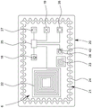
FIG. 2 is a schematic view of a patch according to the present invention;
figure 3 is a schematic cross-sectional view of the patch according to the cutting line III-III of figure 2;
FIG. 4 is a schematic diagram of an attachment according to the present invention; and
fig. 5 is a schematic flow diagram of an exemplary method according to the present invention.
In fig. 1, a system 1 for detecting a respiratory state according to the present invention is schematically depicted.
The system 1 includes a flexible patch 2. The patch 2 is configured to be attached or affixed to the skin 3 of a body 4 of a patient, in particular a human or an animal.
In the embodiment shown in fig. 1, the patch 2 is arranged or arranged in an area or region of a respiratory tract 5 of the body 4 such that activity within the respiratory tract 5 or respiratory tract related activity may act on the patch 2. In particular, the patch 2 is adapted to, arranged on or arrangeable on the skin 3, facing away from the respiratory tract 5 with reference to the skin 3 or facing in the opposite direction to the respiratory tract.
The system 1 comprises at least one sensor arrangement 6 for sensing chest activity or physical activity preferably related to the breathing state as defined in the introductory part of the description.
Preferably, the patch 2 comprises the sensor arrangement 6 or a part thereof. In particular, the sensor arrangement 6 is configured to sense chest or body activity when the patch 2 is attached or arranged at the skin 3.
The sensor arrangement 6 is preferably configured to determine and/or output a sensor signal 7 corresponding to the physical activity.
Preferably, the sensor arrangement 6 is configured to sense physical activity dependent on the respiratory state and/or the respiratory airflow 8 within the respiratory tract 5.
According to an aspect of the invention, the system 1 is configured to determine, in particular calculate, a respiratory airflow index 9 based on the sensor signal 7. In other words, the sensor signal 7 in the system 1 of the invention is used to determine or calculate the respiratory airflow index 9.
With regard to the meaning of the term "respiratory airflow index 9", reference is made to the introductory part of the description. In particular, the respiratory airflow index 9 is or comprises one or more traces, vectors, functions or different data corresponding to chest or body activity that depends on the respiratory airflow 8 and thus preferably indicates the respiratory state.
The sensor signal 7 is preferably mathematically convertible into a respiratory airflow index 9. In particular, it is preferred that the sensor signal 7 comprises or consists of data sensed by means of the sensor arrangement 6, wherein the data preferably corresponds to the respiratory gas flow 8 or the influence caused by the respiratory gas flow 8 when moving in the respiratory tract 5. That is, the sensor arrangement 6 is preferably adapted to measure or measure the influence caused by the respiratory airflow 8 within the respiratory tract 5. The respiratory airflow indicator 9 determined or calculated on the basis of the sensor signal 7 therefore preferably corresponds to the influence that the respiratory airflow 8 has within the respiratory tract 5. This enables the detection of the state of the respiratory tract 5 (also called respiratory state), in particular by a medical professional or automatically (assisted).
In the following paragraphs, the sensor arrangement 6, or parts thereof, preferably comprised in the patch 2, is described in more detail.
The sensor arrangement 6 preferably comprises at least a stretch sensor 10 configured for sensing a stretch, in particular a degree of stretch, of the skin 3. The stretch sensor 10 is preferably arranged on, in or beside the patch 2. Due to the flexibility of the patch 2, the stretch sensor 10 may be stretched by the patch 2 when the skin 3 is stretched during respiratory activity.
The detected degree of stretching preferably corresponds to the degree to which the skin 3 is stretched. If the patch 2 is suitably attached to the skin 3 in the chest area of the respiratory tract 5 or in the respiratory tract area, i.e. on the breasts of the body 4, the stretching of the skin 3 is associated with the respiratory movement and thus with the respiratory airflow 8, and its effect on the respiratory tract 5 can be detected by the stretch sensor 10. Thus, the stretch sensor 10 is configured to measure the stretch of the skin 3, which depends on the respiratory activity, the respiratory airflow 8, or its effect on the respiratory tract 5.
The sensor signal 7 preferably represents the degree of stretching. The sensor signal 7 thus enables a respiratory airflow index 9 to be determined based on information about the respiratory tract 5 and the respiratory airflow 8 on which the stretching or the degree of stretching depends.
In particular, the skin 3 is stretched to different degrees by inhalation and exhalation. The deeper the breath, the greater the difference in stretch that can be measured. Furthermore, spasms associated with the respiratory tract 5 can affect stretch, particularly the maximum measurable change in stretch or the stretch amplitude. This can be used to determine the respiratory airflow index 9.
Alternatively or additionally, the stretch sensor 10 and/or the analysis of the sensor signal 7 corresponding to or including the measurement from the stretch sensor 10 may distinguish between different stretch positions and/or different stretch directions.
Fig. 2 shows an enlarged top view of the patch 2. The stretch sensor 10 may comprise one or more strain sensor elements 10A, 10B. In the embodiment shown, the strain sensor element 10A has a different orientation compared to a different strain sensor element 10B. In particular, the strain sensor elements have an orientation at least substantially perpendicular to each other. The strain sensor elements 10A, 10B are preferably long, in particular (each) forming a strain sensor strip. However, different embodiments are possible and are also the focus of the present invention.
By means of the stretch sensor 10, longitudinal stretching of the chest area of the body 4 and longitudinal stretching along the perimeter of the body 4 may be used alone or in combination for further interpretation. This may be used to determine or improve the respiratory airflow index 9. This may improve the determination of the respiratory airflow index 9 and thus may improve the determination of the respiratory state that can be found on the basis of the respiratory airflow index 9.
Returning to fig. 1, the system 1 or the sensor arrangement 6 optionally comprises one or more additional sensors. The sensor arrangement 6, in particular the patch 2, preferably comprises a temperature sensor 11 by means of which the temperature of the skin 3 and/or the temperature of the environment can be measured.
Alternatively or additionally, the system 1, the patch 2 and/or the sensor arrangement 6 comprises an ECG sensor 12 and/or an EMG sensor 13 for measuring a cardiac activity signal and/or a muscle activity signal, respectively.
In particular, the EMG sensor 13 may be used to detect muscle activity occurring during breathing and/or muscle activity of the respiratory tract 5 or respiratory tract dependent muscle activity in order to facilitate or improve the determination or calculation of the respiratory airflow index 9.
The temperature sensor 11 may also be used to improve the result of the determination of the respiratory airflow index 9. In particular, the temperature measured by the temperature sensor 11, which is preferably arranged on the patch 2, may be used to ensure that the patch 2 is properly attached or adhered to the skin 3. For example, measuring a temperature different from the expected body surface temperature may be used as an indicator that the patch 2 is not properly attached to the skin 3. Therefore, the temperature sensor 11 can be used to detect a process error, for error processing, or the like.
The ECG sensor 12 and/or the EMG sensor 13 and/or the temperature sensor 11 are preferably arranged on or form part of the patch 2 such that it is directly influenced or affected by, can be influenced by or can be affected by (chest) physical activity, such as strain caused by stretching of the skin 3.
The patch 2 preferably further comprises a patch interface 14 for receiving and/or transmitting energy and/or information, such as the sensor signal 7, a part thereof, or other/further data.
The patch interface 14 in the illustrated embodiment includes a power coupling device 15, a data coupling device 16, and/or an antenna 17.
The power coupling device 15 is preferably configured for inductive power transfer and/or near-field power transfer. Particularly preferably, the power coupling device 15 is configured for wireless energy transfer. Here, the power coupling device 15 comprises or is formed by a coil, which may be used for inductive energy transfer. Additionally or alternatively, the power coupling device 15 may comprise different means for power transfer, such as galvanic contacts, or means for capacitive energy transfer, such as capacitor plates (not shown).
The data coupling device 16 may be a separate part of the power coupling device 15 or may be part of the power coupling device 15, while the power coupling device 15 may also be used for data coupling. In the embodiment shown in fig. 1 to 3, the data coupling device 16 is formed by or comprises a high-frequency coil. The high frequency coil may alternatively be used to form a resonant circuit for operating one or more of the sensors or the transmitter or receiver or transceiver of the patch 2 and/or for data transfer and/or energy transfer.
The antenna 17 is preferably configured for wireless transmission of the sensor signal 7. Alternatively or additionally, further sensor information, status information about the operation of the patch 2 or parts thereof may be communicated by means of the antenna 17. However, such data transfer may alternatively or additionally be supported by the patch 2 in a different (wireless) manner, e.g. by inductive coupling, e.g. by the power coupling device 15 or the data coupling device 16, or by galvanic contacts (not shown).
Wireless interfaces such as wireless power coupling device 15, and/or wireless data coupling device 16, and/or wireless antenna 17 are preferred because avoiding galvanic contact may improve reliability and ease of use, especially in view of the field of application of patch 2.
The patch 2 may also have transistors and active or passive electronic components for supporting detection processes, energy transfer, energy (intermediate) storage, not shown in detail. However, such devices and circuits are well known in the art (e.g., from sensor data sheets).
Figure 3 shows a schematic cross-sectional view of the patch 2 according to the cutting line III-III of figure 2.
The patch 2 preferably comprises a plurality of layers 2A, 2B. The carrier layer 2A of the patch 2 may cover or carry most of the electronic or sensor elements of the patch 2. In particular, the stretch sensor 10, the temperature sensor 11, the EMG sensor 13, the patch interface 14, the power coupling device 15, the data coupling device 16, and/or the antenna 17 may be arranged on and/or in the carrier layer 2A, preferably covered or enclosed in a watertight manner.
Furthermore, the patch 2 preferably comprises an adhesive layer 2B configured to attach or adhere the patch 2 to the skin 3. This adhesive layer 2B may preferably cover completely or at least substantially or partially one side of the carrier layer 2A, in particular at least in the peripheral region along the (entire) edge of the patch 2 or the carrier layer 2A.
The adhesive layer 2B preferably overlaps at least the stretch sensor 10. This improves the coupling of the stretch sensor 10 to the skin 3. Therefore, the accuracy of the stretch sensor 10 and the accuracy of the respiratory airflow index 9 calculated based on the measurement result from the stretch sensor 10 can be improved.
The patch 2 may comprise electrodes 12A, preferably for or of an ECG sensor 12, which may be arranged at or inside the surface of the adhesive layer 2B, such that one or more of the electrodes 12A can make galvanic contact with the skin 3. Therefore, the adhesion layer 2B preferably does not cover the electrode 12A. Alternatively, the adhesive layer 2B is (at least partially) conductive as long as it covers the electrode 12A or forms the electrode 12A.
The patch 2 may comprise one or more (preferably flexible) circuit boards 2C or printed circuit boards for connecting or interconnecting the sensors and further components of the patch 2.
The circuit board 2C may be arranged inside the carrier layer 2A or on the carrier layer. The circuit board 2C may be flexible and/or include conductors for connecting one or more of the sensors and/or components of the patch 2, such as the patch interface 14, the power coupling device 15, the data coupling device 16, and/or the antenna 17. The circuit board 2C may be a printed circuit board and/or a laminated circuit board.
The sensor arrangement 6 preferably comprises an acoustic wave sensor 18. Acoustic wave sensor 18 is configured to detect sounds or vibrations caused by respiratory airflow 8, activity of respiratory tract 5, and/or sounds or vibrations caused by respiratory airflow 8 acting on or interacting with respiratory tract 5.
The acoustic wave sensor 18 may include and/or be formed from a microphone and/or a structural acoustic sensor. Detecting structural sounds is particularly preferred, as this is a simple and reliable means for collecting data that is correlated with the respiratory airflow index 9 and allows the respiratory airflow index to be determined, calculated and/or improved.
Alternatively or additionally, the sensor arrangement 6 comprises a motion sensor 19 for detecting a motion of the body 4, in particular a motion of the skin 3 of the body. The motion sensor 19 may be adapted to sense motion such as rib cage or chest rise and fall caused by respiratory activity.
The motion sensor 19 may be used to detect the breathing frequency and breathing phase. This enables or simplifies the interpretation of the further sensor information and the life state of the body 4.
The motion sensor 19 may also be used to measure pulse. Alternatively or additionally, the sensor arrangement 6 may comprise a separate pulse sensor, or different ones of the sensors of the sensor arrangement 6 may be used for sensing the pulse of a nearby artery.
The sensor signal 7 preferably comprises or communicates data or measurements from the sensor arrangement 6, in particular from one or more of a stretch sensor 10, a temperature sensor 11, an ECG sensor 12, an EMG sensor 13, a sound wave sensor 18, and/or a motion sensor 19. In this respect, it is preferred that the sensor signal 7 represents the degree of stretching, the temperature, the ECG value, the EMG value, the sound caused by the breathing gas flow 8, and/or the movement of the body 4.
The system 1 is preferably configured to determine or calculate a respiratory airflow index 9 by analyzing preferably chest stretch, temperature, ECG values, EMG values, sound, and/or motion.
According to a further aspect of the invention, which can also be implemented independently, the system 1 preferably comprises at least two parts which are connectable to each other and/or separable from each other.
The system preferably includes an add-on device 20. The attachment 20 is attachable to and detachable from the patch 2. Thus, patch 2 may include an additional device 20 that may be removable and/or reattachable. In particular, the additional device 20 may be or form a layer of the patch 2 when the system 1 is ready for use.
In fig. 4, a top view of the add-on device 20 is depicted. The add-on device 20 need not be flexible, it may be (at least substantially) rigid or dimensionally stable. The add-on device 20 may comprise a circuit board, preferably a printed circuit board, on which contacts may be connected to and/or formed by components of the add-on device 20, as in the present case where the coil forms the power coupling device 22 of the add-on device 20.
The add-on device 20 may be reusable, while the patch 2 for direct contact with the skin 3 is preferably a disposable device which is used only once for hygienic reasons.
The supplemental device 20 is preferably configured to provide energy to the patch 2. Alternatively or additionally, the additional device 20 is configured to receive the sensor signal 7, which comes completely or partially from the patch 2.
The supplemental device 20 is preferably reusable. For this purpose, the additional device 20 may preferably be attached and/or coupled to the plurality of patches 2 continuously.
The system 1 is preferably configured such that if or by attaching the add-on device 20 to the patch 2 or connecting or mounting the add-on device 20 on the patch 2, a mechanical, electrical and/or data connection can be established between the add-on device 20 and the patch 2. It is particularly preferred that this connection is established (automatically) when the add-on device 20 is connected or mounted on the patch 2. Alternatively or additionally, the connection is preferably (automatically) broken when the additional device 20 is detached or removed from the patch 2. This contributes to a very easy handling.
Preferably, the additional device 20 is patch-like and/or formed as a flexible patch. In particular, the add-on device 20 may comprise a preferably flexible carrier layer and/or an adhesive layer, while its components are located on or embedded in the carrier layer.
Preferably, the additional device 20 is at least substantially adapted or formed to resemble the patch 2. The additional device 20 preferably has the same or similar dimensions as the patch 2. The components of the add-on device 20 are preferably arranged in a similar or corresponding manner to the arrangement of the components on the patch 2. It is particularly preferred that components of the additional device 20 that are identical or similar or correspond to components of the patch 2, such as the power coupling device 22, are located at least substantially in a similar location to corresponding components on the patch 2.
The system 1 is preferably a multipart modular system 1, while the patch 2 forms a first module and the add-on device 20 forms a second module, the modules being configured to be combined to form the functional system 1 or a part thereof. Thus, the patch 2 may comprise at least two parts, i.e. on the one hand the carrier layer 2A and/or the adhesive layer 2B, and on the other hand the additional device 20. Together, these two parts form the patch 2, the system 1 or a part of the system 1. These parts together preferably comprise a sensor arrangement 6. The sensor arrangement 6 may comprise or be formed by parts of both the patch 2 and the further device 20.
The sensor arrangement 6 is preferably provided on or covering both the patch 2 and the further device 20. This allows for re-use of the sensors and further components of the system 1 which do not need to be in direct contact with or close to the skin 3, the body 4 or affected thereby and may thus form part of the additional device 20.
Preferably, at least the acoustic sensor 18 and/or the motion sensor 19 are arranged on the additional device 20 instead of on the patch 2.
In fig. 1, the additional device 20 is shown being moved away from the patch 2. However, during operation, it is preferred that the additional device 20 is attached to the patch 2 such that the additional device 20 covers or overlaps the patch 2.
The add-on device 20 and patch 2 are preferably configured to be connected. In particular, the add-on device 20 has connection means to attach it to the patch 2, such as glue, an adhesive film, a tape, or other means for preferably removably holding the add-on device 20 at and/or on the patch 2.
The further device 20 together with the patch 2 preferably forms a piggyback configuration, wherein the patch 2 is connected or connectable to the skin 3, and wherein the further device 20 is connected or connectable to the patch 2 at a side of the patch 2 facing away from the skin 3 or from the side of the patch 2 arranged to be attached to the skin 3.
The add-on device 20 in the illustrated embodiment includes an add-on device interface 21 configured to electrically and/or electronically connect the add-on device 20 to the patch 2. The add-on device 20, and in particular the add-on device interface 21, may include a power coupling device 22, a data coupling device 23, and/or an antenna 24.
The power coupling device 22 of the add-on device 20 preferably corresponds to the power coupling device 15 of the patch 2. The power coupling devices 15, 22 may be configured and arranged in a manner to enable power coupling from the add-on device 20 to the patch 2. In particular, both power coupling devices 15, 22 operate inductively, comprise or are formed by one or more coils, and/or comprise capacitive coupling means such as one or more capacitive plates or different means for energy transfer.
Thus, arranging the power coupling devices 15, 22 adjacent to or overlapping each other establishes a power transfer connection that allows power, in particular current, to be transferred between the add-on device 20 and the patch 2. Thus, the add-on device 20 is preferably configured to provide electrical energy to the patch 2, particularly preferably wirelessly or without contact. Alternatively or additionally, galvanic contacts may be provided, or the power coupling device 15, 22 may also comprise or be realized by contacts, in order to establish an electrical connection between the patch 2 and the additional device 20.
Alternatively or additionally, the additional device 20 is configured to receive the sensor signal 7 or part thereof from the patch 2, preferably in a wireless manner. This may be achieved using the data coupling device 23 of the add-on device 20, which preferably corresponds to the power coupling device 16 of the patch 2.
The data coupling devices 16, 23 may be coupled and used to establish data connections by being arranged close to each other. In the embodiment depicted in FIG. 1, the data coupling devices 16, 23 operate inductively or are implemented by coils. Alternatively or additionally, capacitive coupling or differential coupling may be achieved by the data coupling devices 16, 23.
The data coupling device 16, 23 is preferably configured to enable the transfer of data, in particular the sensor signal 7 or a part of the sensor signal 7. Thus, the sensor signal 7 or a component thereof may be transmitted from the patch 2 to the further device 20. Thus, the measurement data obtained by the stretch sensor 10 and optionally the measurement data from the temperature sensor 11, the ECG sensor 12, the EMG sensor 13, and/or further sensors possibly included in or implemented by the patch 2 may be forwarded to the additional device 20.
In an alternative configuration, the power coupling devices 15, 22 may be used for data transfer. In yet another alternative, the antenna 24 of the additional device 20 may be used for data transfer between the patch 2 and the additional device 20. However, it is preferred that the antenna 17 of the patch 2 or the antenna 24 of the additional device 20 may be used to forward the sensor signal 7, the respiratory airflow index 9 or further information to a remote device. It is therefore not mandatory that both the patch 2 and the additional device 20 have antennas 17, 24. It may be sufficient that only one of them has an antenna 17, 24.
The power coupling devices 15, 22 and/or the data coupling devices 16, 23 are preferably configured to be arranged (completely) overlapping in order to facilitate a high coupling factor. In particular, the power coupling devices 15, 22 are similar in size and/or configuration. Alternatively or additionally, the data coupling devices 16, 23 are similar in size and/or configuration.
Furthermore, it is preferred that the additional device 20 may be placed on the patch 2 such that the power coupling devices 15, 22 overlap, preferably in such a way that the focal point or center of the respective power coupling device 15, 22 is arranged on or cut by an axis which is at least substantially perpendicular to both power coupling devices 15, 22.
Thus, if the power coupling devices 15, 22 are coils, as in the illustrated embodiment, the coils are similar, positioned adjacent to each other, and/or positioned in at least substantially parallel planes, surfaces, or layers to enable coupling therebetween. The same preferably applies to the data coupling devices 16, 23.
In another alternative, the sensor signal 7 or a component thereof is transmitted or transmittable to the patch 2, and the patch 2 may transmit the sensor signal 7 to a remote device, preferably using the antenna 17.
The sensor signal 7 transmitted to the remote device may include measurements from both the add-on device 20 and the patch 2.
Conductors such as wires on the patch 2 used to connect or interconnect components such as the stretch sensor 10, the temperature sensor 11, the ECG sensor 12, the EMG sensor 13, the patch interface 14, the power coupling device 15, the data coupling device 16, and/or the antenna 17 are preferably meandering, follow an undulating path, and/or are more generally configured to reversibly deform or stretch, thereby allowing the patch 2 to be stretched while avoiding damage to the conductors or wires.
In the illustrated embodiment, the conductive wire forming the antenna 17 has a structure that allows reversible stretching without damage. Additional conductors (not shown), such as conductors forming coils of the power coupling device 15 or the data coupling device 16, may be constructed accordingly.
Preferably, the structure of the conductor allows at least about 20%, preferably 30%, of the patch 2 to be stretched without affecting the integrity of the conductor. Preferably, sufficient excess length of conductor wire is provided to enable the patch 2 to be stretched without affecting the conductor wire. In particular, the distance bridged by a plurality (preferably more than five) meanders, periods, waves or different (repeating) structures to allow stretching is preferably less than 80%, 70% or 60% of the track length of the conductor wire.
The conductor lines used in the additional device 20 do not necessarily have to be formed as corrugated tracks as well. However, this is possible and may enhance the coupling factor reasonably. However, the conductor lines used in the additional device 20 may be at least substantially straight to avoid potential negative effects or increase production labor. In particular, wires that are not part of power coupling device 22, data coupling device 23, and/or antenna 24 should be at least substantially straight.
The additional device interface 21 is preferably configured for transmitting and/or receiving the sensor signal 7, and/or the respiratory airflow index 9. In particular, the add-on device 20 is adapted to transmit the sensor signal 7 and/or the respiratory airflow index 9 to a remote device via an add-on device interface 21.
Alternatively or additionally, an alert 41 and/or instruction 42 may be transmitted or sent. In this respect, it is preferred that the add-on device 20 or the add-on device interface 21 is configured for wirelessly transmitting and/or receiving the alert 41 and/or the instruction 42. However, alternatively or additionally, different schemes are possible.
The further device 20 preferably comprises further components for controlling, detecting, determining, and/or calculating the respiratory airflow index 9.
In another aspect of the invention, the system 1, preferably the add-on device 20, comprises a processing device 26 configured to analyze the sensor signal 7. In the illustrated embodiment, the processing device 26 forms part of the supplemental device 20. However, alternatively or additionally, the processing device 26 may also be arranged on or form part of the patch 2 or a different device of the system 1.
The add-on device 20 preferably comprises a memory 28 for storing or intermediately storing the sensor signal 7, parts thereof or corresponding data.
Alternatively or additionally, the additional device 20 may be configured to store the respiratory airflow indicator 9 in the memory 28 after the respiratory airflow indicator 9 has been calculated from the sensor signal 7, preferably by means of the processing device 26.
However, after calculating the respiratory airflow index 9 based on the sensor signal 7, it is not necessary to store the respiratory airflow index compulsorily. For example, it may be directly forwarded or transmitted, etc. Alternatively or additionally, the respiratory airflow index 9 may be used directly to determine different metrics corresponding to the respiratory state or to determine the respiratory state.
For calculating, by the processing device 26, the respiratory flow index 9 based on the sensor signal 7, the sensor signal 7 may be associated with one or more reference signals 43 or values that may be stored in the memory 28. Alternatively, the additional device 20 may forward the sensor signal 7 and the calculation of the respiratory airflow index 9 is performed externally.
In another aspect of the invention, the processing device 26 is configured for determining or calculating a respiratory airflow limitation indicator 40 or individual irregularities related to the respiratory tract 5 based on the respiratory airflow indicator 9 or the sensor signal 7. This may enable deeper analysis by the user or guide the user to diagnose or treat without or with automatically provided diagnostic or treatment instructions. If the respiratory airflow limitation indicator 40 is detected or exceeds a threshold, the processing device 26 may be configured to generate an alert 41 and/or instructions 42.
The further device 20 preferably has a control device 25 for controlling the functions of the further device 20 and/or the functions of the patch 2. In particular, the control device 25 is configured for controlling the energy transfer to the patch 2. In this regard, the control device 25 may receive energy from an energy storage device 27, which may be included in or on the additional device 20. Energy from the energy storage device 27 may be forwarded to the patch 2 via the power coupling device 15, 22.
Preferably, the control device 25 generates an alternating current which is supplied to the power coupling device 22 of the add-on device 20. With this alternating current, the power coupling device 22 may generate an alternating electric, magnetic, or electromagnetic field. In the illustrated embodiment, the alternating magnetic field is generated by an alternating current flowing through the coil windings. This alternating field in the power coupling device 15 of the patch 2 induces or generates a current or voltage that can be used as a source for the stretch sensor 10 and/or another device of the patch 2.
The control device 25 may alternatively or additionally control the sensors of the add-on device 20 and/or the sensors of the patch 2 to measure and/or transmit the measurement results, preferably forming the sensor signal 7 or a part thereof.
The sensor signal 7 may comprise measurements from the various sensors, but need not cover or take into account each of them. The sensor signal 7 may have multiple portions, components or may be different at different locations. In particular, the sensor signal 7 transmitted or transmittable from the patch 2 to the additional device 20 may cover measurement results from sensors comprised in or on the patch 2, while optionally the sensor signal 7 as provided or transmitted by the additional device 20 may additionally cover sensor results of sensors comprised in or on the additional device 20.
In another aspect of the invention, the system 1 comprises at least one user equipment 29, which may implement or form an external device, and/or may be implemented or formed by or comprise: a smartphone, tablet, laptop or a different (preferably mobile and/or wirelessly connectable) device. The user device 29 preferably comprises a user device interface 30 for communicating with the patch 2 and/or the additional device 20. The user device 29 preferably includes a user interface 31, such as a display 32 and/or control elements 33, which may be part of or provided in addition to an input device 34.
Preferably, the sensor signal 7, the respiratory airflow indicator 9, or further information derivable from the sensor signal 7 and/or the respiratory airflow indicator 9 is preferably wirelessly transmitted or transmittable to the user device 29.
The user device 29 may output at least the respiratory airflow index 9 using the user interface 31.
Alternatively or additionally, user device 29, via user interface 31, may output instantaneous respiratory airflow 35 (which is the amount of airflow that flows to respiratory tract 5 over time).
Alternatively or additionally, the user interface 31 may output a respiratory airflow rate 36 (which is the airflow over time, which may be shown in the figure as a function of volume, preferably lung volume or respiratory volume 39, in particular forming a so-called flow-volume loop).
Alternatively or additionally, a warning 41 or instructions 42 may be output. An alert 41 or instruction 42 may be calculated based on the respiratory airflow index 9.
Hereinafter, respiratory airflow index 9, instantaneous respiratory airflow 35, respiratory airflow rate 36, inhalation time 37, exhalation time 38, respiratory volume 39, alert 41, and/or instructions 42 are referred to as analysis results. Thus, such analysis results may preferably be provided to a user like a medical professional via the user device 29.
The user device 29 is preferably configured to calculate or it calculates (from the sensor signal 7 and/or the respiratory airflow index 9 provided by the add-on device 20 and/or the patch 2) such one or more analysis results.
Alternatively or additionally, the processing device 26 (which is preferably part of the additional device 20 but may also be part of the patch 2) may at least partly calculate and/or provide the analysis results. The analysis may then be done by the user device 29 and output by the user interface 31.
The respiratory airflow index 9 may alternatively or additionally be achieved by one or more of the analysis results. Accordingly, the respiratory airflow index 9 may be or correspond to at least one or more of the following: instantaneous respiratory airflow 35, respiratory airflow rate 36, inspiration time 37, expiration time 38, and respiratory volume 39.
The system 1 may be configured to automatically provide and/or automatically adapt therapeutic measures for treating a flow limitation or individual irregularity detectable based on the respiratory flow indicator 9. For example, the user device 29 may comprise the inhalation device 44, or the inhalation device 44 may be implemented separately from the user device 29, although forming part of the present system 1.
Another aspect of the invention, which may also be implemented independently, relates to a method of detecting a respiratory state using the system 1 or patch 2, while the respiratory airflow index 9 is determined based on the sensor signal 7. Alternatively or additionally, the energy is provided by, and/or the sensor signal 7 is received from, a reusable add-on device 20 attachable to and detachable from the patch 2.
Fig. 5 shows a schematic flow diagram of a method according to the invention.
As depicted in fig. 5, the sensor signal 7 preferably comprises at least the measurement results from the stretch sensor 10. Additionally or alternatively, the sensor signal 7 comprises measurements from at least one or more of the following: temperature sensor 11, ECG sensor 12, EMG sensor 13, sonic sensor 18, and motion sensor 19. However, it is not excluded that more or different sensors are used and that the corresponding measurement results form part of the sensor signal 7.
The sensor signal 7 is provided to a processing device 26 which is preferably arranged on or forms part of the add-on device 20, but may also be implemented by or form part of the patch 2 or a different device such as a user device 29.
The processing device 26 preferably receives one or more reference signals or the system 1 is configured to provide one or more reference signals 43 to the processing device 26. Those reference signals 43 may be stored in the memory 28.
The one or more reference signals 43 preferably correspond to or relate to the sensor signal 7 or a part thereof. In particular, the one or more reference signals 43 may comprise one or more samples of potential sensor signal components. The one or more reference signals 43 may comprise traces, graphs, values or functions of samples related to or forming the potential sensor signal 7 or a portion of the potential sensor signal 7. Thus, the reference signal 43 may be compared or correlated with the sensor signal 7 or a part of the sensor signal 7.
In addition, the reference signal 43 may be configured to assign the sensor signal 7 or a component thereof to the respiratory airflow index 9 or a component thereof. Thus, using the reference signal 43, the sensor signal 7 may be analyzed and the respiratory airflow index 9 may be determined or calculated.
In particular, the one or more reference signals 43 may be used for comparison with the sensor signal 7 in order to assign or identify the sensor signal 7 to a particular respiratory airflow indicator 9. This can be used to calculate (preferably by correlation) a respiratory airflow index 9.
The respiratory airflow index 9 may preferably be depicted by means of a user interface 31 or a display 32 in order to facilitate analysis of the respiratory airflow index 9 by a medical professional or the like. As shown in fig. 5, one or more of the analysis results may be output.
Alternatively or additionally, inhalation device 44 may be controlled based on respiratory airflow index 9. In particular, the respiratory airflow index 9 may be used to determine a dose of a medicament and the inhalation device 44 may be controlled in accordance therewith, such that a dose may be administered to a patient whose body 4 is monitored by the system 1 according to the invention.
A particularly preferred output diagram, which shows the respiratory airflow rate 36 as a function of the respiratory volume 39, is depicted on the display 32 of fig. 5, which is also referred to as a flow-volume loop, since this output diagram shows a closed loop representing the characteristics of the respiratory airflow 8. The flow-volume loop need not be depicted, but alternatively or additionally, the corresponding data may be analyzed.
With the aid of this map or corresponding data, a gas flow limitation indicator 40 may be derived, wherein the gas flow limitation indicator 40 is preferably equal to the limited volume VFL divided by the tidal volume VT. The indicator 40 of the flow limitation may be calculated based on the indicator 9 of the respiratory airflow, in particular by a graph-based graphical analysis or based on corresponding information or data, even if the respiratory airflow rate 36 or the indicator 9 of the respiratory airflow is not depicted.
Preferably, the airflow limitation indicator 40 may be derived even if no absolute value of the respiratory airflow and/or only a relative value or relative change of the respiratory airflow is available. This is particularly true if Forced Vital Capacity (FVC) is not determined. In this case, the limited Volume (VFL) and tidal Volume (VT) are only relative values, but are not relevant when determining their ratio, so the ratio or airflow limitation indicator 40 still indicates any irregularities in the respiratory airflow.
The airflow rate limitation indicator 40 may be compared to a reference value or threshold to identify a problem. If a problem is identified or if a threshold is met or exceeded, an alert 41 and/or instruction 42 may be generated or output, preferably to visit a medical professional or to administer a medicament for treating the airflow limitation.
Although the invention has been discussed with reference to specific embodiments, the invention is not to be so limited. Furthermore, it should be emphasized that the different aspects of the invention can be combined in different ways, wherein the same or different advantages can be achieved.
In particular, it is not mandatory to implement the modular system 1 together with aspects related to the calculation of the respiratory airflow index 9. Furthermore, there are many ways to determine the respiratory airflow index 9 and therefore there is no need to incorporate aspects relating to the additional apparatus 20 to implement a particular way. However, combinations of these aspects are particularly advantageous, although these aspects already provide advantages when taken alone.
Reference numerals are as follows:
1. system 20 add-on device
2. Patch 21 add-on device interface
2B adhesive layer 23 data coupling device
24 antenna of 2C circuit board
3. Skin 25 control device
4. Body 26 treatment apparatus
5. Respiratory tract 27 energy storage device
6. Sensor arrangement 28. Memory
7. Sensor signal 29 user equipment
8. Respiratory airflow 30 user device interface
9. Respiratory airflow index 31 user interface
10. Stretch sensor 32 display
10A strain sensor element 33 control element
10B strain sensor element 34 input device
11. Temperature sensor 35 instantaneous respiratory airflow
12 ECG sensor 36 respiratory airflow rate
13 EMG sensor 38 exhalation time
14. Patch interface 39 volume of breath
15. Airflow limitation indicator for power coupling device 40
16. Data coupling device 41 alert
17. Antenna 42 commands
18. Acoustic wave sensor 43 reference signal
19. Motion sensor 44 inhalation device
Claims (38)
1. A system (1) for facilitating respiratory state detection, wherein the system (1) comprises a flexible patch (2), the patch (2) having a first side and a second side, wherein the first side is configured to be attached or attached to the skin (3) of a patient's body (4) by means of an adhesive layer (2B), wherein the patch (2) comprises a sensor arrangement (6) for sensing a body activity corresponding to a respiratory state of said patient's body (4), and wherein the sensor arrangement (6) is configured to determine and/or output a sensor signal (7) corresponding to said body (4) activity,
wherein the system (1) comprises a reusable additional device (20), the additional device (20) being attachable to the patch (2) and detachable from the patch (2),
wherein the further device (20) is connected to a second side opposite to the first side of the patch (2),
wherein the additional device (20) is formed as a further flexible patch, and
wherein the additional device (20) is adapted to provide energy to the patch (2) and to receive the sensor signal (7) or a part thereof from the patch (2).
2. A system (1) according to claim 1, characterized in that the sensor arrangement (6) comprises at least one sensor (10, 11, 12, 13).
3. The system (1) according to claim 1, characterized in that the system (1) is configured to determine a respiratory airflow indicator (9) based on the sensor signal (7).
4. A system (1) according to claim 3, characterized in that the sensor signal (7) is mathematically transformable into the respiratory airflow index (9).
5. System (1) according to claim 4, characterized in that the sensor signal (7) is mathematically transformable into a respiratory airflow rate (36) or a variation thereof.
6. The system (1) according to claim 1, characterized in that the sensor arrangement (6) comprises a stretch sensor for sensing the stretching of the skin (3).
7. The system (1) according to claim 6, wherein the sensor signal (7) is representative of a degree of stretching.
8. The system (1) according to claim 1, characterized in that the system (1) comprises an acoustic wave sensor (18) configured for detecting sounds caused by the flow of breathing gas (8); and/or a motion sensor (19) for detecting a motion of the body (4).
9. The system (1) according to claim 8, characterized in that the motion sensor is configured for detecting a motion of the skin (3) of the body (4).
10. The system (1) according to claim 8, characterized in that the sensor signal (7) represents the sound and/or the movement.
11. The system (1) according to claim 8, wherein the motion sensor is adapted to detect a motion of the skin (3) of the body (4), and wherein the sensor signal (7) is representative of the sound and/or the motion.
12. The system (1) according to claim 6, characterized in that the system (1) is configured to determine or calculate a respiratory airflow indicator (9) by analyzing the stretching of the body (4).
13. The system (1) according to claim 8, characterized in that the system (1) is configured to determine or calculate a respiratory airflow indicator (9) by analyzing the sound caused by the respiratory airflow (8) and/or the motion of the body (4).
14. System (1) according to any one of claims 1-13, characterized in that a mechanical, electrical and/or data connection between the additional device (20) and the patch (2) is established when the additional device (20) is connected to the patch (2) and is disconnected when the additional device (20) is disconnected from the patch (2).
15. The system (1) according to any one of claims 1-13, characterized in that the additional device (20) is configured to provide electrical energy to the patch (2) in a wireless manner.
16. The system (1) according to any one of claims 1-13, characterized in that the additional device (20) is configured to receive the sensor signal (7) from the patch (2) in a wireless manner.
17. The system (1) according to any one of claims 1-13, characterized in that the additional device (20) comprises an additional device interface (21) for transmitting and/or receiving the sensor signal (7), the respiratory gas flow indicator (9), the alert (41), and/or the instruction (42).
18. The system (1) according to claim 17, characterized in that the additional device interface (21) transmits and/or receives the sensor signal (7), the respiratory gas flow indicator (9), the warning (41), and/or the instruction (42) in a wireless manner.
19. The system (1) according to any one of claims 1-13, characterized in that the system (1) comprises a processing device (26) arranged and configured to calculate a respiratory airflow index (9) based on the sensor signal (7) and one or more reference signals (43) or values.
20. The system (1) according to claim 19, characterized in that the processing device is arranged and configured for calculating a respiratory airflow indicator (9) by correlating the sensor signal (7) with one or more reference signals (43) or values.
21. The system (1) according to claim 19, characterized in that the processing device (26) is configured for determining or calculating a respiratory airflow limitation, a variation thereof, or an individual irregularity based on the respiratory airflow indicator (9).
22. The system (1) according to claim 21, characterized in that the processing device (26) is further configured to generate an alert (41) and/or an instruction (42) if the respiratory gas flow limitation is detected or exceeds a threshold value.
23. System (1) according to claim 19, characterized in that the processing device (26) is arranged on or forms part of the patch (2) and/or additional device (20).
24. The system (1) according to claim 17, characterized in that the system (1) comprises at least one user device (29), wherein the sensor signal (7), the respiratory flow indicator (9), the warning (41), and/or the instruction (42) are transmittable to the user device (29); and/or wherein the user device (29) comprises a user interface (31) configured to output the respiratory airflow indicator (9), the alert (41), and/or the instruction (42) via the user interface (31).
25. The system (1) according to claim 24, characterized in that the sensor signal (7), the respiratory gas flow indicator (9), the warning (41), and/or the instruction (42) are wirelessly transmittable to the user equipment (29).
26. The system (1) according to claim 3, characterized in that the system (1) is configured to automatically provide and/or automatically adapt therapeutic measures for treating a detectable flow limitation or individual irregularity based on the respiratory flow indicator (9).
27. The system (1) according to claim 3, characterized in that the respiratory airflow index (9) is an index corresponding to at least one of and/or a variation in respiratory airflow rate (36), inspiration time (37), expiration time (38), and respiration volume (39).
28. System (1) according to any one of claims 1-13, characterized in that the additional device (20) is at least substantially adapted or formed to resemble the patch (2).
29. System (1) according to any one of claims 1-13, characterized in that the patch (2) comprises a patch interface (14) for receiving and/or transmitting energy and/or information.
30. The system (1) of claim 29, wherein the patch interface (14) is a first power coupling device (15), a first data coupling device (16) and/or a first antenna (17).
31. System (1) according to any one of claims 1-13, characterized in that the additional device (20) comprises an additional device interface (21) configured for electrically and/or electronically connecting the additional device (20) to the patch.
32. The system (1) of claim 31, wherein the additional device interface is a second power coupling device (22), a second data coupling device (23), and/or a second antenna (24).
33. The system (1) according to claim 30, characterized in that the power coupling device one (15) and/or the data coupling device one (16) are configured for inductive power transfer, capacitive power transfer and/or near-field power transfer.
34. The system (1) according to claim 32, characterized in that the second power coupling device (22) and/or the second data coupling device (23) are configured for inductive power transfer, capacitive power transfer and/or near-field power transfer.
35. A method for facilitating respiratory state detection using a patch (2), the patch (2) having a first side and a second side, wherein the first side is configured to be attached or attached to the skin (3) of a patient's body (4) by means of an adhesive layer (2B), wherein the patch (2) comprises a sensor arrangement (6) for sensing body activity corresponding to the respiratory state of said patient's body (4), and wherein the sensor arrangement (6) is configured to determine and/or output a sensor signal (7) corresponding to said body (4) activity,
using a reusable add-on device (20) attachable to and detachable from the patch (2),
wherein the further device (20) is connected to a second side opposite to the first side of the patch (2),
wherein the patch (2) is supplied with energy and the sensor signal (7) is received from the patch (2) by the further device (20).
36. The method according to claim 35, characterized in that the sensor arrangement (6) comprises at least one sensor (10, 11, 12, 13).
37. The method according to claim 35 or 36, characterized by determining a respiratory airflow index (9) based on the sensor signal (7).
38. A computer readable storage medium comprising program code means or instructions configured to, when executed, perform the method of any of claims 35-37.
Applications Claiming Priority (3)
| Application Number | Priority Date | Filing Date | Title |
|---|---|---|---|
| EP16020485 | 2016-12-08 | ||
| EP16020485.5 | 2016-12-08 | ||
| PCT/EP2017/081535 WO2018104308A1 (en) | 2016-12-08 | 2017-12-05 | System and method for facilitating detection of a respiratory status |
Publications (2)
| Publication Number | Publication Date |
|---|---|
| CN110049722A CN110049722A (en) | 2019-07-23 |
| CN110049722B true CN110049722B (en) | 2022-10-14 |
Family
ID=57538990
Family Applications (1)
| Application Number | Title | Priority Date | Filing Date |
|---|---|---|---|
| CN201780076033.6A Active CN110049722B (en) | 2016-12-08 | 2017-12-05 | Systems and methods for facilitating respiratory state detection |
Country Status (5)
| Country | Link |
|---|---|
| US (1) | US20190313949A1 (en) |
| EP (1) | EP3551075B1 (en) |
| JP (1) | JP7237833B2 (en) |
| CN (1) | CN110049722B (en) |
| WO (1) | WO2018104308A1 (en) |
Families Citing this family (3)
| Publication number | Priority date | Publication date | Assignee | Title |
|---|---|---|---|---|
| JP2021129891A (en) * | 2020-02-21 | 2021-09-09 | 住友電気工業株式会社 | Terminal device, emotion analysis device, emotion analysis system, and emotion analysis method |
| CN116870306A (en) * | 2021-03-12 | 2023-10-13 | 天津怡和嘉业医疗科技有限公司 | Respiratory control assembly and ventilation therapy apparatus |
| CN113331819B (en) * | 2021-06-01 | 2024-04-02 | 合肥工业大学 | Lung function monitoring method, system, equipment and storage medium |
Citations (2)
| Publication number | Priority date | Publication date | Assignee | Title |
|---|---|---|---|---|
| KR101475501B1 (en) * | 2014-02-11 | 2014-12-30 | 동서대학교산학협력단 | Smart eye patch for sleep apnea patients, and method for protecting sleep apnea patients using the same |
| CN106073798A (en) * | 2016-06-01 | 2016-11-09 | 北京理工大学 | Real time health based on implanted and wearable biosensor technique monitoring system |
Family Cites Families (22)
| Publication number | Priority date | Publication date | Assignee | Title |
|---|---|---|---|---|
| US4909260A (en) * | 1987-12-03 | 1990-03-20 | American Health Products, Inc. | Portable belt monitor of physiological functions and sensors therefor |
| US6019732A (en) | 1997-04-11 | 2000-02-01 | Volgyesi; George A. | Device and method for measuring tidal volume |
| US6517497B2 (en) | 2000-12-13 | 2003-02-11 | Ge Medical Systems Information Technologies, Inc. | Method and apparatus for monitoring respiration using signals from a piezoelectric sensor mounted on a substrate |
| US20070299325A1 (en) * | 2004-08-20 | 2007-12-27 | Brian Farrell | Physiological status monitoring system |
| US7513875B2 (en) | 2004-10-20 | 2009-04-07 | Deepbreeze Ltd. | Method and system for managing mechanical respiratory ventilation |
| US20090076360A1 (en) * | 2007-09-13 | 2009-03-19 | Dexcom, Inc. | Transcutaneous analyte sensor |
| BR112012003078A2 (en) * | 2009-08-17 | 2019-09-24 | Univ California | interrogable external sensor system for obtaining one or more biological characteristics of a patient's body internal tissue surface or region, method for obtaining one or more biological characteristics of a patient's internal tissue surface or region, transdermal sensor system for obtaining one or more biological characteristics of a patient's internal tissue region, method for obtaining one or more biological characteristics of a patient's internal tissue region, and interrogable sensor system for obtaining one or more biological characteristics of an internal tissue region of a patient |
| US8603007B2 (en) | 2010-06-04 | 2013-12-10 | Sharp Laboratories Of America, Inc. | Data binning method and system for estimating respiratory airflow from body sound signal |
| CN103153184B (en) | 2010-08-13 | 2016-04-27 | 呼吸运动公司 | For being carried out equipment and the method for breathing vibration supervision by respiratory capacity, motion and variational measurement |
| US9277864B2 (en) | 2012-05-24 | 2016-03-08 | Vital Connect, Inc. | Modular wearable sensor device |
| US20140094676A1 (en) | 2012-09-28 | 2014-04-03 | Cardiac Insight, Inc. | Flexible, lightweight physiological monitor |
| EP2906102B1 (en) | 2012-10-12 | 2017-09-06 | DELTA Dansk Elektronik, Lys og Akustik | A monitoring device |
| US20140121473A1 (en) * | 2012-10-31 | 2014-05-01 | Matt Banet | Vital sign monitoring system featuring electronic diaper |
| JP6316305B2 (en) * | 2012-11-01 | 2018-04-25 | ブルー スパーク テクノロジーズ,インク. | Patch for body temperature logging |
| DK2958491T3 (en) | 2013-02-20 | 2022-08-15 | Pmd Device Solutions Ltd | METHOD AND DEVICE FOR RESPIRATORY MONITORING |
| JP2016517324A (en) | 2013-03-15 | 2016-06-16 | ザンソース,リミテッド ライアビリティー カンパニーZansors LLC | Health monitoring, investigation, and anomaly detection |
| US9364155B2 (en) | 2013-09-25 | 2016-06-14 | Bardy Diagnostics, Inc. | Self-contained personal air flow sensing monitor |
| JP6455843B2 (en) * | 2013-11-01 | 2019-01-23 | メドトロニック モニタリング インコーポレイテッド | Device for monitoring and processing physiological values and method of operation thereof |
| WO2015077559A1 (en) * | 2013-11-22 | 2015-05-28 | Mc10, Inc. | Conformal sensor systems for sensing and analysis of cardiac activity |
| CN106999096B (en) | 2014-10-03 | 2021-02-05 | 海港医学中心洛杉矶生物医学研究所 | Wearable device configured to facilitate diagnosis and/or assessment of pulmonary disease and corresponding method |
| US9693689B2 (en) * | 2014-12-31 | 2017-07-04 | Blue Spark Technologies, Inc. | Body temperature logging patch |
| EP3270769A1 (en) | 2015-03-19 | 2018-01-24 | Koninklijke Philips N.V. | Wearable devices with two stage of use |
-
2017
- 2017-12-05 US US16/467,106 patent/US20190313949A1/en active Pending
- 2017-12-05 JP JP2019530488A patent/JP7237833B2/en active Active
- 2017-12-05 WO PCT/EP2017/081535 patent/WO2018104308A1/en unknown
- 2017-12-05 EP EP17816611.2A patent/EP3551075B1/en active Active
- 2017-12-05 CN CN201780076033.6A patent/CN110049722B/en active Active
Patent Citations (2)
| Publication number | Priority date | Publication date | Assignee | Title |
|---|---|---|---|---|
| KR101475501B1 (en) * | 2014-02-11 | 2014-12-30 | 동서대학교산학협력단 | Smart eye patch for sleep apnea patients, and method for protecting sleep apnea patients using the same |
| CN106073798A (en) * | 2016-06-01 | 2016-11-09 | 北京理工大学 | Real time health based on implanted and wearable biosensor technique monitoring system |
Also Published As
| Publication number | Publication date |
|---|---|
| EP3551075A1 (en) | 2019-10-16 |
| JP7237833B2 (en) | 2023-03-13 |
| WO2018104308A1 (en) | 2018-06-14 |
| EP3551075B1 (en) | 2023-06-07 |
| JP2020512040A (en) | 2020-04-23 |
| CN110049722A (en) | 2019-07-23 |
| US20190313949A1 (en) | 2019-10-17 |
Similar Documents
| Publication | Publication Date | Title |
|---|---|---|
| JP6401718B2 (en) | Method and apparatus for respiratory monitoring | |
| US6517497B2 (en) | Method and apparatus for monitoring respiration using signals from a piezoelectric sensor mounted on a substrate | |
| US11534130B2 (en) | Device, system and method for detecting a cardiac and/or respiratory disease of a subject | |
| US7828742B2 (en) | Method and system of monitoring respiratory signal by radio | |
| JP5944899B2 (en) | Device for monitoring respiratory variability by measuring respiratory volume, movement, and changes | |
| JP5405500B2 (en) | Predicting cardiac decompensation based on cardiac rhythm | |
| EP3451901B1 (en) | A method and apparatus for determining at least one of a position and an orientation of a wearable device on a subject | |
| US20090281394A1 (en) | Bio-mechanical sensor system | |
| CA3103625A1 (en) | Apparatus and method for detection of physiological events | |
| US20060270941A1 (en) | Device for measuring respiration during sleep | |
| US20120029307A1 (en) | Vital-signs monitor with spaced electrodes | |
| JP2007296266A (en) | Biosensor device | |
| CN110049722B (en) | Systems and methods for facilitating respiratory state detection | |
| US20200253578A1 (en) | Wearable respiratory behavior monitoring | |
| JP2017536896A (en) | Respiration rate monitoring with a multi-parameter algorithm in a device containing an integrated belt sensor | |
| US20150182131A1 (en) | Neonatal health care monitoring system | |
| RU2742707C1 (en) | Contactless monitoring of heart rate | |
| JP2021522966A (en) | Devices and methods for deriving respiratory rates from multiple biometric sources | |
| CN114587347B (en) | Lung function detection method, system, device, computer equipment and storage medium | |
| CN107205672B (en) | Apparatus and method for evaluating respiratory data of a monitored subject | |
| JP2022136344A5 (en) | ||
| US11832914B2 (en) | Methods and systems for patient parameter fusion and feedback | |
| CN209518869U (en) | A kind of respiratory effort identifies the sleep apnea monitoring device of equipment and its application | |
| Chyliński et al. | Design and Implementation of an Embedded System for Respiratory Rate Examinations | |
| CN109222987A (en) | A kind of respiratory effort identification equipment and its application apparatus |
Legal Events
| Date | Code | Title | Description |
|---|---|---|---|
| PB01 | Publication | ||
| PB01 | Publication | ||
| SE01 | Entry into force of request for substantive examination | ||
| SE01 | Entry into force of request for substantive examination | ||
| GR01 | Patent grant | ||
| GR01 | Patent grant |