CN110035825B - Microfluidic method for processing droplets - Google Patents
Microfluidic method for processing droplets Download PDFInfo
- Publication number
- CN110035825B CN110035825B CN201780074354.2A CN201780074354A CN110035825B CN 110035825 B CN110035825 B CN 110035825B CN 201780074354 A CN201780074354 A CN 201780074354A CN 110035825 B CN110035825 B CN 110035825B
- Authority
- CN
- China
- Prior art keywords
- trapping
- droplet
- droplets
- liquid droplet
- region
- Prior art date
- Legal status (The legal status is an assumption and is not a legal conclusion. Google has not performed a legal analysis and makes no representation as to the accuracy of the status listed.)
- Active
Links
Images


Classifications
-
- B—PERFORMING OPERATIONS; TRANSPORTING
- B01—PHYSICAL OR CHEMICAL PROCESSES OR APPARATUS IN GENERAL
- B01L—CHEMICAL OR PHYSICAL LABORATORY APPARATUS FOR GENERAL USE
- B01L3/00—Containers or dishes for laboratory use, e.g. laboratory glassware; Droppers
- B01L3/50—Containers for the purpose of retaining a material to be analysed, e.g. test tubes
- B01L3/502—Containers for the purpose of retaining a material to be analysed, e.g. test tubes with fluid transport, e.g. in multi-compartment structures
- B01L3/5027—Containers for the purpose of retaining a material to be analysed, e.g. test tubes with fluid transport, e.g. in multi-compartment structures by integrated microfluidic structures, i.e. dimensions of channels and chambers are such that surface tension forces are important, e.g. lab-on-a-chip
- B01L3/502761—Containers for the purpose of retaining a material to be analysed, e.g. test tubes with fluid transport, e.g. in multi-compartment structures by integrated microfluidic structures, i.e. dimensions of channels and chambers are such that surface tension forces are important, e.g. lab-on-a-chip specially adapted for handling suspended solids or molecules independently from the bulk fluid flow, e.g. for trapping or sorting beads, for physically stretching molecules
-
- B—PERFORMING OPERATIONS; TRANSPORTING
- B01—PHYSICAL OR CHEMICAL PROCESSES OR APPARATUS IN GENERAL
- B01F—MIXING, e.g. DISSOLVING, EMULSIFYING OR DISPERSING
- B01F33/00—Other mixers; Mixing plants; Combinations of mixers
- B01F33/30—Micromixers
- B01F33/302—Micromixers the materials to be mixed flowing in the form of droplets
- B01F33/3021—Micromixers the materials to be mixed flowing in the form of droplets the components to be mixed being combined in a single independent droplet, e.g. these droplets being divided by a non-miscible fluid or consisting of independent droplets
-
- B—PERFORMING OPERATIONS; TRANSPORTING
- B01—PHYSICAL OR CHEMICAL PROCESSES OR APPARATUS IN GENERAL
- B01F—MIXING, e.g. DISSOLVING, EMULSIFYING OR DISPERSING
- B01F33/00—Other mixers; Mixing plants; Combinations of mixers
- B01F33/30—Micromixers
- B01F33/3035—Micromixers using surface tension to mix, move or hold the fluids
-
- B—PERFORMING OPERATIONS; TRANSPORTING
- B01—PHYSICAL OR CHEMICAL PROCESSES OR APPARATUS IN GENERAL
- B01L—CHEMICAL OR PHYSICAL LABORATORY APPARATUS FOR GENERAL USE
- B01L3/00—Containers or dishes for laboratory use, e.g. laboratory glassware; Droppers
- B01L3/50—Containers for the purpose of retaining a material to be analysed, e.g. test tubes
- B01L3/502—Containers for the purpose of retaining a material to be analysed, e.g. test tubes with fluid transport, e.g. in multi-compartment structures
- B01L3/5027—Containers for the purpose of retaining a material to be analysed, e.g. test tubes with fluid transport, e.g. in multi-compartment structures by integrated microfluidic structures, i.e. dimensions of channels and chambers are such that surface tension forces are important, e.g. lab-on-a-chip
- B01L3/502769—Containers for the purpose of retaining a material to be analysed, e.g. test tubes with fluid transport, e.g. in multi-compartment structures by integrated microfluidic structures, i.e. dimensions of channels and chambers are such that surface tension forces are important, e.g. lab-on-a-chip characterised by multiphase flow arrangements
- B01L3/502784—Containers for the purpose of retaining a material to be analysed, e.g. test tubes with fluid transport, e.g. in multi-compartment structures by integrated microfluidic structures, i.e. dimensions of channels and chambers are such that surface tension forces are important, e.g. lab-on-a-chip characterised by multiphase flow arrangements specially adapted for droplet or plug flow, e.g. digital microfluidics
-
- B—PERFORMING OPERATIONS; TRANSPORTING
- B01—PHYSICAL OR CHEMICAL PROCESSES OR APPARATUS IN GENERAL
- B01L—CHEMICAL OR PHYSICAL LABORATORY APPARATUS FOR GENERAL USE
- B01L2200/00—Solutions for specific problems relating to chemical or physical laboratory apparatus
- B01L2200/06—Fluid handling related problems
- B01L2200/0647—Handling flowable solids, e.g. microscopic beads, cells, particles
- B01L2200/0668—Trapping microscopic beads
-
- B—PERFORMING OPERATIONS; TRANSPORTING
- B01—PHYSICAL OR CHEMICAL PROCESSES OR APPARATUS IN GENERAL
- B01L—CHEMICAL OR PHYSICAL LABORATORY APPARATUS FOR GENERAL USE
- B01L2200/00—Solutions for specific problems relating to chemical or physical laboratory apparatus
- B01L2200/06—Fluid handling related problems
- B01L2200/0673—Handling of plugs of fluid surrounded by immiscible fluid
-
- B—PERFORMING OPERATIONS; TRANSPORTING
- B01—PHYSICAL OR CHEMICAL PROCESSES OR APPARATUS IN GENERAL
- B01L—CHEMICAL OR PHYSICAL LABORATORY APPARATUS FOR GENERAL USE
- B01L2300/00—Additional constructional details
- B01L2300/08—Geometry, shape and general structure
- B01L2300/0893—Geometry, shape and general structure having a very large number of wells, microfabricated wells
-
- B—PERFORMING OPERATIONS; TRANSPORTING
- B01—PHYSICAL OR CHEMICAL PROCESSES OR APPARATUS IN GENERAL
- B01L—CHEMICAL OR PHYSICAL LABORATORY APPARATUS FOR GENERAL USE
- B01L2400/00—Moving or stopping fluids
- B01L2400/06—Valves, specific forms thereof
- B01L2400/0688—Valves, specific forms thereof surface tension valves, capillary stop, capillary break
Abstract
Method for processing at least one first droplet (20) and at least one second droplet (25) in a microfluidic system comprising a capillary trap with a first trapping region (15) and a second trapping region (18), the method comprising the steps of: (i) trapping a first droplet (20) in a first trapping region (15), and (ii) trapping a second droplet (25) in a second trapping region (18), the first trapping region (15) and the second trapping region being arranged such that the first droplet (20) and the second droplet (25) are in contact with each other, the first trapping region (15) and the second trapping region (18) being adapted such that a trapping force exerted on one of said droplets (20) is different.
Description
Technical Field
The present invention relates to a microfluidic method for processing several droplets in at least one capillary trap of a microfluidic system. The invention also relates to a microfluidic device for carrying out said method.
Background
It is known from patent application FR 2950544 to trap droplets circulating in one or more microchannels having traps of approximately circular or elliptical shape, each trapping zone being dimensioned for trapping a predetermined number of droplets.
Trapping and merging droplets of approximately the same size or of different sizes in shallow traps having an approximately circular shape of a microfluidic system that is two-dimensional and has a plurality of traps is also known from: frame, c.mcdougal, p.abbyd, r.dangla, d.mcgloin and c.n.baroud, "Combining chains and anchors with laser for selecting with Selective manipulation with 2D droplet arrays," Lab Chip, volume 11, phase 24, page 4228, 12 months 2011, and j.tubes, c.l.park and p.abbyd. "Selective Fusion of adsorbed Droplets virus change in Surfactant concentration," Lab Chip, 2014. The droplets trapped in the same trap are different.
Such a trap does not allow for an accurate manipulation and/or control of the trapped droplets, in particular adapting the trap to droplets having different sizes, nor for droplets to be trapped in a spatially predetermined manner.
Fradet, p.abbyad, m.h.vos and c.n.baroud, "Parallel media of interaction mechanics using ultra low volumes," Lab Chip, volume 13, 22, 4326 and 4330, 10.2013 describe shallow traps having two identical regions of approximately circular shape which partially overlap to form a goggle shaped trap. Each of the two zones may capture one droplet. The shape of the catcher is such that two caught droplets can be kept in contact with each other in order to merge them into a single droplet. Such a trap is limited to handling two droplets of approximately the same size and is not suitable for handling a large number of droplets, which reduces the possible applications.
Furthermore, C-shaped traps for fixing and merging two droplets are known from: humbner, c.abell, w.t.s.huck, c.n.baroud and f.hollfelder, "Monitoring a Reaction at Submillisecond Resolution in Picoliter volumes", Anal chem.2011, 2 months and 15 days; 83(4): 1462-1468. The catcher is formed by a protruding bump in the stream of droplets that blocks the droplet. However, due to the shape of the catcher, the handling of the droplets is significantly limited and retaining the droplets in the catcher requires the presence of a fluid stream oriented in a precise direction.
Application WO2016/059302 describes a method for processing droplets in a microfluidic system, said method comprising the steps consisting of: trapping the droplet in a capillary trap and at least partially gelling the droplet or its environment. A capillary trap is capable of receiving several droplets at a depth that is greater than the diameter of the trapped droplets. However, depth-wise (depth-wise) manipulation of droplets, in particular of trapped droplets, is limited.
Application US 2015/0258543 proposes a method that allows different fluids to be brought into contact to obtain a reaction between them and to analyze the kinetics of this reaction. There is disclosed a microfluidic circuit capable of bringing droplets one at a time into a chamber that serves as a capillary trap. Two droplets having different volumes may be brought into contact and received in the figure-8 shaped chamber. The size of the two trapping regions corresponds to the size of the droplets to be accommodated in the trapping regions, each trapping region corresponding to a ring of 8. Between these different trapping regions there is an energy barrier related to the shape of the cavity. For example, due to the 8-shape of the chamber, droplets supplied from the right side will remain in the catch zone on the right side.
Application US 2010/0190263 describes an actuator for droplets having a hollow region separating two substrates. These substrates include electrodes for delivering droplets to the hollow region. The purpose of the actuator is to form and retain bubbles in these hollow areas.
The articles Dangla, r., Lee, S. & Baroud, c.n. tracking microfluidic drops in wells of surface energy, phys.rev.lett.107, 124501(1-4) (2011) and Yamada, a., Lee, S., baserow, P. & Baroud, c.n. tracking and release of nanoparticles in microfluidic wells. source mate 10, 26-28(2014) describe physics associated with capturing droplets subjected to a fluid flow in microchannels. The trapping force may be caused by: the shape and size of the catcher, the depth of the microchannel, the size of the droplet, and the physical and physicochemical properties (e.g., viscosity, surface tension, etc.) of the fluid present.
Thus, there is a need for a method for processing droplets that allows easy control of the captured droplets and capturing said droplets in a spatially predefined manner. There is also a need for methods that allow for sequential manipulation of droplets.
Disclosure of Invention
I.First aspect-method of operation
For this purpose, according to a first aspect of the invention, the invention proposes a method for manipulating at least one first droplet and at least one second droplet in a microfluidic system comprising a capillary trap having a first trapping region and a second trapping region, the method comprising the steps of:
(i) trapping the first droplet in the first trapping region, and
(ii) trapping the second droplet in the second trapping region,
the first and second trapping regions are arranged in such a way that: such that the first droplet and the second droplet are in contact with each other,
the first and second trapping regions are configured in such a way that: such that the trapping forces exerted by the first trapping region and the second trapping region on the same first liquid droplet or second liquid droplet are different.
"microfluidic system" means a system relating to the transport of at least one product, comprising, in at least one part of the system, a section having at least one dimension, measured in a straight line from one edge to the opposite edge, smaller than one millimeter.
"microdroplet" means a drop having a volume of less than or equal to 1. mu.l, better still less than or equal to 10 nl. The droplets may be liquid, gas or solid.
"capillary trap" refers to a spatial region of a microfluidic system that allows for the temporary or permanent immobilization of one or more droplets circulating in the microfluidic system. The capillary trap may be formed by one or more protrusions, in particular hollow protrusions, and/or by one or more local modifications of the surface in contact with the droplet, in particular one or more local modifications of the affinity of the surface to at least a part of the droplet content.
By "the trapping force exerted by the first and second trapping regions on the same first or second liquid droplet is different" is meant that if the first droplet is trapped only in the first trapping region, it will be retained in the first trapping region by capillary action with a trapping force different from that which the second trapping region itself will exert on the same first droplet. Thus, it is easier to release the first droplet from the trapping region that exerts the least trapping force. The same reasoning can be applied for the second droplet. The trapping force of the trapping region depends in particular on its shape, its surface in contact with the droplet and/or the nature (in particular the size) of the droplet to be trapped.
The fact that the capillary trap has two zones exerting different trapping forces on one of the droplets makes it possible to have the selectivity and the spatial selectivity of the trapped droplets, in particular avoiding the first droplet from occupying the second trapping zone, preventing the second droplet from being trapped in said second trapping zone. This is particularly advantageous when a plurality of first and second droplets are introduced into the microfluidic system.
The fact that the first droplet and the second droplet are in contact allows them to interact or coalesce (coalesce).
Preferably, the first droplet is captured in the first capture zone with a capture force greater than the capture force exerted on the first droplet by the second capture zone. Thus, the first droplet is preferably captured by the first capture zone.
Alternatively, the second droplet is captured in the second capture zone with a capture force that is less than the capture force exerted on the second droplet by the first capture zone. In this case, the first droplet and the second droplet are preferably introduced and captured sequentially in the microfluidic system.
Preferably, the first droplet is captured by a first capture zone in the microfluidic system before the second droplet is captured by a second capture zone in the microfluidic system. Thus, when a second droplet is introduced, it cannot occupy the first trapping region because it is already occupied by the first droplet.
An entrainment force greater than the trapping force of the second trapping region and less than or equal to the trapping force of the first trapping region may be exerted on the first droplet in step (i). For example, the shape of the second trapping region is chosen in such a way that: such that the trapping force of the second zone is less than the entrainment force. In other words, the droplets are subjected to hydrodynamic forces due to hydrodynamic entrainment, which is opposite to the trapping of the second trapping zone. The drag force exerted by the fluid transporting the droplets may depend on the size and instantaneous shape of the droplets, the physical and physicochemical properties of the fluid (viscosity, surface tension, etc.) and the flow rate. The first drop is trapped in the first trapping region only.
The entrainment force may be exerted, at least in part, by
-a directed fluid flow flowing in the microfluidic system. In particular, the droplets may be moved in the microfluidic system by a directed fluid flow, wherein the droplets are preferably immiscible, the fluid flow being in particular of a flow velocity and orientation such that the first droplet is captured only by the first capture zone. Moving the force exerted by the fluid on the first drop prevents the first drop from being trapped in the second trapping region;
gravity, the first droplet moving by its own weight along the inclined plane of the microfluidic system. Thus, the first droplet is retained or not retained in the first trapping region depending on the speed at which the first droplet reaches the first trapping region due to the slope of the microfluidic system;
the first droplet minimizes its tendency to surface tension. In particular, the microfluidic system may comprise a protrusion to move the first droplet, in particular a groove that becomes wider towards the capillary trap.
Preferably, the second droplet is subjected to an entrainment force as described in relation to the first droplet, which entrainment force is less than or equal to the trapping force of the second trapping region. Where an entrainment force is exerted on the second droplet by the directed fluid stream, the force exerted by the fluid stream on the first droplet captured in the first capture zone is preferably insufficient to dislodge the first droplet from the first capture zone.
Where the entrainment force on the second droplet is exerted by a directed fluid flow, the fluid flow may be directed in this manner: the second droplets may be captured only in a second capture zone having a specific orientation with respect to the orientation of the stream, in particular a second capture zone arranged upstream of the first capture zone with respect to the direction of the fluid stream.
The droplets are carried by the fluid stream to a plurality of catch zones, into which they are preferably introduced randomly and naturally occupy the most energetically favorable positions of the catch zones. They stay themselves in the catch zone. This random arrangement of droplets makes it possible to have a large number of captured droplets simultaneously and to improve the screening capacity.
In an embodiment, the method comprises the steps of:
trapping a first droplet in a first trapping region of the capillary trap, the trapping force F4 exerted by the first region on the first droplet being greater than the hydrodynamic drag force Ft4 exerted by the stream (i.e. the directed fluid stream transporting the droplet) on the first droplet such that said first droplet remains trapped in the first region, the drag force Ft4 being between F4 and F5, F5 representing the trapping force exerted by the second trapping region of the capillary trap on the first droplet,
-then trapping a second droplet in a second trapping region of the capillary trap, the hydrodynamic drag force Ft5 exerted on said second droplet by the flow during loading of said second droplet in the second region being between F5 and F3, preferably F3 being less than F4, F3 being the trapping force exerted on said second droplet by the second region of said capillary trap.
Micro-droplets
Preferably, the first capture zone exerts a different capture force on the first droplet than the first capture zone would exert on the second droplet, and the second capture zone exerts a different capture force on the second droplet than the second capture zone would exert on the first droplet. In practice, the trapping force also depends on the shape of the droplet to be trapped in relation to the shape of the trapping region. This facilitates sequential capture of the first droplet and the second droplet.
Preferably, the first trapping region exerts a trapping force on the first droplet that is greater than the trapping force that the first trapping region would exert on the second droplet. This makes it possible to prevent the second droplet from being displaced and displacing the first droplet.
The first droplet and the second droplet may be different, in particular have different sizes and/or have different contents, in particular the first droplet has a larger size and/or a larger volume than the second droplet. This ensures that the first trapping region exerts a greater trapping force on the first droplet than the first trapping region would exert on the second droplet; thus, there will be only one droplet in the first trapping region.
The first trapping region can trap one or more first droplets.
The second capture zone can capture one or more second droplets.
As a variant, the first and second droplets differ in at least one of their properties, in particular their viscosity and/or their interfacial tension and/or their affinity to a specific coating of at least one of the trapping regions.
Preferably, the first trapping region traps only the first droplet and/or the second trapping region traps only the second droplet. In particular:
the maximum dimension of the first droplet as viewed from above when captured may be greater than or equal to the maximum dimension of the first capture zone as viewed from above, and/or
The maximum dimension of the second droplet as viewed from above when captured may be greater than or equal to the maximum dimension of the second capture zone as viewed from above, and/or
-the first droplet, when captured, fills at least 70%, better 80%, even better 90% of the volume of the first capture zone, and/or
-the second droplet, when captured, fills at least 70%, better 80%, even better 90% of the volume of the second capture zone, and/or
-the volume of the first droplet, when captured, is greater than or equal to the volume of the first capture zone, such that the first droplet extends partially outside the first capture zone, and/or
-the volume of the second droplet, when captured, is greater than or equal to the volume of the second capture zone, such that the second droplet extends partially outside the second capture zone.
One of the first droplet or the second droplet may be an air microbubble.
A plurality of second trapping regions and/or first trapping regions
The capillary trap may comprise a plurality of second trapping regions, step (ii) consisting of: each second trapping region traps one second droplet, the first trapping region and the second trapping region being arranged in such a way that: each second droplet is in contact with at least one of the first droplet or the second droplet.
The capillary trap may comprise a plurality of first trapping regions, step (i) consisting of: each first trapping region traps one first droplet, the first trapping region and the second trapping region being arranged in such a way that: each first droplet is in contact with at least one of the second droplet or the first droplet.
Preferably, each second droplet is connected to the or each first droplet.
By "connected to" is meant that each second droplet is either in direct contact with the first droplet, or in contact with another second droplet or a series of second droplets and/or first droplets, which itself is in contact with the first droplet.
"string of droplets" refers to a plurality of droplets that contact each other, forming a straight line or a curve.
The second droplets may all be in contact with at least one first droplet captured in the capillary trap.
At least two second trapping regions may be configured such that their trapping forces exerted on one of the second liquid droplets are different. The second droplets captured by the at least two second capture zones may differ in at least one of their properties, in particular in their largest dimension.
As a variant, all second trapping regions of the capillary trap are identical.
Multiple capillary trap
The microfluidic system may comprise a plurality of capillary traps, each capillary trap comprising a first capture region and a second capture region, step (i) consisting of: (iii) trapping a first droplet in the first trapping region of each capillary trap, step (ii) consisting of: trapping a second droplet in the second trapping region of each capillary trap, the first trapping region and the second trapping region of each capillary trap of the plurality of capillary traps being arranged in such a way that: such that a first droplet and a second droplet captured in the capillary trap are in contact with each other in the capillary trap.
Each capillary trap may include one or more of the features described above.
All traps of the microfluidic system may each comprise a first and a second trapping region arranged in such a way that: such that a first droplet and a second droplet captured in the capillary trap are in contact with each other in the capillary trap.
As a variant, only some of the capillary traps of the microfluidic system each comprise a first and a second trapping region arranged in this way: such that a first droplet and a second droplet captured in the capillary trap are in contact with each other in the capillary trap.
The method may comprise the step of trapping gas microbubbles, in particular air microbubbles, in one of the first trapping region or the second trapping region. This can disable the problematic trap. In fact, the first or second droplet cannot be trapped in the problematic trapping region due to the presence of the gas microbubbles.
Directed fluid flow
Step (ii) may comprise sub-steps (ii ') and (ii "), said sub-step (ii') consisting of: (iii) trapping the second droplets in a trapping region or regions of the second trapping region under the action of the first directed fluid stream, said sub-step (ii ") consisting of: the second droplets are captured in another or some other of said second capture zones by a second directed stream of fluid, the first and second streams of fluid having different orientations.
The second droplets of steps (ii') and (ii ") may differ significantly by at least one of their properties and/or their contents. The second trapping zone of steps (ii') and (ii ") may be the same.
Thus, by selecting the orientation of the fluid stream, droplets can be selectively captured in one of the two capture zones, which allows a predefined spatial positioning of the droplets in contact with each other. The first droplet may then be contacted with a different second droplet in a controlled manner, particularly in the case of combinatorial chemistry. In the case of gel-containing droplets, the spatial arrangement of the gel droplets in the capillary trap can also be controlled so as to obtain droplets having a controlled shape and composition after fusion.
Coalescence
The method may comprise step (iii) consisting of: merging each of the second droplets or each of the second droplets captured in the or each of the second capture zones with the first droplet. This coalescence allows in particular the contents of the two droplets to mix.
The coalescence may be selective, i.e. the second droplet or droplets intended to fuse with the first droplet may be selected to be in contact with the first droplet, in particular by using an infrared laser (e.g. as described in e.fradet, p.abbyad, m.h.vos and c.n.baroud, "Parallel media measurements of reaction kinetics using ultra low volumes," Lab Chip, volume 13, phase 22, page 4326-.
As a variant, coalescence of droplets is non-selective, i.e. all second droplets of the capillary trap fuse simultaneously with the first droplets, in particular by adding a product promoting the coalescence to the environment of the capillary trap or applying an external physical stimulus (e.g. a mechanical wave, a pressure wave, a temperature change or an electric field).
Release of the second droplet
As a variant, step (iii) consists of: the or at least one second droplet captured in the second capture zone is drained out of the capillary trap. Step (iii') may consist of: applying a directed fluid stream configured for exerting an entrainment force on the one or more second droplets that is greater than the trapping force of the second trapping region, the fluid stream being configured for exerting an entrainment force on the first droplet or droplets that is less than or equal to the trapping force of the first trapping region such that the first droplet or droplets remain trapped in the first trapping region.
In this step, one or more second droplets may be drained from the second trapping region, the capillary trap being configured such that the fluid stream exerts a different entrainment force on the second trapping region due to its orientation, the method preferably comprising step (iv) consisting of: comprising changing the orientation of the fluid stream so as to eject at least one or more second droplets from at least one other trapping region. This allows for selective release of the second droplet. Thus, the first droplet and the one or more second droplets may be brought into contact with each other for a sufficient defined time such that, in particular due to the interaction between the first droplet and the second droplet or second droplet(s), the second droplet or second droplet(s) undergoes a change (e.g. a change in content) and is then released for analysis. This may also allow for changing a second droplet to another second droplet before coalescence of droplets in case of a protocol error.
Third droplet
The method may comprise a step (v) after step (iii) or (iii'), said step (v) consisting of: the third droplet is trapped in the second trapping region or regions that no longer have the second droplet, so that the first and third droplets contact each other. The third droplet may be the same or different from the second droplet. The third droplet may merge with the droplet captured in the first capture zone or be released as described above for the second droplet. Step (vi) may be repeated several times. This makes it possible, for example:
-sequentially diluting the contents of the first or second droplet,
providing additional reagents for the contents of the first droplet or droplets trapped in the first trapping region,
-several updates of the medium of one or more first droplets containing cells trapped in the first trapping region,
-supplying the drug several times at given time intervals to one or more first droplets containing the pathogen or diseased cells to evaluate its dosimetry for treatment, or
-supplying cells several times to form a micro-tissue with several cell layers.
Release of capillary traps
The method may comprise step (vi) consisting of: all droplets present in the capillary trap are emptied out of the capillary trap, in particular using a fluid flow exerting an entrainment force greater than the trapping force exerted on the droplets. Such a step may allow the droplets to be released for analysis thereof.
The method may comprise the steps of: the state of the microfluidic system is measured. The measurement may be performed before and/or after droplet fusion and/or release.
Preferably, the final droplet or final droplets(s) obtained may comprise means to identify their contents, in particular by the presence of some beads or particles, by the presence of various colors or shapes and/or by a colorimetric or fluorescent signal proportional to the initial concentration of the compound comprised by one of the first and second droplets.
The above method can be performed using a microfluidic system described below.
Additional step
The method may comprise the additional steps of:
-incubation, and/or
-observation or measurement, in particular by imaging, by colorimetric measurement, fluorescence measurement, spectroscopic measurement (UV, raman) or temperature measurement.
These steps may be performed before and/or after coalescence of the droplets.
The step of observing or measuring makes it possible to determine the content of each droplet before and/or after fusion and, for example, to determine the changes that occur after fusion.
The viewing step is particularly useful, for example, where a library of different droplets is used for forming a map of the various droplets prior to fusion.
II.Microfluidic device
The invention also relates to a microfluidic device for trapping microdroplets, in particular for carrying out the method of any one of the preceding claims, said device comprising a capillary trap having a first trapping region and a second trapping region arranged in such a way that: such that a first droplet captured in the first trapping region and a second droplet captured in the second trapping region are in contact with each other in the capillary trap, the first trapping region and the second trapping region being configured in such a way that: such that the trapping forces exerted by the first trapping region and the second trapping region on the same first liquid droplet or second liquid droplet are different.
The fact that the capillary trap has two zones exerting different trapping forces on one of the droplets makes it possible to have the selectivity of the trapped droplets and to trap the droplets in a spatially predetermined manner, in particular avoiding that the first droplets occupy the second trapping zone, thereby preventing the second droplets from being trapped in said second trapping zone. This is especially true when introducing a plurality of first and second droplets into a microfluidic system.
The fact that the first droplet and the second droplet are in contact allows them to interact or to be able to fuse easily.
Trapping region
The first trapping region and the second trapping region are preferably cavities. The use of a trapping region in the form of a chamber facilitates the handling of the droplets and in particular the trapping of the droplets and/or the release of the droplets.
The first trapping region and the second trapping region may be separate.
Alternatively, the first trapping region and the second trapping region are connected together.
Preferably, the capillary trap lacks rotational symmetry when viewed from above. This anisotropy makes it possible to trap droplets in a spatially predetermined manner.
Preferably, the first trapping region and the second trapping region are arranged side by side when viewed from above.
The first and second trapping regions are preferably different by at least one of their dimensions. In particular, the first trapping region and the second trapping region have different heights, the first trapping region being significantly higher than the second trapping region, or the first trapping region and the second trapping region have different shapes, the first trapping region having a significantly larger cross-section than the second trapping region when viewed from above. The difference in trapping force is then at least partially related to the size of the trapping region, in particular the height or the cross section as viewed from above.
By "height of the trapping region" is meant the average height of the trapping region of the microfluidic system in cross-section.
The second trapping region may become wider at least in one direction close to the first trapping region. This makes it possible to direct the second droplet in the direction of the first droplet to keep the second droplet in contact with the first droplet. In fact, in order to minimize the surface energy of the second droplet, the second droplet tends to move along the second trapping region towards a region of larger size.
The second trapping region may become wider as it approaches the first trapping region when viewed from above. Preferably, the angle of divergence α is such that the second droplet is always in contact with the two opposite walls defining it. The second trapping zone can become wider with a divergence angle alpha that is not zero, in particular from 10 deg. to 120 deg.. The second trapping region can have an approximately triangular or truncated triangular shape.
The second trapping region may have a height that increases in the direction of the first trapping region.
Preferably, the height of the second trapping region is less than or equal to the maximum dimension of the first trapping region, more preferably less than or equal to half the maximum dimension of the first trapping region. The fact that the height of the second trapping region is limited makes it possible to avoid that the flow line of the fluid is disturbed by the second trapping region to such an extent that the second droplet is prevented from being trapped.
The height of the first catch region may be such that the volume of the first catch region is greater than or equal to the volume of the first droplet. This makes it possible to have a first trapping region with a high trapping force, wherein the first droplet is slightly deformed, in particular has a concave lower interface, which may facilitate contacting of the encapsulating elements to form clusters (e.g. cell clusters) to form spheroids after sedimentation.
A plurality of second trapping regions and/or first trapping regions
The capillary trap may comprise a plurality of second trapping regions arranged in such a way: such that each captured second droplet contacts at least one of the first droplet or the second droplet captured in the capillary trap.
The capillary trap may comprise a plurality of first trapping regions arranged in such a way: such that each captured first droplet is in contact with at least one of the second droplet or the second droplet(s) or the first droplet captured in the capillary trap.
Preferably, the first and second trapping regions are arranged such that each second droplet is connected to the or each first droplet.
The first trapping region and the second trapping region may be arranged in such a manner that: such that the second droplets are all in contact with at least one first droplet captured in the capillary trap.
The at least two second trapping regions or first trapping region may be configured such that their trapping forces exerted on one of the second liquid droplets are different. The second droplets captured by the at least two second capture zones may differ in at least one of their properties, in particular in their largest dimension.
As a variant, all second trapping regions of the capillary trap are identical.
Multiple capillary trap
Preferably, the device comprises a plurality of capillary traps, each capillary trap comprising a first trap region and a second trap region, preferably arranged in such a way that: such that second droplets trapped in the second trapping region of the capillary trap are brought into contact with first droplets trapped in the first trapping region of the capillary trap.
Each capillary trap may include one or more of the features described above.
All capillary traps of the device may each comprise at least one first trap region and at least one second trap region.
As a variant, some of the capillary traps each comprise at least one first and at least one second trapping region, and some of the capillary traps comprise only a single trapping region, allowing only a single first droplet to be trapped. These capillary traps comprising a single trapping region can be used as controls during the experiment.
The device may comprise at least 10 capillary traps per square centimeter, more preferably at least 100 capillary traps per square centimeter. The large number of capillary traps notably makes it possible to carry out combinatorial chemistry, to carry out screening of drugs, to study protein crystallization, to carry out titration of chemical substances, or to personalize therapy (in particular in the case of cancer therapy).
The at least two capillary traps may be different. For example, the device comprises a first capillary trap comprising n second trap regions and a second capillary trap comprising p second trap regions, n being different from p. Such a capillary trap may provide droplets having different concentrations and/or sizes of droplets trapped in the first trapping region after coalescence of the second droplets with the first droplets. The microfluidic system may have more than two capillary traps with different amounts of second trapping regions to produce droplets of several concentrations and/or sizes, in particular a gradient of concentrations and/or sizes. The resulting droplets with different concentrations may form a set of droplets that may be used in the field of combinatorial chemistry, for studying protein crystallization, for performing titration of chemicals, or for personalized therapy, especially in the case of cancer.
As a variant, the capillary traps are all identical.
The device may comprise a channel with a trapping chamber in which the capillary trap or the capillary trap(s) is/are located.
III.Second aspect-method of operation
According to a second aspect, the invention also relates to a method for manipulating a plurality of first droplets and a plurality of second droplets in a microfluidic system comprising a channel with a trapping chamber comprising a plurality of capillary traps distributed in at least two different directions, each capillary trap having a first trapping region and a second trapping region, the method comprising the steps of:
(i) trapping a first droplet in a first trapping region of each capillary trap, and
(ii) a second droplet is captured in the second capture zone of each capillary trap,
the first and second trapping regions of the same capillary trap are arranged in such a way that: such that the first droplet and the second droplet are in contact with each other in capillary traps, each having an anisotropic form.
The fact that there are multiple capillary traps makes it possible to form multiple pairs of first and second droplets simultaneously. The different pairs of first and second droplets may then be different or the same.
The fact that the capillary trap is anisotropic makes it possible to have a predefined spatial positioning of the droplet once it is trapped by the trap zone.
Preferably, the first and second trapping regions of each capillary trap are configured such that the trapping forces exerted by the first and second trapping regions on the same first or second liquid droplet are different.
One or more of the features described above in connection with the method or apparatus according to the foregoing aspect of the invention may be applied to the method according to this aspect of the invention.
The method may be performed using a microfluidic system for trapping droplets, the microfluidic system comprising a channel with a trapping chamber comprising a plurality of capillary traps distributed in at least two different directions, each capillary trap having a first trapping region and a second trapping region arranged in such a way that: such that a first droplet captured in a first capture zone and a second droplet captured in a second capture zone of the same capillary trap are in contact with each other, the capillary traps each having an anisotropic form.
Preferably, the first and second trapping regions of each capillary trap are configured such that the trapping forces exerted by the first and second trapping regions on the same first or second liquid droplet are different.
One or more of the features described above in connection with the microfluidic system according to the aforementioned aspect of the invention may be applied to the microfluidic system according to this aspect of the invention.
IV, third aspect-method of manipulation
According to a third aspect, the invention also relates to a method for manipulating at least one first droplet and at least one second droplet in a microfluidic system comprising a capillary trap having a first trapping region and a second trapping region that becomes wider in at least one dimension proximate to the first trapping region, the method comprising the steps of:
(i) trapping the first droplet in the first trapping region, and
(ii) trapping the second droplet in the second trapping region,
the first and second trapping regions of the same capillary trap are arranged in such a way that: such that the first droplet and the second droplet are in contact with each other in the capillary trap.
The fact that the second capture zone becomes wider in at least one dimension as it approaches the first capture zone makes it possible to direct the second droplet towards the first droplet and to keep the second droplet in contact with the first droplet during capture of the second droplet. In fact, in order to minimize its surface energy, the second droplets tend to move along the second trapping zone towards the zone with the larger size.
The second trapping region preferably becomes wider as viewed from above as it approaches the first trapping region.
The second trapping region can become wider with a divergence angle alpha of 10 deg. to 120 deg..
The second trapping region may have a height that increases in the direction of the first trapping region.
Preferably, the first and second trapping regions are configured to: such that the trapping forces exerted by the first trapping region and the second trapping region on the same first liquid droplet or second liquid droplet are different.
One or more of the features described above in connection with the method or apparatus according to the foregoing aspect of the invention may be applied to the method according to this aspect of the invention.
The method may be performed using a microfluidic system for trapping droplets, the microfluidic system comprising a capillary trap having a first trapping region and a second trapping region arranged in such a way that: such that a first droplet captured in a first capture zone and a second droplet captured in a second capture zone of the same capillary trap are in contact with each other, the second capture zone becoming wider in at least one dimension as it approaches the first capture zone.
Preferably, the first and second trapping regions are configured to: such that the trapping forces exerted by the first trapping region and by the second trapping region on the same first or second liquid droplet are different.
One or more of the features described above in connection with the microfluidic system according to the aforementioned aspect of the invention may be applied to the microfluidic system according to this aspect of the invention.
V.Fourth aspect-cell Assembly method
According to a fourth aspect, the present invention also relates to a method for cell assembly of at least one first droplet comprising a first cell and at least one second droplet comprising a second cell in a microfluidic system comprising a capillary trap with a first trapping region and a second trapping region, the method comprising the steps of:
(i) trapping the first droplet in the first trapping region, and
(ii) trapping the second droplet in the second trapping region,
the first and second trapping regions of the same capillary trap are arranged in such a way that: such that the first droplet and the second droplet are in contact with each other in the capillary trap,
(iii) the first and second droplets are fused to form a micro-tissue by adhering the first and second cells together.
This approach may allow the generation of microtissue with controlled structure in vitro for very faithful simulation of conditions encountered in vivo. In fact, in vivo, different cell types are often arranged in tissues according to specific structures that are important for optimal regeneration to reestablish function at the organ level. Such three-dimensional cultures with controlled architecture can be used for transplantation in patients. For example, glucagon-producing alpha cells and insulin-producing beta cells can be cultured to produce islets of langerhans that can be transplanted into the pancreas of a patient for the treatment of diabetes. Similarly, hepatocytes and stellate cells may be combined in the case of liver transplantation.
Step (ii) may be performed after aggregation of the first cells, in particular after formation of first spheroids formed by the first cells adhering together. If the first droplet containing the first spheroid is a liquid, after the two droplets are fused, the second cell will mix with the contents of the first droplet and then settle to obtain the first spheroid directly. If step (iii) occurs before the second cells have time to form the second spheroids, they will settle after initially settling on the surface of the first spheroids in the first droplet.
Step (iii) may be performed after aggregation of the second cells, in particular after formation of second spheroids formed by adhesion of the second cells together. Thus, the first and second spheroids may fuse together.
The structure of the microtissue thus obtained depends on the experimental conditions.
The method may comprise the additional step of gelation of the first microdroplet, which step is performed before step (iii), preferably before step (ii). This makes it possible to separate the cells. Indeed, if the first droplet comprising spheroids gels before the second droplet arrives, the second cells comprised will no longer be able to directly contact the first spheroids after coalescence, e.g. mammalian cells cannot pass through a 0.9 wt% agarose matrix. The first cell and the second cell can only communicate with each other via the paracrine pathway.
The first cell and the second cell may be different cell types.
Preferably, the first and second trapping regions are configured such that the trapping forces exerted by the first and second trapping regions on the same first or second liquid droplet are different.
One or more of the features described above in connection with the method or apparatus according to the foregoing aspect of the invention may be applied to the method according to this aspect of the invention.
The method may be performed using one of the microfluidic systems according to the aforementioned aspects.
VI.Fifth aspect-cell culture method
According to a fifth aspect, the invention also relates to a cell culture method for comprising at least one first droplet of a cell culture and at least one second droplet comprising a culture medium in a microfluidic system comprising a capillary trap with a first trapping region and a second trapping region, the method comprising the steps of:
(i) trapping the first droplet in the first trapping region, and
(ii) trapping the second droplet in the second trapping region,
the first and second trapping regions of the same capillary trap are arranged in such a way that: such that the first droplet and the second droplet are in contact with each other in the capillary trap,
(iii) fusing the first droplet with the second droplet to renew the medium of the cell culture performed in the first droplet.
Sequential injection of the medium may allow the medium to be refreshed several times, for example, to allow for culturing of the cell or cells(s) in the first droplet.
The second droplet may contain an active ingredient to be tested to simulate the intermittent nature of drug administration. For example, a droplet containing mammalian cell spheroids may be fused every 6 hours with a microdroplet containing the active ingredient (particularly a pharmaceutical product) to be tested.
After step (iii), the method may comprise step (iv) consisting of: (iv) repeating steps (ii) and (iii) to renew the medium of the cell culture performed in the first droplet again.
Preferably, the first and second trapping regions are configured to: such that the trapping forces exerted by the first trapping region and by the second trapping region on the same first or second liquid droplet are different.
One or more of the features described above in connection with the method or apparatus according to the foregoing aspect of the invention may be applied to the method according to this aspect of the invention.
The method may be performed using one of the microfluidic systems according to the aforementioned aspects.
VII.Sixth aspect-method of forming gelled droplets
According to a sixth aspect, the present invention also relates to a method for forming multi-layered gelled droplets of a liquid form of at least one first droplet of a first gelable medium and at least one second droplet of a second gelable medium in a microfluidic system comprising a capillary trap having a first trapping region and a second trapping region, the method comprising the steps of:
(i) trapping the first droplet in the first trapping region,
(ii) gelling the first gellable medium in the first catch zone,
(iii) trapping the second droplet in the second trapping region,
the first and second trapping regions of the same capillary trap are arranged in such a way that: such that the first droplet and the second droplet are in contact with each other in the capillary trap,
(iv) fusing the first droplet with the second droplet.
This allows the formation of complex gel droplets with variable shape and/or mechanical properties (e.g. porosity and/or rigidity) and/or chemical properties (e.g. composition and/or concentration).
The method may comprise step (v), which occurs before or after step (iv), consisting of: gelling the second gelable medium.
When step (v) occurs after step (iv), gelation allows an outer layer of the second gel to form on the first droplet. This allows the formation of complex gel droplets with radially variable mechanical and/or chemical properties. Microdroplets of these gels can be used with stem cells whose differentiation is particularly controlled by the rigidity of the gel. Droplets of gels with different hydrogel layers containing different cell types may also simulate different layers of skin in the case of cosmetic tests. Microdroplets with a glue pronuclei and an agarose outer layer with a sufficiently small pore can be used to produce spheroids of neurons whose axonal projections (projections) can only be extracted through the outer layer pore.
When step (v) occurs before step (iv), the second gelable medium gels in the second trapping zone. This allows the formation of complex gel droplets with radially variable shape, and/or mechanical and/or chemical properties. The formed droplets then retain the shape and arrangement of the first and second droplets prior to merging. Thus, the arrangement, shape and number of different trapping regions allows direct control of the shape of the final droplet. Such droplets can simulate complex shapes. The controlled shape of the droplet may also be used as an identifier for the droplet.
Step (v) may be carried out before or after step (iii) of trapping in the second trapping zone.
Step (ii) may be performed before or after step (i) of trapping in the first trapping region.
The method preferably comprises step (vi) consisting of: (iv) repeating operations (iii) to (v).
The first gelable medium and the second gelable medium may be different.
Preferably, the first and second trapping regions are configured to: such that the trapping forces exerted by the first trapping region and by the second trapping region on the same first or second liquid droplet are different.
One or more of the features described above in connection with the method or apparatus according to the foregoing aspect of the invention may be applied to the method according to this aspect of the invention.
The method may be performed using one of the microfluidic systems according to the aforementioned aspects.
VIII.Seventh aspect-method of encapsulating cells
According to a seventh aspect, the present invention also relates to a method for encapsulating at least one first droplet and at least one second droplet in a microfluidic system comprising a capillary trap having a first trapping region and a second trapping region, one of the first and second droplets comprising a gelable medium and the other comprising a plurality of cells, the method comprising the steps of:
(i) trapping the first droplet in the first trapping region,
(ii) trapping the second droplet in the second trapping region,
the first and second trapping regions of the same capillary trap are arranged in such a way that: such that the first droplet and the second droplet are in contact with each other in the capillary trap,
(iii) fusing the first droplet with the second droplet,
(iv) gelling the gelable medium to encapsulate the plurality of cells in the gel.
This method notably makes it possible to obtain spheroids encapsulated in a biological hydrogel. In fact, in order to be able to receiveThe controlled manner in which spheroids are formed in the droplets must be capable of retaining the contents of the droplets during the formation of the spheroids. Agarose is well suited for this protocol because it is a thermosensitive hydrogel. The agarose remains liquid at 37 ℃ and then solidifies after 30 minutes at 4 ℃ and remains solidified after returning to 37 ℃. However, mammalian cells cannot adhere to agarose and cannot digest agarose. Thus, the matrix is very different from the extracellular matrix encountered in vivo. To better mimic natural conditions, hydrogels are used, such as type I collagen, fibronectin, collagen, Or gelatin, may be preferred. However, controlling their gelation is more difficult. For example, type I collagen cannot be kept in a liquid state under good conditions (low temperature or acidic pH) for cell culture for a long time. If the cells are encapsulated in a drop of collagen that rapidly gels after trapping the cells, rather than adhering to each other and forming spheroids, the cells will adhere to the collagen and move individually along its fibers.
This problem can be solved by the above-mentioned method. In fact, the cells may be encapsulated in a first liquid droplet within a first trapping region so as to form spheroids. A second droplet may then be provided which will reside in the second trapping region and which contains (in particular at a high concentration) one of the above-mentioned biological hydrogels. Once these second droplets are captured, the contacting first and second droplets immediately merge and the biological hydrogel, which is still in a liquid state, will mix with the first droplet containing the spheroid. Gelation can then occur and thus encapsulate the spheroids in an extracellular matrix that represents the biological conditions encountered in vivo.
Step (ii) may be carried out after aggregation of the first cells, in particular after formation of spheroids formed by the first cells adhering to each other.
Preferably, the first and second trapping regions are configured to: such that the trapping forces exerted by the first trapping region and the second trapping region on the same first liquid droplet or second liquid droplet are different.
One or more of the features described above in connection with the method or apparatus according to the foregoing aspect of the invention may be applied to the method according to this aspect of the invention.
The method may be performed using one of the microfluidic systems according to the aforementioned aspects.
IX.Eighth aspect-dilution method
According to an eighth aspect, the invention also relates to a method for diluting a compound of interest in a microfluidic system comprising a first capillary trap comprising a first capture region and n second capture regions, the second capillary trap comprising a first capture region and p second capture regions, n being different from p, the method comprising the steps of:
(i) trapping first droplets comprising a compound of interest in each first trapping region, the first droplets having the same concentration of the compound of interest, and then
(ii) Second droplets of the diluted compound are captured in each second capture zone,
the first and second trapping regions of the same capillary trap are arranged in such a way that: such that each second droplet is in contact with at least one of the first droplet or the second droplet of the same first capillary trap or second capillary trap, such that in each of the first capillary trap and the second capillary trap, at least one of the second droplets is in contact with the first droplet of the same first capillary trap or second capillary trap, and then
(iii) Merging the first and second droplets in contact with each other so as to obtain droplets having different concentrations in the first and second capillary traps.
If the first drop contains a constant concentration of the compound of interest, a spatial concentration gradient may be obtained after coalescence with a second droplet, which may, for example, contain a diluent. With this method, a set of droplets with different controlled concentrations can be obtained starting from droplets with the same concentration. This may for example facilitate the formation of a set of droplets of different concentrations for combinatorial chemistry, for protein crystallization studies, for subsequent methods of titrating chemicals, or for personalized therapy (especially in the case of cancer).
Preferably, the first and second trapping regions of each capillary trap are configured such that the trapping forces exerted by the first and second trapping regions on the same first or second liquid droplet are different.
One or more of the features described above in connection with the method or apparatus according to the foregoing aspect of the invention may be applied to the method according to this aspect of the invention.
The method may be used by a microfluidic system for diluting droplets, the microfluidic system comprising a first capillary trap comprising a first capture zone and n second capture zones, and a second capillary trap comprising a first capture zone and p second capture zones, n being different from p, the first and second capillary traps being configured such that a second droplet captured in each second capture zone is in contact with a first droplet captured in the first capture zone in the respective first and second capillary trap.
Preferably, the first and second trapping regions of each capillary trap are configured such that the trapping forces exerted by the first and second trapping regions on the same first or second liquid droplet are different.
One or more of the features described above in connection with the microfluidic system according to the aforementioned aspect of the invention may be applied to the microfluidic system according to this aspect of the invention.
X.Ninth aspect-screening method
According to a ninth aspect, the invention also relates to a method for screening a plurality of first droplets and a plurality of second droplets in a microfluidic system, the microfluidic system comprising a plurality of capillary traps, each capillary trap having a first trapping region and a second trapping region, the first droplets forming a first set of droplets which are the same or wherein at least y are different, the second droplets forming a second set of droplets wherein at least z are different, the method comprising the steps of:
(i) trapping a first droplet in each first trapping region, an
(ii) Second droplets are captured in each second capture zone,
the first and second trapping regions of each capillary trap are arranged in such a way that: such that a first droplet and a second droplet captured in the capillary trap are in contact with each other in the capillary trap,
(iii) each first droplet is merged with a second droplet in contact therewith to obtain a set of droplets in the microfluidic system, each set of droplets corresponding to one of the different possible combinations of the first and second droplets.
This method allows for rapid screening of a large number of reaction conditions in a single microfluidic system.
The fact that the droplets are static during the reaction makes it easier to obtain kinetic data. There is also the advantage of compound economy by using very small volumes in the droplets.
The first set of droplets may comprise droplets that differ at least in the amount of the first compound of interest, in particular in the concentration of the first compound of interest.
The second set of droplets may comprise droplets that differ at least in the amount of the second compound of interest, in particular in the concentration of the second compound of interest.
The first droplet or the second droplet may be obtained by a method according to the ninth aspect of the invention.
The first compound and the second compound may be compounds that react together and it is desirable to optimize the initial concentration. Thus, several reactions can be performed in parallel on a small volume to determine the initial concentration of the compound that gives the best results.
Preferably, the method comprises an additional step (iv) of observing or measuring before step (iii), in particular by imaging, by colorimetric measurement, fluorescence measurement, spectroscopic (UV, raman) measurement or temperature measurement. This step makes it possible to form a map of the arrangement of the different droplets.
Preferably, the method comprises an additional step (v) of observing or measuring after step (iii), in particular by imaging, by colorimetric, fluorescence, spectroscopic (UV, raman) or temperature measurement.
As a variant, the droplets of the first set comprise a protein, the first droplets being identical, and the droplets of the second set comprise different concentrations of solutions allowing the protein to crystallize, in particular saline solutions. The method allows the study of protein crystallization based on the concentration of the crystallization solution. In fact, the optimum crystallization conditions vary from protein to protein.
As another variation, the first set of droplets comprises a compound, the first droplets are the same, and the second set of droplets comprises a different concentration of a titration material. This application may be particularly advantageous in the case of analysis of expensive or small amounts of available reagents.
As another variation, the first set of droplets comprises one or more cells and the second droplets each comprise a defined concentration of the drug to be screened.
In a similar configuration, hepatocytes are cultured in the form of spheroids in the first droplets, and second droplets containing different concentrations of a drug whose toxicity is desired to be assessed are provided in each of the second trapping regions.
By analyzing the survival results several days after droplet coalescence, the concentration at which half of the cell population is killed can be determined.
The method can also assess the interaction between different antibiotics. Droplets forming a set of droplets with different concentrations of antibiotics a and B can be produced and fused with droplets containing bacteria. Droplets containing bacteria may form a set of droplets with different concentrations of bacteria. This makes it possible to vary three different parameters, namely the concentration of antibiotic a, the concentration of antibiotic B and the initial concentration of bacteria, in a single capture chamber.
By using microfluidics, it is also possible to use very small volumes, which may be very advantageous in the case of rare samples (e.g. cells obtained from a biopsy). The system may for example be used in the context of personalized medicine and cancer treatment. With this system it is possible to culture tumor cells from a patient undergoing biopsy, for example in the form of spheroids in a first droplet and to subject the tumor cells to various concentrations of various active substances by providing a second droplet. After fusing the droplet pairs containing cells and active substance, it is possible to determine which active substance and at what concentration is most effective for a particular patient, using only a single chip and the minimum number of cells obtained from the biopsy.
Preferably, the first and second capture zones of the same capillary trap are configured such that the capture forces exerted by the first and second capture zones on the same first or second liquid droplet are different.
One or more of the features described above in connection with the method or apparatus according to the foregoing aspect of the invention may be applied to the method according to this aspect of the invention.
The method may be performed using one of the microfluidic systems according to the previous aspect.
Drawings
The invention may be better understood by reading the following description of non-limiting embodiments of the invention with reference to the accompanying drawings, in which:
figure 1A shows a cross-section of a capillary trap according to the present invention,
figure 1B is a top view of the capillary trap of figure 1A taken along I,
figure 2 is a schematic top view of the capillary trap of figure 1 after trapping two droplets,
figures 3 and 4 are variants of a capillary trap with droplets viewed from above,
figure 5A shows a cross-sectional variation of a capillary trap,
figure 5B is a top view of the capillary trap of figure 5A taken along V,
figures 6 to 44 are variants of a capillary trap with droplets viewed from above,
figures 45 to 47 show in cross-section a variant of a capillary trap with droplets,
figure 48 shows a variant of the capillary trap in cross-section,
figure 49 schematically shows the trapping chamber viewed from above,
figure 50 is a schematic view of the capture chamber from above,
figure 51 is a cross-sectional view of a capillary trap,
figure 52 is a schematic diagram of a method according to the invention,
figure 53 shows a variant method of manipulating droplets in a capillary trap according to the invention,
figures 54 to 59 show a variant of the method according to the invention for manipulating droplets in a capillary trap,
figures 60 to 62 show an embodiment of the invention,
fig. 63 to 65 show variants of the capillary trap viewed from above, an
Fig. 66 shows droplet capture by an example of a capillary trap that includes two regions that exert different capture forces on a first droplet and a second droplet.
Detailed Description
The present invention relates to a method for manipulating at least one first droplet and at least one second droplet in a microfluidic system.
The microfluidic system 5 comprises an upper wall 7 and a lower wall 8, between which a channel 9 for the circulation of droplets and at least one capillary trap 12 are formed.
Capillary trap
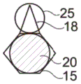
In the example shown in fig. 1A and 1B, the capillary trap 12 forms a cavity in the lower wall 8 having a constant height in the cross-section of the microfluidic system, in which cavity a droplet can settle. The capillary trap 12 has, viewed from above, a circular first trap region 15 and a triangular second trap region 18 adjacent to the first trap region 15.
The first and second trapping regions 15, 18 exert different trapping forces on a given droplet, particularly due to their different shapes. Here, the first trap region 15 exerts a larger trapping force than the second trap region 18.
When a first droplet 20 is introduced into the microfluidic system, it is trapped in a trapping region, in this case the first trapping region 15, having the greatest trapping force for that droplet. When the second droplet 25 is introduced, it is trapped in a vacant (free) trapping region, here the second trapping region 18, as shown in figure 2.
In the figure, the first droplet 20 is shown in black and the second droplet 25 is shown in transparent, but this does not represent a specific difference in content between the two droplets.
The diameter a of the first trapping region 15 is approximately equal to the apparent diameter D of the first droplet 20, as viewed from above once trapped in the first trapping region1。
The two captured droplets 20 and 25 are in contact with each other, in particular due to the small spacing between the two capture zones 15 and 18 with respect to the diameter of the two droplets 20 and 25. Furthermore, due to the triangular shape of the second trapping region 18, the two droplets 20 and 25 remain in contact. In fact, the second droplet 25 is in contact with two opposite walls 27 and 28 of the second capture zone 18, the walls 27 and 28 moving away from each other in the direction of the first capture zone 15, by which it naturally tends to always minimize its surface energy, so that the second droplet 25 is translated (move in translation) between the two opposite walls 27 and 28 in the direction of widening of the walls 27 and 28, i.e. towards the first capture zone 15 and therefore towards the first droplet 20.
In fig. 1A and 2, the two walls 27 and 28 form between them a divergence angle α substantially equal to 45 °.
In the example shown in fig. 2, the diameter D of the first droplet 201D is greater than second droplet 252。
The second trapping region 18 exerts a trapping force on the second droplet 25 that is greater than the trapping force it will exert on the first droplet 20. In fact, the diameter of the second droplet 25 is better adapted to the shape and size of the second trapping region 18 than the diameter of the first droplet 20, although the design of the second trapping region is the same regardless of the diameter of the droplet. However, other situations are possible, and the second droplet 25 may have the same diameter as the first droplet 20.
As a variant, the first droplet 20 and the second droplet 25 are mutually different in their other properties (in particular their surface state, their viscosity or their weight).
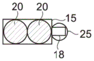
As a variant shown in fig. 3 and 4, the capillary trap 10 comprises two juxtaposed separate chambers, respectively forming a circular first trap region 15 and a triangular second trap region 18. The two trapping regions 15 and 18 of the capillary trap are close enough to bring the two trapped droplets 20 and 25 into contact with each other. Preferably, the distance e between the centers of gravity of the trapping zones 15 and 18 is less than (as shown in FIG. 4) or equal to (as shown in FIG. 3) the sum S of the radii of the two dropletsR。
Alternatively, as shown in fig. 5A and 5B, the first trap region may be hexagonal in shape, and the first trap region 15 may have h with the second trap region 182Different heights h1In particular h1Greater than h2. The first trap region 15 exerts a larger trapping force than the second trap region 18.
As a variant shown in fig. 6, the second trapping region 18 has the shape of a long triangle with a small divergence angle α, here approximately equal to 10 °, so that a string of second droplets 25, here two second droplets 25a and 25b, in contact with each other can be trapped. It can be said that the second trapping region 18 actually consists of two second trapping regions 18a and 18b so that each trapping region is capable of trapping a second droplet 25a and 25 b. In this case, the second droplet 25a is connected to the first droplet 20 via the second droplet 25 b. The trapping force exerted by the second trapping regions 18a and 18b on the second droplets 25a and 25b may differ depending on their location. Here, the second trapping region 18b exerts a stronger trapping force on the second droplet 25b closest to the first trapping region 15. However, depending on the shape of the second trapping region 18, other cases are possible.
As a variant not shown, the two second trapping regions 18a and 18b may exert the same force on the trapped second droplets 25a and 25 b.
As a variant not shown, the capillary trap may have more than two second trapping regions configured to form a string of trapped second droplets which are themselves in contact with the first droplets trapped in the first trapping region by at least one of the second droplets forming it.
More complex shaped capillary traps comprising multiple trapping regions configured such that the trapped droplets are all connected together either directly or by other droplets can therefore be envisaged.
As a variant shown in fig. 7 to 9, the capillary trap 12 has a plurality of identical second trapping regions 18 distributed around the first trapping region 15 such that each second droplet 25 trapped by one of the second trapping regions 18 is in contact with the first trapping region 20.
As shown, the second trapping regions 18 may be evenly distributed around the first trapping region 15. However, other situations are possible.
As a variant shown in fig. 10, the capillary trap 12 has a plurality of first trap regions 15, said first trap regions 15 being arranged in such a way that: the first droplets captured by the first capture zone 15 are each in contact with at least one other first droplet and a plurality of second capture zones 18. Here, the capillary trap 12 has two merged first trap regions 15 and two second trap regions, one of which merges into each first trap region.
As a variant shown in fig. 11, the capillary trap 12 may have a plurality of differently shaped second trap zones 18a and 18 b. The second trapping region can be configured to receive different second droplets 25a and 25 b. For example, as shown, the capillary trap has a second trap region 18a and a second trap region 18b, the second trap region 18a forming a single cavity with the first trap region 15, the second trap region 18b being separate from the first trap region 15. The second trapping regions 18a and 18b exert different trapping forces on the same droplet. The second trapping region 18a is for trapping a second droplet 25a, the diameter of said second droplet 25a being larger than the diameter of the second droplet 25b trapped by the second trapping region 18 b.
The present invention is not limited to the examples of shapes of the capillary trap 12 described above. The capillary trap 12 may have various shapes, particularly according to the desired application. Fig. 12 to 45 show conceivable shapes.
For example, as shown in fig. 12, the first trap region 15 may have a polygonal shape, particularly a square shape, and the second trap region 18 may have a triangular shape and merge into one side of the square.
As a modification shown in fig. 13, the second trap regions 18 are merged to corner portions of a square forming the first trap region 15.
As a variant shown in fig. 14, the second trapping region 18 has a rectangular shape, in particular a square shape.
As shown in fig. 15, the second trap region 18 may become wider in the direction of the first trap region 15 and may have opposite walls 27 and 28 having a curved profile in plan view, the second trap region 18 tapering towards its ends.
As shown in fig. 16, the capillary collector 12 may be heart-shaped, with the lobes of the heart forming two first traps 15 and the tip of the heart forming a second trap 18.
As shown in fig. 17, the first trap region 15 may have a pentagonal shape, and the second trap region 18 extends from a corner portion of the pentagonal shape.
As shown in fig. 18, the capillary trap 12 may have a hexagonal shape with the second trap region 18 extending from the side (side) of the hexagon.
The first trapping region 15 may have a square shape (as shown in fig. 19) or a circular shape (as shown in fig. 20), and the second trapping region 18 may have a circular shape.
As a variant, the second trapping region 18 has a triangular shape, but is connected to the first trapping region 15 by one of its corner portions, as shown in fig. 21. Therefore, the second trap region 18 becomes wider outward.
As another variant, the second trapping region 18 has a polygonal shape, in particular a hexagonal shape, as shown in fig. 22.
As another variation, the capillary trap 12 may include two second trap regions 18 that merge into the first trap region 15 at opposite corners of the first trap region 15, as shown in fig. 33.
As shown in fig. 23, the capillary trap 12 may have a first trap zone 15 of elliptical shape and two second trap zones 18 of triangular shape, said two second trap zones 18 merging with the first trap zone and extending opposite each other on one side of the first trap zone starting from the longer side of the ellipse.
As a modification shown in fig. 34, the second trapping region 18 has the same shape as in fig. 15.
As shown in fig. 24, the capillary trap 12 may have two second trapping regions 18 that are not evenly distributed around the first trapping region 15, but rather form a spacing angle β between the two second trapping regions 18.
The first trap region 15 may have a rectangular shape, and the second trap region 18 has a square shape, merging with the first trap region 15 through the short side of the rectangle. Depending on the size of the first droplet 20, the first trapping region 15 may then trap a single first droplet 20 (as shown in fig. 25) or a plurality of first droplets 20 (as shown in fig. 26).
As a modification shown in fig. 27, the second trap region 18 may be merged to the first trap region 15 by one long side of a rectangle.
The first trap region 15 may have an elliptical shape, and the second trap region 18 may merge into the first trap region 15 from a long side of the first trap region 15 (as shown in fig. 28) or merge into the first trap region 15 through a short side of the first trap region 15 (as shown in fig. 29).
The capillary trap may comprise a plurality of second trapping regions 18, at least two of which are different, in particular of different sizes, as shown in fig. 30.
In the example shown in fig. 31, the capillary trap 12 has the shape of a gourd, the bottom of which forms the first trap region 15 and the head of which forms the second trap region 18.
As a variant shown in fig. 32, the capillary trap 12 has a triangular shape, the portion near the wider bottom forming the first trap region 15 and the top forming the second trap region 18.
In the example shown in fig. 35, the first trap region 15 has a square shape, and the capillary trap 12 has two second trap regions 18 of the same square shape, each second trap region 18 merging by one of its corner portions to a corner portion of the first trap region 15.
In the examples shown in fig. 36 to 41, the capillary trap 12 has three second trap regions 18, and the first and second trap regions 15, 18 may each have all the shapes described above.
In the example shown in fig. 42 to 44, the capillary trap 12 has a plurality of differently shaped second trap regions. For example, one of the second trapping regions 18a has a triangular shape and the other of the second trapping regions 18b has a rectangular shape that is long enough to form a plurality of second trapping regions and trap a train of second droplets 25 (as shown in fig. 42), or the second trapping regions may have the shapes described above.
In cross section, the first and second trap regions 15 and 18 may have a constant height over their entire width.
As a variant shown in fig. 45, the first trapping region 15 has, in cross section, an edge that slopes towards the bottom of the cavity.
As another modification shown in fig. 46, the second trapping region 18 has a wall inclined toward the first trapping region. This notably makes it possible to keep the second droplet 25 in contact with the first droplet 20.
As another variation shown in fig. 47, the first and second trapping regions have at least one sloped wall.
As a variant shown in fig. 48, the capillary trap 12 is at least partially formed by the cavity of the upper wall 7 of the microfluidic system.
As a variant, the capillary trap 12 is at least partially formed by a cavity of one of the side walls of the microfluidic system.
As a variant shown in fig. 47, the capillary trap is formed by a cavity of the lower wall 8 and a cavity of the upper wall 7.
As a variant shown in fig. 63 to 65, the capillary trap is anisotropic and comprises a plurality of trapping regions with the same trapping force, so that the capillary trap traps a plurality of identical droplets in its respective region. For example, as shown in fig. 61 and 62, the capillary trap 12 may have an approximately triangular shape and may trap 3 or 4 identical droplets depending on the size of the droplets. As a variant shown in fig. 63, the capillary trap 12 has a five-armed star shape and is capable of trapping 5 or 6 identical droplets.
Microfluidic device
The channel 9 for the passage of droplets may comprise a plurality of capillary traps 12.
In particular, the channel 9 may comprise a two-dimensional trapping chamber 30, wherein the capillary traps 12 are spatially distributed according to two spatial directions in a table or matrix, as shown in fig. 49. In the figure, the capillary traps 12 are arranged at equal distances from each other in a plurality of arrays, but other cases are also possible. The capillary trap 12 may be arranged according to any periodic or aperiodic scheme.
The number of capillary traps 12 in the trapping chamber 30 can range from one per chamber to thousands per square centimeter.
The distance p defined between the centers of gravity of the capillary traps 12 is preferably greater than or equal to the size of the largest droplet to be trapped, in particular greater than or equal to the apparent diameter of the first drop (e.g. 20 μm to 1cm) as seen from above, said first drop being confined in the channel between the walls 7 and 8 outside the capillary trap.
The number of capillary traps may be greater than or equal to 200 capillary traps per square centimeter, and more preferably 2000 capillary traps per square centimeter. Thus, controlled combination of droplets can be performed in parallel in hundreds or even tens of thousands of trapping zones in the same trapping chamber 30.
The capillary trap 12 may be as described above.
The capillary traps 12 may all be identical.
As a variant, the at least two capillary traps 12 can be different, in particular by their shape, size, height or orientation, or by the number, shape, height or orientation of the first and second trapping regions 15, 18. This makes it possible to have different conditions depending on the capillary trap 12.
As a variant not shown, the channel 9 may be one-dimensional and comprise an array of capillary traps 12 distributed along its length.
The invention is not limited to the shape of the microfluidic system described above. Microfluidic systems may have different shapes, in particular different shapes depending on the desired application.
Micro-droplets
Preferably, the channel 9 is filled with a fluid immiscible with the droplet. The fluid may be stationary or moving. As the fluid moves, the flow of the fluid is preferably directed along a fluid flow line (not shown) and passes from the fluid inlet 31 to the fluid outlet 32.
The droplets are, for example, aqueous droplets in an oily liquid or droplets of oil in an aqueous liquid.
Preferably, the first droplet 20 and the second droplet 25 have a diameter D in the micrometer range1And D2And in particular from 20 μm to 5000 μm.
The first droplet 20 is preferably different from the second droplet 25, in particular with respect to its size and/or its composition.
The first droplet 20 or the second droplet 25 may form a set of droplets, wherein at least a number of the droplets are different.
The first droplet 20 and/or the second droplet 25 may comprise an identifying compound, allowing identification of the contacted first droplet 20 and second droplet 25 before, during, and/or after they merge. The identifying compound or compounds may be, for example, a number of beads or particles, compounds of various colors or shapes, or compounds that emit a colorimetric or fluorescent signal proportional to the concentration of the compound in the droplet. Where a set of first droplets and/or a set of second droplets contains different concentrations of a compound of interest and/or a different compound of interest, the location of the first droplets and/or the second droplets in the capture chamber can therefore be linked together with their composition to form a map of the droplets captured in the capture chamber.
As a variant, the recognition compound or compounds(s) of the first droplet interact with one or more recognition compounds of the second droplet to allow recognition of the droplet obtained after the fusion. For example, the fusion of the droplets may result in a chemical reaction in which at least one product may be identified.
Preferably, the channel 9 is filled with a fluid containing a surfactant. The surfactant allows stabilization of the droplets and reproducibility of their formation. Furthermore, the surfactant can prevent spontaneous coalescence of the droplets when they are transported from the production device to the capillary trap or in the case of contact in the capillary trap.
For aqueous droplets, the surfactant is, for example, selected from PEG-di-Krytox in fluorinated oils, or in mineral oils
80.
For microdroplets of oil, the surfactant is, for example, sodium lauryl sulfate.
As a variant, the microdroplets are stabilized by some other means, in particular they may be gelled, or stabilized by adsorption of amphiphilic nanoparticles, as described in the following articles: pan, M., Rosenfeld, L., Kim, M., Xu, M., Lin, E., Derda, R., & Tang, S.K.Y. (2014.) Fluorinated Pickering Emulsions interaction Transport and Form Rigid Interface for the Growth of antibiotic-Dependent cells applied Materials & Interfaces, 6, 21446-.
Operating method
Fig. 52 shows an example of a method of manipulating a first droplet and a second droplet.
A first droplet 20 is produced in step 40. A number of methods have been proposed for forming these first droplets in the mobile phase. For example, the following methods may be mentioned:
a) a method called "flow focusing" described in, for example, the following: s.l.anna, n.bontoux and h.a.stone, "" format of dispersion using 'Flow-Focusing' in microchannels ", appl.phys.lett.82, 364(2003), the contents of which are incorporated herein by reference,
b) for example, a process known as "step emulsification" described below: r.seemann, m.brinkmann, t.pfohl and s.herminghaus, "Droplet based microfluidics," rep.prog.phys., volume 75, phase 1, page 016601, month 1 2012, the contents of which are incorporated herein by reference,
c) for example, by the combined methods "flow focusing" and "step emulsification" described below: chokkalingam, S.Herminghaus, and R.Seemann, "Self-synchronizing thread production of monitoperserperpene by microfludic step implementation," appl.Phys.Lett., Vol.93, No. 25, p. 254101, 2008, the contents of which are incorporated herein by reference,
d) for example, the method called "T-connection" described by: G.F.Christopher and S.L.Anna, "Microfluidic methods for generating continuous loop streams," J.Phys.D.appl.Phys., Vol.40, No. 19, pages R319-R336, month 10 2007, the contents of which are incorporated herein by reference,
e) a method called "constrained gradient" is described, for example, by: R.Dangla, S.C.Kayi and C.N.Baroud, "Droplet microfluidics drive by gradients of defilement," Proc.Natl.Acad.Sci.U.S.A., Vol.110, No. 3, p.853-
f) For example, a method called "micro-segmented streaming" described by: funfak, r.hartung, j.cao, k.martin, k.h.wiesmuller, o.s.wolfbeis, and J.M. "high-reduced dose-response functions for a drug-modulated bacterial by fluorometric and fluorometric flow-through sensing in microsegmented flow," Sensors Actuators, B chem., Vol.142, No. 1, pp.66-72, 2009, the contents of which are incorporated herein by reference, wherein two solutions of different controlled ratios are usedA method of mixing at a functional level outside a microfluidic system, forming microliter drops separated from immiscible phases, and then separating these drops into droplets by, for example, injecting these microliter drops into a microfluidic system containing a ramp.
These methods make it possible in particular to form a plurality of droplets having approximately equal size. The size of the droplets obtained can be controlled by varying the droplet formation parameters, in particular the flow rate of the fluid in the device and/or the shape of the device.
The first droplet 20 may be produced on the same microfluidic system as the method or on a different device. In the latter case, the first droplet 20 may be stored in one or more external containers before injection into the microfluidic system. These first droplets 20 may all be the same, or some of them may have different compositions, concentrations and/or sizes.
After the formation of the first droplets 20, said first droplets 20 may be transported to the capillary collector 12 by fluid flow entrainment and/or by ramp or bump entrainment in the form of a rail of the channel 9. In both cases, the addition of a guide rail can selectively optimize the filling of the capillary trap 12, for example in combination with the use of an infrared laser, as described below: fradet, C.McDougal, P.Abbyad, R.Dangla, D.McGloin, and C.N.Baroud, "Combining threads and anchors with laser for selecting for selective manipulation with 2D droplet arrays," Lab Chip, Vol.11, No. 24, p.4228, 4234, 12 months 2011.
If the production of droplets is performed outside the microfluidic system, they may be transported directly from the reservoir to the microfluidic system by connecting e.g. the tubes of the production system and the capture system, or by sucking and injecting with a syringe.
The first droplets 20 are entrained in the microfluidic system such that they are subjected to an entrainment force that is less than the trapping force of the first trapping region 15 on the first droplets 20. The first droplet 20 is then trapped in the capillary trap 12, in particular in the first trapping region 15, in step 42. If the entrainment force exerted by the entrainment stream on the first droplet 20 is greater than the trapping force of the second trapping region 18, the first droplet 20 is not trapped in the second trapping region 18 that remains vacant.
Otherwise, the first droplet 20 may be trapped in the second trapping region 18, especially if the traps and droplets are of suitable size. The first droplets 20 may then be removed from the second catch zone 18 by increasing the entrainment force applied to all of the first droplets 20, for example by increasing the velocity of the fluid stream, or by adding a fluid stream in step 44 when there is no fluid stream.
As a variant, the first droplet 20 may be formed by a method known as "breaking a droplet in a capillary trap" as described, for example, in international application WO2016/059302, the contents of which are incorporated herein by reference. In this case, the first droplet 20 is formed directly in the first trapping region 15.
A second droplet 25 is produced in step 46. This step is shown after step 44, but may be performed first. A second droplet 25 may be generated and introduced into the microfluidic system as described above with respect to the first droplet 20.
The second droplet 25 is entrained in the microfluidic system in this way: such that they are subjected to an entrainment force that is less than the trapping force of the second trapping region 18 on the second droplet 25. The second droplet 25 is then captured in the second capture zone 18 in step 48. When the second droplet 25 is entrained by the fluid stream, the fluid stream exerts an entrainment force on the first droplet 20 captured in the first capture zone 15, which is preferably less than or equal to the capture force of the first capture zone 15 on the first droplet 20, such that the first droplet 20 remains captured.
At each stage, the method may include the step of first measuring the state of the system. The measurement may be a simple imaging or, for example, a colorimetric measurement, a fluorescence measurement, a spectroscopic (UV, raman) measurement or a temperature measurement. This measurement may be particularly useful in the case of using different sets of first and/or second droplets 20 containing an identifying compound as described above.
When several droplets are contacted in the same trap, they can be fused in a controlled manner to mix their contents in step 50. The coalescence may or may not be selective.
To fuse all droplets in the microfluidic system, in particular in the capture chamber 30, which are in contact, the microfluidic system is primed with a fluid that is free of surfactant. The concentration of the surfactant in the fluid of the microfluidic system is reduced, which makes it possible to shift the adsorption equilibrium of the surfactant at the interface to desorption. The droplets lose their stabilizing effect and spontaneously merge with the droplets with which they come into contact.
As a variant, the microfluidic system is perfused with a fluid containing a destabilizing agent. In the case of aqueous droplets, the destabilizing agent is, for example, 1H,2H, 2H-perfluorooctan-1-ol in fluorinated oil.
As another variant, all droplets in contact in the microfluidic system, in particular in the capture chamber 30, are fused by applying an external physical stimulus (e.g. a mechanical wave, a pressure wave, a temperature change or an electric field). As shown in fig. 50, electrodes 35 may be placed on either side of the capture chambers to fuse all droplets that are in contact between the capture chambers.
To selectively fuse the droplets, an infrared laser may be used, as described below: e.fradet, p.abbyad, m.h.vos and c.n.baroud, "Parallel measurements of interaction kinetics using ultra low volumes," Lab Chip, vol 13, No. 22, p 4326-.
The present invention is not limited to the above-described examples of aggregation. Any method that makes it possible to destabilize the interface between two droplets in contact may be used for the merging droplet.
The status of the obtained droplets may then be measured and/or the droplets observed in real time. This makes it possible, for example, to study the kinetics of chemical or biochemical reactions.
Selective trapping
When the capillary trap 12 or capillary trap(s) 12 has a plurality of second trapping regions 18, the position of the second trapping region 18 or second trapping region(s) 18 in relation to the direction and feel (sense) of the entrainment force exerted on the second droplet 25 may allow for selective trapping.
Taking the case of a capillary trap as an example, it has two second trap zones 18m and 18v arranged on either side of the first trap zone 15 and aligned in the direction of the applied entrainment force, as shown in fig. 53. After trapping the first droplet 20 at the level of the first trapping region 15 according to step 44, the second droplet 25m is provided with the following direction F according to step 48a1Directed entrainment force. If the trapping force in the second trapping regions 18m and 18v is sufficiently low, the second droplet 25m is trapped only in the opposite direction F1In the second trapping region 18m upstream of the first trapping droplet 20. Even if the downstream second trapping region 18v is the same, its position relative to the second droplet 25m is different, because in the case of a fluid, the flow line of the second droplet 25 bypasses the first droplet 20, avoiding the second trapping region 18 v. Furthermore, the presence of the captured first droplet 20 facilitates keeping the second droplet 25m captured upstream, the second droplet 25m being able to rest on the first droplet 20. After upstream capture of the second droplet 25m, a bead F may be applied to the second droplet 25v1Opposite direction F2Directed entrainment force to trap one of the second droplets 25v in the still vacant second trapping region 18v according to step 48 b.
As shown in fig. 54, the location of the second catch zone 18 or second catch zone(s) 18 in relation to the direction and feel of the entrainment force exerted on the second droplets 25 may also be used to perform selective release to catch, for example, another, different second droplet 25 in one or more of the second catch zones 18. Taking the former case of a capillary trap as an example, if the trapping forces in the second trapping regions 18m and 18v are each strong enough to trap the second droplet 25m, regardless of the direction of the entrainment force exerted on the second droplet 25m in step 48a, when such an entrainment force is applied, relative to that in F3The fact that the second droplet 25m, which is directionally oriented upstream of the entrainment force, is retained better than downstream may be used to selectively release the droplets trapped at step 52The downstream second droplet 25 m. In fact, the first droplet 25m may be deformed and may rest on the first droplet 20 trapped in the first trapping region 15, thus releasing the first droplet 25m with a stronger force than the force required to release the downstream second droplet 25 m. A second droplet 25v, different from the second droplet 25m already captured in step 48b, may then be captured in the released second capture zone 18 v.
Timing (chronology) examples of droplet capture
In the embodiment of a capillary trap having two trapping regions shown in fig. 66, the ordinate of the graph 66 shows the strength of the trapping force compared to the hydrodynamic drag force, and the abscissa shows time, the method comprising the steps of:
trapping the first droplet in a first zone of the capillary trap, the trapping force F4 exerted by the first zone on the first droplet being greater than the hydrodynamic drag force Ft1 exerted by the stream on the first droplet, such that the first droplet remains trapped in the first zone, the drag force Ft4 being between F4 and F5, F5 representing the trapping force exerted by the second zone of the capillary trap on the first droplet,
-then trapping the second droplet in a second zone of the capillary trap, the hydrodynamic drag force Ft5 exerted by the stream on the second droplet during loading of the second droplet in the second zone being between F5 and F3, F3 preferably being less than F4, F3 being the trapping force exerted by the second zone of the trap on the second droplet. The drag force Ft5 is less than F4.
Thus, selective trapping of two droplets is obtained in two zones of the capillary trap, respectively.
Trapping according to droplet size
The second capture zones 18 of the various capillary traps 12 in the same microfluidic system may have different characteristics, in particular different sizes. This makes it possible, for example, to trap different second droplets 25 in different capillary traps 12 in order to obtain different droplets. For example, for a given concentration of an element contained in a second droplet, the amount of the element contained in the second droplet depends on the size of the second droplet. Thus, by creating, for example, different sized second trapping regions 18 in the same trapping chamber 30, different sized second droplets 25 can be selectively trapped, where the size of the second droplet 25 corresponds to each size of the second trapping region 18.
Fig. 55 shows three capillary traps 12a, 12b and 12c with different sizes of the second trapping regions 18a, 18 and 18 c. The first trapping region 15 is filled with a first droplet 20. Second droplets 25a, 25b and 25c are provided all having the same concentration but having different sizes. The second trapping regions 18a, 18b and 18c each correspond to one size of a second droplet, and then the second droplets 25a, 25b and 25c are trapped in the second trapping region 18a, 18b or 18c to which they best correspond.
It is preferred that the capillary traps 12a, 12b and 12c are placed by increasing the trapping force of the second trapping regions 18a, 18b and 18c relative to the largest of the second droplets 18a in the direction of the entrainment force of the second droplets in the microfluidic system, especially in the direction of the fluid flow. Thus, the second droplets 25a, 25b and 25c first encounter the second trapping region 18c (in which only the smallest second droplet 25c is trapped), then encounter the second trapping region 18b (in which only the second droplet 25b is trapped), and finally encounter the second trapping region 18a (in which the largest second droplet 25a is trapped).
As a variant, the other parameters of the droplets 25a, 25b and 25c are different, and they comprise in particular different elements.
This makes it possible to obtain a set of droplets, at least some of which are different, in particular in terms of their compound concentration and/or their composition.
Sequential coalescence
As shown in fig. 56, steps 46, 48, and 50 may be repeated to perform sequential coalescence. In each capillary trap 12, the droplet obtained after step 50 becomes a new first droplet 80, the first droplet 80 having as its volume the sum of the volumes of the first droplet 20 or first droplet(s) 20 and the second droplet 25 or second droplet(s) 25 merged in the capillary trap 12. When the second trapping region 18 or second trapping region(s) 18 are again empty, one or more third droplets 58, which may be the same as or different from the initial second droplet 25 or second droplet(s) 25, may be provided to perform a new coalescence and obtain a new droplet 90, which itself becomes a new first droplet, and so on. As coalescence continues, the droplet will become larger by adding different volumes of coalesced droplet until it becomes so large that it prevents new droplets from being trapped in the second trapping region 18. The maximum number of coalescence that can be performed in the same capture capillary 12 depends on the volume of the successively coalesced droplets.
Note that if the coalescence step consists of: removal of the surfactant from the external phase or including chemical destabilization of the surfactant, a stabilization step may be required between different coalescence. In practice, the capture chamber must be primed with a fluid that is immiscible with the surfactant-containing droplet before one or more new droplets are brought into the capillary trap.
The ability to perform sequential aggregation has several applications. If the first droplet 20 trapped in the first trapping region 15 of the capillary trap 12 comprises cells (e.g., bacteria, yeast or mammalian cells), sequential coalescence may allow the medium to be refreshed several times by fusing the second droplets 25 containing the medium sequentially at a predetermined time.
This may also be used to simulate the intermittent administration characteristics of a drug product. For example, a first droplet 20 containing mammalian cell spheroids and captured in the capillary trap 12 fuses every 6 hours with a second droplet 25 of the drug.
Concentration gradient of drops
The capillary trap 12 in the trapping chamber 30 can be different and its position can be controlled. It is possible, for example, for the capillary trap 12 to have a different number of second trapping regions.
As shown in fig. 57, the capture chamber 30 can include capillary traps 12a, 12b, 12c, and 12d having one, two, three, and four identical second capture zones 18, respectively, evenly distributed around the first capture zone 15. If the first droplet 20 is the same and contains a compound of interest, after coalescence with the captured second droplet 25, which may for example contain a diluent, droplets 100, 105, 110 and 115 may be obtained in the microfluidic chamber, forming a spatial gradient of four concentrations of the compound of interest, here represented by different grey scales.
Set of microdroplets
Injecting groups of droplets containing different compounds and/or different concentrations in a chamber containing the capillary trap 12 as described above provides many applications.
At 2cm2For example, trapping chambers (each with 1000 capillary traps) such that the first droplet 20 and the second droplet 25 can be trapped. The first droplet 20 forms a set of droplets containing 20 different concentrations of the first compound. Second droplet 25 contains 10 different concentrations of the second compound. By fusing the first droplet 20 and the second droplet 25 in the capillary trap 12, droplet matrices may be obtained, each droplet matrix corresponding statistically to one of 200 possible combinations of the first droplet 20 and the second droplet 25.
The fact that the droplets are static also makes it easier to obtain kinetic data. There is also the advantage of reagent economy by using very small volumes in the droplets.
The compounds contained in the first droplet 20 and the second droplet 25 may be chemical molecules that react with each other and their initial concentrations need to be optimized. The above process allows large scale combinatorial chemistry. The droplet may include one or more identifying means. This may allow, for example, the concentration of the final product to be measured, for example by fluorescence or spectroscopy.
As a variation, first droplet 20 and/or second droplet 25 may contain various concentrations of proteins, enzymes, and cells.
The microfluidic systems and methods described above allow for the study of protein crystallization. In fact, obtaining crystals from a purified protein solution is an essential step in determining its three-dimensional structure, since this makes it possible to obtain an X-ray diffraction pattern. However, proteins are always obtained in very small amounts, and the optimum crystallization conditions vary from protein to protein.
For example, a capture chamber 30 having a number of capillary traps 12 is used, each of which allows the capture of a first droplet 20 and a second droplet 25, resulting in a first set of droplets comprising different concentrations of saline solution and a second set of droplets comprising different concentrations of a protein of interest. By fusing the first droplet 20 and the second droplet 25 in the capillary trap 12, a droplet matrix representing conditions of different concentrations of saline solution and protein can be obtained, enabling determination of the concentration that allows optimal protein crystallization.
By immobilizing a first droplet 20 on the capillary trap 12, said first droplet 20 comprising an element of interest having the same concentration throughout the trapping chamber, and by fusing the first droplet 20 with a second droplet 25 obtained from a set of droplets containing different concentrations of the titrating substance, the substance of interest contained in the first droplet 20 can be titrated. This application may be particularly advantageous in the case of expensive or low amounts of available reagents.
The methods described herein may also be very useful for screening drugs. For example, cancer cells may be cultured in individualized form or in the form of spheroids in the first droplets 20 captured in each first capture zone 15 of the capillary trap 12, and after several days of culturing, the first droplets 20 in each trap may be coalesced with second droplets 25 containing the drug to be screened, the second droplets 25 being obtained from a set of droplets containing different drugs.
In a similar configuration, it is conceivable to culture hepatocytes in spheroid form in the captured first droplets 20 and to supply each capillary trap 12 with a second droplet 25 containing a drug whose toxicity it is desired to assess, each droplet being obtained from a set of droplets containing a different concentration of the drug. By analyzing the results of the survival several days after coalescence, the concentration of the drug that kills half of the cell population can be inferred, for example.
The method may also allow the evaluation of the interaction between different antibiotics. A set of second droplets 25 containing one or more antibiotics at different concentrations can be created and fused with the first droplet 20 containing bacteria in capture chamber 30. The first droplet 20 may contain different concentrations of bacteria. This makes it possible to explore a space with 3 parameters.
The use of microfluidics can be very advantageous in the case of rare samples, such as biopsies. Microfluidic systems may be used, for example, in the context of personalized medicine and cancer therapy. With this system it is possible to culture tumour cells from a patient undergoing biopsy, for example in the form of spheroids in the captured first droplets 20, and subject said tumour cells to a plurality of concentrations of different drugs by feeding the second droplets 25 into the capture chamber 30. After the coalescence of droplets with cells and droplets with drug, the most effective drug and its concentration for a particular patient can be determined using only a single capture chamber 30 and the minimum number of cells obtained from the biopsy.
Tissue engineering
The methods described above can allow for the fusion of microdroplets containing cells, which may or may not have different cell types, to precisely form a microtissue.
The capillary trap may be as shown in fig. 5A and 5B. Preferably, the height of the first trapping region 15 is such that its volume is greater than the volume of the first droplet, such that the trapped first droplet 20 has an uneven bottom, in particular a convex bottom, as shown in fig. 5A. Thus, the cells contained in said first droplet 20 slide along the interface of the first droplet 20 during sedimentation and aggregate at the bottom of the captured first droplet 20 and form a spheroid, as described in international application WO2016/059302, which is incorporated herein by reference.
The first droplet 20 may comprise cells of a first cell type in a liquid medium and may be captured in the first capture zone 15 of the capillary trap 12 to spontaneously form a first spheroid by sedimentation of cells after one day of immobilization. Preferably, the microfluidic system has no fluid flow in the vicinity of the capillary trap during formation of the first sphere, so that no liquid movement of the first droplet 20 is induced. A second droplet 25 of cells of a second cell type contained in the liquid medium may be captured in the second capture zone 18. After coalescence of the first and second droplets, two different types of cell cultures are obtained, the structure of which depends inter alia on the experimental conditions.
If the first droplet 20 is liquid, the cells of the second droplet 25, after coalescence, mix with the contents of the first droplet 20 and then settle, directly providing spheroids of cells of the first cell type.
If the cells of the second droplet 25 have time to form a second spheroid before coalescence, coalescence of the two droplets 20 and 25 results in fusion of the first and second spheroids.
If coalescence occurs before the cells of the second droplet 25 have time to form spheroids, the cells will settle after settling on the surface of the first spheroids.
If one of the two droplets 20 or 25 is now gelled prior to the coalescence operation, the two cell populations are regionally separated. Indeed, if the first droplet 20 containing the first spheroid gelled before the second droplet 25 reached, after coalescence of the droplets 20 and 25, the cells of the second cell type would no longer be able to come into direct contact with the first spheroid due to the presence of the gel. For example, mammalian cells cannot pass through a 0.9 wt% agarose matrix. The two groups of cells can communicate with each other only through the paracrine route.
The example given here is a capillary trap 12 for trapping the first droplet 20 and the second droplet 25, but more complex microtissue structures can be obtained where the capillary trap 12 allows trapping more than two droplets and/or a method as described above consisting of merging several droplets in sequence by changing or not changing the orientation of the fluid stream. Multiple microtissue can also be formed in parallel using multiple capillary traps as described above.
This technique for forming microtissue makes it possible to produce microtissue with controlled structure in vitro, thereby very faithfully simulating the conditions encountered in vivo. In fact, in vivo, different cell types are often arranged in tissues according to specific structures, which is important for re-establishing function at the organ level.
Reconstructing function at the organ level may also be used for transplantation purposes in patients. For example, glucagon-producing alpha cells and insulin-producing beta cells can be combined to produce langerhans islets that are intended to be transplanted into the pancreas of a patient to treat diabetes. Similarly, hepatocytes and stellate cells may be combined in the case of liver transplantation.
Hydrogels
The methods described above may also be used to generate multi-layered gel droplets.
The capillary trap 12 may be as described above, and may include a first trap region 15 and a second trap region 18.
As shown in fig. 58, first droplets 20 containing a first gellable medium may be captured in a first capture zone 15, and the first gellable medium may then be gelled to form droplets 200 of a first gel, as shown at step 54. Then, according to step 58, droplets 200 of the first gel may be merged with second droplets 25 comprising the second gelable medium and captured in the second capture zone 18 in step 56. After this coalescence, the second gellable medium may be gelled to form an outer layer 202 of the second gel on the first gel. This operation may be repeated several times in sequence to form droplets having a core of the first gel and multiple successive outer layers of other gels.
As a variation shown in fig. 59, the second gellable medium contained in the second droplet 25 is gelled to form a second gelled droplet 204 prior to being merged with the first droplet. When the two droplets merge, they retain their shape and position prior to merging and form gelled droplets 210 having a shape that depends on the shape, arrangement and number of trapping regions.
The method can also result in spheroids encapsulated in a biological hydrogel.
To be controlled byThe means for forming spheroids in the droplets must be capable of retaining the contents of the droplet liquid during the formation of the spheroids. Agarose is well suited for this protocol because it is a thermosensitive hydrogel. Agarose remains liquid at 37 ℃ (ultra-low gelling agarose), then solidifies after 30 minutes at 4 ℃, and remains solidified after returning to 37 ℃. However, mammalian cells cannot adhere to agarose and cannot digest agarose. Thus, the matrix is very different from the extracellular matrix encountered in vivo. To better mimic natural conditions, it is preferred to use hydrogels, such as collagen type I, fibronectin, collagen, or a combination thereof, Or gelatin. However, controlling their gelation is more difficult. For example, type I collagen cannot be kept in a liquid state under good conditions (low temperature or acidic pH) for cell culture for a long time. If the cells are encapsulated in collagen droplets that rapidly gel after capture, rather than adhering to each other and forming spheroids, the cells will adhere to the collagen and move individually along its fibers.
This problem can be solved with the method according to the invention.
The capillary trap may be as shown in fig. 5A and 5B. Preferably, the height of the first trapping region 15 is such that the trapped first droplet 20 has an uneven bottom, in particular a convex bottom, as shown in fig. 5A, such that cells contained in said first droplet 20 slide along the interface of the first droplet 20 during sedimentation and aggregate and form spheroids at the bottom of the trapped first droplet 20, as described in international application WO2016/059302, which is incorporated herein by reference.
The first droplet 20 may comprise cells of a first cell type in a liquid medium and may be trapped in the first trapping region 15 of the capillary trap 12 to form spheroids spontaneously by sedimentation of the cells after one day of immobilization. Preferably, the microfluidic system has no fluid flow in the vicinity of the capillary trap during spheroid formation so as not to cause liquid movement of the first droplet 20. A second droplet 25 containing a high concentration of one of the above-described biological hydrogels may be captured in the second capture zone 18. Once this second droplet is captured, the two droplets immediately merge, allowing the still liquid biological hydrogel to mix with the first droplet containing the spheroid. Gelation then occurs and the spheroids are encapsulated in an extracellular matrix representing the biological conditions encountered in vivo.
This spheroid encapsulation technique can be combined with the technique described above for forming microstructures to allow more complex microstructure to be obtained.
The following non-limiting examples describe embodiments of the invention as described above.
Example 1
Experiments were performed to demonstrate the feasibility of the method.
The collection chamber 30 used was 2cm2And contains 393 identical capillary traps similar to those in fig. 1A, 1B and 2, and having the following dimensions:
a=250μm,
b=c=150μm,
h100 μm, and
h=50μm。
the capillary traps 12 are distributed according to a matrix, as shown in fig. 49.
The droplets contain a food dye. 1 μ L of droplets with five different colors from blue to green to yellow were formed by the "micro-segmented flow" technique. Using a ramp (method described at point f) above) to separate these 1 mul drops into a number of monodisperse nanoliter first droplets 20. These first droplets 20 of each color are then mixed to form a first set of droplets comprising different colors, which are then injected into a capture chamber 30 comprising a capillary trap 12. The first droplet 20 is sized to fully occupy the first trapping region 15. The second trapping region 18 remains empty.
In the same way, a drop of 1 μ L of five shades from clear, colorless to red is formed and then separated into a second droplet smaller than the first droplet due to the differentially designed slopes. These second droplets are mixed to form a second set of droplets comprising different colors, which are then injected into the microfluidic chamber where they are trapped in the second free trapping region 25.
A matrix of pairs of first droplets 20 and second droplets 25 is then obtained as shown in fig. 60 a). Thus, 25 different pairs are possible. The contacted first droplet 20 and second droplet 25 are merged by filling capture chamber 30 with HFE-7500 containing 1H, 2H-perfluorooctan-1-ol at a concentration of 20% by volume. The colors of the two droplets that are in contact in each capillary trap mix and appear in one of 25 possible colors depending on the color of the initial droplet, as shown in fig. 60 b). A matrix of droplets with 25 different colors was then obtained.
This experiment shows that different reagents of different concentrations can be combined in parallel in the same trap in the trapping chamber 30 after coalescence with pairs of different compositions.
Example 2
Experiments were performed to obtain spheroids resulting from the fusion of two consecutive separate spheroids.
The microfluidic system comprises a trapping chamber 30 with a matrix of capillary traps, as shown in fig. 5A and 5B, said trapping chamber 30 having the following dimensions:
h165 μm, and
h1=388μm,
h2=80μm,
c=200μm,
a=400μm。
rat hepatocytes (H4IIEC3) are first encapsulated in the first microdroplet 20. The first droplet 20 is captured in the first capture zone 15 and, after settling, the cells aggregate at the bottom of each drop to form a first spheroid 130. After the day required for these first spheroids to form, the second droplets 25 are captured in the second capture zone 18, as shown in figure 61A. The second droplet 25 also contains H4IIEC3 cells, but the second droplet 25 is fluorescently labeled as compared to the first droplet 20 Dyed red. These pairs of first and
 second droplets 20, 25 are left as they are for one day so that the red cells of the second droplets 25 aggregate and form a second spheroid 135 at the bottom of each second droplet 25. The contacted first and second droplets were then merged by pouring into the chamber HFE-7500 (fluorinated oil) containing 1H, 2H-perfluorooctan-1-ol at a concentration of 20% by volume.
After coalescence in each trap, the second spheroid 135 settles and contacts the first spheroid 130 in the new first droplet 140 at the bottom of the first droplet, as shown in fig. 61B. The two contacted spheroids will adhere to each other and fuse to form only a single new spheroid, where the two portions 130 and 135 are clearly identifiable by fluorescence imaging (cells from the second spheroid will continue to appear red in the fused spheroid). The chamber was then filled with oil containing a surfactant to restore the stability of the new first droplet for the remainder of the experiment.
This operation was then repeated, this time with the package already dyed green (CellTracker) ) As shown in fig. 61C, a
 third droplet 85 of H4IIEC3 cells. Similarly, as shown in FIG. 61D, a third green spheroid 145 is formed in third droplet 85, and then third droplet 25 is merged with the new first droplet, as shown in FIG. 61E. The contacted third green spheroid 145 and new spheroid 140 will adhere to each other and fuse to form only a single spheroid having three portions clearly identifiable by fluorescence imaging.
Thus, a matrix of three-color spheroids is finally obtained, as shown in fig. 62, and three different color spheroids can be identified in each of fig. 62.
This experiment demonstrates the potential of this technique in applications related to tissue engineering. Indeed, it is easily conceivable to fuse spheroids of complementary cell types instead of spheroids of the same cell type but with different colours to create functional microtissue with well-defined structures.
Example 3
Experiments were performed to determine which concentrations of drug (acetaminophen) over which the hepatocytes (rat hepatoma cells, H4IIEC3 cells) became toxic in a single microfluidic system.
The microfluidic chamber used in FIGS. 5A and 5B was at 2cm2The upper contains 252 identical traps.
A first droplet 20 of agarose which is liquid (ultra-low gelation) at 37 ℃ (diluted to 0.9% by weight in medium containing H4IIEC3 cells) is trapped in the first trapping region 15, and the second trapping region 18 remains vacant. The first droplet 20 is then cultured for one day to allow the cells to adhere to each other to form spheroids through the first droplet 20. The first droplet 20 is then gelled by applying a temperature of 4 ℃ for 30 minutes.
Meanwhile, acetaminophen is dissolved in a medium at a high concentration. To this solution was added fluorescein at high concentration. The obtained solution was diluted with pure medium to different concentrations to form 1 μ L drops of different concentrations. These droplets are then separated by means of a ramp into second droplets 25, then mixed and then injected into the capture chamber 30 containing the first droplets 20. These second droplets 25 are smaller than the first droplets 20 and are captured in the second capture zone 18.
By taking a fluorescence image prior to fusing, different fluorescence levels associated with the concentration of the drug in second droplet 25 may be identified. Even if the drops were randomly fixed in the trap, the concentration of acetaminophen bound at the capillary trap 12 corresponding to each spheroid could be found.
The chamber was filled with HFE-7500 (fluorinated oil) containing 1H,1H,2H, 2H-perfluorooctan-1-ol at a concentration of 20% by volume to fuse the contacted droplets. Then, acetaminophen diffuses through the gelled agarose and acts on the cells. After one day of exposure to acetaminophen, the oil separating the droplets from each other was replaced with an aqueous phase to color the spheroids with a fluorescent survival marker present in the aqueous phase, as described in international application WO 2016/059302. By taking an image of the final substrate, the spheroids whose survival is most affected can be determined. It was found that the higher the concentration of acetaminophen, the fewer cells survived. Thus, correlating the survival results with the concentration of acetaminophen in the second droplet, it can be determined that acetaminophen toxicity to these hepatocytes ranges from 10mmol/L to 30mmol/L for 1 day of static exposure.
Work leading to the present invention resulted in the funding of the european research council in the context of the european union seventh framework project (FP7/2007-2013)/ERC grant protocol No. 278248.
Claims (39)
1. A method for manipulating at least one first liquid droplet (20) and at least one second liquid droplet (25, 25a, 25b, 25c, 25m, 25 v) in a microfluidic system comprising a capillary trap (12, 12a, 12b, 12 c) having a first trapping region (15) and a second trapping region (18, 18a, 18b, 18c, 18m, 18 v), the method comprising the steps of:
(i) trapping said first liquid droplets (20) in said first trapping zone (15), and
(ii) trapping the second liquid droplet (25, 25a, 25b, 25c, 25m, 25 v) in the second trapping region (18, 18a, 18b, 18c, 18m, 18 v),
the first and second trapping regions (15, 18a, 18b, 18c, 18m, 18 v) are arranged in such a way that: bringing the first liquid droplet (20) and the second liquid droplet (25, 25a, 25b, 25c, 25m, 25 v) into contact with each other,
the first and second trapping regions (15, 18a, 18b, 18c, 18m, 18 v) are configured in such a way that: such that the trapping forces to be exerted by the first trapping region (15) and by the second trapping region (18, 18a, 18b, 18c, 18m, 18 v) on the same first liquid droplet (20) or second liquid droplet (25, 25a, 25b, 25c, 25m, 25 v) will be different, the first liquid droplet (20) being trapped in the first trapping region (15), the trapping force exerted by the first trapping region (15) on the first liquid droplet (20) being greater than the trapping force exerted by the second trapping region (18, 18a, 18b, 18c, 18m, 18 v) on the first liquid droplet (20),
the first liquid droplet (20) is moved in step (i) in the microfluidic system by an entrainment force greater than the trapping force exerted by the second trapping region on the first liquid droplet (20) and less than or equal to the trapping force exerted by the first trapping region on the first liquid droplet (20).
2. The method according to claim 1, the at least one second liquid droplet (25, 25a, 25b, 25c, 25m, 25 v) having a smaller size or a smaller volume than the first liquid droplet (20).
3. The method of claim 1, the first liquid droplet (20) and the second liquid droplet (25, 25a, 25b, 25c, 25m, 25 v) being different or having different contents.
4. The method of claim 1, the capillary trap (12, 12a, 12b, 12 c) comprising a plurality of second trapping regions (18, 18a, 18b, 18c, 18m, 18 v), step (ii) consisting of: each second trapping region (18, 18a, 18b, 18c, 18m, 18 v) traps one second droplet of liquid (25, 25a, 25b, 25c, 25m, 25 v), said first trapping region (15) and said second trapping region (18, 18a, 18b, 18c, 18m, 18 v) being arranged in such a way that: such that each second liquid droplet (25, 25a, 25b, 25c, 25m, 25 v) is in contact with at least one of the first liquid droplet (20) or the second liquid droplet (25, 25a, 25b, 25c, 25m, 25 v).
5. The method according to claim 4, step (ii) comprising sub-steps (ii ') and (ii "), said sub-step (ii') consisting of: fluid flow (F) in a first orientation1) By trapping a second liquid droplet (25 m) in one or more of said second liquid dropletsIn the two trapping regions (18 m), said sub-step (ii ") consists of: fluid flow (F) in a second orientation2) Is caused to trap a second liquid droplet (25 v) in another one or more further portions of the second trapping region (18 v), the first and second directed fluid streams having different orientations.
6. The method of claim 1, comprising step (iii) consisting of: -fusing the second liquid droplet (25, 25a, 25b, 25c, 25m, 25 v) or each of the second liquid droplets (25, 25a, 25b, 25c, 25m, 25 v) captured in the second capture region (18, 18a, 18b, 18c, 18m, 18 v) or each of the second liquid droplets (25, 25a, 25b, 25c, 25m, 25 v) with the first liquid droplet (20).
7. The method of claim 6, comprising a step (v) after step (iii), consisting of: trapping a third droplet (85) in one or more of the second trapping regions (18, 18a, 18b, 18c, 18m, 18 v) no longer having a second liquid droplet, such that the first liquid droplet (20) and the third droplet (85) are in contact with each other.
8. The method of claim 7, the droplets (20, 25a, 25b, 25c, 25m, 25v, 85) being supplied randomly to the trapping zone (15, 18a, 18b, 18c, 18m, 18 v).
9. Method according to claim 1, the height (h) of the first trapping region (15) being such that1) Such that the volume of the first trapping region (15) is greater than or equal to the volume of the first liquid droplet.
10. The method of claim 1, comprising:
-trapping the first liquid droplet in the first trapping region of the capillary trap, the trapping force F4 exerted by the first trapping region on the first liquid droplet being greater than the hydrodynamic drag force Ft4 exerted by the directed stream on the first liquid droplet such that the first liquid droplet remains trapped in the first trapping region, the hydrodynamic drag force Ft4 being between F4 and F5, F5 representing the trapping force exerted by the second trapping region of the capillary trap on the first liquid droplet,
-then trapping the second liquid droplet in the second trapping region of the capillary trap, the hydrodynamic drag force Ft5 exerted on the second liquid droplet by the directed stream during loading thereof in the second trapping region being between F5 and F3, F3 being the trapping force exerted on the second liquid droplet by the second trapping region of the capillary trap.
11. The method of claim 10, a trapping force F3 exerted by the second trapping region of the capillary trap on the second liquid droplet being less than a trapping force F4 exerted by the first trapping region on the first liquid droplet.
12. The method according to claim 1, wherein the microfluidic system comprises a plurality of capillary traps (12, 12a, 12b, 12 c), each capillary trap (12, 12a, 12b, 12 c) having a first trapping region (15) for trapping each first liquid droplet (20) and a second trapping region (18, 18a, 18b, 18c, 18m, 18 v) for trapping each second liquid droplet (25, 25a, 25b, 25c, 25m, 25 v), the first liquid droplets (20) forming a first set of droplets, the droplets of the first set being the same or at least a first number of droplets of the first set being different, the second liquid droplets (25, 25a, 25b, 25c, 25m, 25 v) forming a second set of droplets, at least a second number of droplets of the second set of droplets being different, the method comprises merging each first liquid droplet (20) with the second liquid droplet (25, 25a, 25b, 25c, 25m, 25 v) in contact therewith, so as to obtain a set of droplets in the microfluidic system, each set of droplets corresponding to one of different possible combinations of first and second liquid droplets.
13. The method according to claim 12, wherein the second set of droplets comprises second liquid droplets (25, 25a, 25b, 25c, 25m, 25 v) which differ at least in their content.
14. The method of claim 12, wherein the second set of droplets comprises a second liquid droplet (25, 25a, 25b, 25c, 25m, 25 v) that is different in concentration of a second compound.
15. The method of claim 12, comprising step (iii) consisting of: (iv) merging the second liquid droplet (25, 25a, 25b, 25c, 25m, 25 v) or each of the second liquid droplets (25, 25a, 25b, 25c, 25m, 25 v) captured in the second capture zone (18, 18a, 18b, 18c, 18m, 18 v) or each of the second liquid droplets (25, 25a, 25b, 25c, 25m, 25 v) with the first liquid droplet (20), and the method comprising an additional step (iv) of observing or measuring prior to step (iii).
16. The method of claim 12, comprising step (iii) consisting of: (iv) merging the second liquid droplet (25, 25a, 25b, 25c, 25m, 25 v) or each of the second liquid droplets (25, 25a, 25b, 25c, 25m, 25 v) captured in the second capture zone (18, 18a, 18b, 18c, 18m, 18 v) or each of the second liquid droplets (25, 25a, 25b, 25c, 25m, 25 v) with the first liquid droplet (20), and the method comprising an additional step (iv) of observing or measuring after step (iii).
17. The method according to claim 12, wherein the first liquid droplets (20) each comprise cells and the second liquid droplets (25, 25a, 25b, 25c, 25m, 25 v) each comprise a defined concentration of a drug to be screened.
18. The method of claim 12, wherein the first liquid droplets (20) each comprise cancer cells and the second liquid droplets (25, 25a, 25b, 25c, 25m, 25 v) comprise a different drug to be screened.
19. The method of claim 12, wherein the first liquid droplets (20) each comprise hepatocytes cultured in the form of spheroids, and second liquid droplets (25, 25a, 25b, 25c, 25m, 25 v) containing different concentrations of a drug whose toxicity is desired to be assessed are provided in each of the second trapping regions.
20. The method according to claim 19, wherein the first liquid droplet (20) is an agarose droplet comprising hepatocytes cultured in the form of spheroids, the method comprising forming spheroids of hepatocytes and gelling the agarose.
21. The method of claim 19, comprising determining the viability of the cells in each droplet a few days after the step of fusing the first liquid droplet (20) and the second liquid droplet (25, 25a, 25b, 25c, 25m, 25 v) to determine the concentration of drug that kills at least half of the cells.
22. The method of claim 12, wherein the first liquid droplets (20) each comprise tumor cells obtained from a biopsy.
23. The method according to claim 12, wherein the first liquid droplets (20) each contain tumor cells obtained from a biopsy of a specific patient cultured in the form of spheroids, the second liquid droplets (25, 25a, 25b, 25c, 25m, 25 v) contain a plurality of concentrations of various active substances, and the method comprises determining among the various active substances the active substance most effective for the specific patient and the concentration of the active substance.
24. The method of claim 1, wherein one of the first liquid droplet and the second liquid droplet comprises a gellable medium and the other comprises a plurality of cells, the method comprising the steps of:
(iii) merging the first liquid droplet with the second liquid droplet,
(iv) gelling the gelable medium to encapsulate the plurality of cells in a gel.
25. The method of claim 24, comprising forming spheroids of cells prior to the gelling step (iv).
26. A microfluidic device for trapping droplets, comprising a capillary trap (12, 12a, 12b, 12 c) having a first trapping region (15) and a second trapping region (18, 18a, 18b, 18c, 18m, 18 v) arranged in such a way that: -bringing a first liquid droplet (20) captured in said first capture zone (15) and a second liquid droplet (25, 25a, 25b, 25c, 25m, 25 v) captured in said second capture zone (18, 18a, 18b, 18c, 18m, 18 v) into contact with each other in said capillary trap (12, 12a, 12b, 12 c), the first and second capillary traps being configured in such a way that: such that the trapping force to be exerted by the first and second capillary traps on the same first (20) or second (25, 25a, 25b, 25c, 25m, 25 v) liquid droplet will be different, the device being configured to exert an entrainment force on the first liquid droplet (20) that is greater than the trapping force exerted by the second trapping region on the first liquid droplet (20) and less than or equal to the trapping force exerted by the first trapping region on the first liquid droplet (20).
27. The apparatus of claim 26, for carrying out the method of claim 1.
28. The device of claim 26, said first and second trapping regions (15, 18a, 18b, 18c, 18m, 18 v) being cavities.
29. The apparatus of claim 26, said first and second trapping regions (15, 18a, 18b, 18c, 18m, 18 v) being of different sizes.
30. Apparatus according to claim 26, said first trapping region (15) and said second trapping region (18, 18a, 18b, 18c, 18m, 18 v) having different heights (h)1、h2)。
31. The device of claim 26, said first (15) and second (18, 18a, 18b, 18c, 18m, 18 v) trapping regions having different shapes when viewed from above.
32. The device of claim 31, the first trapping region (15) having a larger cross-section than the second trapping region (18, 18a, 18b, 18c, 18m, 18 v).
33. Apparatus according to claim 26, said second trapping region (18, 18a, 18b, 18c, 18m, 18 v) becoming wider at least in one direction close to said first trapping region (15).
34. The device of claim 26, the capillary trap (12, 12a, 12b, 12 c) comprising a plurality of second trapping regions (18 a, 18b, 18c, 18m, 18 v) arranged in such a way: causing each captured second liquid droplet (25 a, 25b, 25c, 25m, 25 v) to contact at least one of the first liquid droplet (20) or the second liquid droplet (25 a, 25b, 25c, 25m, 25 v) captured in the capillary trap.
35. The device according to claim 26, comprising a plurality of capillary traps (12, 12a, 12b, 12 c), each of said capillary traps (12, 12a, 12b, 12 c) comprising a first trapping region (15) and a second trapping region (18, 18a, 18b, 18c, 18m, 18 v).
36. Apparatus according to claim 35, said first and second trapping regions (15, 18a, 18b, 18c, 18m, 18 v) being arranged in such a way that: bringing the second liquid droplet (25, 25a, 25b, 25c, 25m, 25 v) trapped in the second trapping region (18, 18a, 18b, 18c, 18m, 18 v) of the capillary trap (12, 12a, 12b, 12 c) into contact with the first liquid droplet (20) trapped in the first trapping region (15) of the capillary trap (12, 12a, 12b, 12 c).
37. The device according to claim 35, comprising at least 10 capillary traps (12, 12a, 12b, 12 c) per square centimeter.
38. A device according to claim 35, comprising a first capillary trap comprising n second trapping regions (18, 18a, 18b, 18c, 18m, 18 v) and a second capillary trap comprising p second trapping regions (18, 18a, 18b, 18c, 18m, 18 v), n being different from p.
39. Device according to claim 26, comprising a channel (9) with a trapping chamber (30), one or more of the capillary traps (12, 12a, 12b, 12 c) being in the trapping chamber (30).
Applications Claiming Priority (3)
| Application Number | Priority Date | Filing Date | Title |
|---|---|---|---|
| FR1659418A FR3056927B1 (en) | 2016-09-30 | 2016-09-30 | MICROFLUIDIC PROCESS FOR HANDLING MICRO-DROPS |
| FR1659418 | 2016-09-30 | ||
| PCT/EP2017/074859 WO2018060471A1 (en) | 2016-09-30 | 2017-09-29 | Microfluidic method for handling microdrops |
Publications (2)
| Publication Number | Publication Date |
|---|---|
| CN110035825A CN110035825A (en) | 2019-07-19 |
| CN110035825B true CN110035825B (en) | 2021-10-26 |
Family
ID=58009902
Family Applications (1)
| Application Number | Title | Priority Date | Filing Date |
|---|---|---|---|
| CN201780074354.2A Active CN110035825B (en) | 2016-09-30 | 2017-09-29 | Microfluidic method for processing droplets |
Country Status (6)
| Country | Link |
|---|---|
| US (1) | US11179722B2 (en) |
| EP (1) | EP3519092A1 (en) |
| JP (2) | JP7150707B2 (en) |
| CN (1) | CN110035825B (en) |
| FR (1) | FR3056927B1 (en) |
| WO (1) | WO2018060471A1 (en) |
Families Citing this family (6)
| Publication number | Priority date | Publication date | Assignee | Title |
|---|---|---|---|---|
| EP3566772A1 (en) * | 2018-05-11 | 2019-11-13 | Agilent Technologies, Inc. (A Delaware Corporation) | Immobilizing fluidic sample for inhibiting spatial broadening |
| FR3098128B1 (en) | 2019-07-05 | 2023-11-17 | Commissariat Energie Atomique | Microfluidic device comprising a microdrop having a sol-gel matrix. |
| EP4219685A1 (en) * | 2022-01-31 | 2023-08-02 | Institut Pasteur | In vitro generation of organized 3d cell structures including head-trunk embryo-like structures, using epigenetic remodeling factors - microfluidic platform suitable for their generation |
| WO2023002057A2 (en) * | 2021-07-22 | 2023-01-26 | Institut Pasteur | In vitro generation of organized 3d cell structures including head-trunk embryo-like structures, using epigenetic remodeling factors - microfluidic platform suitable for their generation |
| DE102022202862A1 (en) * | 2022-03-24 | 2023-09-28 | Robert Bosch Gesellschaft mit beschränkter Haftung | Microfluidic receiving element, microfluidic device with receiving element, method for producing a microfluidic receiving element and method for using a microfluidic receiving element |
| DE102022209421A1 (en) | 2022-09-09 | 2024-03-14 | Robert Bosch Gesellschaft mit beschränkter Haftung | Array for a microfluidic device |
Citations (1)
| Publication number | Priority date | Publication date | Assignee | Title |
|---|---|---|---|---|
| US9476811B2 (en) * | 2010-10-01 | 2016-10-25 | The Governing Council Of The University Of Toronto | Digital microfluidic devices and methods incorporating a solid phase |
Family Cites Families (8)
| Publication number | Priority date | Publication date | Assignee | Title |
|---|---|---|---|---|
| DE10326607A1 (en) | 2003-06-13 | 2005-01-05 | Steag Microparts Gmbh | Microstructure, for minimal- and non-invasive diagnostics, analysis and therapy, has base plate whose surface is sub-divided into zones with different capillary characteristics |
| US8877512B2 (en) * | 2009-01-23 | 2014-11-04 | Advanced Liquid Logic, Inc. | Bubble formation techniques using physical or chemical features to retain a gas bubble within a droplet actuator |
| JP2010273655A (en) | 2009-05-29 | 2010-12-09 | Canon Inc | Cell holding method, cell testing method and cell treating device |
| FR2950544B1 (en) | 2009-09-29 | 2011-12-09 | Ecole Polytech | MICROFLUIDIC CIRCUIT |
| US9957472B2 (en) | 2011-09-22 | 2018-05-01 | Georgia Tech Research Corporation | Deterministic high-density single-cell trap array |
| FR2996544B1 (en) * | 2012-10-08 | 2015-03-13 | Ecole Polytech | MICROFLUIDIC CIRCUIT FOR COMBINING DROPS OF MULTIPLE FLUIDS AND CORRESPONDING MICROFLUIDIC PROCESS. |
| JP6078848B2 (en) | 2012-11-20 | 2017-02-15 | 公益財団法人神奈川科学技術アカデミー | Method for forming lipid bilayer membrane and instrument therefor |
| WO2016059302A1 (en) * | 2014-10-17 | 2016-04-21 | Ecole Polytechnique | Method for handling microdrops which include samples |
-
2016
- 2016-09-30 FR FR1659418A patent/FR3056927B1/en active Active
-
2017
- 2017-09-29 EP EP17777052.6A patent/EP3519092A1/en active Pending
- 2017-09-29 JP JP2019517429A patent/JP7150707B2/en active Active
- 2017-09-29 US US16/338,681 patent/US11179722B2/en active Active
- 2017-09-29 CN CN201780074354.2A patent/CN110035825B/en active Active
- 2017-09-29 WO PCT/EP2017/074859 patent/WO2018060471A1/en unknown
-
2022
- 2022-07-22 JP JP2022117270A patent/JP7438280B2/en active Active
Patent Citations (1)
| Publication number | Priority date | Publication date | Assignee | Title |
|---|---|---|---|---|
| US9476811B2 (en) * | 2010-10-01 | 2016-10-25 | The Governing Council Of The University Of Toronto | Digital microfluidic devices and methods incorporating a solid phase |
Also Published As
| Publication number | Publication date |
|---|---|
| JP2019532805A (en) | 2019-11-14 |
| FR3056927B1 (en) | 2021-07-09 |
| JP7438280B2 (en) | 2024-02-26 |
| FR3056927A1 (en) | 2018-04-06 |
| US11179722B2 (en) | 2021-11-23 |
| JP2022136156A (en) | 2022-09-15 |
| CN110035825A (en) | 2019-07-19 |
| JP7150707B2 (en) | 2022-10-11 |
| US20200038867A1 (en) | 2020-02-06 |
| EP3519092A1 (en) | 2019-08-07 |
| WO2018060471A1 (en) | 2018-04-05 |
Similar Documents
| Publication | Publication Date | Title |
|---|---|---|
| CN110035825B (en) | Microfluidic method for processing droplets | |
| US11853087B2 (en) | Microfluidic system | |
| Kaminski et al. | Controlled droplet microfluidic systems for multistep chemical and biological assays | |
| Trantidou et al. | Engineering compartmentalized biomimetic micro-and nanocontainers | |
| Amirifar et al. | Droplet-based microfluidics in biomedical applications | |
| Song et al. | Reactions in droplets in microfluidic channels | |
| Shah et al. | Designer emulsions using microfluidics | |
| CN108472647B (en) | Microfluidic arrangement | |
| AU2010315580B2 (en) | Droplet creation techniques | |
| US20170267968A1 (en) | Methods and Devices to Control Fluid Volumes, Reagent and Particle Concentration in Arrays of Microfluidic Drops | |
| Elani et al. | Novel technologies for the formation of 2-D and 3-D droplet interface bilayer networks | |
| US7655470B2 (en) | Method for manipulating a plurality of plugs and performing reactions therein in microfluidic systems | |
| US20110223314A1 (en) | Efficient microencapsulation | |
| US20100105866A1 (en) | Microfluidic manipulation of fluids and reactions | |
| JP2017537772A (en) | Method for handling microdroplets containing samples | |
| WO2015082931A2 (en) | Controlling fluid micro-compartments | |
| Moon et al. | Evaporation-driven water-in-water droplet formation | |
| Tivony et al. | A microfluidic platform for sequential assembly and separation of synthetic cell models | |
| GB2572699A (en) | Microfluidic arrangements | |
| Carreras et al. | A multifunctional microfluidic platform for generation, trapping and release of droplets in a double laminar flow | |
| Desmarais et al. | Microfabricated devices for biomolecule encapsulation | |
| WO2014196856A1 (en) | Methods and means for performing microdroplet-based reactions | |
| JP7135049B2 (en) | Methods for handling microdroplets containing samples | |
| Akhtar | A microsystem for on-chip droplet storage and processing | |
| Lu | Continuous microfluidic fabrication and measurement of membrane mechanical properties of synthetic asymmetric vesicles |
Legal Events
| Date | Code | Title | Description |
|---|---|---|---|
| PB01 | Publication | ||
| PB01 | Publication | ||
| SE01 | Entry into force of request for substantive examination | ||
| SE01 | Entry into force of request for substantive examination | ||
| GR01 | Patent grant | ||
| GR01 | Patent grant |