CN110018552B - Zoom lens, image pickup apparatus, and image pickup system including zoom lens - Google Patents
Zoom lens, image pickup apparatus, and image pickup system including zoom lens Download PDFInfo
- Publication number
- CN110018552B CN110018552B CN201910005933.2A CN201910005933A CN110018552B CN 110018552 B CN110018552 B CN 110018552B CN 201910005933 A CN201910005933 A CN 201910005933A CN 110018552 B CN110018552 B CN 110018552B
- Authority
- CN
- China
- Prior art keywords
- lens
- lens unit
- denotes
- unit
- zoom
- Prior art date
- Legal status (The legal status is an assumption and is not a legal conclusion. Google has not performed a legal analysis and makes no representation as to the accuracy of the status listed.)
- Active
Links
Images


Classifications
-
- G—PHYSICS
- G02—OPTICS
- G02B—OPTICAL ELEMENTS, SYSTEMS OR APPARATUS
- G02B5/00—Optical elements other than lenses
- G02B5/20—Filters
-
- G—PHYSICS
- G02—OPTICS
- G02B—OPTICAL ELEMENTS, SYSTEMS OR APPARATUS
- G02B9/00—Optical objectives characterised both by the number of the components and their arrangements according to their sign, i.e. + or -
- G02B9/60—Optical objectives characterised both by the number of the components and their arrangements according to their sign, i.e. + or - having five components only
-
- G—PHYSICS
- G02—OPTICS
- G02B—OPTICAL ELEMENTS, SYSTEMS OR APPARATUS
- G02B13/00—Optical objectives specially designed for the purposes specified below
- G02B13/001—Miniaturised objectives for electronic devices, e.g. portable telephones, webcams, PDAs, small digital cameras
- G02B13/0015—Miniaturised objectives for electronic devices, e.g. portable telephones, webcams, PDAs, small digital cameras characterised by the lens design
- G02B13/002—Miniaturised objectives for electronic devices, e.g. portable telephones, webcams, PDAs, small digital cameras characterised by the lens design having at least one aspherical surface
- G02B13/004—Miniaturised objectives for electronic devices, e.g. portable telephones, webcams, PDAs, small digital cameras characterised by the lens design having at least one aspherical surface having four lenses
-
- G—PHYSICS
- G02—OPTICS
- G02B—OPTICAL ELEMENTS, SYSTEMS OR APPARATUS
- G02B13/00—Optical objectives specially designed for the purposes specified below
- G02B13/001—Miniaturised objectives for electronic devices, e.g. portable telephones, webcams, PDAs, small digital cameras
- G02B13/0015—Miniaturised objectives for electronic devices, e.g. portable telephones, webcams, PDAs, small digital cameras characterised by the lens design
- G02B13/002—Miniaturised objectives for electronic devices, e.g. portable telephones, webcams, PDAs, small digital cameras characterised by the lens design having at least one aspherical surface
- G02B13/0045—Miniaturised objectives for electronic devices, e.g. portable telephones, webcams, PDAs, small digital cameras characterised by the lens design having at least one aspherical surface having five or more lenses
-
- G—PHYSICS
- G02—OPTICS
- G02B—OPTICAL ELEMENTS, SYSTEMS OR APPARATUS
- G02B13/00—Optical objectives specially designed for the purposes specified below
- G02B13/06—Panoramic objectives; So-called "sky lenses" including panoramic objectives having reflecting surfaces
-
- G—PHYSICS
- G02—OPTICS
- G02B—OPTICAL ELEMENTS, SYSTEMS OR APPARATUS
- G02B15/00—Optical objectives with means for varying the magnification
- G02B15/14—Optical objectives with means for varying the magnification by axial movement of one or more lenses or groups of lenses relative to the image plane for continuously varying the equivalent focal length of the objective
- G02B15/144—Optical objectives with means for varying the magnification by axial movement of one or more lenses or groups of lenses relative to the image plane for continuously varying the equivalent focal length of the objective having four groups only
- G02B15/1445—Optical objectives with means for varying the magnification by axial movement of one or more lenses or groups of lenses relative to the image plane for continuously varying the equivalent focal length of the objective having four groups only the first group being negative
- G02B15/144511—Optical objectives with means for varying the magnification by axial movement of one or more lenses or groups of lenses relative to the image plane for continuously varying the equivalent focal length of the objective having four groups only the first group being negative arranged -+-+
-
- G—PHYSICS
- G02—OPTICS
- G02B—OPTICAL ELEMENTS, SYSTEMS OR APPARATUS
- G02B15/00—Optical objectives with means for varying the magnification
- G02B15/14—Optical objectives with means for varying the magnification by axial movement of one or more lenses or groups of lenses relative to the image plane for continuously varying the equivalent focal length of the objective
- G02B15/16—Optical objectives with means for varying the magnification by axial movement of one or more lenses or groups of lenses relative to the image plane for continuously varying the equivalent focal length of the objective with interdependent non-linearly related movements between one lens or lens group, and another lens or lens group
- G02B15/177—Optical objectives with means for varying the magnification by axial movement of one or more lenses or groups of lenses relative to the image plane for continuously varying the equivalent focal length of the objective with interdependent non-linearly related movements between one lens or lens group, and another lens or lens group having a negative front lens or group of lenses
-
- G—PHYSICS
- G02—OPTICS
- G02B—OPTICAL ELEMENTS, SYSTEMS OR APPARATUS
- G02B9/00—Optical objectives characterised both by the number of the components and their arrangements according to their sign, i.e. + or -
- G02B9/34—Optical objectives characterised both by the number of the components and their arrangements according to their sign, i.e. + or - having four components only
-
- H—ELECTRICITY
- H04—ELECTRIC COMMUNICATION TECHNIQUE
- H04N—PICTORIAL COMMUNICATION, e.g. TELEVISION
- H04N23/00—Cameras or camera modules comprising electronic image sensors; Control thereof
- H04N23/60—Control of cameras or camera modules
- H04N23/698—Control of cameras or camera modules for achieving an enlarged field of view, e.g. panoramic image capture
Landscapes
- Physics & Mathematics (AREA)
- General Physics & Mathematics (AREA)
- Optics & Photonics (AREA)
- Nonlinear Science (AREA)
- Engineering & Computer Science (AREA)
- Multimedia (AREA)
- Signal Processing (AREA)
- Lenses (AREA)
Abstract
Disclosed are a zoom lens and an image pickup apparatus and an image pickup system including the zoom lens. The zoom lens includes, in order from an object side: a negative first unit, a positive second unit, a negative third unit, and a positive fourth unit, wherein, for zooming to the telephoto end, the second unit moves toward the object side, the third unit moves, and an interval between each pair of adjacent units changes, wherein, at the telephoto end, a smaller interval between the first and second units, a larger interval between the second and third units, a larger interval between the third and fourth units, and the fourth unit is positioned closer to the image side than at the wide-angle end, wherein the third unit is composed of a single optical element, wherein the fourth unit includes a plurality of lenses arranged at intervals, and wherein focal lengths of the third and fourth units and an interval between the third and fourth units at the telephoto end are appropriately set.
Description
Technical Field
The present invention relates to a zoom lens, and more particularly, to a zoom lens suitable for use as an image pickup optical system for use in image pickup apparatuses such as a monitoring camera, a digital camera, a video camera, and a broadcasting camera.
Background
A zoom lens used as an image pickup optical system for use in an image pickup apparatus is desired to have high optical performance, a wide angle of view, and a high zoom ratio, and it is also desired to downsize the entire system of the zoom lens. As a zoom lens that satisfies these requirements, a negative-lead type zoom lens is known in which a lens unit having a negative refractive power is arranged closest to the object side.
In japanese patent application laid-open nos. 2010-160276, 2015-031829, 2004-151552, 2008-309897 and 2009-69298, there is disclosed a four-unit zoom lens including, in order from an object side to an image side, first to fourth lens units having negative, positive, negative and positive refractive powers, respectively. In the zoom lens, the interval between each pair of adjacent lens units changes during zooming. In japanese patent application laid-open nos. 2008-309897 and 2009-69298, there is disclosed a five-unit zoom lens including, in order from an object side to an image side, a lens unit having a negative refractive power and at least three lens units configured to move during zooming. In the zoom lens, the interval between each pair of adjacent lens units changes during zooming.
In the negative-lead type zoom lens, in order to further reduce the size of the entire system of the zoom lens while satisfying the above requirements, it is important to appropriately set, for example, the lens configuration of each lens unit and the moving conditions during zooming.
Disclosure of Invention
An object of the present invention is to provide a downsized zoom lens having a wide angle of view, a high zoom ratio, and high optical performance in the entire zoom range, and to provide an image pickup apparatus including the zoom lens.
According to an example of the present invention, there is provided a zoom lens including a plurality of lens units,
the plurality of lens units include, in order from an object side to an image side: a first lens unit having a negative refractive power, a second lens unit having a positive refractive power, a third lens unit having a negative refractive power, and a fourth lens unit having a positive refractive power,
wherein the second lens unit is configured to move toward the object side for zooming from the wide-angle end to the telephoto end,
wherein the third lens unit is configured to move for zooming from a wide-angle end to a telephoto end,
wherein a spacing between each pair of adjacent lens units is changed for zooming from a wide-angle end to a telephoto end,
wherein, at a telephoto end, compared with a wide-angle end, an interval between the first lens unit and the second lens unit is smaller, an interval between the second lens unit and the third lens unit is larger, an interval between the third lens unit and the fourth lens unit is larger, and the fourth lens unit is positioned closer to the image side,
wherein the third lens unit is composed of a single optical element,
wherein the fourth lens unit includes a plurality of lenses arranged at intervals, and
wherein the following conditional expressions are satisfied:
0.8< | f3/f4| < 3.0; and
2.5<|f3/L34t|<5.0,
where f3 denotes a focal length of the third lens unit, f4 denotes a focal length of the fourth lens unit, and L34t denotes an interval between the third lens unit and the fourth lens unit at the telephoto end.
Further features of the present invention will become apparent from the following description of exemplary embodiments with reference to the attached drawings.
Drawings
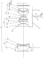
Fig. 1 is a sectional view of a zoom lens of example 1 of the present invention at a wide-angle end.
Fig. 2A is an aberration diagram at the wide-angle end of the zoom lens of example 1.
Fig. 2B is an aberration diagram of the zoom lens of example 1 at an intermediate zoom position.
Fig. 2C is an aberration diagram of the zoom lens of example 1 at the telephoto end.
Fig. 3 is a sectional view of a zoom lens of example 2 of the present invention at a wide-angle end.
Fig. 4A is an aberration diagram at the wide-angle end of the zoom lens of example 2.
Fig. 4B is an aberration diagram of the zoom lens of example 2 at an intermediate zoom position.
Fig. 4C is an aberration diagram of the zoom lens of example 2 at the telephoto end.
Fig. 5 is a sectional view of a zoom lens of example 3 of the present invention at a wide-angle end.
Fig. 6A is an aberration diagram at the wide-angle end of the zoom lens of example 3.
Fig. 6B is an aberration diagram of the zoom lens of example 3 at an intermediate zoom position.
Fig. 6C is an aberration diagram of the zoom lens of example 3 at the telephoto end.
Fig. 7 is a sectional view of a zoom lens of example 4 of the present invention at a wide-angle end.
Fig. 8A is an aberration diagram at the wide-angle end of the zoom lens of example 4.
Fig. 8B is an aberration diagram of the zoom lens of example 4 at an intermediate zoom position.
Fig. 8C is an aberration diagram of the zoom lens of example 4 at the telephoto end.
Fig. 9 is a sectional view of a zoom lens of example 5 of the present invention at a wide-angle end.
Fig. 10A is an aberration diagram at the wide-angle end of the zoom lens of example 5.
Fig. 10B is an aberration diagram of the zoom lens of example 5 at an intermediate zoom position.
Fig. 10C is an aberration diagram of the zoom lens of example 5 at the telephoto end.
Fig. 11 is a sectional view of a zoom lens of example 6 of the present invention at a wide-angle end.
Fig. 12A is an aberration diagram at the wide-angle end of the zoom lens of example 6.
Fig. 12B is an aberration diagram of the zoom lens of example 6 at an intermediate zoom position.
Fig. 12C is an aberration diagram of the zoom lens of example 6 at the telephoto end.
Fig. 13 is a sectional view of a zoom lens of example 7 of the present invention at a wide-angle end.
Fig. 14A is an aberration diagram at the wide-angle end of the zoom lens of example 7.
Fig. 14B is an aberration diagram of the zoom lens of example 7 at an intermediate zoom position.
Fig. 14C is an aberration diagram of the zoom lens of example 7 at the telephoto end.
Fig. 15 is a sectional view of a zoom lens of example 8 of the present invention at a wide-angle end.
Fig. 16A is an aberration diagram at the wide-angle end of the zoom lens of example 8.
Fig. 16B is an aberration diagram of the zoom lens of example 8 at an intermediate zoom position.
Fig. 16C is an aberration diagram of the zoom lens of example 8 at the telephoto end.
Fig. 17 is a sectional view of a zoom lens of example 9 of the present invention at a wide-angle end.
Fig. 18A is an aberration diagram at the wide-angle end of the zoom lens of example 9.
Fig. 18B is an aberration diagram of the zoom lens of example 9 at an intermediate zoom position.
Fig. 18C is an aberration diagram of the zoom lens of example 9 at the telephoto end.
Fig. 19 is a sectional view of a zoom lens of example 10 of the present invention at a wide-angle end.
Fig. 20A is an aberration diagram at the wide-angle end of the zoom lens of example 10.
Fig. 20B is an aberration diagram of the zoom lens of example 10 at an intermediate zoom position.
Fig. 20C is an aberration diagram of the zoom lens of example 10 at the telephoto end.
Fig. 21A is a sectional view of a zoom lens and a ball cover of example 1.
Fig. 21B is a sectional view of a zoom lens and a protective cover of example 1.
Fig. 22A is an illustration of a monitoring camera and an example of use thereof in the embodiment of the present invention.
Fig. 22B is an illustration of a monitoring camera and an example of use thereof in the embodiment of the present invention.
Fig. 23 is an explanatory diagram of a zoom locus of the zoom lens of example 1.
Detailed Description
Exemplary embodiments of the present invention will now be described with reference to the accompanying drawings.
Fig. 1, 3, 5, 7, 9, 11, 13, 15, 17, and 19 are sectional views of zoom lenses of examples 1 to 10 of the present invention at a wide-angle end, respectively. Each sectional view of the zoom lens is a sectional view at the wide-angle end (shortest focal length).
Fig. 2A, 2B, and 2C are aberration diagrams of the zoom lens of example 1 at the wide-angle end, an intermediate zoom position, and a telephoto end (longest focal length), respectively. Fig. 4A, 4B, and 4C are aberration diagrams of the zoom lens of example 2 at the wide-angle end, an intermediate zoom position, and a telephoto end (longest focal length), respectively. Fig. 6A, 6B, and 6C are aberration diagrams of the zoom lens of example 3 at the wide-angle end, an intermediate zoom position, and a telephoto end (longest focal length), respectively. Fig. 8A, 8B, and 8C are aberration diagrams of the zoom lens of example 4 at the wide-angle end, an intermediate zoom position, and a telephoto end (longest focal length), respectively. Fig. 10A, 10B, and 10C are aberration diagrams of the zoom lens of example 5 at the wide-angle end, an intermediate zoom position, and a telephoto end (longest focal length), respectively. Fig. 12A, 12B, and 12C are aberration diagrams of the zoom lens of example 6 at the wide-angle end, an intermediate zoom position, and a telephoto end (longest focal length), respectively. Fig. 14A, 14B, and 14C are aberration diagrams of the zoom lens of example 7 at the wide-angle end, an intermediate zoom position, and a telephoto end (longest focal length), respectively. Fig. 16A, 16B, and 16C are aberration diagrams of the zoom lens of example 8 at the wide-angle end, an intermediate zoom position, and a telephoto end (longest focal length), respectively. Fig. 18A, 18B, and 18C are aberration diagrams of the zoom lens of example 9 at the wide-angle end, an intermediate zoom position, and a telephoto end (longest focal length), respectively. Fig. 20A, 20B, and 20C are aberration diagrams of the zoom lens of example 10 at the wide-angle end, an intermediate zoom position, and a telephoto end (longest focal length), respectively.
Example 1 shows a zoom lens having a zoom ratio of 3.90 and an F-number of 1.75 to 4.09. Example 2 shows a zoom lens having a zoom ratio of 3.90 and an F-number of 1.75 to 4.00. Example 3 shows a zoom lens having a zoom ratio of 3.90 and an F-number of 1.75 to 4.09. Example 4 shows a zoom lens having a zoom ratio of 4.00 and an F-number of 1.75 to 4.30. Example 5 shows a zoom lens having a zoom ratio of 4.00 and an F-number of 1.75 to 4.30. Example 6 shows a zoom lens having a zoom ratio of 3.90 and an F-number of 1.75 to 4.09. Example 7 shows a zoom lens having a zoom ratio of 4.00 and an F-number of 1.75 to 4.20. Example 8 shows a zoom lens having a zoom ratio of 3.30 and an F-number of 1.75 to 4.10. Example 9 shows a zoom lens having a zoom ratio of 6.00 and an F-number of 1.75 to 5.00. Example 10 shows a zoom lens having a zoom ratio of 4.00 and an F-number of 1.75 to 4.30.
Fig. 21A is a schematic diagram of a main portion when a ball cover is attached to a zoom lens according to an embodiment of the present invention. Fig. 21B is a schematic diagram of a main portion when the protective cover is attached to the zoom lens according to the embodiment of the present invention. Fig. 22A and 22B are each a schematic diagram of a main part of a monitoring camera (image pickup apparatus) including a zoom lens according to an embodiment of the present invention. Fig. 23 is an illustration of the movement locus (zoom locus) of each lens unit during zooming of the zoom lens of example 1.
The zoom lens in each example is an image pickup optical system for a monitoring camera. The zoom lens in each example can also be used for an image pickup apparatus such as a video camera, a digital camera, a silver-halide film camera, or a Television (TV) camera.
In the sectional view, the left side is the object side (front), and the right side is the image side (rear). A zoom lens L0 is shown in each cross-sectional view. When the order of the lens units from the object side is denoted by "i", the i-th lens unit is denoted by Li. Also shown are an aperture stop SP and an optical block G (e.g. a filter). When the zoom lens is used as an image pickup optical system of a digital camera, a video camera, or a monitoring camera, the image plane IP corresponds to an image pickup surface of a solid-state image pickup element (photoelectric conversion element) such as a CCD sensor or a CMOS sensor.
In the zoom lens of each example, the interval between each pair of adjacent lens units changes during zooming. Arrows indicate moving loci of the respective lens units during zooming from the wide-angle end to the telephoto end. Similarly, an arrow regarding "focus" indicates a moving direction of the lens unit during focusing from infinity to a close distance.
In the spherical aberration diagram, a solid line "d" indicates a d line (wavelength: 587.6nm), and a two-dot chain line "g" indicates a g line (wavelength: 435.8 nm). In the astigmatism diagram, a dotted line M indicates a meridional image plane of d lines, and a solid line S indicates a sagittal image plane of d lines. The distortion is shown as a value at the d-line. The lateral chromatic aberration is shown as a value at the g-line. The half-view (in degrees) is denoted by "ω" and the F-number is denoted by Fno. In each example, the wide-angle end and the telephoto end refer to zoom positions when the lens unit for varying magnification is positioned at respective ends of a range in which the lens unit is movable on the optical axis. In fig. 2A, 2B, 2C, 8A, 8B, 8C, 14A, 14B, 14C, 16A, 16B, 16C, 18A, 18B, 18C, 20A, 20B and 20C, a C line (wavelength: 656.3nm) and an F line (wavelength: 486.1nm) are also shown. Specifically, in the spherical aberration diagram and the lateral chromatic aberration diagram, a chain line C indicates a line C, and a broken line F indicates a line F.
The zoom lens of each example includes, in order from the object side to the image side, a first lens unit L1, a second lens unit L2, a third lens unit L3, and a fourth lens unit L4 having a negative refractive power. The zoom lens may further include a fifth lens unit L5 disposed adjacent to the image side of the fourth lens unit L4. At least one lens unit may be further disposed on the image side of the fifth lens unit L5.
In each example, the aperture stop SP is disposed on the object side of the second lens unit L2, and is configured to move along the same locus as that of the second lens unit L2 during zooming. The aperture diameter of the aperture stop SP may be constant during zooming, or may be changed during zooming. When the aperture diameter of the aperture stop SP is changed, lower ray coma (lower ray coma flare) mainly caused by the off-axis light beam at the telephoto end can be cut (cut), so that more satisfactory optical performance can be obtained.
First, examples 1 to 5 are described.
Examples 1 to 3 represent a four-unit zoom lens. The four-unit zoom lens includes, from the object side to the image side, a first lens unit L1 having a negative refractive power, a second lens unit L2 having a positive refractive power, a third lens unit L3 having a negative refractive power, and a fourth lens unit L4 having a positive refractive power. The first lens unit L1 is configured not to move during zooming, and the second lens unit L2, the third lens unit L3, and the fourth lens unit L4 are configured to move along a locus indicated by an arrow during zooming.
Examples 4 and 5 represent a five-unit zoom lens. The five-unit zoom lens includes, from the object side to the image side, a first lens unit L1 having a negative refractive power, a second lens unit L2 having a positive refractive power, a third lens unit L3 having a negative refractive power, a fourth lens unit L4 having a positive refractive power, and a fifth lens unit L5 having a negative refractive power. The first lens unit L1 is configured not to move during zooming, and the second lens unit L2, the third lens unit L3, the fourth lens unit L4, and the fifth lens unit L5 are configured to move along a trajectory indicated by an arrow during zooming.
The third lens unit L3 or the fourth lens unit L4 is responsible for focusing. In examples 1, 2, 4, and 5, focusing is performed by moving the third lens unit L3 on the optical axis. When focusing is to be performed from infinity to a close distance at the telephoto end, the third lens unit L3 recedes toward the image side as indicated by an arrow 3c in the sectional view.
A curve 3a in the figure indicates a movement locus for correcting an image plane variation accompanying zooming from the wide-angle end to the telephoto end when the focus is at infinity. A curve 3b indicates a movement locus for correcting an image plane variation accompanying zooming from the wide-angle end to the telephoto end when the focus is at a close distance.
In example 3, the fourth lens unit L4 is moved to correct an image plane variation accompanying magnification variation and perform focusing. A solid-line curve 4a and a broken-line curve 4b associated with the fourth lens unit L4 are movement loci for correcting an image plane variation accompanying magnification variation when the focal point is at infinity and close distance, respectively. Further, focusing from infinity to a close distance is performed by advancing the fourth lens unit L4 as indicated by arrow 4C. Focusing may be performed by moving a part or all of the lenses of the second lens unit L2 on the optical axis instead of the third lens unit L3 or the fourth lens unit L4.
Describing a method of moving each lens unit during zooming with reference to fig. 23, fig. 23 is a sectional view of the four-unit zoom lens of example 1 at the wide-angle end, an intermediate zoom position, and a telephoto end. During zooming from the wide-angle end to the telephoto end, the second lens unit L2, the third lens unit L3, and the fourth lens unit L4 independently move (along different trajectories) as indicated by arrows.
Specifically, the second lens unit L2 is configured to be monotonously moved from the image side toward the object side to perform magnification variation. The third lens unit L3 is configured to move simultaneously along a locus convex toward the object side. That is, the third lens unit L3 is configured to move toward the object side, and then move toward the image side. The fourth lens unit L4 is configured to move along a trajectory having at least one inflection point. To form such a movement locus of the lens units, at the wide-angle end, the interval between each pair of lens units of the second lens unit L2, the third lens unit L3, and the fourth lens unit L4 is appropriately fixed, so that the zoom ratio can be easily increased. Further, the first lens unit L1 is formed to have a negative refractive power, so that the angle of view can be easily increased.
The first lens unit L1 of the zoom lens having a wide angle of view has a large effective diameter, and thus the weight increases. Therefore, it is difficult for the first lens unit L1 to perform quick following during zooming. In each example, a configuration is adopted in which the lens of the second lens unit L2 and subsequent lenses having a small weight are driven during zooming in order to facilitate quick zooming.
It is important to reduce variations in optical performance due to focusing and to reduce variations in incident angles of off-axis rays to an image pickup element during zooming while coping with size increases of the image pickup element. Therefore, in each example, the configuration of the third lens unit L3 and the fourth lens unit L4, the refractive power, and the interval between the third lens unit L3 and the fourth lens unit L4 at the telephoto end are defined.
In addition, variation in optical performance due to focusing is reduced, and variation in the incident angle of off-axis light rays to the image pickup element during zooming is reduced. Thus, each lens unit is configured as described above.
Further, the third lens unit L3 is constituted by a single optical element. The single optical element herein includes not only a single lens but also a cemented lens obtained by cementing a plurality of lenses to each other. The fourth lens unit L4 includes a plurality of lenses arranged at intervals. A focal length of the third lens unit L3 is denoted by f3, a focal length of the fourth lens unit L4 is denoted by f4, and an interval between the third lens unit L3 and the fourth lens unit L4 at the telephoto end is denoted by L34 t. At this time, the following conditional expression is satisfied.
0.8<|f3/f4|<3.0···(1)
2.5<|f3/L34t|<5.0···(2)
Next, the technical meaning of each of the conditional expressions given above is described.
Conditional expression (1) defines a ratio between the refractive power of the third lens unit L3 and the refractive power of the fourth lens unit L4. The conditional expression (1) is an expression for reducing a variation in optical performance due to focusing. When the ratio exceeds the upper limit of conditional expression (1) and the positive refractive power of the fourth lens unit L4 increases, the angle variation of off-axis rays due to the fourth lens unit L4 increases, and the variation of the incident angle of off-axis rays to the image pickup element during zooming disadvantageously increases.
When the ratio is below the lower limit of conditional expression (1) and the negative refractive power of the third lens unit L3 increases (the absolute value of the negative refractive power increases), the variation in optical performance during focusing increases, and in particular, the variation in field curvature and astigmatism at the wide-angle end disadvantageously increases.
Conditional expression (2) defines a ratio between the negative refractive power of the third lens unit L3 and the interval between the third lens unit L3 and the fourth lens unit L4 at the telephoto end. Conditional expression (2) is an expression for coping with an increase in size of the image pickup element. At the telephoto end where the focal length of the entire system of the zoom lens is increased, the off-axis light beam is caused to diverge by the third lens unit L3 having a negative refractive power. In this way, the incident height of the light is effectively increased, and an image pickup element of increased size is coped with.
When the ratio exceeds the upper limit of conditional expression (2) and the interval between the third lens unit L3 and the fourth lens unit L4 at the telephoto end is decreased, the effect of increasing the incident height of the off-axis light beam by the third lens unit L3 becomes disadvantageously insufficient. When the ratio is below the lower limit of conditional expression (2) and the negative refractive power of the third lens unit L3 is increased, the image height can be easily increased (the image pickup plane can be easily increased), but the variation in curvature of field and astigmatism due to focusing at the wide-angle end is disadvantageously increased.
In each example, the numerical ranges of conditional expressions (1) and (2) are preferably set as follows.
1.0<|f3/f4|<2.5···(1a)
2.8<|f3/L34t|<4.5···(2a)
More preferably, the numerical ranges of the conditional expressions (1a) and (2a) are set as follows.
1.1<|f3/f4|<2.2···(1b)
3.0<|f3/L34t|<4.2···(2b)
With the above configuration, a zoom lens is obtained in which variation in optical performance due to focusing is reduced while coping with an increase in size of the image pickup element, and variation in incident angle of off-axis light rays to the image pickup element during zooming is reduced.
Further, in each example, the fourth lens unit L4 includes at least two positive lenses and at least one negative lens. The lens surface of the fourth lens unit L4 closest to the object side has a shape convex toward the object side. Among the lenses arranged at intervals in the fourth lens unit L4, the image side lens surface R4a of the lens 4a on the object side has a shape concave toward the image side, and the object side lens surface R4b of the lens 4b on the image side has a shape convex toward the object side. The absolute value of the radius of curvature of the lens surface R4a is smaller than the absolute value of the radius of curvature of the lens surface R4 b.
The fourth lens unit L4 having a positive refractive power has the following effects: the off-axis light beam caused to diverge by the third lens unit L3 having a negative refractive power is converged, appropriately collects the light rays onto the surface of the image pickup element and guides the light rays to form an image. That is, in the zoom lens of each example, the lens configuration of the fourth lens unit L4 is important to appropriately correct the aberration of the off-axis light beam.
In view of this, the fourth lens unit L4 is constituted by a plurality of lenses including at least two positive lenses and at least one negative lens, so that various aberrations, mainly astigmatism and chromatic aberration, are appropriately corrected. Further, in order to facilitate control of the incident angle of the off-axis light beam caused to diverge to the surface of the image pickup element by the third lens unit L3, the lens surface of the fourth lens unit L4 closest to the object side is convex toward the object side.
Further, as the shape of the air lens formed by the lens surfaces of the object side and the image side of the fourth lens unit L4 (which correspond to the interval formed in the lens units), the lens surface of the object side has a shape concave toward the image side, and the lens surface of the image side has a shape convex toward the object side. Further, the absolute value of the radius of curvature of the lens surface on the object side is smaller than the absolute value of the radius of curvature of the lens surface on the image side.
With such a configuration, a meniscus air lens having a convex surface directed to the object side is formed in the fourth lens unit L4. An air lens having such a shape is formed in the fourth lens unit L4 that the variation in the incident angle of off-axis rays to the image pickup element during zooming is reduced while astigmatism and coma aberration caused by the off-axis beams are appropriately corrected.
The third lens unit L3 is configured to move along a locus convex toward the object side during zooming from the wide angle end to the telephoto end, and is positioned at the object side at the telephoto end compared to the position at the wide angle end. The second lens unit L2 is configured to move from the image side toward the object side during zooming from the wide-angle end to the telephoto end.
In view of this, with the space formed when the second lens unit L2 is moved from the image side toward the object side, the third lens unit L3 is moved to draw a locus convex toward the object side. In this way, by effectively utilizing the space in the optical system, the entire lens length is reduced. Further, the third lens unit L3 is configured to move so as to be positioned on the object side at the telephoto end compared to the position at the wide angle end. By this movement, at the telephoto end where the focal length of the entire system of the zoom lens increases, the third lens unit L3 having a negative refractive power disperses the off-axis light beam. In this way, the incident height of the light is effectively increased, and thus the image pickup element having an increased size is coped with.
The second lens unit L2 has an aspherical surface, and includes a positive lens disposed closest to the object side. The second lens unit L2 includes a plurality of lenses arranged at intervals. Among the lenses arranged at intervals of the second lens unit L2, the image side lens surface R2a of the lens 2a on the object side has a shape concave toward the image side, and the object side lens surface R2b of the lens 2b on the image side has a shape convex toward the object side. The absolute value of the radius of curvature of the lens surface R2a is smaller than the absolute value of the radius of curvature of the lens surface R2 b.
With such a configuration, a meniscus air lens having a convex surface directed to the object side is formed in the second lens unit L2. The second lens unit L2 having a positive refractive power converges the axial light beam caused to diverge by the first lens unit L1 having a negative refractive power, and enters the converged light beam into the third lens unit L3.
The second lens unit L2 has an aspherical surface and includes a positive lens disposed closest to the object side so that spherical aberration occurring when the axial light beam converges is appropriately corrected. Further, an air lens having the above-described shape is formed in the second lens unit L2 so that curvature of field and astigmatism are appropriately corrected. Further, in each example, preferably, at least one of the following conditional expressions is satisfied.
The focal length of the first lens unit L1 is denoted by f 1. A distance (lens unit thickness) from the lens surface closest to the object side to the lens surface closest to the image side of the fourth lens unit L4 is denoted by D4. A distance (lens unit thickness) from the lens surface closest to the object side to the lens surface closest to the image side of the first lens unit L1 is denoted by D1.
At this time, it is preferable that at least one of the following conditional expressions is satisfied.
1.5<f4/L34t<5.0···(3)
1.5<f3/f1<3.0···(4)
1.0<|f4/f1|<2.0···(5)
2.0<f4/D4<4.0···(6)
1.0<|f1/D1|<2.0···(7)
Next, the technical meaning of each of the conditional expressions given above is described.
Conditional expression (3) defines a ratio between the refractive power of the fourth lens unit L4 and the interval between the third lens unit L3 and the fourth lens unit L4 at the telephoto end. Conditional expression (3) is an expression for reducing variation in the incident angle of the off-axis light beam to the surface of the image pickup element while coping with an image pickup element of increased size. When the ratio exceeds the upper limit of conditional expression (3) and the interval between the third lens unit L3 and the fourth lens unit L4 at the telephoto end decreases, the effect of increasing the incident height of the off-axis light beam by the third lens unit L3 becomes disadvantageously insufficient.
When the ratio is below the lower limit of conditional expression (3) and the positive refractive power of the fourth lens unit L4 increases, the angular variation of off-axis light rays passing through the fourth lens unit L4 increases, and it becomes difficult to reduce the variation of the incident angle of off-axis light rays to the image pickup element during zooming.
Conditional expression (4) defines the ratio between the refractive power of the third lens unit L3 and the refractive power of the first lens unit L1. When the ratio exceeds the upper limit of conditional expression (4) and the negative refractive power of the first lens unit L1 excessively increases, the correction of distortion and field curvature at the wide-angle end becomes disadvantageously insufficient. When the ratio is below the lower limit of conditional expression (4) and the negative refractive power of the third lens unit L3 excessively increases, the variation in optical performance due to focusing, particularly the variation in field curvature and astigmatism at the wide-angle end, disadvantageously increases.
Conditional expression (5) defines the ratio between the positive refractive power of the fourth lens unit L4 and the negative refractive power of the first lens unit L1. When the ratio exceeds the upper limit of conditional expression (5) and the negative refractive power of the first lens unit L1 excessively increases, the correction of distortion and field curvature at the wide-angle end becomes disadvantageously insufficient. When the ratio is below the lower limit of conditional expression (5) and the positive refractive power of the fourth lens unit L4 excessively increases, the angular variation of off-axis light rays caused by the fourth lens unit L4 increases, and it becomes difficult to reduce the variation of the incident angle of off-axis light rays to the image pickup element during zooming.
Conditional expression (6) defines the ratio between the positive refractive power of the fourth lens unit L4 and the lens unit thickness of the fourth lens unit L4 in the optical axis direction. When the ratio exceeds the upper limit of conditional expression (6) and the positive refractive power of the fourth lens unit L4 is excessively reduced, it becomes disadvantageously difficult to control the incident angle of the off-axis light beam caused to diverge by the third lens unit L3 to the surface of the image pickup element. When the ratio is below the lower limit of conditional expression (6) and the lens unit thickness of the fourth lens unit L4 in the optical axis direction is excessively increased, it becomes difficult to reduce the entire lens length.
Conditional expression (7) defines the ratio between the negative refractive power of the first lens unit L1 and the lens unit thickness of the first lens unit L1 in the optical axis direction. When the ratio exceeds the upper limit of conditional expression (7) and the negative refractive power of the first lens unit L1 decreases (the absolute value of the negative refractive power decreases), it becomes difficult to secure a wide image pickup angle of view at the wide-angle end. When the ratio is below the lower limit of conditional expression (7) and the lens unit thickness of the first lens unit L1 in the optical axis direction is increased, it becomes difficult to reduce the entire lens length. Further, the effective diameter of the lens closest to the object side in the entire system of the zoom lens increases, and the entire system size of the zoom lens increases.
In each example, in order to correct aberrations, the numerical ranges of conditional expressions (3) to (7) are more preferably set as follows.
1.7<f4/L34t<4.0···(3a)
1.7<f3/f1<2.8···(4a)
1.1<|f4/f1|<1.8···(5a)
2.2<f4/D4<3.5···(6a)
1.1<|f1/D1|<1.7···(7a)
In each example, it is still more preferable to set the numerical range of conditional expressions (3a) to (7a) as follows.
1.9<f4/L34t<3.2···(3b)
1.8<f3/f1<2.7···(4b)
1.2<|f4/f1|<1.7···(5b)
2.4<f4/D4<3.2···(6b)
1.2<|f1/D1|<1.5···(7b)
Next, examples 1, 2, 3, and 6 are described.
Each exemplary zoom lens is composed of the following lenses arranged in order from the object side to the image side: a first lens unit L1 having a negative refractive power, a second lens unit L2 having a positive refractive power, a third lens unit L3 having a negative refractive power, and a fourth lens unit L4 having a positive refractive power. The first lens unit L1 is configured not to move during zooming, and the second lens unit L2 to the fourth lens unit L4 are configured to move during zooming.
The zoom lens of each example has a four-unit configuration, which is a configuration suitable for obtaining high optical performance in the entire zoom range from the wide-angle end to the telephoto end while achieving downsizing of the entire system of the zoom lens and a small F-number. Further, the first lens unit L1 has a negative refractive power, and therefore the angle of view can be easily increased.
In each example, the fourth lens unit L4 includes at least two lenses. The focal length of the second lens unit L2 is denoted by f2, and the focal length of the entire system of the zoom lens at the wide-angle end is denoted by "fw". A moving amount of the second lens unit L2 during zooming from the wide-angle end to the telephoto end is denoted by M2, and a moving amount of the fourth lens unit L4 during zooming from the wide-angle end to the telephoto end is denoted by M4. At this time, the following conditional expression is satisfied.
1.0<f2/fw<3.5···(8)
-20.0<M2/M4<-5.0···(9)
In this case, the movement amount of the lens unit during zooming from the wide-angle end to the telephoto end refers to a difference between the position of the lens unit on the optical axis at the wide-angle end and the position of the lens unit on the optical axis at the telephoto end. The sign of the movement amount is positive when the lens unit is positioned on the image side at the telephoto end as compared with the position at the wide angle end, and the sign of the movement amount is negative when the lens unit is positioned on the object side at the telephoto end as compared with the position at the wide angle end.
Next, the technical meaning of each of the conditional expressions given above is described. Conditional expression (8) is an expression for obtaining a high zoom ratio while reducing the size of the entire system of the zoom lens. When the ratio exceeds the upper limit of conditional expression (8), the positive power (refractive power) of the second lens unit L2 excessively decreases, and the movement amount for obtaining a desired zoom ratio increases. Therefore, it becomes difficult to downsize the entire system of the zoom lens.
When the ratio is below the lower limit of conditional expression (8), the positive power of the second lens unit L2 excessively increases, and spherical aberration increases with an increase in aperture ratio (to obtain small Fno). Therefore, it becomes difficult to obtain high resolution.
Conditional expression (9) is an expression for appropriately setting the relationship between the movement amounts of the second lens unit L2 and the fourth lens unit L4 configured to function as magnification-varying lens units during zooming. The second lens unit L2 functions as a main magnification lens unit. The second lens unit L2 is configured to move from the image side toward the object side during zooming from the wide-angle end to the telephoto end to obtain a magnification varying effect.
Further, the fourth lens unit L4 is configured to move from the object side toward the image side during zooming from the wide-angle end to the telephoto end to ensure a magnification-varying ratio. That is, both the second lens unit L2 and the fourth lens unit L4 with which the magnification varying effect is easily obtained are driven simultaneously, so that the magnification varying ratio is effectively obtained.
When the ratio exceeds the upper limit of conditional expression (9), the moving amount of the fourth lens unit L4 excessively increases, and it becomes difficult to ensure a back focal length of a predetermined length at the telephoto end. Therefore, the entire lens length increases, and it becomes difficult to downsize the entire system of the zoom lens. When the ratio is below the lower limit of conditional expression (9), the moving amount of the fourth lens unit L4 decreases, and it becomes difficult to obtain a sufficient magnification-varying effect. Therefore, it becomes difficult to increase the zoom ratio.
Preferably, the numerical ranges of conditional expressions (8) and (9) are set as follows.
1.5<f2/fw<3.2···(8a)
-15.0<M2/M4<-6.0···(9a)
In each example, preferably, at least one of the following conditional expressions is satisfied. The fourth lens unit L4 is composed of a positive lens, a negative lens, and a positive lens arranged in order from the object side to the image side. A focal length of the positive lens G4b disposed closest to the image side of the fourth lens unit L4 is denoted by f4p, and a focal length of the fourth lens unit L4 is denoted by f 4. A difference of the lens unit interval between the third lens unit L3 and the fourth lens unit L4 at the wide-angle end and the telephoto end is denoted by D34wt, and a focal length of the third lens unit L3 is denoted by f 3.
The positive lens G4b disposed closest to the image side of the fourth lens unit L4 and the lens G4a adjacent to the object side of the positive lens G4b are disposed at an interval. A radius of curvature of the lens surface on the image side of the lens G4a is represented by Ra, and a radius of curvature of the lens surface on the object side of the positive lens G4b is represented by Rb. The third lens unit L3 is configured by one negative lens, and the third lens unit L3 is configured to move along a locus convex toward the object side during zooming from the wide-angle end to the telephoto end. The abbe number of the material of the negative lens included in the third lens unit L3 is denoted by ν 3 d.
The second lens unit L2 includes, in order from the object side to the image side, a positive lens having an aspherical surface and a first cemented lens adjacent to the positive lens and obtained by cementing the positive lens and the negative lens to each other in order from the image side. The positive lens and the negative lens are made of different materials from each other. The second lens unit L2 further includes a second cemented lens obtained by cementing a negative lens and a positive lens to each other. The negative lens and the positive lens are made of different materials from each other. The focal length of the first cemented lens is denoted by f2a, and the focal length of the second cemented lens is denoted by f2 b.
When the zoom lens of each example is used in an image pickup apparatus including an image pickup element, the maximum value of the half angle of view at the wide-angle end is represented by "ω w", and the maximum value of the half angle of view at the telephoto end is represented by "ω t". The lateral magnification of the second lens unit L2 at the wide-angle end is denoted by β 2w, and the lateral magnification of the second lens unit L2 at the telephoto end is denoted by β 2 t.
At this time, at least one of the following conditional expressions is preferably satisfied.
0.65<f4p/f4<1.30···(10)
0.45<f2/f4<1.00···(11)
-7.0<f3/D34wt<-3.0···(12)
-0.40<(Ra-Rb)/(Ra+Rb)<-0.05···(13)
73<ν3d<100···(14)
0.00≤|f2b/f2a|<0.60···(15)
0.60<(tanωw/tanωt)/(β2t/β2w)<0.90···(16)
Next, the technical meaning of each of the conditional expressions given above is described. Conditional expression (10) defines the optical power of the positive lens G4b forming the fourth lens unit L4. In this case, the fourth lens unit L4 is configured to satisfactorily correct distortion in the entire zoom range by appropriately defining the optical power of the positive lens G4b closest to the image side while performing aberration correction.
When the ratio exceeds the upper limit of conditional expression (10), the focal length of the positive lens G4b closest to the image side increases (i.e., the optical power decreases), and therefore the distortion disadvantageously greatly increases in the positive direction. When the ratio is below the lower limit of conditional expression (10), the power of the positive lens G4b closest to the image side increases, and therefore the distortion disadvantageously greatly increases in the negative direction.
Conditional expression (11) defines a ratio between the optical power of the second lens unit L2 and the optical power of the fourth lens unit L4. The second lens unit L2 and the fourth lens unit L4 are two variable power lens units. When the ratio exceeds the upper limit of conditional expression (11), the focal length of the second lens unit L2 increases, and the positive power decreases. Therefore, the amount of movement of the second lens unit L2 needs to be increased for magnification variation, and it becomes difficult to downsize the entire system of the zoom lens. When the ratio is below the lower limit of conditional expression (11), the positive power of the second lens unit L2 excessively increases, and various aberrations, in particular, spherical aberration increases. Therefore, the optical performance when the F number is reduced is lowered.
Conditional expression (12) defines the relationship between the movement amounts of the third lens unit L3 and the fourth lens unit L4 during zooming. The interval difference D34wt represents a positional difference of the third lens unit L3 and the fourth lens unit L4 at the wide-angle end and the telephoto end. The third lens unit L3 is a movable lens unit having the role of a focus lens unit, and the fourth lens unit L4 is a variable power lens unit. Therefore, the light is required to pass through both the third lens unit L3 and the fourth lens unit L4 made of a glass material to have an outer diameter as small as possible.
When the ratio exceeds the upper limit of conditional expression (12), the third lens unit L3 and the fourth lens unit L4 move along a locus with a large movement amount. In this case, the light is bounced back by the third lens unit L3 having a negative refractive power, and thus when the light enters the fourth lens unit L4, the light diameter needs to be increased. Therefore, it becomes difficult to downsize the entire system of the zoom lens. When the ratio is lower than the lower limit of conditional expression (12), it becomes difficult to sufficiently ensure the moving amounts of the third lens unit L3 and the fourth lens unit L4, and the power of each lens unit needs to be increased. Therefore, curvature of field and lateral chromatic aberration are disadvantageously increased.
Conditional expression (13) is an expression for satisfactorily correcting especially coma aberration using the effect as the air lens positioned closest to the image side of the fourth lens unit L4. When the ratio exceeds the upper limit of conditional expression (13), the power as an air lens becomes insufficient, and the effect of correcting various aberrations decreases. When the ratio is below the lower limit of conditional expression (13), the power as an air lens is excessively increased, and various aberrations are disadvantageously excessively corrected.
Conditional expression (14) defines the material forming the negative lens of the third lens unit L3 serving as a focus lens unit. In order to suppress the variation of chromatic aberration during focusing from a short distance to a long distance, it is preferable to use a material having dispersion (dispersion) as low as possible. Further, in order to achieve quick focusing and downsizing, it is preferable that the third lens unit L3 is composed of one lens. When the value exceeds the upper limit of conditional expression (14), the amount of the material satisfying the above condition is disadvantageously reduced. When the value is below the lower limit of conditional expression (14), chromatic aberration increases, and variation in lateral chromatic aberration during focusing increases.
Conditional expression (15) defines the refractive powers of the two cemented lenses included in the second lens unit L2. In each cemented lens, a positive lens and a negative lens made of materials different from each other are cemented to each other, so that the cemented lens can have an effect of correcting chromatic aberration. Further, when a plurality of materials are used without securing the interval, chromatic aberration can be corrected while reducing the size of the zoom lens.
In each example, attention is paid to this effect, and at least two cemented lenses are employed to correct chromatic aberration in the second lens unit L2 having a wide F-number (Fno) beam. The power of these cemented lenses is set appropriately.
When the ratio exceeds the upper limit of conditional expression (15), the refractive power of the first cemented lens may increase. In this case, the Fno beam of the first cemented lens is increased compared to the second cemented lens. Therefore, the first cemented lens is more susceptible to the influence of the optical power, and the spherical aberration disadvantageously increases. The lower limit of conditional expression (15) means that the power of the first cemented lens is infinity (no optical power). Even when the lens unit has no power, the power at the cemented lens surface can be ensured when different glass materials are used. Therefore, chromatic aberration can be easily corrected.
The positive and negative lenses forming the cemented lens may be arranged in any order. Further, the cemented lens is not limited to two lenses cemented with each other, and may be three lenses cemented with each other.
Conditional expression (16) defines the variation relationship of the image pickup angle of view during magnification variation of the second lens unit L2 serving as the main magnification lens unit. The image pickup angle of view "ω w" at the wide-angle end and the image pickup angle of view "ω t" at the telephoto end are angles of view indicating a range in which image pickup is allowed to include distortion. When the ratio exceeds the upper limit of conditional expression (16), distortion at the wide-angle end increases, and deformation and compression of the shape of the object after image pickup disadvantageously increase. When the ratio is lower than the lower limit of conditional expression (16), it becomes difficult to obtain a change in angle of view (an increase in zoom ratio) due to zooming.
It is more preferable to set the numerical ranges of conditional expressions (10) to (16) as follows.
0.78<f4p/f4<1.10...(10a)
0.60<f2/f4<0.90···(11a)
-6.2<f3/D34wt<-3.8···(12a)
-0.30<(Ra-Rb)/(Ra+Rb)<-0.10...(13a)
80<ν3d<96···(14a)
0.02≤|f2b/f2a|<0.45···(15a)
0.68<(tanωw/tanωt)/(β2t/β2w)<0.85···(16a)
As described above, according to each example, the following zoom lens can be obtained: has a half angle of view of 40 degrees or more, a zoom ratio of 3 or more, and an F-number at a wide-angle end of less than 2.0, and is capable of sufficiently supporting an image pickup element having a pixel number for 4K. An image pickup apparatus including the zoom lens can also be obtained.
Next, examples 1, 4, and 7 to 10 are described.
Examples 1 and 7 to 9 are each a four-unit configuration zoom lens. The four-unit configuration zoom lens is composed of the following lenses arranged in order from the object side to the image side: a first lens unit L1 having a negative refractive power, a second lens unit L2 having a positive refractive power, a third lens unit L3 having a negative refractive power, and a fourth lens unit L4 having a positive refractive power. The first lens unit L1 is configured not to move during zooming. The second lens unit L2, the third lens unit L3, and the fourth lens unit L4 are configured to move independently along different trajectories from each other as indicated by arrows during zooming.
Examples 4 and 10 are each a five-unit configuration zoom lens. The five-unit configuration zoom lens is composed of the following lenses arranged in order from the object side to the image side: a first lens unit L1 having a negative refractive power, a second lens unit L2 having a positive refractive power, a third lens unit L3 having a negative refractive power, a fourth lens unit L4 having a positive refractive power, and a fifth lens unit L5 having a negative refractive power.
The first lens unit L1 is configured not to move during zooming. The second lens unit L2, the third lens unit L3, and the fourth lens unit L4 are configured to move independently along different trajectories from each other as indicated by arrows during zooming. The fifth lens unit L5 is configured not to move or move.
In each example, the aperture stop SP is disposed on the object side of the second lens unit L2, and is configured to move along the same locus as that of the second lens unit L2 during zooming. The aperture of the aperture stop SP may be constant during zooming, or may be changed during zooming.
When the aperture of the aperture stop SP is changed, lower beam coma mainly caused by the off-axis beam at the telephoto end can be cut, and thus more satisfactory optical performance can be obtained. Focusing is performed by moving the third lens unit L3 on the optical axis. When focusing from infinity to a close distance is to be performed at the telephoto end, the third lens unit L3 recedes toward the image side as indicated by an arrow 3c in the lens sectional view.
A curve 3a in the figure indicates a movement locus for correcting an image plane variation accompanying zooming from the wide-angle end to the telephoto end when the focus is at infinity. A curve 3b indicates a movement locus for correcting an image plane variation accompanying zooming from the wide-angle end to the telephoto end when the focus is at a close distance. Focusing may be performed by moving part or all of the lenses of the second lens unit L2 or part or all of the lenses of the fourth lens unit L4 on the optical axis instead of the third lens unit L3.
When a change in chromatic aberration occurs during zooming, it becomes difficult to correct chromatic aberration in the entire zoom range. Therefore, in each example, the material to be used for the movable lens unit is appropriately set so as to correct chromatic aberration during zooming.
The zoom lens of each example includes, in order from the object side: a first lens unit L1 and at least three lens units subsequent to the first lens unit L1, the first lens unit L1 having a negative refractive power and being configured not to move during zooming, specifically, a second lens unit L2, a third lens unit L3, and a fourth lens unit L4 configured to move during zooming.
Each of the second lens unit L2, the third lens unit L3, and the fourth lens unit L4 includes at least one lens "α" made of a material satisfying the following conditional expression.
65<νd<100...(17)
0.52<θgF<0.56···(18)
Wherein "vd" represents the abbe number of the material, and θ gF represents the partial dispersion ratio of the material.
Next, the technical meaning of each of the conditional expressions given above is described.
Conditional expression (17) defines the abbe number of the material of each movable lens unit, and is an expression for reducing variation in chromatic aberration during zooming. When the value is below the lower limit of conditional expression (17), the variation in chromatic aberration during zooming disadvantageously increases. When the value exceeds the upper limit of conditional expression (17), the color difference is disadvantageously excessively corrected.
Conditional expression (18) defines a partial dispersion ratio of a material of each movable lens unit, and is an expression for reducing a variation in chromatic aberration at a plurality of wavelengths during zooming. Conditional expression (18) defines the numerical range of the anomalous partial dispersion material of the movable lens unit. When chromatic aberration is to be corrected in a wide wavelength band, the chromatic aberration remains unchanged for wavelengths other than the specific two wavelengths in many cases. In each example, to reduce this remaining chromatic aberration (18 th order spectrum), an anomalous partial dispersion material was used.
Generally, in many optical materials, a substantially linear relationship is established between the partial dispersion ratio and the abbe number. Meanwhile, a material at a position deviating from the linear relationship is called an anomalous partial dispersion material, which is generally used when the secondary spectrum is to be reduced. The abbe number "vd" and the partial dispersion ratio θ gF of the material are shown below.
νd=(nd-1)/(nF-nC)
θgF=(ng-nF)/(nF-nC)
In this case, nF, nd, nC, and ng respectively represent refractive indices at an F line (486.1nm), a d line (587.6nm), a C line (656.3nm), and a g line (435.8nm) of Fraunhofer line.
When the value exceeds the upper limit of conditional expression (18), the variation of the secondary spectrum of the chromatic aberration during zooming is excessively corrected. When the value is below the lower limit of conditional expression (18), the variation of the secondary spectrum of the chromatic aberration during zooming becomes insufficient.
It is more preferable to set the numerical ranges of conditional expressions (17) and (18) as follows.
70<νd<96...(17a)
0.53<θgF<0.55...(18a)
The sign of the refractive power of the lens "α" included in each of the second lens unit L2, the third lens unit L3, and the fourth lens unit L4 and made of a material satisfying the conditional expressions (17) and (18) is the same as the sign of the refractive power of the lens unit including the lens "α". In this case, the refractive power (optical power) refers to the reciprocal of the focal length, and increases as the focal length decreases. The sign of the refractive power of the lens "α" included in the lens units having a positive refractive power (the second lens unit L2 and the fourth lens unit L4) and made of a material that satisfies the conditional expressions (17) and (18) is positive.
The lens responsible for the positive refractive power of the lens unit having the positive refractive power is a positive lens. When an anomalous partial dispersion material is used for the positive lens, the variation in chromatic aberration at a plurality of wavelengths during zooming is effectively reduced.
The sign of the refractive power of a lens "α" included in the lens unit having a negative refractive power (third lens unit L3) and made of a material that satisfies conditional expressions (17) and (18) is negative. The lens responsible for the negative refractive power of the lens unit having the negative refractive power is a negative lens. When an anomalous partial dispersion material is used for the negative lens, the variation in chromatic aberration at a plurality of wavelengths during zooming is effectively reduced.
In each example, the first lens unit L1 has a relatively large weight, and thus the first lens unit L1 is configured not to move during zooming, so as to facilitate followability during zooming. The second lens unit L2 is configured to move as a main variable power lens unit from the image side toward the object side during zooming from the wide-angle end to the telephoto end to obtain a high variable power effect.
The third lens unit L3 is configured to move along a locus convex toward the object side. The third lens unit L3 also has a function as a focus lens unit. In order to obtain high followability of the third lens unit L3 during focusing, it is desirable to downsize the entire system of the zoom lens. From the viewpoint of weight reduction, it is desirable that the third lens unit L3 be a single optical element. In this case, the optical element refers to a single lens or a cemented lens.
Further, the fourth lens unit L4 is configured to move from the object side toward the image side to ensure the magnification ratio. That is, the second lens unit L2 and the fourth lens unit L4, which are lens units responsible for the variable magnification effect, are simultaneously driven to effectively obtain the variable magnification ratio.
Next, in each example, at least one of the following conditional expressions is preferably satisfied. The focal length of the second lens unit L2 is denoted by f2, and the focal length of the entire system of the zoom lens at the wide-angle end is denoted by "fw". The focal length of the third lens unit L3 is denoted by f 3. The focal length of the fourth lens unit L4 is denoted by f 4. The second lens unit L2 includes at least one positive lens, and the focal length of one positive lens (lens "α") included in the second lens unit L2 is denoted by f2 p.
The third lens unit L3 includes at least one negative lens, and the focal length of one negative lens (lens "α") included in the third lens unit L3 is denoted by f3 n. The fourth lens unit L4 includes at least one positive lens, and the focal length of one positive lens (lens "α") included in the fourth lens unit L4 is denoted by f4 p. The lateral magnification of the second lens unit L2 at the wide-angle end is denoted by β 2w, and the lateral magnification of the second lens unit L2 at the telephoto end is denoted by β 2 t.
At this time, at least one of the following conditional expressions is preferably satisfied.
-5.5<f3/fw<-1.0···(19)
2.0<f4/fw<5.0···(20)
0.4<f2p/f2<2.0···(21)
0.5<f3n/f3<2.0···(22)
0.4<f4p/f4<2.0···(23)
2.0<β2t/β2w<6.0···(24)
Conditional expression (19) defines the focal length of third lens unit L3. Conditional expression (19) is an expression for reducing variation in axial chromatic aberration during zooming. When the ratio exceeds the upper limit of conditional expression (19) and the negative refractive power of the third lens unit L3 increases relative to the focal length of the entire system of the zoom lens at the wide-angle end (the absolute value of the negative refractive power increases), the variation in chromatic aberration during zooming and focusing disadvantageously increases.
When the ratio is below the lower limit of conditional expression (19) and the negative refractive power of the third lens unit L3 is decreased (the absolute value of the negative refractive power is decreased) with respect to the focal length of the entire system of the zoom lens at the wide-angle end, the amount of movement of the third lens unit L3 is increased during zooming and focusing, and therefore the entire lens length is disadvantageously increased.
Conditional expression (20) defines the focal length of the fourth lens unit L4. Conditional expression (20) is an expression for reducing a variation in lateral chromatic aberration during zooming. When the ratio exceeds the upper limit of conditional expression (20) and the focal length of the fourth lens unit L4 is increased relative to the focal length of the entire system of the zoom lens at the wide-angle end, the amount of movement during zooming is increased, and therefore the entire lens length disadvantageously increases. When the ratio is below the lower limit of conditional expression (20) and the focal length of the fourth lens unit L4 is decreased with respect to the focal length of the entire system of the zoom lens at the wide-angle end, the variation in lateral chromatic aberration during zooming disadvantageously increases.
Conditional expression (21) defines a ratio between the focal length of the second lens unit L2 and the focal length of one positive lens f2p (lens "α") included in the second lens unit L2. Conditional expression (21) is an expression for reducing variation in axial chromatic aberration during zooming. When the ratio exceeds the upper limit of conditional expression (21) and the focal length of the positive lens f2p is increased relative to the focal length of the second lens unit L2, the positive refractive power of the second lens unit L2 becomes insufficient and the movement amount during zooming is increased. Therefore, it becomes difficult to downsize the entire system of the zoom lens.
When the ratio is below the lower limit of conditional expression (21) and the focal length of the positive lens f2p is reduced relative to the focal length of the second lens unit L2, the refractive power of the positive lens f2p excessively increases, and spherical aberration, coma aberration, and other aberrations disadvantageously greatly occur.
Conditional expression (22) defines a ratio between the focal length of the third lens unit L3 and the focal length of one negative lens f3n (lens "α") included in the third lens unit L3. Conditional expression (22) is an expression for reducing variation in axial chromatic aberration during focusing and zooming. When the ratio exceeds the upper limit of conditional expression (22) and the focal length of the negative lens f3n is increased relative to the focal length of the third lens unit L3, the negative refractive power of the third lens unit L3 becomes insufficient, and the amount of movement during zooming is increased. Therefore, it becomes difficult to downsize the entire system of the zoom lens.
When the ratio is lower than the lower limit of conditional expression (22) and the focal length of the negative lens f3n is decreased with respect to the focal length of the third lens unit L3, the negative refractive power is increased. As a result, occurrence of spherical aberration, coma aberration, or other aberrations is disadvantageously increased.
Conditional expression (23) defines a ratio between the focal length of the fourth lens unit L4 and the focal length of one positive lens f4p (lens "α") included in the fourth lens unit L4. Conditional expression (23) is an expression for reducing variation in lateral chromatic aberration during focusing and zooming. When the ratio exceeds the upper limit of conditional expression (23) and the focal length of the positive lens f4p is increased relative to the focal length of the fourth lens unit L4, the positive refractive power of the fourth lens unit L4 becomes insufficient and the movement amount during zooming is increased. Therefore, it becomes difficult to downsize the entire system of the zoom lens.
When the ratio is below the lower limit of conditional expression (23) and the focal length of the positive lens f4p is decreased with respect to the focal length of the fourth lens unit L4, the positive refractive power is increased. As a result, occurrence of spherical aberration, coma aberration, or other aberrations is disadvantageously increased.
Conditional expression (24) defines the ratio of the lateral magnification of the second lens unit L2 at the telephoto end to the lateral magnification of the second lens unit L2 at the wide-angle end. Conditional expression (24) defines an appropriate condition for the second lens unit L2 to perform magnification variation. When the ratio exceeds the upper limit of conditional expression (24) and the magnification-varying share of the second lens unit L2 excessively increases, the movement amount for magnification variation increases, and it becomes difficult to downsize the entire system of the zoom lens. When the ratio is below the lower limit of conditional expression (24) and the magnification-varying share of the second lens unit L2 is excessively reduced, it becomes difficult to obtain a desired zoom ratio.
More preferably, the numerical ranges of conditional expressions (19) to (24) are set as follows.
1.5<f2/fw<2.7···(19a)
-5.0<f3/fw<-2.0···(19a)
2.3<f4/fw<4.0···(20a)
0.7<f2p/f2<1.5···(21a)
0.6<f3n/f3<1.5···(22a)
0.6<f4p/f4<1.5···(23a)
2.3<β2t/β2w<4.5···(24a)
As described above, according to each example, the following zoom lens can be obtained: has a half angle of view of 40 degrees or more, a zoom ratio of 3 or more, and an F-number at a wide-angle end of less than 2.0, and is capable of sufficiently supporting an image pickup element having a pixel number for 4K.
Now, lens structures of various examples are described.
(example 1)
The first lens unit L1 is composed of the following lenses: a meniscus negative lens G11 having a convex surface on the object side, a negative lens G12 having a concave shape on the object side, and a meniscus positive lens G13 having a convex surface on the object side. The first lens unit is configured not to move during zooming.
The second lens unit L2 is composed of the following lenses: a double convex positive lens G21 having aspherical surfaces on both sides, a positive lens G22 (lens "α") having a convex shape on the object side, a negative lens G23 having a concave shape on the image side, a meniscus negative lens G24 having a convex surface on the object side and a concave surface on the image side, and a double convex positive lens G25 (lens "α"). Both surfaces of the positive lens G21 are formed to have an aspherical shape, and thus spherical aberration is appropriately corrected. The positive lens G22 and the negative lens G23 form a cemented lens. The negative lens G24 and the positive lens G25 form a cemented lens. With these two cemented lenses, the variation in axial chromatic aberration during zooming is appropriately corrected.
An interval is secured between the negative lens G23 (lens 2a) and the negative lens G24 (lens 2b), and the radius of curvature of the concave lens surface (R2a) on the image side of the negative lens G23 is set smaller than the radius of curvature of the convex lens surface (R2b) on the object side of the negative lens G24. In this way, a meniscus air lens is formed. By forming the meniscus air lens, the curvature of field and astigmatism are appropriately corrected.
The third lens unit L3 is constituted by a double concave negative lens G31. The third lens unit L3 is a focus lens unit. The third lens unit L3 has a configuration made up of a single component (optical element), specifically, a negative lens G31, to reduce the size and weight of the focus lens unit. Further, the negative lens G31 is made of a material having low dispersion in view of correction of chromatic aberration.
The fourth lens unit L4 is configured by a positive lens G41 having a convex surface on the object side, a negative lens G42 having a convex surface on the object side and a concave surface on the image side, and a double convex positive lens G43 (lens "α"). The positive lens G41 and the negative lens G42 form a cemented lens. The lens surface of the fourth lens unit L4 closest to the object side is a convex surface, and therefore control of the incident angle of the off-axis light beam caused to diverge by the third lens unit L3 to the surface of the image pickup element is facilitated.
A space is ensured between the negative lens G42 and the positive lens G43. The radius of curvature of the lens surface (R4a) on the image side of the negative lens G42 (lens 4a) is set smaller than the radius of curvature of the lens surface (R4b) on the object side of the positive lens G43 (lens 4b), thereby forming a meniscus air lens.
By forming the meniscus air lens, variation in the incident angle of the off-axis light beam to the surface of the image pickup element during zooming is reduced while astigmatism and coma aberration of the off-axis light beam are appropriately corrected.
(example 2)
The configuration of each lens unit in example 2 is the same as that in example 1.
(example 3)
The focus lens unit is a fourth lens unit L4. Various aberrations of the light ray entering the surface of the image pickup element from the fourth lens unit L4 are sufficiently corrected, and the incident angle to the surface of the image pickup element is sufficiently controlled. Therefore, the fourth lens unit L4 functions as a focus lens unit. The other configurations are the same as those in example 1.
(example 4)
The second lens unit L2 is composed of the following lenses: a biconvex positive lens G21 having aspherical lens surfaces on both sides, a biconvex positive lens G22, a negative lens G23 having a concave lens surface on the image side, and a biconvex positive lens G24. Both surfaces of the positive lens G21 are formed to have an aspherical shape, and thus spherical aberration is appropriately corrected.
An interval is secured between the negative lens G23 (lens 2a) and the negative lens G24 (lens 2b), and a radius of curvature of a lens surface (R2a) on the image side of the negative lens G23 is set smaller than a radius of curvature of a lens surface (R2b) on the object side of the negative lens G24. In this way, a meniscus air lens is formed. By forming the meniscus air lens, the curvature of field and astigmatism are appropriately corrected.
The third lens unit L3 is a focus lens unit, and is constituted by a cemented lens obtained by cementing a double concave negative lens G31 (lens "α") and a positive lens G32 to each other. The third lens unit L3 has a configuration made up of a single member (optical element), specifically, a cemented lens, so that the size and weight of the third lens unit L3 are reduced. Further, by using the cemented lens, chromatic aberration is appropriately corrected by the third lens unit L3, and variation in chromatic aberration due to focusing is reduced.
The fourth lens unit L4 is composed of a biconvex positive lens G41, a biconcave negative lens G42, and a biconvex positive lens G43. The positive lens G41 and the negative lens G42 are cemented with each other to form a cemented lens. The space ensured between the negative lens G42 (lens 4a) and the positive lens G43 (lens 4b) forms an air lens. The effect obtained by the air lens is the same as that in example 1.
The fifth lens unit L5 is configured by a meniscus negative lens G51, which has a concave lens surface at the object side and a convex lens surface at the image side of the meniscus negative lens G51. The fifth lens unit L5 having a negative refractive power is arranged such that the beam height of the off-axis light beam exiting from the fourth lens unit L4 is effectively increased. Therefore, the increase in size of the image pickup element is coped with. An anomalous partial dispersion material is used for the fifth lens unit L5, so that a change in lateral chromatic aberration during zooming is sufficiently suppressed. The fifth lens unit L5 is configured to move during zooming.
(example 5)
The configuration of each lens unit in example 5 is the same as that in example 4.
(example 6)
The first lens unit L1 is composed of the following lenses: a meniscus negative lens G11 having a convex surface on the object side, a biconcave negative lens G12, and a meniscus positive lens G13 having a convex surface on the object side. The lens configuration of the other lens units is the same as that in example 1.
(example 7)
The first lens unit L1 is composed of the following lenses: a meniscus negative lens G11 having a convex surface on the object side, a biconcave negative lens G12, and a meniscus positive lens G13 having a convex surface on the object side. The first lens unit L1 is configured not to move during zooming.
The second lens unit L2 is composed of the following lenses: a double-convex positive lens G21, a double-convex positive lens G22 (lens "α"), a meniscus negative lens G23 having a convex surface on the object side, and a double-convex positive lens G24 (lens "α"). Both surfaces of the positive lens G21 are aspherical surfaces, and thus spherical aberration is satisfactorily corrected.
An anomalous partial dispersion material having low dispersion is used for the positive lens G24, so that a change in axial chromatic aberration during zooming is satisfactorily corrected. Examples of the anomalous partial dispersion material having low dispersibility include a product name of S-FPL51 (produced by OHARA INC.) and a product name of S-FPL55 (produced by OHARA INC.).
The third lens unit L3 is constituted by a double concave negative lens G31 (lens "α"). The third lens unit L3 is a focus lens unit. In consideration of correction of chromatic aberration, an anomalous partial dispersion material having low dispersion properties is used.
The fourth lens unit L4 is composed of a biconvex positive lens G41, a biconcave negative lens G42, and a biconvex positive lens G43 (lens "α"). The positive lens G41 and the negative lens G42 are cemented with each other to form a cemented lens. A space is ensured between the negative lens G42 and the positive lens G43, and the space has a meniscus shape which is convex on the object side to function as an air lens. In this way, coma aberration is satisfactorily corrected.
(example 8)
The fourth lens unit L4 is composed of the following lenses: a meniscus positive lens G41 having a convex surface on the object side, a meniscus negative lens G42 having a convex surface on the object side, and a double convex positive lens G43 (lens "α"). The positive lens G41 and the negative lens G42 are cemented with each other to form a cemented lens. A space is ensured between the negative lens G42 and the positive lens G43, and the space has a meniscus shape which is convex on the object side to function as an air lens. In this way, coma aberration is satisfactorily corrected. The configuration of the other lens units is the same as that in example 7.
(example 9)
The first lens unit L1 is composed of the following lenses: a meniscus negative lens G11 having a convex surface on the object side, a biconcave negative lens G12, and a biconvex positive lens G13. The negative lens G12 and the positive lens G13 are cemented with each other to form a cemented lens. The first lens unit is configured not to move during zooming.
The fourth lens unit L4 is composed of the following lenses: a double convex positive lens G41, a meniscus negative lens G42 having a convex surface on the object side, and a double convex positive lens G43 (lens "α"). The configuration of the other lens units is the same as that in example 7.
(example 10)
The third lens unit L3 is configured by a double concave negative lens G31 (lens "α") and a positive lens G32 having a convex shape on the object side. The negative lens G31 and the positive lens G32 are cemented with each other to form a cemented lens. The third lens unit L3 is a focus lens unit.
The fifth lens unit L5 is configured by a meniscus negative lens G51 having a convex surface on the image side. By using the anomalous partial dispersion material, the variation of the lateral chromatic aberration during zooming is satisfactorily corrected. The fifth lens unit L5 is configured not to move during zooming. The configuration of the other lens units is the same as that in example 7.
Fig. 21A and 21B are sectional views for illustrating a state in which the zoom lens 16 of example 1 is used in a monitoring camera together with the ball cover 15 or the flat protective cover 17. Both the ball cover 15 and the protective cover 17 are made of a plastic material, such as Polymethylmethacrylate (PMMA) or Polycarbonate (PC), to have a thickness of about several millimeters. The zoom lens may be designed in consideration of the effect (focal length and material) of each member on the premise that the ball cover 15 or the protective cover 17 is attached to the zoom lens.
An example of an image pickup apparatus (monitoring camera) in which a zoom lens according to an embodiment of the present invention is used as an image pickup optical system is described with reference to fig. 22A and 22B. In fig. 22A, a monitoring camera body 11, and a solid-state image pickup element (photoelectric conversion element) 12 such as a CCD sensor or a CMOS sensor built in the camera body are shown. The solid-state image pickup element 12 is configured to receive an object image formed by the lens section 16.
Further shown are a memory section 13 configured to store information corresponding to an object image photoelectrically converted by the solid-state image pickup element 12, and a network cable 14 for transmitting the object image photoelectrically converted by the solid-state image pickup element 12. Further, in fig. 22B, an example is shown in which the dome cover 15 is mounted to the image pickup apparatus, and the image pickup apparatus is used while being mounted on the ceiling. The image pickup apparatus is not limited to a monitoring camera, and may also be used in, for example, a video camera and a digital camera.
As described above, according to each example, the following zoom lens can be obtained: which can achieve both suppression of a variation in optical performance due to focusing and suppression of a variation in incident angle of off-axis light to an image pickup element occurring during variable magnification while coping with an increase in size of the image pickup element. An image pickup apparatus including the zoom lens can also be obtained.
In each example, the following measures and configurations may be taken.
Specifically, the glass shape and the number of glasses are not limited to those described in the examples, and may be appropriately changed.
Further, the lens and a part of the lens unit may be moved to have a component perpendicular to the optical axis to correct image blur accompanying vibration caused by, for example, camera shake.
Furthermore, electrical corrective measures may be taken to correct for distortion, chromatic aberration, or other aberrations.
For example, an image pickup system (monitoring camera system) including the zoom lens of each example and a controller configured to control the zoom lens may be configured. In this case, the controller may control the zoom lens such that each lens unit moves as described above during zooming.
At this time, the controller need not be formed integrally with the zoom lens, and the controller may be formed separately from the zoom lens. For example, a configuration may be adopted in which a controller (control device) disposed apart from a driver configured to drive each lens of the zoom lens includes a transmitter configured to transmit a control signal (command) for controlling the zoom lens. With such a controller, the zoom lens can be remotely operated.
Further, a configuration may be adopted in which the controller includes an operation portion, such as a controller portion and a button, for remotely operating the zoom lens so that the zoom lens is controlled in accordance with an input to the operation portion by a user. For example, as the operation section, a zoom-in button and a zoom-out button may be provided so that the magnification of the zoom lens can be increased when the user presses the zoom-in button. Further, when the user presses a zoom-out button, the magnification of the zoom lens can be reduced. The controller may be configured to send a signal indicative of such an instruction to the driver of the zoom lens.
Further, the image pickup system may include a display, for example, a liquid crystal panel, configured to display information (moving state) related to zooming of the zoom lens. Examples of information related to zooming of the zoom lens include a zoom magnification (zoom state) and a movement amount (movement state) of each lens unit. In this case, the user can remotely operate the zoom lens via the operation portion while viewing information related to zooming of the zoom lens displayed on the display. At this time, for example, a touch panel may be employed so that a display and an operation portion may be integrated.
Next, numerical examples 1 to 10 respectively corresponding to examples 1 to 10 are described. In each numerical example, the order of the optical surfaces from the object side is denoted by "i".
The radius of curvature of the ith optical surface (ith surface) is denoted by "ri", and the interval between the ith surface and the (i +1) th surface is denoted by "di". The refractive index and abbe number of the material of the optical member (optical medium) between the i-th surface and the (i +1) -th surface with respect to the d-line are denoted by "ndi" and "ν di", respectively. Further, the two optical surfaces closest to the image side correspond to glass members, for example, panels. The back focal length (BF) represents the air equivalent length of the distance from the last lens surface to the paraxial image plane. The total lens length is a value obtained by adding a back focal length (BF) to a distance from the first lens surface to the last lens surface. In numerical examples 1, 4, and 7 to 10, values of the partial dispersion ratio θ gF of the material are also shown.
The asterisks (—) attached to the surface numbers indicate aspheric surfaces. Further, the shape of the aspherical surface is expressed as follows:
x=(h2/R)/[1+{1-(1+k)(h/R)2}1/2]+A4h4+A6h6+A8h8+A10h10+A12h12
where "k" denotes eccentricity, a4, a6, A8, a10, and a12 denote aspheric coefficients, and "x" denotes displacement in the optical axis direction of a position having a height "h" from the optical axis with respect to the surface vertex. Further, the expression "e-z" represents ". times.10-z". R represents the paraxial radius of curvature. The correspondence between each numerical example and the above-described conditional expression is shown in tables 1, 2, and 3.
[ numerical example 1]
Unit: mm is
Surface data


Aspheric data
Eighth surface
K=0.00000e+000 A4=-6.78351e-006 A6=-2.57399e-009
A8=6.82474e-011 A10=-4.18054e-013 A12=1.16584e-015
The ninth surface
K=0.00000e+000 A4=4.46895e-006 A6=-5.85355e-009
A8=8.33723e-011 A10=-3.80119e-013 A12=9.88314e-016
Various data
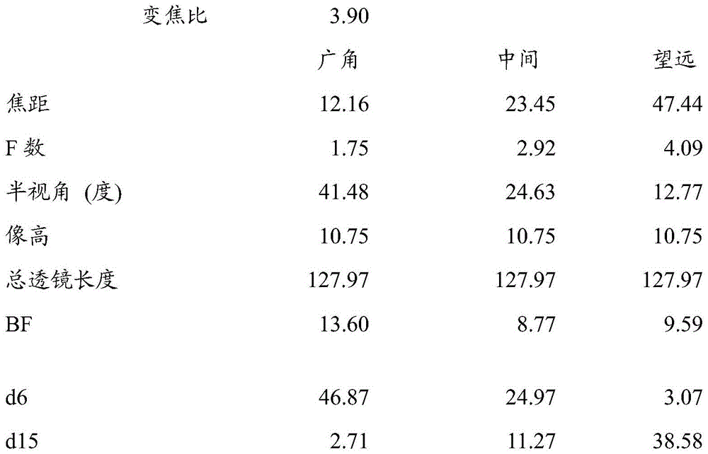

Lens unit data

Unit focal length of each of lens G43 and cemented lenses "a" and "b
Lens G4334.5
First cemented lens-1,607.4
Second cemented lens 88.8
[ numerical example 2]
Unit: mm is
Surface data

Aspheric data
Eighth surface
K=0.00000e+000 A4=-7.26616e-006 A6=8.82597e-009
A8=-3.76146e-011
The ninth surface
K=0.00000e+000 A4=3.29007e-006 A6=1.07738e-008
A8=-4.05256e-011 A10=-9.62820e-014 A12=4.28769e-016
Various data

Lens unit data

Unit focal length of each of lens G43 and cemented lenses "a" and "b
Lens G4339.3
First cemented lens-302.7
Second cemented lens 105.8
[ numerical example 3]
Unit: mm is
Surface data

Aspheric data
Eighth surface
K=3.43890e-001 A4=-9.03806e-006 A6=-2.30086e-009
The ninth surface
K=-2.45855e-001 A4=2.77086e-007 A6=-1.22769e-008
A8=1.35106e-010 A10=-7.26658e-013 A12=1.49286e-015
Various data

Lens unit data

Unit focal length of each of lens G43 and cemented lenses "a" and "b
Lens G4337.89
First cemented lens 2,065.4
Second cemented lens 79.1
[ numerical example 4]
Unit: mm is
Surface data


Aspheric data
Eighth surface
K=0.00000e+000 A4=-1.66569e-005 A6=-1.28563e-008
A8=-5.41482e-010 A10=3.44305e-012 A12=-1.06396e-014
The ninth surface
K=0.00000e+000 A4=-6.10487e-006 A6=-1.14451e-008
A8=-4.37860e-010 A10=2.76154e-012 A12=-8.14534e-015
Various data

Lens unit data


[ numerical example 5]
Unit: mm is
Surface data


Aspheric data
Eighth surface
K=0.00000e+000 A4=-1.37943e-005 A6=1.52797e-008
A8=-3.30276e-010 A10=1.07445e-012 A12=-3.19201e-015
The ninth surface
K=0.00000e+000 A4=-5.46849e-006 A6=8.57550e-009
A8=-1.92760e-010 A10=2.46482e-013 A12=-9.05382e-016
Various data

Lens unit data


[ numerical example 6]
Unit: mm is
Surface data

Aspheric data
Eighth surface
K=0.00000e+000 A4=-7.99083e-006 A6=1.03604e-009
The ninth surface
K=1.77314e+000 A4=5.12885e-006 A6=-1.32177e-009
A8=7.51745e-011 A10=-4.54528e-013 A12=1.11736e-015
Various data

Focal length of each lens unit

Unit focal length of each of lens G43 and cemented lenses "a" and "b
Lens G4335.12
First cemented lens-2,019.3
Second cemented lens 87.2
[ numerical example 7]
Unit: mm is
Surface data

Aspheric data
Eighth surface
K=0.00000e+000 A4=-1.30185e-005 A6=3.96680e-008
A8=-2.25320e-010 A10=6.55663e-013 A12=5.58643e-015
The ninth surface
K=0.00000e+000 A4=2.67549e-006 A6=2.76907e-008
A8=1.16606e-010 A10=-1.77003e-012 A12=1.27104e-014
Various data

Lens unit data

[ numerical example 8]
Unit: mm is
Surface data

Aspheric data
Eighth surface
K=0.00000e+000 A4=-3.51294e-005 A6=-7.19525e-008
A8=-2.78685e-011 A10=-2.80560e-012 A12=1.62205e-014
The ninth surface
K=0.00000e+000 A4=-1.96741e-005 A6=-5.25613e-008
A8=1.31302e-011 A10=-1.85017e-012 A12=1.00084e-014
Various data

Lens unit data

[ numerical example 9]
Unit: mm is
Surface data

Aspheric data
The seventh surface
K=0.00000e+000 A4=-5.72822e-006 A6=-5.53282e-008
A8=6.85585e-010 A10=-2.83359e-012 A12=4.59793e-015
Eighth surface
K=0.00000e+000 A4=1.87082e-005 A6=-4.44276e-008
A8=5.91147e-010 A10=-2.21901e-012 A12=3.46366e-015
Various data

Lens unit data

[ numerical example 10]
Unit: mm is
Surface data


Aspheric data
Eighth surface
K=0.00000e+000 A4=-1.47811e-005 A6=-5.54400e-008
A8=7.77209e-011 A10=-7.02865e-013 A12=-1.67398e-015
The ninth surface
K=0.00000e+000 A4=-3.42729e-006 A6=-5.24578e-008
A8=1.20213e-010 A10=-9.58136e-013 A12=-6.66911e-018
Various data

Lens unit data

TABLE 1

TABLE 2

TABLE 3

While the present invention has been described with reference to exemplary examples, it is to be understood that the invention is not limited to the disclosed exemplary examples. The scope of the following claims is to be accorded the broadest interpretation so as to encompass all such modifications and equivalent structures and functions.
Claims (24)
1. A zoom lens comprising a plurality of lens units, characterized in that
The plurality of lens units include, in order from an object side to an image side: a first lens unit having a negative refractive power, a second lens unit having a positive refractive power, a third lens unit having a negative refractive power, and a fourth lens unit having a positive refractive power,
wherein the second lens unit is configured to move toward the object side for zooming from the wide-angle end to the telephoto end,
wherein the third lens unit is configured to move for zooming,
wherein a spacing between each pair of adjacent lens units is changed for zooming from a wide-angle end to a telephoto end,
wherein, at a telephoto end, compared with a wide-angle end, an interval between the first lens unit and the second lens unit is smaller, an interval between the second lens unit and the third lens unit is larger, an interval between the third lens unit and the fourth lens unit is larger, and the fourth lens unit is positioned closer to the image side,
wherein the third lens unit is composed of a single optical element,
wherein the fourth lens unit includes a plurality of lenses arranged at intervals, and
wherein the following conditional expressions are satisfied:
0.8<|f3/f4|<3.0;
2.5< | f3/L34t | <5.0, and
1.2<|f1/D1|<2.0,
where f3 denotes a focal length of the third lens unit, f4 denotes a focal length of the fourth lens unit, L34t denotes an interval between the third lens unit and the fourth lens unit at the telephoto end, D1 denotes a distance on an optical axis from a lens surface closest to the object side to a lens surface closest to the image side in the first lens unit, and f1 denotes a focal length of the first lens unit.
2. The zoom lens of claim 1, wherein the fourth lens unit comprises at least two positive lenses and at least one negative lens.
3. The zoom lens according to claim 1, wherein the following conditional expression is satisfied:
1.5<f4/L34t<5.0。
4. the zoom lens according to claim 1, wherein the following conditional expression is satisfied:
1.5< f3/f1< 3.0; and
1.0<|f4/f1|<2.0,
where f1 denotes the focal length of the first lens unit.
5. The zoom lens according to claim 1, wherein the following conditional expression is satisfied:
2.0<f4/D4<4.0,
where D4 denotes a distance on the optical axis from the lens surface closest to the object side to the lens surface closest to the image side in the fourth lens unit.
6. An image pickup apparatus characterized by comprising:
the zoom lens of claim 1; and
an image pickup element configured to receive an image formed by the zoom lens.
7. An image pickup system characterized by comprising:
the zoom lens of claim 1; and
a controller configured to control the zoom lens for zooming.
8. A zoom lens comprising a plurality of lens units,
the plurality of lens units are constituted by, in order from the object side to the image side: a first lens unit having a negative refractive power, a second lens unit having a positive refractive power, a third lens unit having a negative refractive power, and a fourth lens unit having a positive refractive power,
wherein the first lens unit is configured not to move for zooming,
wherein the second lens unit, the third lens unit, and the fourth lens unit are configured to move for zooming,
wherein an interval between each pair of adjacent lens units is changed for zooming,
wherein the fourth lens unit includes at least two lenses, and
wherein the following conditional expressions are satisfied:
1.0<f2/fw<3.5;
-20.0< M2/M4< -5.0, and
1.2<|f1/D1|<2.0,
where f2 denotes a focal length of the second lens unit, fw denotes a focal length of the zoom lens at the wide-angle end, M2 denotes a moving amount of the second lens unit for zooming from the wide-angle end to the telephoto end, M4 denotes a moving amount of the fourth lens unit for zooming from the wide-angle end to the telephoto end, D1 denotes a distance on an optical axis from a lens surface closest to the object side to a lens surface closest to the image side in the first lens unit, and f1 denotes a focal length of the first lens unit.
9. The variable focus lens as claimed in claim 8,
wherein the fourth lens unit is composed of, in order from the object side to the image side, a positive lens, a negative lens, and a positive lens, and
wherein the following conditional expressions are satisfied:
0.65<f4p/f4<1.30,
where f4p denotes a focal length of a positive lens disposed closest to the image side of the fourth lens unit, and f4 denotes a focal length of the fourth lens unit.
10. The zoom lens according to claim 8, wherein the following conditional expression is satisfied:
0.45<f2/f4<1.00,
where f4 denotes the focal length of the fourth lens unit.
11. The zoom lens according to claim 8, wherein the following conditional expression is satisfied:
-7.0<f3/D34wt<-3.0,
where D34wt denotes a difference in spacing between the third lens unit and the fourth lens unit at the wide-angle end and the telephoto end, and f3 denotes a focal length of the third lens unit.
12. The variable focus lens as claimed in claim 8,
wherein, of the at least two lenses included in the fourth lens unit, the lens G4b disposed closest to the image side and the lens G4a adjacent to the lens G4b of the fourth lens unit are disposed with a space between the lens G4b and the lens G4a, and
wherein the following conditional expressions are satisfied:
-0.40<(Ra-Rb)/(Ra+Rb)<-0.05,
where Ra denotes a radius of curvature of the lens surface on the image side of the lens G4a, and Rb denotes a radius of curvature of the lens surface on the object side of the lens G4 b.
13. The variable focus lens as claimed in claim 8,
wherein the third lens unit is composed of a negative lens,
wherein the third lens unit is configured to move along a locus convex toward the object side for zooming from the wide-angle end to the telephoto end, and
wherein the following conditional expressions are satisfied:
73<ν3d<100,
wherein v3d denotes the abbe number of the material of the one negative lens of the third lens unit.
14. The variable focus lens as claimed in claim 8,
wherein the second lens unit includes, in order from the object side to the image side: a positive lens having an aspherical surface, a first cemented lens composed of a positive lens and a negative lens made of materials different from each other, and a second cemented lens composed of a positive lens and a negative lens made of materials different from each other, and
wherein the following conditional expressions are satisfied:
0.00≤|f2b/f2a|<0.60,
where f2a denotes a focal length of the first cemented lens, and f2b denotes a focal length of the second cemented lens.
15. An image pickup apparatus characterized by comprising:
the zoom lens of claim 8; and
an image pickup element configured to receive an image formed by the zoom lens,
wherein the following conditional expressions are satisfied:
0.60<(tanωw/tanωt)/(β2t/β2w)<0.90,
where ω w denotes a maximum value of the half angle of view at the wide-angle end, ω t denotes a maximum value of the half angle of view at the telephoto end, β 2w denotes a lateral magnification of the second lens unit at the wide-angle end, and β 2t denotes a lateral magnification of the second lens unit at the telephoto end.
16. A zoom lens comprising a plurality of lens units,
the plurality of lens units include, in order from an object side to an image side: a first lens unit, a second lens unit, a third lens unit, and a fourth lens unit, the first lens unit having a negative refractive power,
wherein the first lens unit is configured not to move for zooming,
wherein the second lens unit, the third lens unit, and the fourth lens unit are configured to move independently along different trajectories from each other for zooming,
wherein an interval between each pair of adjacent lens units is changed for zooming,
wherein the second lens unit, the third lens unit, and the fourth lens unit each include a lens α made of a material satisfying the following conditional expression:
70< vd < 100; and
0.52<θgF<0.56,
wherein vd denotes an Abbe number of the material, and θ gF denotes a partial dispersion ratio of the material, and
wherein the following conditional expressions are satisfied:
1.2<|f1/D1|<2.0,
where D1 denotes a distance on the optical axis from the lens surface closest to the object side to the lens surface closest to the image side in the first lens unit, and f1 denotes a focal length of the first lens unit.
17. The variable focus lens as claimed in claim 16,
wherein a sign of a refractive power of a lens alpha included in the second lens unit is the same as a sign of a refractive power of the second lens unit,
wherein a sign of a refractive power of a lens α included in the third lens unit is the same as that of a refractive power of the third lens unit, and
wherein a sign of a refractive power of the lens α included in the fourth lens unit is the same as a sign of a refractive power of the fourth lens unit.
18. The variable focus lens as claimed in claim 16,
wherein the second lens unit has a positive refractive power,
wherein the third lens unit has a negative refractive power, and
wherein the fourth lens unit has a positive refractive power.
19. The zoom lens of claim 16, wherein the following conditional expression is satisfied:
-5.5<f3/fw<-1.0,
where f3 denotes a focal length of the third lens unit, and fw denotes a focal length of the zoom lens at the wide-angle end.
20. The zoom lens of claim 16, wherein the following conditional expression is satisfied:
2.0<f4/fw<5.0,
where f4 denotes a focal length of the fourth lens unit, and fw denotes a focal length of the zoom lens at the wide-angle end.
21. The variable focus lens as claimed in claim 16,
wherein at least one lens α included in the second lens unit is composed of a positive lens, and
wherein the following conditional expressions are satisfied:
0.4<f2p/f2<2.0,
where f2p denotes a focal length of the positive lens, and f2 denotes a focal length of the second lens unit.
22. The variable focus lens as claimed in claim 16,
wherein at least one lens α included in the third lens unit is composed of a negative lens, and
wherein the following conditional expressions are satisfied:
0.5<f3n/f3<2.0,
wherein f3n denotes a focal length of the negative lens, and f3 denotes a focal length of the third lens unit.
23. The variable focus lens as claimed in claim 16,
wherein at least one lens α included in the fourth lens unit is composed of a positive lens, and
wherein the following conditional expressions are satisfied:
0.4<f4p/f4<2.0,
where f4p denotes a focal length of the positive lens, and f4 denotes a focal length of the fourth lens unit.
24. The zoom lens of claim 16, wherein the following conditional expression is satisfied:
2.0<β2t/β2w<6.0,
where β 2w denotes a lateral magnification of the second lens unit at the wide-angle end, and β 2t denotes a lateral magnification of the second lens unit at the telephoto end.
Applications Claiming Priority (6)
| Application Number | Priority Date | Filing Date | Title |
|---|---|---|---|
| JP2018-001102 | 2018-01-09 | ||
| JP2018-001101 | 2018-01-09 | ||
| JP2018001101A JP7020925B2 (en) | 2018-01-09 | 2018-01-09 | Zoom lens and image pickup device with it, image pickup system |
| JP2018001102A JP7016701B2 (en) | 2018-01-09 | 2018-01-09 | Zoom lens and image pickup device with it, image pickup system |
| JP2018001103A JP7027170B2 (en) | 2018-01-09 | 2018-01-09 | Zoom lens and image pickup device with it, image pickup system |
| JP2018-001103 | 2018-01-22 |
Publications (2)
| Publication Number | Publication Date |
|---|---|
| CN110018552A CN110018552A (en) | 2019-07-16 |
| CN110018552B true CN110018552B (en) | 2022-04-05 |
Family
ID=67139519
Family Applications (1)
| Application Number | Title | Priority Date | Filing Date |
|---|---|---|---|
| CN201910005933.2A Active CN110018552B (en) | 2018-01-09 | 2019-01-04 | Zoom lens, image pickup apparatus, and image pickup system including zoom lens |
Country Status (2)
| Country | Link |
|---|---|
| US (1) | US11061203B2 (en) |
| CN (1) | CN110018552B (en) |
Families Citing this family (10)
| Publication number | Priority date | Publication date | Assignee | Title |
|---|---|---|---|---|
| WO2020044410A1 (en) * | 2018-08-27 | 2020-03-05 | 株式会社ニコン | Scanning optical system and scanning-type confocal microscope |
| US10983336B2 (en) | 2019-02-21 | 2021-04-20 | Canon Kabushiki Kaisha | Dome cover, image pickup apparatus, and image pickup system |
| JP7341800B2 (en) | 2019-09-04 | 2023-09-11 | キヤノン株式会社 | Zoom lenses and imaging devices |
| EP4063931B1 (en) * | 2019-11-18 | 2026-03-25 | LG Innotek Co., Ltd. | Optical system and camera module including same |
| CN110873950A (en) * | 2019-11-29 | 2020-03-10 | 浙江大学 | Endoscope Objective Zoom Optical System |
| JP7483513B2 (en) * | 2020-06-08 | 2024-05-15 | キヤノン株式会社 | Zoom lens and imaging device |
| JP7612439B2 (en) | 2021-02-03 | 2025-01-14 | キヤノン株式会社 | Zoom lens and imaging device |
| JP2023088163A (en) * | 2021-12-14 | 2023-06-26 | キヤノン株式会社 | OPTICAL SYSTEM AND LENS DEVICE HAVING THE SAME, IMAGING DEVICE, IMAGING SYSTEM |
| CN115561878B (en) * | 2022-09-15 | 2026-04-07 | 玉晶光电(厦门)有限公司 | Optical imaging lens |
| JP2024171233A (en) * | 2023-05-29 | 2024-12-11 | 富士フイルム株式会社 | Optical system and optical device |
Citations (7)
| Publication number | Priority date | Publication date | Assignee | Title |
|---|---|---|---|---|
| JP2010160277A (en) * | 2009-01-07 | 2010-07-22 | Panasonic Corp | Zoom lens system, imaging device, and camera |
| JP2010160276A (en) * | 2009-01-07 | 2010-07-22 | Panasonic Corp | Zoom lens system, imaging device, and camera |
| CN102338927A (en) * | 2010-07-14 | 2012-02-01 | 佳能株式会社 | Zoom lens and image pickup apparatus equipped with zoom lens |
| CN103576300A (en) * | 2012-07-27 | 2014-02-12 | 索尼公司 | Variable focal length lens system and image pickup unit |
| CN104423025A (en) * | 2013-09-10 | 2015-03-18 | 三星电子株式会社 | Zoom lens and electronic apparatus |
| CN105190394A (en) * | 2013-03-18 | 2015-12-23 | 柯尼卡美能达株式会社 | Zoom lens and imaging device |
| CN105785559A (en) * | 2015-01-08 | 2016-07-20 | 株式会社腾龙 | Wide-angle zoom lens and image pickup apparatus |
Family Cites Families (25)
| Publication number | Priority date | Publication date | Assignee | Title |
|---|---|---|---|---|
| JP2004151552A (en) | 2002-10-31 | 2004-05-27 | Olympus Corp | Zoom lens for thin electronic image pickup device |
| JP5006113B2 (en) | 2007-06-12 | 2012-08-22 | 富士フイルム株式会社 | Wide angle zoom lens for projection and projection display device |
| JP5151333B2 (en) | 2007-09-11 | 2013-02-27 | 株式会社リコー | Zoom lens, camera device, and portable information terminal device |
| US9195032B2 (en) | 2011-06-24 | 2015-11-24 | Olympus Corporation | Image pickup apparatus equipped with zoom lens with bent optical path |
| WO2014097355A1 (en) * | 2012-12-19 | 2014-06-26 | パナソニック株式会社 | Zoom lens system, interchangeable lens device, and camera system |
| JP6204676B2 (en) | 2013-03-29 | 2017-09-27 | キヤノン株式会社 | Imaging lens and imaging apparatus having the same |
| JP6192338B2 (en) | 2013-04-03 | 2017-09-06 | キヤノン株式会社 | Zoom lens and imaging apparatus having the same |
| JP6268792B2 (en) | 2013-08-02 | 2018-01-31 | 株式会社ニコン | Zoom lens, optical device, and zoom lens manufacturing method |
| JP6129023B2 (en) | 2013-08-22 | 2017-05-17 | キヤノン株式会社 | Zoom lens and imaging apparatus having the same |
| JP6257251B2 (en) | 2013-10-02 | 2018-01-10 | キヤノン株式会社 | Zoom lens and imaging apparatus having the same |
| JP6300577B2 (en) | 2014-03-05 | 2018-03-28 | キヤノン株式会社 | Zoom lens and imaging apparatus having the same |
| JP6153488B2 (en) | 2014-03-18 | 2017-06-28 | キヤノン株式会社 | Zoom lens and imaging apparatus having the same |
| JP5931117B2 (en) | 2014-05-07 | 2016-06-08 | キヤノン株式会社 | Imaging device |
| JP6494245B2 (en) | 2014-10-29 | 2019-04-03 | キヤノン株式会社 | Zoom lens and imaging apparatus having the same |
| JP6452404B2 (en) | 2014-11-25 | 2019-01-16 | キヤノン株式会社 | Zoom lens and imaging apparatus having the same |
| US9952446B2 (en) | 2014-12-24 | 2018-04-24 | Canon Kabushiki Kaisha | Zoom lens and image pickup apparatus including the same |
| JP6602027B2 (en) | 2015-03-13 | 2019-11-06 | キヤノン株式会社 | Zoom lens and imaging apparatus having the same |
| JP2017107112A (en) * | 2015-12-11 | 2017-06-15 | 富士フイルム株式会社 | Projection zoom lens and projection display device |
| JP6541625B2 (en) | 2016-07-05 | 2019-07-10 | キヤノン株式会社 | Wide attachment, photographing lens having the same, and imaging apparatus |
| US10197778B2 (en) | 2016-10-11 | 2019-02-05 | Canon Kabushiki Kaisha | Zoom lens and image pickup apparatus including the same |
| JP2018084668A (en) | 2016-11-24 | 2018-05-31 | キヤノン株式会社 | Zoom lens and image capturing device having the same |
| JP6818531B2 (en) | 2016-12-05 | 2021-01-20 | キヤノン株式会社 | Imaging optical system and an imaging device having it |
| JP6910819B2 (en) | 2017-02-28 | 2021-07-28 | キヤノン株式会社 | Zoom lens and imaging device with it |
| JP2019070706A (en) | 2017-10-06 | 2019-05-09 | キヤノン株式会社 | Imaging apparatus |
| JP7039241B6 (en) | 2017-10-12 | 2022-04-18 | キヤノン株式会社 | Zoom lens and image pickup device |
-
2019
- 2019-01-02 US US16/237,848 patent/US11061203B2/en active Active
- 2019-01-04 CN CN201910005933.2A patent/CN110018552B/en active Active
Patent Citations (7)
| Publication number | Priority date | Publication date | Assignee | Title |
|---|---|---|---|---|
| JP2010160277A (en) * | 2009-01-07 | 2010-07-22 | Panasonic Corp | Zoom lens system, imaging device, and camera |
| JP2010160276A (en) * | 2009-01-07 | 2010-07-22 | Panasonic Corp | Zoom lens system, imaging device, and camera |
| CN102338927A (en) * | 2010-07-14 | 2012-02-01 | 佳能株式会社 | Zoom lens and image pickup apparatus equipped with zoom lens |
| CN103576300A (en) * | 2012-07-27 | 2014-02-12 | 索尼公司 | Variable focal length lens system and image pickup unit |
| CN105190394A (en) * | 2013-03-18 | 2015-12-23 | 柯尼卡美能达株式会社 | Zoom lens and imaging device |
| CN104423025A (en) * | 2013-09-10 | 2015-03-18 | 三星电子株式会社 | Zoom lens and electronic apparatus |
| CN105785559A (en) * | 2015-01-08 | 2016-07-20 | 株式会社腾龙 | Wide-angle zoom lens and image pickup apparatus |
Also Published As
| Publication number | Publication date |
|---|---|
| CN110018552A (en) | 2019-07-16 |
| US20190212525A1 (en) | 2019-07-11 |
| US11061203B2 (en) | 2021-07-13 |
Similar Documents
| Publication | Publication Date | Title |
|---|---|---|
| CN110018552B (en) | Zoom lens, image pickup apparatus, and image pickup system including zoom lens | |
| US9329372B2 (en) | Zoom lens and image pickup apparatus having the same | |
| JP6192338B2 (en) | Zoom lens and imaging apparatus having the same | |
| JP4881035B2 (en) | Zoom lens and imaging apparatus having the same | |
| EP2921896B1 (en) | Zoom lens and image pickup apparatus having the same | |
| US10126523B2 (en) | Zoom lens and image pickup apparatus having the same | |
| US9069156B2 (en) | Zoom lens and image pickup apparatus having the same | |
| US9405105B2 (en) | Zoom lens system and image pickup apparatus including the same | |
| US20200348495A1 (en) | Zoom lens and image pickup apparatus having the same | |
| EP2407810A2 (en) | Zoom lens and image pickup apparatus | |
| US8873169B2 (en) | Zoom lens and image pickup apparatus using the same | |
| JP2014202841A5 (en) | ||
| JP5253043B2 (en) | Zoom lens and imaging apparatus having the same | |
| CN108732733A (en) | Zoom lens includes the photographic device and camera system of zoom lens | |
| JP7027170B2 (en) | Zoom lens and image pickup device with it, image pickup system | |
| JP7204442B2 (en) | ZOOM LENS AND IMAGING DEVICE HAVING THE SAME | |
| CN111190271B (en) | Zoom lens and imaging device | |
| JP2010122536A (en) | Zoom lens | |
| US8599494B2 (en) | Zoom lens and image pickup apparatus having the same | |
| US12504608B2 (en) | Zoom lens, image pickup apparatus having the same, and imaging system | |
| CN113448068B (en) | Zoom lens and imaging apparatus | |
| JP5197262B2 (en) | Zoom lens and imaging apparatus having the same | |
| CN113031236B (en) | Zoom lens and image pickup apparatus | |
| CN118091907A (en) | Zoom lens and image pickup device having the same | |
| JP5574796B2 (en) | Zoom lens and imaging apparatus having the same |
Legal Events
| Date | Code | Title | Description |
|---|---|---|---|
| PB01 | Publication | ||
| PB01 | Publication | ||
| SE01 | Entry into force of request for substantive examination | ||
| SE01 | Entry into force of request for substantive examination | ||
| GR01 | Patent grant | ||
| GR01 | Patent grant |