CN109952068B - Devices and methods for preventing and treating vasospasm - Google Patents
Devices and methods for preventing and treating vasospasm Download PDFInfo
- Publication number
- CN109952068B CN109952068B CN201780068679.XA CN201780068679A CN109952068B CN 109952068 B CN109952068 B CN 109952068B CN 201780068679 A CN201780068679 A CN 201780068679A CN 109952068 B CN109952068 B CN 109952068B
- Authority
- CN
- China
- Prior art keywords
- stent structure
- struts
- vessel
- electrodes
- electrical conductors
- Prior art date
- Legal status (The legal status is an assumption and is not a legal conclusion. Google has not performed a legal analysis and makes no representation as to the accuracy of the status listed.)
- Active
Links
Images


Classifications
-
- A—HUMAN NECESSITIES
- A61—MEDICAL OR VETERINARY SCIENCE; HYGIENE
- A61B—DIAGNOSIS; SURGERY; IDENTIFICATION
- A61B18/00—Surgical instruments, devices or methods for transferring non-mechanical forms of energy to or from the body
- A61B18/04—Surgical instruments, devices or methods for transferring non-mechanical forms of energy to or from the body by heating
- A61B18/12—Surgical instruments, devices or methods for transferring non-mechanical forms of energy to or from the body by heating by passing a current through the tissue to be heated, e.g. high-frequency current
- A61B18/14—Probes or electrodes therefor
- A61B18/1492—Probes or electrodes therefor having a flexible, catheter-like structure, e.g. for heart ablation
-
- A—HUMAN NECESSITIES
- A61—MEDICAL OR VETERINARY SCIENCE; HYGIENE
- A61N—ELECTROTHERAPY; MAGNETOTHERAPY; RADIATION THERAPY; ULTRASOUND THERAPY
- A61N1/00—Electrotherapy; Circuits therefor
- A61N1/02—Details
- A61N1/04—Electrodes
- A61N1/05—Electrodes for implantation or insertion into the body, e.g. heart electrode
- A61N1/0526—Head electrodes
- A61N1/0529—Electrodes for brain stimulation
-
- A—HUMAN NECESSITIES
- A61—MEDICAL OR VETERINARY SCIENCE; HYGIENE
- A61N—ELECTROTHERAPY; MAGNETOTHERAPY; RADIATION THERAPY; ULTRASOUND THERAPY
- A61N7/00—Ultrasound therapy
- A61N7/02—Localised ultrasound hyperthermia
-
- A—HUMAN NECESSITIES
- A61—MEDICAL OR VETERINARY SCIENCE; HYGIENE
- A61N—ELECTROTHERAPY; MAGNETOTHERAPY; RADIATION THERAPY; ULTRASOUND THERAPY
- A61N7/00—Ultrasound therapy
- A61N7/02—Localised ultrasound hyperthermia
- A61N7/022—Localised ultrasound hyperthermia intracavitary
-
- A—HUMAN NECESSITIES
- A61—MEDICAL OR VETERINARY SCIENCE; HYGIENE
- A61B—DIAGNOSIS; SURGERY; IDENTIFICATION
- A61B18/00—Surgical instruments, devices or methods for transferring non-mechanical forms of energy to or from the body
- A61B2018/00053—Mechanical features of the instrument of device
- A61B2018/0016—Energy applicators arranged in a two- or three dimensional array
-
- A—HUMAN NECESSITIES
- A61—MEDICAL OR VETERINARY SCIENCE; HYGIENE
- A61B—DIAGNOSIS; SURGERY; IDENTIFICATION
- A61B18/00—Surgical instruments, devices or methods for transferring non-mechanical forms of energy to or from the body
- A61B2018/00053—Mechanical features of the instrument of device
- A61B2018/00214—Expandable means emitting energy, e.g. by elements carried thereon
- A61B2018/00267—Expandable means emitting energy, e.g. by elements carried thereon having a basket shaped structure
-
- A—HUMAN NECESSITIES
- A61—MEDICAL OR VETERINARY SCIENCE; HYGIENE
- A61B—DIAGNOSIS; SURGERY; IDENTIFICATION
- A61B18/00—Surgical instruments, devices or methods for transferring non-mechanical forms of energy to or from the body
- A61B2018/00315—Surgical instruments, devices or methods for transferring non-mechanical forms of energy to or from the body for treatment of particular body parts
- A61B2018/00321—Head or parts thereof
-
- A—HUMAN NECESSITIES
- A61—MEDICAL OR VETERINARY SCIENCE; HYGIENE
- A61B—DIAGNOSIS; SURGERY; IDENTIFICATION
- A61B18/00—Surgical instruments, devices or methods for transferring non-mechanical forms of energy to or from the body
- A61B2018/00315—Surgical instruments, devices or methods for transferring non-mechanical forms of energy to or from the body for treatment of particular body parts
- A61B2018/00345—Vascular system
- A61B2018/00404—Blood vessels other than those in or around the heart
- A61B2018/00416—Treatment of aneurisms
-
- A—HUMAN NECESSITIES
- A61—MEDICAL OR VETERINARY SCIENCE; HYGIENE
- A61B—DIAGNOSIS; SURGERY; IDENTIFICATION
- A61B18/00—Surgical instruments, devices or methods for transferring non-mechanical forms of energy to or from the body
- A61B2018/00315—Surgical instruments, devices or methods for transferring non-mechanical forms of energy to or from the body for treatment of particular body parts
- A61B2018/00434—Neural system
- A61B2018/00446—Brain
-
- A—HUMAN NECESSITIES
- A61—MEDICAL OR VETERINARY SCIENCE; HYGIENE
- A61B—DIAGNOSIS; SURGERY; IDENTIFICATION
- A61B18/00—Surgical instruments, devices or methods for transferring non-mechanical forms of energy to or from the body
- A61B2018/00636—Sensing and controlling the application of energy
- A61B2018/00773—Sensed parameters
- A61B2018/00875—Resistance or impedance
-
- A—HUMAN NECESSITIES
- A61—MEDICAL OR VETERINARY SCIENCE; HYGIENE
- A61B—DIAGNOSIS; SURGERY; IDENTIFICATION
- A61B18/00—Surgical instruments, devices or methods for transferring non-mechanical forms of energy to or from the body
- A61B18/04—Surgical instruments, devices or methods for transferring non-mechanical forms of energy to or from the body by heating
- A61B18/12—Surgical instruments, devices or methods for transferring non-mechanical forms of energy to or from the body by heating by passing a current through the tissue to be heated, e.g. high-frequency current
- A61B18/14—Probes or electrodes therefor
- A61B2018/1405—Electrodes having a specific shape
- A61B2018/1435—Spiral
- A61B2018/1437—Spiral whereby the windings of the spiral touch each other such as to create a continuous surface
-
- A—HUMAN NECESSITIES
- A61—MEDICAL OR VETERINARY SCIENCE; HYGIENE
- A61N—ELECTROTHERAPY; MAGNETOTHERAPY; RADIATION THERAPY; ULTRASOUND THERAPY
- A61N7/00—Ultrasound therapy
- A61N2007/0004—Applications of ultrasound therapy
- A61N2007/0021—Neural system treatment
-
- A—HUMAN NECESSITIES
- A61—MEDICAL OR VETERINARY SCIENCE; HYGIENE
- A61N—ELECTROTHERAPY; MAGNETOTHERAPY; RADIATION THERAPY; ULTRASOUND THERAPY
- A61N7/00—Ultrasound therapy
- A61N2007/0004—Applications of ultrasound therapy
- A61N2007/0021—Neural system treatment
- A61N2007/003—Destruction of nerve tissue
Landscapes
- Health & Medical Sciences (AREA)
- Engineering & Computer Science (AREA)
- Life Sciences & Earth Sciences (AREA)
- General Health & Medical Sciences (AREA)
- Animal Behavior & Ethology (AREA)
- Veterinary Medicine (AREA)
- Public Health (AREA)
- Biomedical Technology (AREA)
- Nuclear Medicine, Radiotherapy & Molecular Imaging (AREA)
- Radiology & Medical Imaging (AREA)
- Surgery (AREA)
- Heart & Thoracic Surgery (AREA)
- Cardiology (AREA)
- Medical Informatics (AREA)
- Physics & Mathematics (AREA)
- Plasma & Fusion (AREA)
- Otolaryngology (AREA)
- Molecular Biology (AREA)
- Psychology (AREA)
- Neurology (AREA)
- Neurosurgery (AREA)
- Media Introduction/Drainage Providing Device (AREA)
- Surgical Instruments (AREA)
- Electrotherapy Devices (AREA)
- Prostheses (AREA)
Abstract
The invention relates to a device having a support structure (2) for insertion into an intracranial vessel (6) of a human or animal body, wherein the stent structure (2) has an expanded state in which it is able to contact the inner wall of the vessel (6) and a compressed state, in the compressed state, the stent structure (2) is movable within the microcatheter (4) through the blood vessel (6), wherein the stent structure (2) is connected to an insertion aid (3), wherein the stent structure (2) is independently transformable to an expanded state upon release from the microcatheter (4), wherein the stent structure (2) has an electrical conductor (13) by means of which electrical, radio-frequency or ultrasound pulses can be applied to nerve fibres extending in the wall of the vessel (6) in order to temporarily or permanently reduce the function of the nerve fibres and prevent or treat vasospasm.
Description
Technical Field
The present invention relates to a device or arrangement having a stent structure for insertion into an intracranial blood vessel of a human or animal body, wherein the stent structure has an expanded state in which the stent structure is capable of being in contact with an inner wall of the blood vessel and a compressed state in which the stent structure located in a microcatheter is movable through the blood vessel, wherein the stent structure is connected to an insertion aid and wherein the stent structure is capable of automatically transforming into the expanded state upon release from the microcatheter. The device is used for preventing or treating vasospasm. The invention also relates to a corresponding method.
Background
Spastic vasoconstriction is called vasospasm. Vasospasm involves the risk that a sufficient amount of blood is no longer supplied to the downstream blood vessels (ischemia), which may lead to tissue necrosis, thereby cutting off perfusion. Especially in the brain region, vasospasm can occur several days after subarachnoid hemorrhage (SAH), often as a result of rupture of the aneurysm. Other causes of subarachnoid hemorrhage are cerebral injury and hemorrhage due to vascular malformation or tumor. Blood entering the subarachnoid space washes around the blood vessels located there and is considered to be the most important trigger for vasospasm. Approximately 60% of SAH patients develop more or less abrupt vasospasm between approximately days 5 and 20 after bleeding. If arterial blood vessels are severely restricted, dependent brain tissue becomes starved and may suffer irreversible damage (cerebral infarction). Of all patients who survive SAH, approximately 15% to 20% of patients experience permanent neurological damage with resulting disability. Approximately 5% of SAH patients who initially survive subsequently die due to cerebral vasospasm. In this regard, vasospasm is one of the leading causes of stroke in this area, or even death after rupture of the aneurysm and/or bleeding therefrom, or due to surgery.
In general, treatment of vasospasm with drugs, in particular calcium channel blockers or drugs used, results in increased levels of NO in the blood. One example of a calcium channel blocker is nimodipine, which is often used after subarachnoid hemorrhage to prevent vasospasm. However, such drug-based treatments are associated with significant side effects and are both costly and time consuming.
Other possibilities for treating vasospasm are intensive medical measures such as increasing arterial blood pressure and increasing circulating blood volume, widening narrowed blood vessels with the help of balloons, blocking the stellate ganglia, and surgical elimination of sympathetic fibers (sympathetical elimination). These treatments vary in effectiveness, are sometimes very complex, and are often ineffective for a sufficiently long time. Of course, since sympathetic nerve fibers in the wall of cerebral arteries are essentially involved in the formation of cerebral vasospasm, blockade of the stellate ganglia and surgical sympathetically elimination are considered to be effective. However, these methods are far from adequate for the complete prevention and treatment of cerebral vasospasm, since the blocking of the stellate ganglia lasts only a few hours and the surgical sympathectomy is limited to a narrowly defined section of the blood vessel, which must be prepared surgically for this purpose.
Disclosure of Invention
It is therefore an object of the present invention to provide a method that allows preventing and treating vasospasm in some other way.
This object is achieved, as proposed by the present invention, by a device/apparatus having a stent structure for insertion into an intracranial vessel of a human or animal body, wherein the stent structure has an expanded state in which the stent structure is able to abut an inner wall of the vessel and a compressed state in which the stent structure is movable through the vessel when the stent structure is inside a microcatheter, wherein the stent structure is connected to an insertion aid, and wherein the stent structure is able to automatically transition to the expanded state upon release from the microcatheter, wherein the stent structure has an electrical conductor by means of which an electrical, high frequency or ultrasound pulse can be applied to nerve fibres extending in the vessel wall of the vessel to temporarily or permanently reduce the function of the nerve fibres to allow prevention or treatment of vasospasm.
The invention is therefore based on the use of a stent structure for the intravascular denervation of arteries supplying the brain. Endovascular procedures for denervation of sympathetic nerve fibers are known in the art of renal artery denervation, but are used to disrupt nerve fibers between the brain and the kidney to reduce the release of substances that increase blood pressure. Moreover, balloon catheters used for this purpose are not suitable for use in the intracranial region.
Physically, the pulses may be applied to the nerve fibers in the form of High Frequency (HF) signals, direct current, alternating current, or ultrasound. Usually, denervation is ultimately based on heating of the vessel wall, which results in the elimination or impairment of nerve fiber function. The use of high frequency or ultrasound pulses is preferred as this allows energy maxima to be generated in the depth of the surrounding vessel wall, so in particular nerve fibres are damaged rather than the entire vessel wall. The nerve fibers referred to herein are those of the sympathetic nervous system.
A single pulse application to the nerve fibres typically lasts for a period of 30 to 120 seconds, whereby the nerve fibres can be heated to a temperature between 50 ℃ and 80 ℃. The penetration depth of the energy into the vessel wall is for example between 1mm and 3 mm. In the case of HF pulses, the frequency is typically 300kHz to 4000 kHz. High frequency in the sense of the present invention means electromagnetic waves with a frequency >1kHz, including microwaves with a frequency higher than 1 GHz.
Stents, also known as endovascular prostheses, are commonly used to treat vascular contractions and are permanently implanted at the site of the contraction to hold the vessel lumen open. Typically, stents have a tubular structure and are produced by laser cutting to obtain surfaces consisting of struts, with openings between struts, or they consist of a wire braid. The stent may be moved to a placement site through a catheter where the stent is expanded; in the case of self-expanding stents made of shape memory materials, expansion and contact with the inner wall of the vessel occurs automatically. After final placement, only the stent remains at the target site; removing the catheter, guide wire or push wire and other auxiliary devices from the vascular system. Similarly designed implants with a higher surface density, so-called shunts, are also used for occlusion of aneurysms, since they are placed in front of the neck of the aneurysm. However, the prevention or treatment of vasospasm with the aid of a scaffold structure has not been described.
The device of the invention is used for the intravascular denervation of arteries supplying the brain with blood, for the prevention and treatment of vasospasm caused by bleeding. The device is particularly flexible and can therefore be inserted into an artery inside the skull. The device only alters arterial blood flow to such a small extent that there is no risk of cerebral insufficiency. The device may be used only once, left in the vessel to be treated for several days or permanently implanted.
The effect of the proposed device is based on the reduction or interruption of the function of nerve fibres in the vessel wall of the affected vessel. This can range from temporary reduction of function to permanent destruction/elimination of nerve fibers. To reduce/interrupt the function of the nerve fibers, energy is delivered from the device to the vessel wall, where the energy transmission is by electrical, high frequency or ultrasound pulses. These lead to atrophy/sclerosis of at least part of the nerve fibres. Energy is delivered to the vessel wall by means of an electrode or an ultrasound transmitter, wherein the energy supply to the electrode/ultrasound transmitter is effected by means of an electrical conductor which is part of the stent structure. The electrodes that typically constitute the ends of the electrical conductors are typically enlarged compared to the conductors themselves. For example, the electrical conductor may be provided with a circular or square enlarged end section which acts as an electrode.
The stent structure is self-expanding, i.e. after release from the microcatheter (in which it is advanced to the target site), it assumes its expanded state independently of external influences, attaching itself to the inner wall of the affected vessel. Furthermore, the transition from the compressed state to the expanded state should be reversible, i.e. the stent structure should be able to transition from the expanded state back to the compressed state, in particular so that it can be withdrawn into the micro-catheter after use and in this way be removed from the vascular system. Self-expanding stent structures of this type are basically well known in the prior art, for example in order to keep a blood vessel permanently open in the event of vasoconstriction caused by arteriosclerosis. The self-expanding stent structure is advantageous in that it can be particularly delicate since additional devices such as a balloon required for expansion can be omitted. Typically, self-expanding stent structures are made of materials having shape memory properties, particularly shape memory metals such as nickel-titanium alloys. In this case, nitinol is used very frequently. However, polymers or other alloys having shape memory properties are also contemplated.
The insertion aid is typically a push wire, also referred to as a guide wire. Such push wires are also used in a similar manner for placing implants intended to remain permanently in the vascular system, however, in this case the push wires are connected to the implant by a cut-off point and said cut-off point can be designed for mechanical, thermal, electrolytic or chemical detachment. On the other hand, the device according to the invention is usually only temporarily navigated to the target location in order to apply energy to the vessel wall. The insertion aid is preferably made of stainless steel, nitinol or cobalt-chromium alloy. However, it is also conceivable to have a stent structure designed for permanent placement in the vascular system, i.e. the structure has a separation point between the insertion aid and the stent structure. Typically, the stent structure is connected at its proximal end to an insertion aid, but other connections between the insertion aid and the stent structure are not excluded.
The insertion aid or push wire is preferably attached radially outward to the proximal end of the stent structure. In other words, the connection between the insertion aid and the stent structure is not in the center of the stent structure, but is arranged eccentrically at or near the inner wall of the vessel. In this way, the blood flow is only impeded to a small extent. Furthermore, the eccentric arrangement of the insertion aid facilitates retraction of the device into the microcatheter.
Typically, the treatment is performed in such a way that the device of the invention, disposed within the microcatheter, is moved towards the site of placement, i.e. the site where vasospasm occurs or is likely to occur. After this, the microcatheter is retracted in the proximal direction, resulting in deployment of the stent structure, which now expands and contacts the inner wall of the vessel. The pulses are then applied to the nerve fibers in the vessel wall, which may be repeated, even over a longer period of hours or days. Finally, the microcatheter is again moved in the distal direction to encompass the stent structure, and then the microcatheter is retracted with the device. The treatment described herein may be repeated for several consecutive days.
The terms "proximal" and "distal" should be understood as meaning that the portion that points toward the attending physician when inserting the device is referred to as proximal, and the portion that points away from the attending physician is referred to as distal. Typically, the device is moved forward in the distal direction by means of a microcatheter. The term "axial" refers to the longitudinal axis of the device extending from proximal to distal, while the term "radial" refers to a horizontal/planar surface extending perpendicular to the axial direction.
The treatment with the proposed device can be accompanied by a drug-based treatment, for example with nimodipine. This may be applied intra-arterially to the site where it is envisaged to treat or prevent vasospasm.
Basically, the stent structure may be made up of individual interconnected struts. Such a stent structure may be manufactured in a known manner by laser cutting techniques. Furthermore, it is believed to be advantageous to treat the stent structure by electropolishing to make it smoother and more rounded, thereby making it less traumatic. This also reduces the risk that bacteria or other impurities may adhere to the structure.
Alternatively, the scaffold structure may also be a mesh structure, which is composed of individual threads in the form of a braid. In this case, the wires extend generally helically along the longitudinal axis, with intersecting opposing wires extending above and below each other at the intersection points, resulting in honeycomb openings being formed between the wires. The total number of lines is preferably between 8 and 64. As the wire forming the mesh structure, a separate wire made of metal may be used, but also a stranded wire, i.e. several small diameter wires arranged to form a filament, may be provided, preferably twisted around each other.
An advantage of a stent structure comprising interconnected struts over a mesh structure of wires is that the struts making up the stent structure will be less prone to longitudinal contraction than the mesh structure during the expansion process, the struts being produced in particular by laser cutting techniques. Longitudinal contraction should be kept to a minimum because the stent structure exerts additional stress on the surrounding vessel wall during longitudinal contraction. Since vasospasm is caused in particular by a stimulus acting on the blood vessel, any additional stress must be avoided when treating vasospasm.
The struts or wires may have a circular, oval, square or rectangular cross-section, in which case the edges are advantageously rounded. When using struts or wires of substantially rectangular cross-section, where the edges are rounded off, also considered to be substantially rectangular, it has proved advantageous to provide struts/wires of a height and width of between 20 μm and 300 μm, preferably between 20 μm and 70 μm. In the case of a circular cross-section, the diameter should be in the range of 20 μm to 300 μm. Whether using struts or braided wires, it is important that the electrical conductors be arranged so as to be able to apply impulses to the nerve fibres. The electrical conductor may be the strut/wire itself, the conductor may be connected to the strut/wire, or the conductor may be a separate component of the stent structure.
According to a preferred embodiment, the stent structure is provided with a ridge extending from a proximal side to a distal side, the struts starting from the ridge and forming a circumference of the stent structure in the expanded state. For example, the scaffolding structure may resemble a human spine with struts from the spine comparable to ribs. In particular, struts starting from a ridge may substantially form a loop when they are in an expanded state, such that they contact the substantially circular inner wall of the blood vessel over all or a majority of the circumference when viewed in cross-section. Notably, the two struts may each form a split ring with a gap. The points of connection between the struts and the spine may also be offset from one another; this reduces the risk that the electrical conductors of the struts will come into contact with each other and create a short circuit.
The struts which originate from the spine and form the split ring may also be composed of two or more partial struts, i.e. two or more partial struts which originate from the spine are parallel to each other and terminate at a common end point. Between the end points formed by the oppositely arranged partial sets of struts, gaps are thus formed. In the case of a strut composed of two partial struts, this embodiment can also be described in such a way that: the two partial struts together form an arc on the spine, the apex of the arc corresponding to the above-mentioned end point.
Regardless of the embodiment in which the struts originate from a common ridge, the struts may also be composed of parallel-running partial struts. A stent structure comprising several narrower partial struts may be radially expanded more reliably than a stent structure having wider struts when the stent structure is not constrained by the exterior of the microcatheter.
The angle formed by the struts from the spine relative to the spine may be a right angle, but deviations from a right angle may also be provided, for example a certain degree of extension in the proximal or distal direction. Thus, the angle formed at the connection point between the strut and the ridge may in the expanded state be in the range between 30 ° and 90 °, the strut pointing in the distal and proximal direction. However, more typical are embodiments where the struts point in a distal direction. The struts may be provided with electrical conductors to allow transmission of the impulses to the nerve fibres. It is sufficient if only the individual struts starting from the ridge have electrical conductors; however, it is also possible to provide all struts with electrical conductors. Further, the number of struts starting from a ridge may be selectively chosen, but the minimum number of struts is one.
The electrical conductors should converge at the proximal end of the stent structure and be connected to the insertion aid. Over the length of the insertion aid there is typically an electrical connection between the electrical conductor and a current source, typically located outside the body. This ensures that electrical or other pulses can be transmitted through the scaffold under external control. However, a power supply as part of the device itself can also be envisaged in principle, but in this case such a power supply must be particularly compact to be able to be inserted into intracranial blood vessels. The number of electrical conductors may vary depending on whether a single electrode/ultrasound transmitter pair is employed or whether multiple electrode or ultrasound transmitters pairs are employed. On the one hand, it can be seen that providing a plurality of electrical conductors is advantageous because it allows pulses to be applied simultaneously at different locations on the inner wall of the blood vessel. On the other hand, however, care must be taken to ensure that the entire device/apparatus remains sufficiently flexible to be able to navigate through narrow lumen intracranial vessels.
The individual electrical conductors should be electrically insulated from each other to avoid short circuits. This is especially true if the struts or struts forming the stent structure are arranged relatively close to each other. It may be sufficient that the electrical conductors are electrically isolated only in those regions where they are closely spaced from each other, for example at the proximal end of the stent structure, where the electrical conductors transition to the insertion aid, but it is in principle advantageous that the electrical conductors are completely isolated except suitably in the region of the electrical conductors through which the pulses are applied, i.e. typically at the end where the electrodes are arranged.
Embodiments may also be used in which the electrical conductors are electrically insulated, but where electrical insulation is intentionally not provided in some places, in order to be able to transmit pulses at or between these points. Such embodiments are particularly suitable for stent structures comprising a network of individual wires forming a braid. In this case, the expansion of the stent structure quasi-automatically ensures that at least some wires, which can simultaneously perform the function of the electrical conductor, are in contact with the inner wall of the vessel, which also applies to the regions/locations of the electrical conductor where the insulation has been dispensed with. One advantage of this stent structure is that it can be used for different vessels having different diameters.
Furthermore, a device is preferred, wherein pairs of electrical or High Frequency (HF) electrodes are arranged on the circumference of the stent structure in such a way that the electrodes in the expanded state and implanted in the vessel are separated by a gap, so that an applied current flowing through the gap to the electrodes acts on the inner wall of the vessel. The pulses may be electrical pulses or high frequency pulses. In particular, this embodiment may be combined with the above described embodiments, wherein the stent structure is provided with a proximally to distally extending ridge from which the struts provided with the electrical conductors originate. In this way, pairs of struts may start from the ridge, with electrodes arranged at the ends of the associated strut pair. In view of the small dimensions of the entire stent structure, the spacing between the electrodes is of course also small and usually corresponds to ≦ 1 mm.
It is also considered useful if the electrodes are provided with radiopaque markers. In this way, the attending physician can see if the electrodes are still a short distance apart, or if they are touching each other, i.e., causing a short circuit to occur, as desired. Since the struts, even in the expanded state, are subjected to radial forces exerted by the inner wall of the vessel, the degree to which the stent structure is compressed depends on the inner diameter of the vessel. For example, a certain stent structure may be used with a sufficiently large vessel because there is a sufficiently large gap between the electrodes, whereas for smaller sized vessels there may be contact between the electrodes due to greater compression of the stent structure, resulting in the transmission of pulses being prevented. Thus, different stent structures may be used for vessels having different inner diameters.
Another conceivable embodiment provides a bridge made of insulating material, which is arranged between the electrodes. In this way, short circuits can be effectively prevented. If the insulating material additionally has some flexibility, the stent structure will be able to adapt to the inner diameter of the vessel, so that a given stent structure can be used for vessels of different sizes.
It is considered to be particularly advantageous if the electrode has a radiopaque core inside which can be used as a marker. One or more radiopaque markers may also be disposed elsewhere on the device to allow the attending physician to visualize placement and deployment of the device. For example, radiopaque markers may be composed of platinum, palladium, platinum-iridium, tantalum, gold, tungsten, or other metals that are opaque to radiation. Suitable radiopaque markers are particularly useful at sections of the stent structure, particularly at the distal end. The struts or wires of the stent structure may also be provided with a coating comprised of a radiopaque material, such as a gold coating. The coating may for example have a thickness of 1 μm to 6 μm. Such gold coatings may be used in addition to or in place of radiopaque markers.
It is considered advantageous to provide the scaffold structure with several pairs of electrodes that can generate electrical or high frequency pulses. In this way, pulses can be applied at several locations of the vessel wall, either simultaneously or consecutively. This is important because the vessel wall usually contains several nerve fibers, the success of their denervation pairing treatment is important.
The electrodes, electrode pairs and/or ultrasound transmitters (generally: pulse generators) may be arranged circumferentially offset from each other when viewed in the longitudinal direction of the stent structure. In other words, electrodes arranged from proximal to distal in different sections of the stent structure also act on different sections relative to the inner circumference of the vessel. In the cross-sectional view, the pulse generator may be located, for example, at the 12 o 'clock position, the pulse generator at the 3 o' clock position, the pulse generator at the 6 o 'clock position, and another pulse generator at the 9 o' clock position. Such an embodiment provides the advantage that different nerve fibres extending in a longitudinal direction in a vessel wall can be treated without having to rotate the stent structure. If desired, the stent structure may be advanced distally or retracted proximally to bring specific pairs of electrodes to different circumferential locations of the vessel wall and allow the pulses to act there. This is important because it is relatively easy to advance or retract the device and thus the stent structure, but rotation of the stent structure is difficult to achieve because the device typically already enters the intracranial region over a considerable distance, which makes the exertion of torsional forces much more difficult.
An embodiment is advantageous in which the stent structure comprises a plurality of substantially annular elements, which are spaced apart in the longitudinal direction of the device, each element comprising two electrical conductors belonging to the electrical circuit, which two electrical conductors each terminate in an electrode when the device is implanted in the blood vessel in the expanded state, and which two electrodes are separated from each other by a gap. In particular, said embodiment may be combined with the previously described embodiments, wherein the struts originate from a ridge extending from the proximal to the distal direction, wherein in this example the struts originating from the ridge extend in a first direction with a first electrical conductor and a second strut originating from the ridge extends in a second direction together with a second electrical conductor. Thus, the scaffold structure resembles a human spine with ribs, the ends of which are separated by gaps. Thus, the structure is not closed, but open ring-shaped. As described above, the gaps between the individual struts may be arranged offset from one another for different strut pairs. The gap may also be filled with an electrically insulating material.
Suitably, the device (preferably the support structure) is provided with means for measuring resistance, in particular for measuring impedance (i.e. measurement of alternating current resistance). This resistance measurement is important because different tissues may have different resistances. In order to be able to determine the amount of energy used for denervation of certain nerve fibres, resistance measurements are therefore considered useful. Based on the resistance values thus detected, a data matrix can be constructed, for example, to determine which defined current-voltage signal can be suitably used to achieve a desired effect, for example, to induce a particular temperature. After treatment, the success of the treatment can be checked by performing another resistance measurement.
The resistance measurement does not necessarily have to be integrated into the device proposed by the invention, i.e. a separate device for the resistance measurement is also conceivable.
The stent structure may be permeable, i.e. have openings in the radial direction, but it is also possible to provide the stent structure with a membrane on the inner side, i.e. the luminal side. Outside the lumen, however, the surface of the device is in direct contact with the inner wall of the vessel. In this case, the membrane serves to separate the vessel lumen from the usual metal wires or struts of the stent structure. The membrane may also produce some electrical insulation of the electrical conductors in the direction of the cavity. On the other hand, when the scaffold is present in a compressed state, providing additional membranes requires additional space, making such a scaffold less compact to collapse.
Typically, the stent structure has an open design at the proximal end. At its distal end, the stent structure may also be open, but may also be of closed design. Stents which are open at both ends offer the advantage of blocking as little as possible the blood flow, so that an insufficient blood supply to the downstream vessels and tissues which they supply is prevented. On the other hand, providing a closed structure for the distal end is more atraumatic. It should be noted that the reference to an open structure means that no struts or wires are arranged at the respective ends of the scaffold structure and that the struts/wires are only arranged on the outer circumference of the scaffold structure. However, in the case of a closed end, a stent or wire is also present in the center of the stent structure. However, since there are still openings between the struts or wires, even a closed distal end is not completely impermeable and still allows blood to flow through the respective openings.
An anti-thrombogenic coating of the stent structure is considered advantageous. Such a coating may be applied to the entire stent structure or only to the interior thereof, since the structure remains within the blood vessel for a certain time span, during which a preventive clot possibly formed in a blood vessel that has contracted due to a vasospasm that has occurred is mandatory. The outside of the stent structure may advantageously be coated with an agent that contributes to vessel relaxation, for example with a calcium channel blocker such as nimodipine.
Typically, the diameter of the scaffold in its free expanded state is in the range of 2mm to 8mm, preferably in the range of 4mm to 6 mm. The total length of the stent structure in the expanded state is typically between 5mm and 50mm, preferably between 10mm and 45mm, and further preferably between 20mm and 40 mm. In the case of a stent structure consisting of struts, the structure may, for example, be cut out of a tube having a wall thickness of 25-70 μm; in the case of a mesh structure composed of interwoven threads, the preferred thread thickness is 20 to 70 μm. For example, microcatheters, through which the device may be navigated to its target location in a compressed state, have an inner diameter of between 0.4mm and 0.9 mm.
In addition to the devices proposed by the present invention, the present invention also relates to a method for preventing or treating vasospasm. The method provides that the stent structure of the device of the invention is delivered to the target site in the vessel by insertion of an auxiliary element and expanded there, which is usually achieved by retracting the microcatheter housing the device, said retraction taking place in the proximal direction. Subsequently, an electric pulse, a high-frequency pulse, or an ultrasonic pulse is applied to nerve fibers extending in the vessel wall of the blood vessel. The application of the pulse may be repeated several times, if deemed appropriate. During this application of a single pulse, the scaffold structure may be held in a given position, advanced distally or retracted proximally to act on different nerve fibers as desired. Typically, the stent structure moves while inside the microcatheter, because otherwise the risk of vascular injury may be too high, especially when the expanded stent structure is advanced. In any case, injury or over-stimulation should be avoided, as this may be the cause of vasospasm. The stent structure is thus advanced or retracted to reach another longitudinal position in such a way that initially the microcatheter is advanced in order to transfer the stent structure to its compressed state, wherein the stent structure is thus accommodated in the microcatheter, whereafter the microcatheter and thus the stent structure located within the microcatheter is also navigated to the desired position, in which the stent structure is finally released again from the microcatheter.
The entire device may also be temporarily removed from the vascular system and reinserted at a later time, for example, to continue treatment for several days. However, for sterility reasons, it is often necessary to use a new device in each treatment. Typically, the device is removed from the vascular system by pushing the microcatheter distally over the released stent structure whereupon it is again folded and may be retracted in a proximal direction along with the microcatheter.
Any and all statements made to the apparatus apply equally to the method and vice versa.
Drawings
Further description of the invention is provided by way of example by the accompanying drawings, in which
Fig. 1 is a side view of the device proposed by the present invention;
FIG. 2 shows the stent structure of the device of the present invention shown in FIG. 1;
FIG. 3 is a partial view of the inset shown in FIG. 2;
FIG. 4 shows an alternative scaffold structure;
FIG. 5 shows a portion of a support structure having a plurality of electrical conductors;
FIG. 6 shows the electrodes of the stent structure; and is
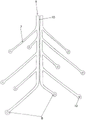
Figure 7 shows the stent structure in an expanded form.
Detailed Description
In fig. 1, a device 1 according to the invention is shown in a side view, inside a blood vessel 6. The device 1 has a stent structure 2 and is provided with an insertion aid 3 in the form of a guide wire. The stent structure 2 is shown here implanted in its expanded form in a blood vessel 6. The stent structure 2 is advanced within the microcatheter 4 from the proximal side (here: left side) to the distal side (here: right side); by advancing the micro-catheter 4 or retracting the stent structure 2, the structure is folded again so tightly that it can be accommodated in the micro-catheter 4 for removal from the vascular system together with the micro-catheter. The micro-catheter 4 itself is guided through another catheter 5 with a larger lumen.
The stent structure 2 is provided with struts 7, the struts 7 being substantially annular in pairs and intended to be placed in position against the inner wall of the blood vessel 6. In addition, the strut 7 is provided with an electrical conductor which is connected to an electrode 8 at the end of the strut 7. For each ring of struts 7 there are pairs of electrodes 8 belonging to each other, between which a small gap is provided, through which a pulse, for example an electrical pulse or an HF pulse, can be applied to the surrounding tissue. Furthermore, it can be seen that for each ring formed by struts 7, the electrode pairs 8 and hence the gaps between the electrodes are offset from each other with respect to their position in the periphery of the blood vessel, i.e. different rings of struts 7 apply pulses at different radial positions.
Fig. 2 is an enlarged view of the support structure 2 shown in fig. 1. It can be seen that each strut 7 forms a split ring in pairs, with an electrode 8 arranged at the end of each strut 7. For the individual rings of struts 7, which are arranged one behind the other in the longitudinal direction, the electrodes 8 are arranged offset from one another. The pulses intended to act on the different radial regions of the vessel wall and the nerve fibers extending therein may be emitted simultaneously, but the emission may also occur offset in time. For a particular loop of struts 7, the location at which pulse application is to take place can also be selected, for example, by suitably moving the stent structure 2 in the longitudinal direction.
The struts 7 originate from a common ridge 9 extending in the longitudinal direction of the stent structure 2. In the arrangement shown here, the spine 9 itself may be divided into two parts, such that one half of the spine 9 is used to supply power to a first half of the strut 7, and a second half of the spine 9 is used to supply power to a second half of the strut 7.
In fig. 3 is shown a partial cross-section of the support structure 2 shown in fig. 2; it can be seen how the strut 7 is connected to the ridge 9 and there is an insulator 10 between the two halves of the ridge 9, which ensures that no short circuit occurs between the two halves of the ridge 9.
Fig. 4 shows a stent structure 2 which is substantially similar to the stent structure 2 shown in fig. 2, but in which a membrane 11 is arranged on the luminal side, i.e. within the stent structure 2, which membrane separates the actual lumen of the blood vessel 6 from the stent structure 2, thus creating an isolation in the luminal direction.
In fig. 5, two split rings are shown, which are arranged one after the other in the longitudinal direction and are formed by struts 7, each starting from a ridge 9. The ridge 9 is provided with 4 conductors A, B, C, D which ensure the current supply to the electrodes 8. The supply of power via conductor A, B on the one hand and conductor C, D on the other hand can be done simultaneously or sequentially.
Fig. 6 shows the electrode 8 forming the end of the electrical conductor 13. In the embodiment shown here, the electrical power is conducted directly to the electrodes 8 through the struts 7, i.e. the struts 7 are also electrical conductors 13. To visualize the electrode 8, the electrode has an opening inside, into which the radiopaque marker 12 is pressed. For example, the radiopaque markers 12 may be made of platinum or a platinum alloy. In the radiographic image, the attending physician thus immediately recognizes how the electrodes 8 are arranged, and the electrodes 8 emit pulses essential for the treatment. In addition, the physician can verify that no short circuit has occurred between the electrodes 8.
Fig. 7 depicts the stent structure 2 in an expanded form, i.e. the struts 7 forming the split ring are pressed into a planar surface, resulting in the two-dimensional representation shown. It can be seen that the struts 7 have different lengths. In this way, it is achieved that after insertion into the blood vessel, the electrodes 8 are finally arranged on the inner wall of the blood vessel in an offset or staggered manner, so that the pulses are allowed to act on different parts/sections.
Claims (11)
1. A device having a stent structure (2) for insertion into an intracranial vessel (6) in a human or animal body, wherein the stent structure (2) has an expanded state in which it can abut an inner wall of the vessel (6) and a compressed state in which it can be moved through the vessel (6) when the stent structure (2) is positioned within a microcatheter (4), wherein the stent structure (2) is connected to an insertion aid (3), and wherein the stent structure (2) is automatically transformable into the expanded state upon release from the microcatheter (4),
it is characterized in that the preparation method is characterized in that,
the stent structure (2) having electrical conductors (13) by means of which electrical or high-frequency pulses can be applied to nerve fibres extending in the vessel wall of a blood vessel (6) to temporarily or permanently reduce the function of the nerve fibres, allowing the prevention or treatment of vasospasm, and wherein the stent structure (2) has a ridge (9) extending from a proximal end to a distal end, from which ridge (9) struts (7) originate, wherein the struts (7) are arranged in pairs and have electrical conductors (13), and in the expanded state the struts (7) form a circumference of the stent structure (2), wherein pairs of electrical or high-frequency (HF) electrodes (8) connected to the electrical conductors (13) are arranged on the circumference of the stent structure (2) at the ends of the pairs of associated struts (7) in such a way that in the expanded state and implanted in the blood vessel (6), the electrodes (8) at the ends of the pair of associated struts (7) are spaced apart by a gap between the ends of the struts (7) such that an applied current flowing through the gap to the electrodes (8) acts on the inner wall of the blood vessel (6).
2. Device according to claim 1, characterized in that at least some of the struts (7) are formed by partial struts which extend parallel to one another.
3. The device according to claim 1 or 2, characterized in that the electrical conductors (13) converge at the proximal end of the stent structure (2) and are connected to the insertion aid (3).
4. A device according to any one of claims 1-3, characterized in that the electrical conductors (13) are electrically insulated from each other.
5. Device according to any one of claims 1 to 4, characterized in that the electrode (8) is provided with a radiographic marker (12).
6. A device according to any one of claims 1 to 5, characterized in that the carrier structure (2) is provided with several pairs of electrodes (8).
7. A device according to any one of claims 1 to 6, characterized in that the gap between the pairs of electrodes (8) is filled with an electrically insulating material.
8. The device according to any one of claims 1 to 7, characterized in that the stent structure (2) comprises a plurality of substantially annular elements, which are spaced apart in the longitudinal direction of the device (1), each element comprising two electrical conductors (13) belonging to an electrical circuit, wherein the two electrical conductors (13) each terminate in one electrode (8) and the two electrodes (8) are separated from each other by a gap when the device (1) is implanted in the vessel (6) in the expanded state.
9. The device according to any one of claims 1 to 8, characterized in that the electrodes (8) and/or pairs of electrodes (8) are arranged offset with respect to each other in circumference, as seen in the longitudinal direction of the stent structure (2).
10. The device according to any of claims 1 to 9, characterized by means for measuring the electrical resistance.
11. Device according to any one of claims 1 to 10, characterized in that the carrier structure (2) is provided with a membrane (11) on the inside.
Applications Claiming Priority (3)
| Application Number | Priority Date | Filing Date | Title |
|---|---|---|---|
| DE102016116871.8A DE102016116871A1 (en) | 2016-09-08 | 2016-09-08 | Device and method for the prevention and treatment of vasospasm |
| DE102016116871.8 | 2016-09-08 | ||
| PCT/EP2017/072451 WO2018046592A1 (en) | 2016-09-08 | 2017-09-07 | Device and method for preventing and treating a vasospasm |
Publications (2)
| Publication Number | Publication Date |
|---|---|
| CN109952068A CN109952068A (en) | 2019-06-28 |
| CN109952068B true CN109952068B (en) | 2022-08-09 |
Family
ID=59997306
Family Applications (1)
| Application Number | Title | Priority Date | Filing Date |
|---|---|---|---|
| CN201780068679.XA Active CN109952068B (en) | 2016-09-08 | 2017-09-07 | Devices and methods for preventing and treating vasospasm |
Country Status (11)
| Country | Link |
|---|---|
| US (1) | US20200129228A1 (en) |
| EP (1) | EP3509521B1 (en) |
| JP (1) | JP7072751B2 (en) |
| KR (1) | KR20190053871A (en) |
| CN (1) | CN109952068B (en) |
| AU (1) | AU2017324399B2 (en) |
| BR (1) | BR112019004503A8 (en) |
| CA (1) | CA3035865A1 (en) |
| DE (1) | DE102016116871A1 (en) |
| ES (1) | ES2846007T3 (en) |
| WO (1) | WO2018046592A1 (en) |
Families Citing this family (7)
| Publication number | Priority date | Publication date | Assignee | Title |
|---|---|---|---|---|
| JP7267567B2 (en) * | 2018-10-31 | 2023-05-02 | ユニチカ株式会社 | Low dielectric constant polyimide |
| DE102021102458A1 (en) | 2021-01-26 | 2022-07-28 | Phenox Gmbh | coated medical devices |
| EP4284309A1 (en) | 2021-01-26 | 2023-12-06 | Phenox GmbH | Coated medical devices |
| WO2023211819A1 (en) * | 2022-04-25 | 2023-11-02 | Gravity Medical Technology, Inc. | Methods and apparatus for evaluating and treating diseased vessels |
| CN117731943A (en) * | 2022-04-29 | 2024-03-22 | 深圳市应和脑科学有限公司 | Intravascular stent electrode array, preparation method thereof and electrical stimulation system |
| DE102022114767A1 (en) | 2022-06-13 | 2023-12-14 | Phenox Gmbh | Endovascular device with guide wire |
| WO2024018367A1 (en) | 2022-07-22 | 2024-01-25 | Phenox Gmbh | Apparatus and method for treating vasospasm |
Family Cites Families (29)
| Publication number | Priority date | Publication date | Assignee | Title |
|---|---|---|---|---|
| DE69330132T2 (en) * | 1993-07-23 | 2001-11-15 | Cook Inc | FLEXIBLE STENT WITH A CONFIGURATION MOLDED FROM A MATERIAL SHEET |
| US6602248B1 (en) * | 1995-06-07 | 2003-08-05 | Arthro Care Corp. | Methods for repairing damaged intervertebral discs |
| EP1006885B1 (en) * | 1996-10-23 | 2006-09-20 | Oratec Interventions, Inc. | Apparatus for treating intervertebral discs |
| US7198635B2 (en) * | 2000-10-17 | 2007-04-03 | Asthmatx, Inc. | Modification of airways by application of energy |
| US20030158545A1 (en) * | 2000-09-28 | 2003-08-21 | Arthrocare Corporation | Methods and apparatus for treating back pain |
| US8774913B2 (en) * | 2002-04-08 | 2014-07-08 | Medtronic Ardian Luxembourg S.A.R.L. | Methods and apparatus for intravasculary-induced neuromodulation |
| US7653438B2 (en) * | 2002-04-08 | 2010-01-26 | Ardian, Inc. | Methods and apparatus for renal neuromodulation |
| US7231260B2 (en) * | 2004-05-06 | 2007-06-12 | Boston Scientific Scimed, Inc. | Intravascular self-anchoring electrode body with arcuate springs, spring loops, or arms |
| EP1962949B1 (en) * | 2005-12-20 | 2015-02-25 | The Cleveland Clinic Foundation | Apparatus for modulating the baroreflex system |
| US7949409B2 (en) * | 2007-01-30 | 2011-05-24 | Cardiac Pacemakers, Inc. | Dual spiral lead configurations |
| US7925352B2 (en) * | 2008-03-27 | 2011-04-12 | Synecor Llc | System and method for transvascularly stimulating contents of the carotid sheath |
| US9339331B2 (en) * | 2008-12-29 | 2016-05-17 | St. Jude Medical, Atrial Fibrillation Division, Inc. | Non-contact electrode basket catheters with irrigation |
| AU2011252976A1 (en) * | 2010-05-12 | 2012-11-08 | Shifamed Holdings, Llc | Low profile electrode assembly |
| US9408661B2 (en) * | 2010-07-30 | 2016-08-09 | Patrick A. Haverkost | RF electrodes on multiple flexible wires for renal nerve ablation |
| EP2608840B1 (en) * | 2010-08-26 | 2017-10-25 | Acandis GmbH & Co. KG | Electrode for medical applications, system having an electrode, and method for producing an electrode |
| US20120265198A1 (en) * | 2010-11-19 | 2012-10-18 | Crow Loren M | Renal nerve detection and ablation apparatus and method |
| WO2012082822A1 (en) * | 2010-12-15 | 2012-06-21 | Med-El Elektromedizinische Geraete Gmbh | Multichannel cylindrical electrode for nerve stimulation and recording |
| CA2843557A1 (en) * | 2011-08-02 | 2013-02-07 | Samson Neurosciences Ltd | Electrostimulation in treating cerebrovascular conditions |
| CN102949176B (en) * | 2011-08-26 | 2014-11-12 | 苏州信迈医疗器械有限公司 | Catheter having renal nerve mapping function |
| US20130231658A1 (en) * | 2012-03-01 | 2013-09-05 | Boston Scientific Scimed, Inc. | Expandable ablation device and methods for nerve modulation |
| US8612022B1 (en) * | 2012-09-13 | 2013-12-17 | Invatec S.P.A. | Neuromodulation catheters and associated systems and methods |
| EP2732784A1 (en) * | 2012-11-20 | 2014-05-21 | Biotronik AG | High-frequency application device for vascular use, in particular for application of high-frequency energy to the renal arterial wall |
| WO2014189887A2 (en) * | 2013-05-20 | 2014-11-27 | Mayo Foundation For Medical Education And Research | Devices and methods for ablation of tissue |
| EP3019105B1 (en) * | 2013-07-11 | 2017-09-13 | Boston Scientific Scimed, Inc. | Devices for nerve modulation |
| US9204929B2 (en) * | 2013-09-16 | 2015-12-08 | Biosense Webster (Israel) Ltd. | Basket catheter with deflectable spine |
| US20150105772A1 (en) * | 2013-10-14 | 2015-04-16 | Boston Scientific Scimed, Inc. | Devices and methods for nerve modulation |
| CN103750898B (en) * | 2014-01-07 | 2016-02-17 | 先健科技(深圳)有限公司 | A kind of intraluminal ablation catheter |
| DE102014101348B4 (en) * | 2014-02-04 | 2023-04-20 | Acquandas GmbH | Medical device for ablating tissue cells and system including such a device |
| US9820664B2 (en) * | 2014-11-20 | 2017-11-21 | Biosense Webster (Israel) Ltd. | Catheter with high density electrode spine array |
-
2016
- 2016-09-08 DE DE102016116871.8A patent/DE102016116871A1/en not_active Withdrawn
-
2017
- 2017-09-07 BR BR112019004503A patent/BR112019004503A8/en not_active Application Discontinuation
- 2017-09-07 US US16/329,869 patent/US20200129228A1/en active Pending
- 2017-09-07 EP EP17777488.2A patent/EP3509521B1/en active Active
- 2017-09-07 KR KR1020197009523A patent/KR20190053871A/en not_active Application Discontinuation
- 2017-09-07 CA CA3035865A patent/CA3035865A1/en not_active Abandoned
- 2017-09-07 ES ES17777488T patent/ES2846007T3/en active Active
- 2017-09-07 CN CN201780068679.XA patent/CN109952068B/en active Active
- 2017-09-07 WO PCT/EP2017/072451 patent/WO2018046592A1/en unknown
- 2017-09-07 AU AU2017324399A patent/AU2017324399B2/en active Active
- 2017-09-07 JP JP2019512651A patent/JP7072751B2/en active Active
Also Published As
| Publication number | Publication date |
|---|---|
| ES2846007T3 (en) | 2021-07-28 |
| EP3509521A1 (en) | 2019-07-17 |
| AU2017324399B2 (en) | 2022-04-07 |
| CN109952068A (en) | 2019-06-28 |
| JP7072751B2 (en) | 2022-05-23 |
| CA3035865A1 (en) | 2018-03-15 |
| JP2019531118A (en) | 2019-10-31 |
| US20200129228A1 (en) | 2020-04-30 |
| EP3509521B1 (en) | 2020-11-04 |
| BR112019004503A8 (en) | 2023-03-21 |
| BR112019004503A2 (en) | 2019-05-28 |
| WO2018046592A1 (en) | 2018-03-15 |
| KR20190053871A (en) | 2019-05-20 |
| AU2017324399A1 (en) | 2019-05-02 |
| DE102016116871A1 (en) | 2018-03-08 |
Similar Documents
| Publication | Publication Date | Title |
|---|---|---|
| CN109952068B (en) | Devices and methods for preventing and treating vasospasm | |
| US10682178B2 (en) | Shock wave balloon catheter with multiple shock wave sources | |
| JP6317678B2 (en) | Apparatus and method for supporting medical treatment | |
| US20130231658A1 (en) | Expandable ablation device and methods for nerve modulation | |
| US20110264132A1 (en) | Multi-utilitarian microcatheter system and method of use | |
| JP2022046775A (en) | Clot removal surgery device | |
| CN109310506B (en) | Vasospasm treatment | |
| US20180228537A1 (en) | Medical device comprising a balloon-stent assembly and methods of using the same | |
| EP3474755B1 (en) | Electrolytic detachment for implantable devices | |
| JP2021505283A (en) | Recovery of substances from electrically enhanced vascular lumen | |
| US11033294B2 (en) | Method of treatment for aortic dissection | |
| US20230039773A1 (en) | Implant for treating aneurysms | |
| US20230285174A1 (en) | Medical device comprising a balloon-stent assembly and methods of using the same | |
| US11963895B2 (en) | Device for introducing implants | |
| WO2024018367A1 (en) | Apparatus and method for treating vasospasm |
Legal Events
| Date | Code | Title | Description |
|---|---|---|---|
| PB01 | Publication | ||
| PB01 | Publication | ||
| SE01 | Entry into force of request for substantive examination | ||
| SE01 | Entry into force of request for substantive examination | ||
| TA01 | Transfer of patent application right | ||
| TA01 | Transfer of patent application right |
Effective date of registration: 20220722 Address after: Bochum Applicant after: Femtos GmbH Address before: Bochum Applicant before: PHENOX GmbH |
|
| GR01 | Patent grant | ||
| GR01 | Patent grant |