CN1098713C - Improvements in and relating to containers of particulate material - Google Patents
Improvements in and relating to containers of particulate material Download PDFInfo
- Publication number
- CN1098713C CN1098713C CN95193074A CN95193074A CN1098713C CN 1098713 C CN1098713 C CN 1098713C CN 95193074 A CN95193074 A CN 95193074A CN 95193074 A CN95193074 A CN 95193074A CN 1098713 C CN1098713 C CN 1098713C
- Authority
- CN
- China
- Prior art keywords
- funnel
- hole
- container
- flat board
- accumulator
- Prior art date
- Legal status (The legal status is an assumption and is not a legal conclusion. Google has not performed a legal analysis and makes no representation as to the accuracy of the status listed.)
- Expired - Fee Related
Links
- 230000006872 improvement Effects 0.000 title description 3
- 239000011236 particulate material Substances 0.000 title description 2
- 239000000463 material Substances 0.000 claims abstract description 56
- 239000003814 drug Substances 0.000 claims abstract description 36
- 238000000034 method Methods 0.000 claims abstract description 32
- 239000008187 granular material Substances 0.000 claims description 29
- 230000033001 locomotion Effects 0.000 claims description 11
- 238000007789 sealing Methods 0.000 claims description 10
- 239000011148 porous material Substances 0.000 claims description 5
- 230000000694 effects Effects 0.000 claims description 3
- 239000012254 powdered material Substances 0.000 abstract 2
- 239000011888 foil Substances 0.000 description 13
- IJGRMHOSHXDMSA-UHFFFAOYSA-N Atomic nitrogen Chemical compound N#N IJGRMHOSHXDMSA-UHFFFAOYSA-N 0.000 description 12
- 239000007789 gas Substances 0.000 description 8
- 150000001875 compounds Chemical class 0.000 description 6
- 239000012634 fragment Substances 0.000 description 6
- 239000000843 powder Substances 0.000 description 6
- 230000007246 mechanism Effects 0.000 description 5
- 229910052757 nitrogen Inorganic materials 0.000 description 5
- 230000005540 biological transmission Effects 0.000 description 4
- 238000010586 diagram Methods 0.000 description 4
- 230000008569 process Effects 0.000 description 4
- 238000005520 cutting process Methods 0.000 description 3
- 238000009826 distribution Methods 0.000 description 3
- 229940079593 drug Drugs 0.000 description 3
- 230000029058 respiratory gaseous exchange Effects 0.000 description 3
- GUBGYTABKSRVRQ-QKKXKWKRSA-N Lactose Natural products OC[C@H]1O[C@@H](O[C@H]2[C@H](O)[C@@H](O)C(O)O[C@@H]2CO)[C@H](O)[C@@H](O)[C@H]1O GUBGYTABKSRVRQ-QKKXKWKRSA-N 0.000 description 2
- 229910001873 dinitrogen Inorganic materials 0.000 description 2
- 210000003128 head Anatomy 0.000 description 2
- 230000008676 import Effects 0.000 description 2
- 239000008101 lactose Substances 0.000 description 2
- 230000002411 adverse Effects 0.000 description 1
- 208000006673 asthma Diseases 0.000 description 1
- 230000015572 biosynthetic process Effects 0.000 description 1
- 238000001514 detection method Methods 0.000 description 1
- 230000000916 dilatatory effect Effects 0.000 description 1
- 238000005516 engineering process Methods 0.000 description 1
- JEIPFZHSYJVQDO-UHFFFAOYSA-N ferric oxide Chemical compound O=[Fe]O[Fe]=O JEIPFZHSYJVQDO-UHFFFAOYSA-N 0.000 description 1
- 230000006870 function Effects 0.000 description 1
- 230000014509 gene expression Effects 0.000 description 1
- 238000000265 homogenisation Methods 0.000 description 1
- 239000002955 immunomodulating agent Substances 0.000 description 1
- 229940121354 immunomodulator Drugs 0.000 description 1
- 230000002584 immunomodulator Effects 0.000 description 1
- 238000007373 indentation Methods 0.000 description 1
- 238000004519 manufacturing process Methods 0.000 description 1
- 239000003550 marker Substances 0.000 description 1
- 238000005259 measurement Methods 0.000 description 1
- 238000002844 melting Methods 0.000 description 1
- 230000008018 melting Effects 0.000 description 1
- 239000002184 metal Substances 0.000 description 1
- 210000000214 mouth Anatomy 0.000 description 1
- 230000002093 peripheral effect Effects 0.000 description 1
- 230000002265 prevention Effects 0.000 description 1
- 230000009467 reduction Effects 0.000 description 1
- 230000000630 rising effect Effects 0.000 description 1
- 230000035807 sensation Effects 0.000 description 1
- 239000003351 stiffener Substances 0.000 description 1
- 238000003860 storage Methods 0.000 description 1
- 238000004804 winding Methods 0.000 description 1
Images


Classifications
-
- A—HUMAN NECESSITIES
- A61—MEDICAL OR VETERINARY SCIENCE; HYGIENE
- A61M—DEVICES FOR INTRODUCING MEDIA INTO, OR ONTO, THE BODY; DEVICES FOR TRANSDUCING BODY MEDIA OR FOR TAKING MEDIA FROM THE BODY; DEVICES FOR PRODUCING OR ENDING SLEEP OR STUPOR
- A61M15/00—Inhalators
- A61M15/0028—Inhalators using prepacked dosages, one for each application, e.g. capsules to be perforated or broken-up
- A61M15/0045—Inhalators using prepacked dosages, one for each application, e.g. capsules to be perforated or broken-up using multiple prepacked dosages on a same carrier, e.g. blisters
-
- A—HUMAN NECESSITIES
- A61—MEDICAL OR VETERINARY SCIENCE; HYGIENE
- A61M—DEVICES FOR INTRODUCING MEDIA INTO, OR ONTO, THE BODY; DEVICES FOR TRANSDUCING BODY MEDIA OR FOR TAKING MEDIA FROM THE BODY; DEVICES FOR PRODUCING OR ENDING SLEEP OR STUPOR
- A61M15/00—Inhalators
- A61M15/0028—Inhalators using prepacked dosages, one for each application, e.g. capsules to be perforated or broken-up
- A61M15/003—Inhalators using prepacked dosages, one for each application, e.g. capsules to be perforated or broken-up using capsules, e.g. to be perforated or broken-up
- A61M15/0033—Details of the piercing or cutting means
-
- B—PERFORMING OPERATIONS; TRANSPORTING
- B65—CONVEYING; PACKING; STORING; HANDLING THIN OR FILAMENTARY MATERIAL
- B65B—MACHINES, APPARATUS OR DEVICES FOR, OR METHODS OF, PACKAGING ARTICLES OR MATERIALS; UNPACKING
- B65B1/00—Packaging fluent solid material, e.g. powders, granular or loose fibrous material, loose masses of small articles, in individual containers or receptacles, e.g. bags, sacks, boxes, cartons, cans, or jars
- B65B1/04—Methods of, or means for, filling the material into the containers or receptacles
- B65B1/16—Methods of, or means for, filling the material into the containers or receptacles by pneumatic means, e.g. by suction
-
- A—HUMAN NECESSITIES
- A61—MEDICAL OR VETERINARY SCIENCE; HYGIENE
- A61M—DEVICES FOR INTRODUCING MEDIA INTO, OR ONTO, THE BODY; DEVICES FOR TRANSDUCING BODY MEDIA OR FOR TAKING MEDIA FROM THE BODY; DEVICES FOR PRODUCING OR ENDING SLEEP OR STUPOR
- A61M2202/00—Special media to be introduced, removed or treated
- A61M2202/06—Solids
- A61M2202/064—Powder
Landscapes
- Health & Medical Sciences (AREA)
- Engineering & Computer Science (AREA)
- Life Sciences & Earth Sciences (AREA)
- Animal Behavior & Ethology (AREA)
- Anesthesiology (AREA)
- Biomedical Technology (AREA)
- Heart & Thoracic Surgery (AREA)
- Hematology (AREA)
- Bioinformatics & Cheminformatics (AREA)
- Pulmonology (AREA)
- General Health & Medical Sciences (AREA)
- Public Health (AREA)
- Veterinary Medicine (AREA)
- Mechanical Engineering (AREA)
- Medical Preparation Storing Or Oral Administration Devices (AREA)
- Basic Packing Technique (AREA)
- Processes Of Treating Macromolecular Substances (AREA)
- Containers And Packaging Bodies Having A Special Means To Remove Contents (AREA)
- Packages (AREA)
- Vacuum Packaging (AREA)
- Filling Or Emptying Of Bunkers, Hoppers, And Tanks (AREA)
- Materials For Medical Uses (AREA)
- Physical Or Chemical Processes And Apparatus (AREA)
- Closures For Containers (AREA)
- Supplying Of Containers To The Packaging Station (AREA)
- Glass Compositions (AREA)
- Superconductors And Manufacturing Methods Therefor (AREA)
- Transition And Organic Metals Composition Catalysts For Addition Polymerization (AREA)
Abstract
A method of producing a container (201, 231, 350) having a plurality of apertures (eg 202, 232, 352) each containing a respective dose of powdered material, such as a medicament, involves placing an empty container in a position in which its apertures communicate with a reservoir (216, 84) of powdered material. The material is then passed, for example by the flow of gas, from the reservoir into the apertures to fill the latter, and the container is then separated from the reservoir and the apertures are optionally sealed with sheet material (204, 206, 321, 323). Since the apertures are filled, their volume determines the amount of each dose which therefore does not have to be measured prior to introduction into the apertures. The container may comprise a rigid or flexible plate and in latter case can be subsequently rolled into the form of a cylinder for use in an inhaler. Apparatus for performing the method, and an inhaler for use with a cylindrical container, are also disclosed.
Description
Technical field
The method that the present invention relates to container is provided and be contained in many parts of individually dosed granular materials (especially powdery medicine) wherein, and relate to the device of implementing this method.The present invention is specially adapted to take by inhalation the device of the powdery medicine of single dose.
Background technology
Knew already, and took voluntarily by inhalation and get very thin, graininess pharmacology class reactive compound, can alleviate problem, the especially asthma of breathing aspect.
This compounds can be contained in the container, and each container has a plurality of material chamber, the indoor chemical compound that corresponding dosage is housed of each material.These containers are used for linking to each other with an inhaler, and this inhaler discharges each immunomodulator compounds successively.For example, European patent specification EPO211595 number (Glaxo Group Co.,Ltd) has been showed a kind of inhaler, and wherein granular material is from dish bubble Bao Qunzhong administration.
Bubble bag in the dish is equipped with powder by means of filling head, and the chemical compound that this filling head will come out in the accumulator is divided into independent dosage and these dosage are flowed in the bubble bag.The constant error of every part of medicament and make powder have the requirement of suitable flow behavior to enable to fill during measurement causes this chemical compound to have to mix with the lactose of larger amt.
This makes, and the required volume of each independent bubbles bag increases in the container, thereby makes the container of an intended size can send out the umber minimizing of medicine.In addition, user must suck the powder of relative greater number when taking medicament voluntarily, and this can make the oral cavity of user and throat produce offending sensation.
FR-A-2667790 discloses movement that a plurality of low dose of powder are housed and the manufacture method thereof that is used for powder inhalator.Inhaler has a respiration channel.Movement has a band, and this is with and is installed with a plurality of eyelets, and these eyelets also all are filled with powder equably at interval.Described tape winding is in a storage housing, and movement has the passage that is communicated with the respiration channel of inhaler when it is used for inhaler.
Summary of the invention
According to a first aspect of the present invention, the method that provides a kind of filling to have the container of a plurality of material chamber, it is indoor that the scheduled volume granular material of some dosage is placed on these material, and this method may further comprise the steps:
1. each material chamber is brought into and held the position that accumulator that the excess granular material is arranged is connected;
2. make material enter and fill up the material chamber; And
3. will expect that chamber and accumulator separate, wherein each material is indoor is equipped with corresponding dosage, the capacity of each material chamber has determined the wherein dosage of the medicament of institute's splendid attire, it is characterized by: the gas pressure that acts on the accumulator endoparticle shape material forces granular material to flow into by in the formed material of the hole chamber in the flat board, container is bearing on the porous backing plate, and this backing plate allows gas to stop granular material to pass the hole discharge by hole.
Granular material is preferably powdery medicine, the particularly the sort of medicine that uses inhaler to take voluntarily by inhalation.
Because the dosage of every part of material is to be measured effectively by the material chamber of container, the needs of each dosage have been avoided before filling containers, measuring, therefore more accurate to the control of the quantity of each material indoor material, reduce or avoided needs any suitable heavy addition material (for example lactose).Therefore, container can be shaped as and hold more relatively dosage.When taking this class medicament voluntarily, user needn't suck a large amount of granular materials.
Preferred version is: each expects that the chamber together is brought into a position that is communicated with common accumulator.
The use of gas provide to granular material is pressed in the hole pressure and therefore to the additional control of the density of material.
Preferred version is: backing plate comprises the dull and stereotyped and meticulous porous material (for example filter paper) of one deck of a porous basic unit, and this porous material in use is inserted between basic unit's flat board and the container.
Thereby in a single day hole is filled preferably to be sealed each dosage is encapsulated in the corresponding perforations individually, can realize described sealing easily by the corresponding layer material that bonds of the two sides at flat board.
Preferred version is: the layer material of sealing hole is made of a laminated thin sheet, and it is connected on the main body by heat-sealing.
Destroyed when allowing material to discharge from hole when the sealing of certain hole, laminated foil helps to prevent the remainder disconnection of part with the thin slice of thin slice.
Flat board can be flexible, and in the case, this method preferably includes following step: after in a single day flat board fills up, promptly be curled (or otherwise being shaped) is a cylinder.
By an annular end cap is contained on the container, container can remain the shape of cylinder, normally two described end caps respectively is used for an end of cylinder.
Such flat board preferably comprise one group elongated and flat, be essentially inflexible rectangular, a pair of rectangular adjacent is can be reduced relative to each other, therefore in the container of making, these rectangular axis with cylinder are substantially parallel.
Possibility is, flat board can constitute some rectangular one of them, these rectangular being assembled together constitute cylindric combination containers.
Preferred version is, accumulator is contained in the funnel with one group of discharge opening, and when hole was positioned at described position with respect to accumulator, each discharge opening was aimed at corresponding perforations, and, be used for making granular material to pass discharge opening and go forward side by side into hole to the gas of the enough pressure of funnel supply.
Preferred version is that the size of discharge opening makes when not to the funnel gas transmission, do not have granular material therefrom to pass through basically.
Like this, by cutting off gas transmission, flat board can be removed and without any of the bottom leakage of relatively large granular material from funnel to funnel.
According to a second aspect of the invention, the equipment that is used to implement the method for first aspect present invention comprises: one can flatten the porous backing plate that put thereon with flat board; Be used for filling head to the upper surface conveying granular material of flat board; Be used for making air or gas to flow through hole on the flat board and backing plate so that granular material sucks the device of hole.
Preferred version is, filling head comprises a funnel with a series of discharge openings, and the position of the hole on the relative position of discharge opening and the flat board is corresponding, thereby when below flat board is positioned at funnel, each discharge opening is aimed at corresponding perforations.
Preferred version is that this equipment comprises: height detecting device is used to detect the height of staying the granular material in the funnel; And the device that is used for carrying more granular materials to funnel.
If funnel is elongated, then the preferred arrangement of feeding device and height detecting device is: the end at funnel is carried material, and height detecting device detects the material height of end opposite in the funnel, and this equipment also comprises the distribution apparatus that is used to make funnel endoparticle shape material homogenization.
Description of drawings
Referring now to the following drawings the present invention is described exemplarily:
Figure 1A-1H is a rough schematic view, illustrates each step of the method for making a cylindrical vessel.
Fig. 2 A-2E illustrates the member of a kind of optional form of the cylindrical vessel that can be filled up by the method shown in Figure 1A-1H, and Fig. 2 E illustrates this container after the assembling.
Fig. 3 is the plane graph that is used to implement the equipment of this method improvement project, and this equipment is placed with several stations around turntable, implements each step on these stations.
Fig. 4 is the generalized section of the sagittal plane of described first station.
Fig. 5 is described second station of diagram and in the generalized section of the sagittal plane of the step that this station carried out.
Fig. 6 is by the second similar view to the part of the 3rd station transmission along turntable.
Fig. 7-11 is the 3rd station radial section figure in each operational phase.
Figure 12-16 is the local radial profile of the 4th station in each operational phase.
Figure 17 and 18 is the similar view of described the 5th station.
Figure 19 is the similar view of the 6th station.
Figure 20 illustrates the part of the 7th station.
Figure 21 has shown by the outlet of the 7th station to the transmission of the 8th station.
Figure 22 is the isometrical drawing of an inhaler after cutting away part, and this inhaler is used for Powdered medicament is provided away from the container of making, and this container has formed a part that is encapsulated in the core tube in the inhaler.
Figure 23-26 is the exploded isometric view of each part of core tube.
Figure 27 shows the core tube that assembles.
Figure 28 is the partial exploded view of core tube and shell.
Figure 29 A-29F is a generalized section, and the part of diagram inhaler is in the working condition in each stage of its working cycle.
Figure 30 A-30F is a profile, and other parts of this equipment of diagram are in the working condition in corresponding each stage of working cycle.And
Figure 31 is the side view of an element of inhaler.
Figure 32 is the end-view of this element.
Figure 33 is the being seen view in container front from an optional form, and this container also can be filled according to method of the present invention.
Figure 34 shows a thin portion of this container, and
Figure 35 is the side view of this container.
The specific embodiment
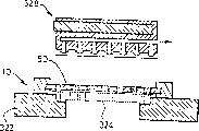
With reference to Figure 1A-1H, container is made of a main body 201, and this main body comprises many through holes (as through hole 202), is used for the medicine of splendid attire corresponding dosage.For clarity sake, in Figure 1A-1H, only illustrate 20 this through holes on the main body, and in fact can have the through hole of greater number on the main body 201.
In the container of making, main body 201 is roughly cylindrical shape, and radially arrange in these holes and the outer thin slice 204 and the interior thin slice 206 that are heat-sealed in the laminated foil on the main body 201 are sealed.
With reference to Figure 1A, main body 201 is made of the rectangular flat of a plastic material, and its downside is placed with many grooves 208 in the parallel array mode of rule.It is rectangular that groove 208 is divided into several parallel rigidity across crossing this dull and stereotyped overall with this member, as rectangular 210.Adjacent a pair of rectangular part by the corresponding attenuate of thickness (as part 212) couples together.The thickness that constitutes the plastic material of these parts makes adjacent rectangular can amounting to relative to each other.Through hole on the main body 201 all be located at rectangular in.
Dull and stereotyped 201 lie on the backing plate 214 of being made by porous material, and main body does not have one of groove to face up, and dull and stereotyped 201 upper surface is covered by one deck powdery medicine 216, and these medicines have covered an end of each through hole.
With reference to Fig. 1 C, logical downwards then nitrogen passes the medicine layer 216 in the through hole, passes backing plate 214 again, and material 216 is flow in each through hole.The vesicularity of backing plate 214 makes not porous of material 216.Consequently: backing plate 214 stops material 216 to flow out from the bottom of through hole.
After through hole is filled up by material 216,, there is not the excess stock in the inspiration through hole to remove (Fig. 1 D) those by dilatory springy flexible scraper plate 218 across dull and stereotyped 201 upper surfaces.With the upper surface (Fig. 1 E) of thin slice 204 heat-sealings, thin slice 206 similarly can be spread on the reverse side (Fig. 1 F) of flat board 201 then thereby then flat board is overturn at flat board 201.
By on dull and stereotyped 201 each rectangular between the formed flexibility of part that reduces of thickness, make flat board can be rolled into (Fig. 1 G) cylindrical shape roughly, each is rectangular extends along the cylinder axis direction, groove 208 is positioned at its inner surface.
Two annular end caps 220 and 222 are connected in each end of cylinder respectively.Each end cap comprises a circular orbit (for example track 224), and rectangular reaching also forms tight fit therein in this track.So end cap 220 and 222 prevents that this cylinder is loose and opens.Element shown in Fig. 2 A-2E is with corresponding shown in Figure 1A-1H, and corresponding element is represented with former numbering increase by 30.So container is made of a main body 231, this main body is rolled into by one flat plate (also being labeled as 231), many through holes (as through hole 232) are arranged on it, employing same procedure as shown in Figure 1 makes fills up powdery medicine in the hole, a dull and stereotyped side is sealed by first laminated foil 234, after upset, then second laminated foil 236 spread on the opposite side of flat board 231.
Therefore as can be seen, main body 231 is more than main body 201 contained through holes (as through hole 232), but than the main body 201 splendid attires medicine of multiple dose more.Each groove (as groove 238) on the flat board 231 is a wedge shape in addition, so that curl.End cap 250 with 252 each all contain radially relative inside groove structure (as inside groove 256 and 258), container can be locked in direction of rotation changes on the core, or is locked in container and will be used for wherein inhaler.
As Fig. 2 A as seen, the distribution form of through hole makes it on the spiral path that is positioned at after the container assembling on the main body 231.
Equipment shown in Figure 3 contains a turntable 1 and centers on 8 station 2-9 of its circumferential registration.In use, turntable rotates in a counter-clockwise direction, and as described below the element on the conveyer belt is sent to each station successively.
With reference to Fig. 4, this equipment comprises a jig 10, is used for releasably clamping the container of rectangular flat form.Jig 10 has the first rectangular frame part 12, and this part has inner rim rectangular flange 14, and it limits an orthogonal central opening 16.Hold a porous metal derby 18 in this opening.Jig 10 also includes second rectangular frame 20, and it is rotatably installed on the framework 12, and a periphery flange 22 and a central opening 24 are also arranged on it, and jig 10 releasably is connected on the turntable 1 by an a band mouthful flat board 26.
As shown in Figure 4, station 2 comprises a block 28 with central passage 30, and this passage communicates with two legs 32 and 34.Passage 30 is connected on the vacuum source alternatively, and block 28 is fixed on an air rammer and the cylinder assembly 38, and this assembly can be operated the rising and the reduction of block 28.Piston and cylinder assembly 38 itself is suspended from upper platform 40 (Fig. 3) by the driving device (not shown), but this driving device operating assembly 38 move radially, thereby mobile block 28.
At the radial outer end of station 2 spool 42 of a filter paper is housed, it comprises a drift and die mechanism (not shown), is used for filter paper is cut into Len req.
In use, block 28 is fetched a filter paper section from the radial outer end of station 2, to passage 30 evacuation this section is remained on leg 32 and 34, and it radially inwardly is transported to position shown in Figure 4, then filter paper is dropped on the block 18.Cut off vacuum subsequently, thereby after block raise, filter paper was stayed still in the jig 10.
On turntable 1 jig 10 is sent to station 3 then, Fig. 5 is more detailed diagram.Station 3 has one to be fixed on pneumatic gripping 44 on the upper platform 46 by air rammer and cylinder assembly 48, in use, clamp 44 is collected container 50 from the material storehouse 52 that is positioned at station 3 radial outer ends, container 50 is transported to position shown in Figure 5 and places it on the filter paper in the jig 10 (being designated as 54).Clamp 44 is removed then, and framework 20 is reduced to above the framework 12, thereby filter paper 54 and container 50 are clamped between flange 14 and 22.Container 50 contains a flexible flat, and this flat board has one group of hole, and one of them is designated as 56.Container shown in this container and Figure 1A and the 2A is similar.
Afterwards, wherein clamping has the jig (as shown in Figure 6) of container and filter paper to be transferred to filling station 4 shown in Figure 7.In Fig. 6 to 21, for clarity sake, jig 10 illustrates in simplified form.
Fill station 4 and comprise a filling head 59, this has the rectangular air inlet pipe 58 that communicates with pipeline 60, can optionally provide pressure nitrogen gas for air inlet pipe by pipeline 60.Air inlet pipe 58 is enclosed on the rectangle upper strata frame part 62 by an O RunddichtringO 64.Part 62 has the center rectangle opening, the bubbler 64 that holds a porous block in this perforate, periphery rectangular frame part 66 is trapped among around the part 62, and define first stomidium with part 62, this pore volume is received a charging inclined tube 68, in use, powdery medicine is carried along this inclined tube from advancing feeder 70 through valve 72. Framework 62 and 66 also defines a perforate relative with described inclined tube 68, is used to hold a ultrasonic height sensors 74.Contain another hole in peripheral frame one side, stretch out a push rod 76 by this hole.One end of push rod is connected with a rectangle scraper plate 79, and the direction that its long axis extends is basic vertical with the plane of Fig. 7.
Import nitrogen by pipeline 60 then, nitrogen passes the hole of material 84 and funnel 78 bottoms by a bubbler 64 (preventing that stream of nitrogen gas from producing adverse effect to the distribution of granular materials 84), passes the interior hole of container 50 again.The nitrogen that exists in the hole of container 50 enters block 18 through filter paper 54.This one stroke of nitrogen impels powdery medicine 84 to pass hole on the funnel 78 to enter in the hole in the container 50, and filter paper 54 stops powdery medicines to be discharged from the bottom of hole.
Thereafter as shown in figure 11, filling head 59 is raised from container 50, injects other a collection of powdery medicine in the funnel in order to fill next time, uses scraper plate 79 drawouts when needing.Container 50 and its jig 10 of filling up subsequently are transported to station 5 by turntable 1, spool 300 and feed arrangement (not shown) that laminated foil coiled material 302 is arranged at this station radial outer end, feed arrangement is used for sending drift 302 and punch die 304 with thin slice from spool, and this punch die is limited with an orthogonal hole.Seal head 306 is contained in the same end of station 5, aims at the hole that punch die 304 is limited by the assembly (not shown) of air rammer and cylinder, and this assembly can be operated raising of seal head 306 and reduce.
With reference to Figure 13, drift 302 also is fixed on the air rammer air cylinder device (not shown), and this device can be operated the lifting of drift 302, makes it from the next rectangular segments 313 of thin slice 301 long section cuttings, and this fragment moves up, and contacts with seal head 306.At this moment, passage 314 is communicated with vacuum source, causes each footing on the seal head 306 that fragment 313 is adsorbed.
Thin slice coiled material 301 is wideer than fragment 313, consequently: when drift 302 is got back to position shown in Figure 13, a new thin slice fragment is pulled to the position of drift 302 tops by the reel assembly (not shown), this reel assembly is positioned the right side of element shown in Figure 12, is a side opposite with those elements of spool 300.
Piston and cylinder assembly that seal head 306 is installed on it are installed on the top platform 316 (Fig. 3) through a driving mechanism, and this driving mechanism is used at both direction hydrodynamic reciprocating sealing head 306 radially.Like this, after section 313 was attached on the seal head 306, this was elevated to position shown in Figure 15, and driving device operation seal head radially is moved into position shown in Figure 16, is positioned the top of container 50.
Then as shown in figure 16, seal head 306 drops to above the container 50.Section 313 laminated foil has upper strata (contacting with 306 footing), the heat effects that this upper strata is not subjected to heater is basically sent.Yet the orlop in the laminated foil is heat-sealed on the container 50 section 313 by the heat local melting that heater 308 is sent.Passage 314 disconnects with vacuum source then, and position shown in Figure 12 is got back in 306 lifting, and the one side of container 50 is sealed by the laminated thin sheet.
With reference to Figure 17, container 50 and jig 10 thereof are sent to station 6 then, throw off and place on the rest pad 320 from turntable at this station upper container 50, support 10 and dull and stereotyped 18.Similar then rest pad 322 and porous plate 324 place the top of container 50 and jig 10.Rest pad 320 links to each other with mechanism's (not shown) with 322, and this mechanism overturns parts shown in Figure 17 in the mode shown in the arrow among Figure 18 326, thereby rest pad 320 is positioned at topmost.Parts shown in Figure 180 then are sent to station 7, and this station contains a stature (not shown), and this releasably catches the top of rest pad 320, and have along the vacuum device of dull and stereotyped 324 sealings, and filter paper 54 is sucked positioned against on dull and stereotyped 18.Then, this headband rest pad 320, flat board 18 and filter paper 54 and is removed from container 50, as shown in figure 19.
Therefore then, the parts that stay shown in Figure 19 are sent to station 8, and the form of this station is similar to station 5 to function, comprise the spool 326 of a laminated foil, laminated foil be admitted to drift and punch die 304 drift and die assembly similar to 302 in.Drift and punch die downcut a fragment of laminated foil, spread on then with 306 identical type 328 on.By one with at station 5 seal heads 306 employed similar devices are installed, should 328 be installed on station 7, thereby this 328 can move radially position shown in Figure 20, be in container 50 directly over.This head descends then, and the section of laminated foil is enclosed on the container 50.
Figure 21 show still stay in the jig 10, be in and fill up and the container 50 of seal form.Laminated foil is denoted as 321 and 323.With this form, container 50 and jig 10 are sent to station 9, throw off jig 10 at this station container 50, and are rolled into cylindric with the similar fashion of method noted earlier.
With reference to Figure 22, the inhaler that container 50 can be used on wherein comprises a shell 100, and this shell has one section roughly to be cylindric part, links to each other with a suction nozzle 102 in its lower end, and the main part of this suction nozzle and shell 100 is substantially vertically stretched out.Shell 100 opposite ends contain the knob spare that is cover cap 104 forms, and this cover cap is rotatably installed on the other end of shell 100, and a window 106 is housed on the cover cap 104, can see the core tube 108 of institute's splendid attire in the housing 100 by this window.
With reference to Figure 23 to 26, core tube 108 comprises the cylindrical cartridge 110 of a sky, and the diameter on this fuse top 112 is less, and this part has upper end hole 114 and integrally formed ratchet 116.Fuse 110 also comprises lower part 118, and this part is bigger than the diameter on top 112, and is forming annular shoulder 120 with 112 intersections, top.Part 118 includes: external screw thread 122, radial hole 124 and two lower protrusion of axially stretching out 126 and 128 in the zone at an upper portion thereof.
Accommodate a vertical axes 130 in the fuse 110, stretch out from hole 114 on its top.A groove 132 is arranged at axle 130 top, is used for the outthrust 136 of cover cap 104 top downsides chimericly, rotates key thereby form between axle 130 and cover cap 104.A radially crank 138 is equipped with in axle 130 bottom, and this crank contains the radial slot 140 with protruding 142 sliding gomphosis, and projection 142 links to each other with the pricker 144 that is positioned dull and stereotyped 146 tops.Pricker is aimed on the housing 110 and hole 124 angled isolated another hole (not shown).
After the core wound packages prepares, adopt the proper device (not shown) that flat board 146 is installed in the fuse, pricker 144 and dull and stereotyped 146 contains the guider (not shown), and the arrangement of this guider makes the rotation of axle 132 can cause pricker 144 axially-movables.Referring to Figure 25, sleeve 150 of shoulder 120 supporting, this sleeve are rotatably installed on the fuse 110 and around the top 112 of fuse.
With reference to Figure 25, the medicine of dispensing to be contained in the cylindrical container 158, this container side wall contains the radial direction through hole of many helical arrangement, as through hole 159 (Figure 22), the material of suitable dosage is housed in each through hole.The inside and outside surface coverage of this sidewall has corresponding laminated foil, seals the two ends in each hole.Container 158 is made by aforementioned any one method.
Fuse 110 stretches out from the center of container 158, and container 158 comprises: have the lower endcaps 160 of local spiral groove (not shown), this groove is used for and screw thread 122 engagements; With upper end cap 162, it contains two groups of opposed grooves 164 of diametric(al) and 166, and they and rib 154 and 156 groups of tablings form rotatable key between sleeve 150 and container 158.
The top of axle 130 has the shoulder 133 of supporting pawl component 168, and this pawl component can rotate with respect to axle 130.Pawl component 168 includes top projection 170, and this projection embeds in the arc track 172 (Figure 29 A) of cover cap 104 downsides, makes and forms decalage motion connection between cover cap 104 and the pawl component 168.
As shown in figure 28, cover cap 104 can be pulled down from the other end of housing 100, the core tube 108 (as shown in figure 27) that assembles can be inserted in the shell 100, lower protrusion 126 and 128 (Figure 23) up to fuse 100 embeds in the corresponding jack 174 in shell 100 bottoms and 176, forms rotatable key between fuse 110 and shell 100.
As shown in figure 28, shell 100 comprises a upper notch 178, and its formation stop device that matches with outstanding downwards projection (not shown) on the cover cap 104 defines cover cap 104 and allows the scope of rotating with respect to the other end of shell 100.
Inhaler includes the gas circuit of representing with marker arrow, and it extends upward from air intake 180, through fuse 110, through perforate 124 and with the aligned through hole that a medicament is housed of this perforate, then through exit passageway down to the outlet 182.For sucking-off medicament from inhaler, user must forward cover cap 104 to another extreme position from an extreme position, and then go back to, make pricker 144 puncture the thin slice that seals of a through hole, and this through hole is moved to and the aligned position of exit passageway subsequently.Referring now to Figure 29 A-29F and Figure 30 A-30F this operation is described in more detail.
Figure 29 A shows the dispensing device that is in original state, wherein pricker 144 be indentation and all material chambers be sealing.Clockwise direction turning knob 104 shown in arrow 184 among Figure 29 B, the 130 corresponding rotations of feasible axle, this axle 130 then drives crank 138 and rotates, thereby pricker 144 is stretched out, up to it penetrate hole 186 in seal (Figure 30 B), arcuate groove 172 is with respect to projection 170 motion in this process, thereby prevents that pawl component 168 from rotating, up to projection 170 with till the tail end of groove 172 contacts.Along the further turning knob 104 of equidirectional, cause also correspondingly rotation of pawl component 168 then, this member can only rotate with respect to sleeve 150 clockwise directions.At this moment, ratchet 116 rotates with chimeric prevention sleeve 150 counter-clockwise direction of the zigzag medial surface of sleeve 150.When tolerance limit that arrival turns clockwise, member 168 is positioned at position shown in Figure 29 C, and pricker 144 is positioned at position shown in Figure 30 C, and in this position, pricker stretches out and passes and pass hole 186, thereby pierces through inside and outside sealing.
Shown in Figure 29 D, backward rotation knob 104 makes pricker 144 return from hole 186 and removes then.Remove in the process for 144 times at pricker, arcuate groove 172 moves with respect to projection 170, thereby prevents the corresponding sports (thereby preventing container 158 motions) of sleeve 150, till pricker is removed for 144 whole times.Further counter-clockwise direction turning knob 104 rotates member 168, and chimeric by projection 170 and groove 172 causes the rotation of sleeve 150 again.Because sleeve and container 158 connect with rotatable key, so this motion causes container 158 to rotate at 118 places, bottom of fuse 110, and owing to the engagement of cover cap 160 and screw thread 122, above-mentioned motion makes the path movement of through hole (comprising through hole 186) along local spiral again.When knob 104 arrived the tolerance limit of inhour rotation, shown in Figure 29 F, hole 186 had been aimed at exit passageway (Figure 30 F).
Afterwards, if user is air-breathing by the outlet 182 of suction nozzle 102, then the air-flow of this device of process that thereupon produces spurts medicine in the outlet plenum and through exporting 182 from hole 186.
With reference to Figure 22 3, suction nozzle 102 also comprises a grid 190, is used for tackling any fragment that is scattered that seals thin slice that floats in suction process.
An optional form that is used for the container of powdery medicine is shown in Figure 33, and it is made of an independent stiffener plate 350, and this flat board has the centrage that contains 10 holes (as hole 352), holds the medicine of corresponding dosage in each hole.These holes are sealed by two thin slices, and one of them is to number 354 expressions, and thin slice stretches along dull and stereotyped 350 opposite sides.Other two rounds 356 and 358 are positioned at the both sides that medicine holds the hole, and this two round in use helps dull and stereotyped 350 location.
When thereby the quantity in hole and position are corresponding on quantity that makes hole on the funnel when Fig. 3-21 apparatus shown is made amendment and position and container 350 centrages, dull and stereotyped 350 centre bore can be filled by this equipment, and amended equipment has saved the scrolling station 9 in the aforementioned device.
Claims (14)
1. filing of containers (201; 231; 350) method, this container have several material chambers (56 that separates; 202; 232; 252), be placed with the granular material of some doses of scheduled volumes in it, this method may further comprise the steps:
A. with each material chamber (56; 202; 232; 252) bring and be equipped with the accumulator (216 of excess granular material into; 84) position that is connected;
B. make material enter and fill up material chamber (56; 202; 232; 252); And
C. the material chamber (56 that will fill up; 202; 232; 252) with accumulator (216; 84) separately, wherein every doses is contained in the corresponding material chamber, the capacity of each material chamber has determined the wherein quantity of the dosage of institute's splendid attire, it is characterized by: the gas pressure that acts on the accumulator endoparticle shape material forces granular material to flow into by in the formed material of the hole chamber in the flat board, and container is bearing in a porous backing plate (214; 54; 18) on, this backing plate allows gas to stop granular material to pass the hole discharge by hole.
2. according to the described method of claim 1, it is characterized by: granular material is a powdery medicine, and this powdery medicine is used for taking by inhalation.
3. according to claim 1 or 2 described methods, it is characterized by: before filling, each material chamber (56; 202; 232; 252) be brought to one and public accumulator (216; 84) on the position that is communicated with simultaneously.
4. according to claim 1 or 2 described methods, it is characterized by: described flat board makes with relative motion between the accumulator expects that respectively the chamber is connected with accumulator.
5. according to claim 1 or 2 described methods, it is characterized by: this backing plate (54; 18) comprise a Porous Base (18), one deck poromerics (54) is arranged on it, this layer material is discarded after use.
6. according to claim 1 or 2 described methods, it is characterized by: material chamber (56; 202; 232; 252), thereby each dosage is packaged in the corresponding material chamber individually in case fill up promptly and be sealed.
7. according to the described method of claim 6, it is characterized by: described flat board makes with relative motion between the accumulator expects that respectively the chamber is connected with accumulator; Described sealing is to realize by bonding layer of material on each face of flat board.
8. according to the described method of claim 7, it is characterized by: flat board is flexible, and is curled after filling or is configured as a cylinder by alternate manner.
9. according to claim 1 or 2 described methods, it is characterized by: accumulator (78) is contained in the funnel, and this funnel has one group of discharge opening (82), each Kong Yuyi corresponding material chamber (56; 202; 232; 352) aim to be used for filling, carry described gas to funnel, enter in the hole (56) in order to force granular material to pass discharge opening (82) with enough pressure.
10. according to the described method of claim 9, it is characterized by: the size of selected discharge opening (82) unless make outside its effect that is subjected to gas pressure, can stop granular material therefrom to pass through.
11. be used to implement the equipment by the described method of claim 1, it is characterized by: this equipment comprises the backing plate that is made of porous materials (214 that flat board can be kept flat thereon; 54; 18), be used for filling head (59), and be used for making air or gas to pass hole in dull and stereotyped and backing plate and force granular material to enter device in the described hole to the upper surface conveying granular material (84) of flat board.
12. according to the described equipment of claim 11, it is characterized by: filling head (59) comprises a funnel with a series of discharge openings, the position of the hole on the relative position of discharge opening and dull and stereotyped (50) is corresponding, thereby when below flat board is positioned at funnel, each discharge opening is aimed at corresponding perforations (56).
13. according to the described equipment of claim 12, it is characterized by: this equipment comprises height detecting device (74), be used to detect the height of staying the granular material in the funnel, and comprise the feeding device (70,72) that is used in funnel, carrying more granular materials.
14. according to the described equipment of claim 13, it is characterized by: funnel is elongated, height detecting device (74) and feeding device (70,72) be arranged to, end at funnel (78) is carried material, and in funnel zone far away the height of test material, this equipment also comprises the device (76) that is used for distributed granule shape material in funnel, makes it to reach in funnel the thickness of basically identical.
Applications Claiming Priority (2)
| Application Number | Priority Date | Filing Date | Title |
|---|---|---|---|
| GB9409851A GB9409851D0 (en) | 1994-05-17 | 1994-05-17 | Improvements in and relating to containers of particulate material |
| GB9409851.4 | 1994-05-17 |
Publications (2)
| Publication Number | Publication Date |
|---|---|
| CN1170368A CN1170368A (en) | 1998-01-14 |
| CN1098713C true CN1098713C (en) | 2003-01-15 |
Family
ID=10755262
Family Applications (1)
| Application Number | Title | Priority Date | Filing Date |
|---|---|---|---|
| CN95193074A Expired - Fee Related CN1098713C (en) | 1994-05-17 | 1995-05-16 | Improvements in and relating to containers of particulate material |
Country Status (18)
| Country | Link |
|---|---|
| US (1) | US6226962B1 (en) |
| EP (1) | EP0751795B8 (en) |
| JP (1) | JP3597197B2 (en) |
| KR (1) | KR100347467B1 (en) |
| CN (1) | CN1098713C (en) |
| AT (1) | ATE226101T1 (en) |
| AU (1) | AU697927B2 (en) |
| BR (1) | BR9507731A (en) |
| CA (1) | CA2190497C (en) |
| DE (1) | DE69528579T2 (en) |
| DK (1) | DK0751795T3 (en) |
| ES (1) | ES2187558T3 (en) |
| FI (1) | FI964594A0 (en) |
| GB (1) | GB9409851D0 (en) |
| HU (1) | HU219111B (en) |
| PT (1) | PT751795E (en) |
| RU (1) | RU2141914C1 (en) |
| WO (1) | WO1995031239A1 (en) |
Families Citing this family (38)
| Publication number | Priority date | Publication date | Assignee | Title |
|---|---|---|---|---|
| GB9523555D0 (en) * | 1995-11-17 | 1996-01-17 | Cambridge Consultants | Filling containers with particulate material |
| US5794613A (en) * | 1997-01-09 | 1998-08-18 | Sepracor, Inc. | Multiple-dose dispenser for dry powder inhalers |
| FR2768123B1 (en) * | 1997-09-09 | 1999-11-26 | Soc Generale Pour Les Techniques Nouvelles Sgn | PROCESS AND DEVICE FOR PACKAGING PRODUCTS, SUCH AS POWDERS, ESPECIALLY MAGNETIC |
| GB9911770D0 (en) | 1999-05-21 | 1999-07-21 | Glaxo Group Ltd | Powder loading method |
| GB0023653D0 (en) * | 2000-09-27 | 2000-11-08 | Cambridge Consultants | Device for dispensing particulate material |
| WO2002086427A1 (en) * | 2001-04-20 | 2002-10-31 | Glaxo Group Limited | Metering method for particulate material |
| GB0202912D0 (en) * | 2002-02-07 | 2002-03-27 | Meridica Ltd | Method and apparatus for introducing powder into a pocket |
| GB0207769D0 (en) | 2002-04-04 | 2002-05-15 | Glaxo Group Ltd | Method and apparatus for loading a container with a product |
| JP2006507110A (en) | 2002-06-27 | 2006-03-02 | オリエル・セラピューティクス,インコーポレイテッド | Apparatus, system and related methods for processing, dispensing and / or evaluating non-pharmaceutical dry powders |
| GB0227128D0 (en) * | 2002-11-20 | 2002-12-24 | Glaxo Group Ltd | A capsule |
| WO2005076872A2 (en) * | 2004-02-06 | 2005-08-25 | Microdose Technologies, Inc. | A blister pack for use with an inhalation device |
| DE202005004188U1 (en) * | 2005-03-14 | 2005-05-19 | Harro Höfliger Verpackungsmaschinen GmbH | Device for filling in each case predetermined amounts of powdery filling material |
| US9485917B2 (en) | 2006-12-15 | 2016-11-08 | Ecovative Design, LLC | Method for producing grown materials and products made thereby |
| WO2009008832A1 (en) * | 2007-07-12 | 2009-01-15 | Astrazeneca Ab | Medicament containing structure, method and inhalation device comprising such structure |
| MY187036A (en) | 2010-01-05 | 2021-08-27 | Microdose Therapeutx Inc | Inhalation device and method |
| US8720497B2 (en) | 2010-02-19 | 2014-05-13 | Oriel Therapeutics, Inc. | Direct fill dry powder systems with dosing heads configured for on/off controlled flow |
| US8776840B2 (en) * | 2010-02-23 | 2014-07-15 | Oriel Therapeutics, Inc. | Tubular dry powder feeders with axially applied vibration for dry powder filling systems |
| CN102161384B (en) * | 2011-03-07 | 2012-07-04 | 汪明霞 | Granular grain collecting and storing device |
| US20140056653A1 (en) * | 2012-08-22 | 2014-02-27 | Christopher Scully | Method and Machine for Filling 3D Cavities with Bulk Material |
| CN102795588A (en) * | 2012-08-31 | 2012-11-28 | 常熟市百联自动机械有限公司 | Down filling method of down filling machine |
| CN102815656B (en) * | 2012-08-31 | 2014-07-16 | 常熟市百联自动机械有限公司 | Accurate eiderdown-filling method for eiderdown-filling machine |
| US11277979B2 (en) | 2013-07-31 | 2022-03-22 | Ecovative Design Llc | Mycological biopolymers grown in void space tooling |
| US20150101509A1 (en) | 2013-10-14 | 2015-04-16 | Gavin R. McIntyre | Method of Manufacturing a Stiff Engineered Composite |
| CN105030544B (en) * | 2015-06-20 | 2019-02-15 | 浙江天龙胶丸有限公司 | A kind of capsule fills fitting all-in-one machine automatically |
| SG10201911184TA (en) | 2016-03-01 | 2020-02-27 | Sustainable Bioproducts Inc | Filamentous fungal biomats, methods of their production and methods of their use |
| DE102016119191A1 (en) * | 2016-10-10 | 2018-04-12 | Haver & Boecker Ohg | Filling device for a packing machine for filling bulk goods in containers |
| CN109982935B (en) * | 2016-11-15 | 2021-09-28 | 正大天晴药业集团股份有限公司 | Apparatus and method for powder filling |
| US10414148B2 (en) | 2016-11-16 | 2019-09-17 | United Technologies Corporation | Selective powder dosing for an additively manufacturing system |
| CN110506104B (en) | 2017-03-31 | 2024-02-20 | 生态创新设计有限责任公司 | Solution-based post-processing method for fungal biopolymer material and fungal product prepared thereby |
| US11266085B2 (en) | 2017-11-14 | 2022-03-08 | Ecovative Design Llc | Increased homogeneity of mycological biopolymer grown into void space |
| RU2759489C1 (en) * | 2018-01-31 | 2021-11-15 | Синтегон Текнолоджи Гмбх | Product dosing apparatus |
| US11920126B2 (en) | 2018-03-28 | 2024-03-05 | Ecovative Design Llc | Bio-manufacturing process |
| US11293005B2 (en) | 2018-05-07 | 2022-04-05 | Ecovative Design Llc | Process for making mineralized mycelium scaffolding and product made thereby |
| US11343979B2 (en) | 2018-05-24 | 2022-05-31 | Ecovative Design Llc | Process and apparatus for producing mycelium biomaterial |
| CN109010065A (en) * | 2018-07-30 | 2018-12-18 | 吴霞 | A kind of broken medicine device of multifunctional tumor section |
| EP3860370A4 (en) | 2018-10-02 | 2022-10-12 | Ecovative Design LLC | A bioreactor paradigm for the production of secondary extra-particle hyphal matrices |
| EP3990353A1 (en) * | 2019-06-25 | 2022-05-04 | Mylan Pharma UK Limited | Filling head for powered layering of a dry powder inhaler |
| CN113859656B (en) * | 2021-09-17 | 2023-06-13 | 湖北亿家艾生物科技有限公司 | Eye-shade raw material packaging unit and eye-shade manufacturing equipment |
Citations (3)
| Publication number | Priority date | Publication date | Assignee | Title |
|---|---|---|---|---|
| US3324902A (en) * | 1965-05-26 | 1967-06-13 | Bartelt Engineering Co Inc | Method of filling capsules |
| FR2667790A1 (en) * | 1990-10-04 | 1992-04-17 | Valois | Cartridge for holding small doses of powder in the form of strips designed to be used in a powder inhaler, and its method of manufacture |
| WO1993016748A2 (en) * | 1992-02-21 | 1993-09-02 | Innovata Biomed Limited | Metering device |
Family Cites Families (21)
| Publication number | Priority date | Publication date | Assignee | Title |
|---|---|---|---|---|
| US2550070A (en) * | 1945-06-29 | 1951-04-24 | Hilliard Corp | Method of making filter units |
| US3103774A (en) * | 1961-12-22 | 1963-09-17 | Tibor H Wall | Packaging means |
| US3208192A (en) * | 1962-09-06 | 1965-09-28 | Procter & Gamble | Formation of firm flat packets of granular substance |
| US3349814A (en) * | 1965-05-12 | 1967-10-31 | James E Webb | Method and apparatus for making a heat insulating and ablative structure |
| US3686822A (en) * | 1970-09-14 | 1972-08-29 | Young William E | Apparatus and method for skin packaging |
| US4219987A (en) * | 1979-03-26 | 1980-09-02 | Diversified Packaging, Incorporated | Method for skin packaging using platen forming of the film, and packages produced thereby |
| US4418511A (en) * | 1980-06-13 | 1983-12-06 | Nordson Corporation | Apparatus and method for film packaging |
| US4415085A (en) * | 1981-12-21 | 1983-11-15 | Eli Lilly And Company | Dry pharmaceutical system |
| CH662277A5 (en) * | 1982-10-08 | 1987-09-30 | Glaxo Group Ltd | MEDICINE ADMINISTRATOR. |
| CA1259966A (en) * | 1985-02-27 | 1989-09-26 | Taizo Yamamoto | Capsule filling apparatus |
| CA1264705A (en) * | 1985-03-15 | 1990-01-23 | Luigi Bertolotti | Wrapper for ribbon type metal coils, and procedure for forming it |
| US4733449A (en) * | 1985-07-15 | 1988-03-29 | Spearman Michael R | Spin connection adsorption filter and method of making same |
| LU86048A1 (en) * | 1985-08-21 | 1987-03-06 | Wurth Paul Sa | DEVICE FOR THE PNEUMATIC INJECTION OF POWDERY MATERIALS INTO A PRESSURE ENCLOSURE AND APPLICATION TO THE INJECTION OF SOLID FUELS IN A TANK OVEN |
| DE3708933A1 (en) * | 1987-03-19 | 1988-09-29 | Heinrich Prof Dr Ing Reents | PROCESS WITH THE APPARATUS FOR DOSING FINE AND SOLID MATERIAL AND ACTIVE PARTICLES WITH THE AID OF VIBRATION-GENERATING SYSTEMS |
| US4955412A (en) * | 1989-03-29 | 1990-09-11 | Continental American Corporation | Apparatus for injecting confetti into a balloon |
| US5271209A (en) * | 1990-05-11 | 1993-12-21 | Gradual Pty. Ltd. | Packaging process and apparatus |
| IT1243344B (en) * | 1990-07-16 | 1994-06-10 | Promo Pack Sa | MULTI-DOSE INHALER FOR POWDER MEDICATIONS |
| IT1248059B (en) * | 1991-06-14 | 1995-01-05 | Miat Spa | MULTI-DOSE INSUFFLATOR FOR POWDER DRUGS |
| PT732952E (en) * | 1993-12-18 | 2000-10-31 | Merck Patent Gmbh | PO INHALER |
| GB9409852D0 (en) * | 1994-05-17 | 1994-07-06 | Cambridge Consultants | Device for administering single doses of a medicament |
| GB9523555D0 (en) * | 1995-11-17 | 1996-01-17 | Cambridge Consultants | Filling containers with particulate material |
-
1994
- 1994-05-17 GB GB9409851A patent/GB9409851D0/en active Pending
-
1995
- 1995-05-16 AU AU24520/95A patent/AU697927B2/en not_active Ceased
- 1995-05-16 RU RU96123902A patent/RU2141914C1/en not_active IP Right Cessation
- 1995-05-16 DK DK95918690T patent/DK0751795T3/en active
- 1995-05-16 CN CN95193074A patent/CN1098713C/en not_active Expired - Fee Related
- 1995-05-16 DE DE69528579T patent/DE69528579T2/en not_active Expired - Fee Related
- 1995-05-16 WO PCT/GB1995/001105 patent/WO1995031239A1/en active IP Right Grant
- 1995-05-16 AT AT95918690T patent/ATE226101T1/en not_active IP Right Cessation
- 1995-05-16 KR KR1019960706496A patent/KR100347467B1/en not_active IP Right Cessation
- 1995-05-16 PT PT95918690T patent/PT751795E/en unknown
- 1995-05-16 ES ES95918690T patent/ES2187558T3/en not_active Expired - Lifetime
- 1995-05-16 BR BR9507731A patent/BR9507731A/en not_active IP Right Cessation
- 1995-05-16 CA CA002190497A patent/CA2190497C/en not_active Expired - Fee Related
- 1995-05-16 JP JP52946395A patent/JP3597197B2/en not_active Expired - Fee Related
- 1995-05-16 EP EP95918690A patent/EP0751795B8/en not_active Expired - Lifetime
- 1995-05-16 HU HU9603159A patent/HU219111B/en not_active IP Right Cessation
- 1995-05-17 US US08/442,676 patent/US6226962B1/en not_active Expired - Fee Related
-
1996
- 1996-11-15 FI FI964594A patent/FI964594A0/en not_active Application Discontinuation
Patent Citations (3)
| Publication number | Priority date | Publication date | Assignee | Title |
|---|---|---|---|---|
| US3324902A (en) * | 1965-05-26 | 1967-06-13 | Bartelt Engineering Co Inc | Method of filling capsules |
| FR2667790A1 (en) * | 1990-10-04 | 1992-04-17 | Valois | Cartridge for holding small doses of powder in the form of strips designed to be used in a powder inhaler, and its method of manufacture |
| WO1993016748A2 (en) * | 1992-02-21 | 1993-09-02 | Innovata Biomed Limited | Metering device |
Also Published As
| Publication number | Publication date |
|---|---|
| KR100347467B1 (en) | 2003-01-29 |
| FI964594A (en) | 1996-11-15 |
| MX9605602A (en) | 1998-05-31 |
| CA2190497A1 (en) | 1995-11-23 |
| EP0751795A1 (en) | 1997-01-08 |
| BR9507731A (en) | 1997-08-19 |
| HU9603159D0 (en) | 1997-01-28 |
| AU2452095A (en) | 1995-12-05 |
| EP0751795B8 (en) | 2003-03-19 |
| EP0751795B1 (en) | 2002-10-16 |
| FI964594A0 (en) | 1996-11-15 |
| PT751795E (en) | 2003-03-31 |
| RU2141914C1 (en) | 1999-11-27 |
| US6226962B1 (en) | 2001-05-08 |
| DE69528579D1 (en) | 2002-11-21 |
| ES2187558T3 (en) | 2003-06-16 |
| DE69528579T2 (en) | 2003-06-05 |
| ATE226101T1 (en) | 2002-11-15 |
| JP3597197B2 (en) | 2004-12-02 |
| WO1995031239A1 (en) | 1995-11-23 |
| AU697927B2 (en) | 1998-10-22 |
| JPH10503393A (en) | 1998-03-31 |
| HUT76307A (en) | 1997-08-28 |
| DK0751795T3 (en) | 2003-01-06 |
| CA2190497C (en) | 2005-06-28 |
| CN1170368A (en) | 1998-01-14 |
| GB9409851D0 (en) | 1994-07-06 |
| HU219111B (en) | 2001-02-28 |
Similar Documents
| Publication | Publication Date | Title |
|---|---|---|
| CN1098713C (en) | Improvements in and relating to containers of particulate material | |
| CN1133470C (en) | Powder inhalator | |
| CN1052789C (en) | Metering device | |
| CN1112945C (en) | Powder inhaler | |
| KR100430188B1 (en) | Filling containers with particulate material | |
| CN1089255C (en) | Powder inhaler | |
| CN101056666A (en) | Nasal delivery devices | |
| CN1251050A (en) | Dry powder inhaler | |
| EP2521584B1 (en) | Inhalation device | |
| CN1388762A (en) | Powder medicine multiple dose administration device | |
| CN1436138A (en) | Method and apparatus for transferring defined quantity of powder | |
| CN1433332A (en) | Storage system for medicaments in powder form and inhaler provioded therewith | |
| CN1494951A (en) | Method for spraying dried powder medicine and its equipment | |
| CN1291957A (en) | Container for medicinal liquid | |
| CN209301753U (en) | Autocapsulefillingmachine | |
| CA2674046C (en) | Powder feed system | |
| CN1856336A (en) | Multi-dose inhaler | |
| CN108557195B (en) | Control method of traditional Chinese medicine decoction piece dispensing system | |
| CN108792051B (en) | Traditional chinese medicine transfer chain that dispenses | |
| CN1780768A (en) | Metering valve | |
| KR20180106042A (en) | Piston for transporting small-grained medicine and apparatus with the same | |
| MXPA96005602A (en) | Improvements related to particulate material containers |
Legal Events
| Date | Code | Title | Description |
|---|---|---|---|
| C06 | Publication | ||
| PB01 | Publication | ||
| C14 | Grant of patent or utility model | ||
| GR01 | Patent grant | ||
| C19 | Lapse of patent right due to non-payment of the annual fee | ||
| CF01 | Termination of patent right due to non-payment of annual fee |