CN109863360B - Heat exchanger - Google Patents
Heat exchanger Download PDFInfo
- Publication number
- CN109863360B CN109863360B CN201780061880.5A CN201780061880A CN109863360B CN 109863360 B CN109863360 B CN 109863360B CN 201780061880 A CN201780061880 A CN 201780061880A CN 109863360 B CN109863360 B CN 109863360B
- Authority
- CN
- China
- Prior art keywords
- medium
- heat exchanger
- plates
- heat transfer
- media
- Prior art date
- Legal status (The legal status is an assumption and is not a legal conclusion. Google has not performed a legal analysis and makes no representation as to the accuracy of the status listed.)
- Active
Links
Images


Classifications
-
- F—MECHANICAL ENGINEERING; LIGHTING; HEATING; WEAPONS; BLASTING
- F28—HEAT EXCHANGE IN GENERAL
- F28F—DETAILS OF HEAT-EXCHANGE AND HEAT-TRANSFER APPARATUS, OF GENERAL APPLICATION
- F28F3/00—Plate-like or laminated elements; Assemblies of plate-like or laminated elements
- F28F3/02—Elements or assemblies thereof with means for increasing heat-transfer area, e.g. with fins, with recesses, with corrugations
- F28F3/04—Elements or assemblies thereof with means for increasing heat-transfer area, e.g. with fins, with recesses, with corrugations the means being integral with the element
- F28F3/042—Elements or assemblies thereof with means for increasing heat-transfer area, e.g. with fins, with recesses, with corrugations the means being integral with the element in the form of local deformations of the element
-
- F—MECHANICAL ENGINEERING; LIGHTING; HEATING; WEAPONS; BLASTING
- F28—HEAT EXCHANGE IN GENERAL
- F28D—HEAT-EXCHANGE APPARATUS, NOT PROVIDED FOR IN ANOTHER SUBCLASS, IN WHICH THE HEAT-EXCHANGE MEDIA DO NOT COME INTO DIRECT CONTACT
- F28D9/00—Heat-exchange apparatus having stationary plate-like or laminated conduit assemblies for both heat-exchange media, the media being in contact with different sides of a conduit wall
- F28D9/0031—Heat-exchange apparatus having stationary plate-like or laminated conduit assemblies for both heat-exchange media, the media being in contact with different sides of a conduit wall the conduits for one heat-exchange medium being formed by paired plates touching each other
- F28D9/0037—Heat-exchange apparatus having stationary plate-like or laminated conduit assemblies for both heat-exchange media, the media being in contact with different sides of a conduit wall the conduits for one heat-exchange medium being formed by paired plates touching each other the conduits for the other heat-exchange medium also being formed by paired plates touching each other
-
- F—MECHANICAL ENGINEERING; LIGHTING; HEATING; WEAPONS; BLASTING
- F28—HEAT EXCHANGE IN GENERAL
- F28F—DETAILS OF HEAT-EXCHANGE AND HEAT-TRANSFER APPARATUS, OF GENERAL APPLICATION
- F28F13/00—Arrangements for modifying heat-transfer, e.g. increasing, decreasing
- F28F13/04—Arrangements for modifying heat-transfer, e.g. increasing, decreasing by preventing the formation of continuous films of condensate on heat-exchange surfaces, e.g. by promoting droplet formation
-
- F—MECHANICAL ENGINEERING; LIGHTING; HEATING; WEAPONS; BLASTING
- F28—HEAT EXCHANGE IN GENERAL
- F28F—DETAILS OF HEAT-EXCHANGE AND HEAT-TRANSFER APPARATUS, OF GENERAL APPLICATION
- F28F3/00—Plate-like or laminated elements; Assemblies of plate-like or laminated elements
- F28F3/02—Elements or assemblies thereof with means for increasing heat-transfer area, e.g. with fins, with recesses, with corrugations
- F28F3/04—Elements or assemblies thereof with means for increasing heat-transfer area, e.g. with fins, with recesses, with corrugations the means being integral with the element
- F28F3/042—Elements or assemblies thereof with means for increasing heat-transfer area, e.g. with fins, with recesses, with corrugations the means being integral with the element in the form of local deformations of the element
- F28F3/044—Elements or assemblies thereof with means for increasing heat-transfer area, e.g. with fins, with recesses, with corrugations the means being integral with the element in the form of local deformations of the element the deformations being pontual, e.g. dimples
-
- F—MECHANICAL ENGINEERING; LIGHTING; HEATING; WEAPONS; BLASTING
- F28—HEAT EXCHANGE IN GENERAL
- F28F—DETAILS OF HEAT-EXCHANGE AND HEAT-TRANSFER APPARATUS, OF GENERAL APPLICATION
- F28F3/00—Plate-like or laminated elements; Assemblies of plate-like or laminated elements
- F28F3/02—Elements or assemblies thereof with means for increasing heat-transfer area, e.g. with fins, with recesses, with corrugations
- F28F3/04—Elements or assemblies thereof with means for increasing heat-transfer area, e.g. with fins, with recesses, with corrugations the means being integral with the element
- F28F3/042—Elements or assemblies thereof with means for increasing heat-transfer area, e.g. with fins, with recesses, with corrugations the means being integral with the element in the form of local deformations of the element
- F28F3/046—Elements or assemblies thereof with means for increasing heat-transfer area, e.g. with fins, with recesses, with corrugations the means being integral with the element in the form of local deformations of the element the deformations being linear, e.g. corrugations
-
- F—MECHANICAL ENGINEERING; LIGHTING; HEATING; WEAPONS; BLASTING
- F28—HEAT EXCHANGE IN GENERAL
- F28F—DETAILS OF HEAT-EXCHANGE AND HEAT-TRANSFER APPARATUS, OF GENERAL APPLICATION
- F28F2215/00—Fins
Abstract
The invention relates to a heat exchanger comprising a plate (100) for a heat exchanger between a first medium and a second medium, the plate (100) being associated with a main extension plane and a main longitudinal direction (L) and comprising: a first heat transfer surface (101) extending substantially parallel to the main plane and arranged to be in contact with a first medium flowing along the first surface (101) substantially in a first flow direction (F1); and a second heat transfer surface (102) extending substantially parallel to the main plane and arranged to be in contact with a second medium flowing along the second surface (102) substantially in a second flow direction (F2). The invention is characterized in that the first surface (101) comprises protruding ridges (121) defining at least two parallel and open-ended channels (122) extending in a first flow direction (F1), and wherein the second surface (102) comprises a plurality of protruding dimples (123) arranged in said channels (122) between adjacent respective pairs of said ridges (121).
Description
Technical Field
The present invention relates to a heat exchanger plate, and a heat exchanger comprising a plurality of such plates. In particular, the invention can be used for condenser-type plate heat exchangers.
Background
Different types of heat exchangers are used in many different applications. A particular type of prior art heat exchanger is a plate heat exchanger, wherein flow channels for different media to be heat exchanged are formed between adjacent heat exchanger plates in a stack of such plates, and in particular are defined by corresponding heat exchange surfaces on such plates.
In particular, it has proved advantageous that the plate heat exchanger can be manufactured from relatively thin stamped plate metal pieces which can be joined to form the heat exchanger. Such heat exchangers can be made relatively efficient.
The prior art includes inter alia WO2009112031A3, EP1630510B2 and EP1091185A3, which describe heat exchangers with plates having a fishbone-shaped protrusion pattern.
Furthermore, EP0186592B1 describes a plate heat exchanger with plates provided with dimples.
However, there is a problem in achieving sufficient mechanical stability while still achieving sufficient heat exchange efficiency in such plate heat exchangers of the type described above. This is a problem in particular in larger heat exchangers.
A further problem is that sufficient heat exchange efficiency is achieved at a certain maximum acceptable pressure drop across the heat exchanger.
Furthermore, the problem is particularly present in condenser type heat exchangers, such as in heat pumps and in particular in refrigeration applications. Furthermore, in such applications, it is also desirable to minimize the amount of refrigerant used while maintaining high heat exchange power and efficient condensation of the refrigerant.
Especially with respect to conventional fishbone-shaped protrusion patterns, these protrusion patterns provide good heat transfer due to the large contact surface and medium turbulence. However, they have proven to perform poorly in terms of efficiency with respect to pressure drop. Furthermore, it is difficult to design a fishbone plate that provides sufficient efficiency with respect to pressure drop, while also keeping the amount of heat medium at a minimum.
Disclosure of Invention
The present invention solves the above described problems and provides a heat exchanger that is efficient and mechanically stable. In particular, for a condenser-type heat exchanger, the present invention provides these advantages while maintaining efficient condensation (such as of the refrigerant) while keeping the necessary amount of refrigerant to a minimum.
The invention therefore relates to a plate for a heat exchanger between a first medium and a second medium, the plate being associated with a main extension plane and a main longitudinal direction and comprising: a first heat transfer surface extending substantially parallel to the main plane and arranged to be in contact with a first medium flowing along the first surface substantially in a first flow direction; and a second heat transfer surface extending substantially parallel to the main plane and arranged to be in contact with a second medium flowing along the second surface substantially in a second flow direction; and characterised in that the first surface comprises protruding ridges defining at least two parallel and open-ended channels extending in the first flow direction, and wherein the second surface comprises a plurality of protruding dimples arranged in said channels between adjacent respective pairs of said ridges.
Drawings
The invention will be described in detail hereinafter with reference to exemplary embodiments thereof and the accompanying drawings, in which:
fig. 1 is a top view of a heat exchanger plate according to a first exemplary embodiment of the present invention;
FIG. 2 is a perspective view of the heat exchanger plate shown in FIG. 1;
FIG. 3 is a perspective view, partially removed, of the heat exchanger plate shown in FIG. 1;
FIG. 4 is a plan side view of a cross section of the heat exchanger plate shown in FIG. 3 (along with three additional corresponding heat exchanger plates), schematically illustrating the orientation of the plates in a heat exchanger according to the present invention;
FIG. 5 is a plan side view of the heat exchanger plate shown in FIG. 1, shown in FIG. 5 in a preferred mounting orientation in accordance with the present invention;
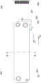
FIG. 6 is a perspective view of a heat exchanger plate according to a second exemplary embodiment of the present invention;
FIG. 7 is a top plan view of the heat exchanger plate shown in FIG. 6;
FIG. 8 is a top plan view of the FIG. 7 illustration of two sections A-A and B-B;
FIG. 9 is a perspective view of a heat exchanger according to the present invention; and
FIG. 10 is a top plan view of the heat exchanger shown in FIG. 9, showing section A-A.
Detailed Description
All figures share a common set of reference numerals, which represent like parts. Further, for the two main exemplary heat exchange plates 100,200 shown in the figures, the respective last two digits in each reference number represent the corresponding portions of the two plates (where applicable).
Thus, fig. 1-5 show a plate 100 for a heat exchanger between a first medium and a second medium. The first medium and the second medium may each, independently of each other, be a liquid or a gas and/or transition from one to the other (using said plates 100 as part of a component in a heat exchanger according to the invention) due to a heat exchange effect taking place between said media.
The panels 100,200 are associated with a main extension plane, not indicated in the figures but lying in the plane of the paper in figures 1, 5, 7 and 8. Furthermore, the plates 100,200 are associated with a main longitudinal direction L and a transverse direction C. The transverse direction C is perpendicular to the main longitudinal direction L and parallel to the main plane.
The plate 100 comprises a first heat transfer surface 101 extending substantially parallel to said main plane and arranged to be in contact with a first medium during heat exchange, which first medium flows substantially in a first flow direction F1 along the first surface 101 during use of the plate 100 in said heat exchanger. Furthermore, the plate 100 comprises a second heat transfer surface 102 extending substantially parallel to said main plane and arranged to be in contact with a second medium flowing along the second surface 102 substantially in a second flow direction F2 during use. Both flow directions F1 and F2 are preferably substantially parallel to the longitudinal direction L.
It is noted that the flow directions F1 and F2 shown in the figures are such that the plate 100 is used for a counter-flow heat exchanger. However, it will be appreciated that the principles described herein are also applicable to co-current heat exchangers, in which case F1 and F2 will be directed in the same direction, or at least in substantially the same direction.
The plate 100 comprises (in reverse order in the longitudinal direction L) a first region 110, a second region 120 and a third region 130. The first zone 110 and the third zone 130 comprise media inlets and outlets, while the second zone 120 is a transfer zone across which media is transported between the zones 110, 130. Preferably, there is no media inlet or outlet along the transfer region 120, which transfer region 120 preferably occupies at least half the total length of the plate 100 in the longitudinal direction L.
Furthermore, the plate 100 comprises an inlet 131 for the first medium and an outlet 112 for the first medium, and an inlet 111 for the second medium and an outlet 132 for the second medium. These inlets 111,131 and outlets 112,132 may be in the form of through holes in the plate 100. In the figure, the through-hole has a circular shape. However, it is to be appreciated that any suitable shape may be used, such as a square shape. Since the plates 100,200 are preferably identical or substantially identical (except for some that are mirror images-see below in relation to the plates 100,200 of the first and second types), when the plates 100,200 are stacked, the through holes will align to form a duct with the same cross-sectional shape as the shape of the through hole in question. During use, when a plate 100 is mounted as one of a plurality of such plates 100 in a heat exchanger according to the invention (as described in further detail below), each of the inlets and outlets 131, 112, 111, 132 is connected to a corresponding inlet/outlet of the other plates in the same plate stack so as to form a general first medium inlet, first medium outlet, second medium inlet and second medium outlet port. The inlet port is then arranged to distribute the first medium and the second medium to the inlet 131;111, respectively, of each plate, and the outlet port is arranged to convey the first medium and the second medium from the outlet 112;132, respectively, and away from the heat exchanger.
The inlet 111 and the outlet 112 are preferably arranged completely in said first region 110, while the inlet 131 and the outlet 132 are preferably arranged completely in the second region 130.
The first and second media flow in flow directions F1, F2 between the respective inlets 111,131 and the respective outlets 112,132 in the channels formed by adjacent plates 100 in the same plate stack, respectively.
More particularly, the heat exchanger according to the invention comprises a plurality of plates 100 of two types (a first type and a second type). The plates 100 of both said first type 100a and said second type 100b are of the type as described herein, wherein the plates of said second type have a shape substantially mirroring the shape of the plates of said first type with respect to said main plane of the plate 100 in question. All of the plates of the first type may be identical within a group of plates of the first type, while all of the plates of the second type may be identical within that group. Furthermore, the plates are arranged in a stack on top of each other (in a direction perpendicular to the main planes of the plates, which main planes are arranged in parallel), wherein the plates of the first and second type are arranged alternately. As the plates of the first and second type are mirror images, corresponding dimples and ridges of the dimples and ridges arranged on adjacent plates are in direct contact with each other and remain in direct contact with each other, so that corresponding first surfaces 101 and/or second surfaces 102 of adjacent plates directly abut each other and so that flow channels 103,104 for said first and second media are formed between said surfaces 101, 102. This is illustrated in fig. 4, which uses plates 100 and is shown with a small distance between each pair of adjacent plates for improved clarity. However, in the installed state, there is no distance — the plates 100 are arranged such that the dimples 123 and ridges 121 of adjacent plates 100 are in direct contact with each other.
It is to be appreciated that the plates 200 (see below) may preferably be stacked in a corresponding manner so as to constitute component parts of a corresponding heat exchanger according to the invention. As is clear from fig. 6, the plate 200 (as opposed to the plate 100) has a curved edge 205 extending around the periphery of the plate 200. The edge 205 is curved with respect to the main plane of the plates 200 and has the purpose of simplifying the process of joining the plates 200 together to form said stack of plates 200. If such a curved edge 205 is present, the edge 205 is not mirrored between the first and second types of panels (as opposed to the ridges and dimples of the panel 200).
In such a heat exchanger, the last plate 100,200 on any end of the stack may be sealed using appropriately designed end plates and form a sealed heat exchanger, with only the inlet/outlet being the inlet and outlet ports described above.
Each plate 100 thus transfers heat between said first medium and a second medium, since the first medium is transported in channels 103 (see fig. 4) and the second medium is transported in channels 104, the channels 103 having first surfaces 101 as limiting side walls and the channels 104 having second surfaces 102 as limiting side walls, the channels 103,104 being separated only by said plates 100. More particularly, the first medium flows in channels defined by the opposite respective surfaces 101 of the adjacent plates 100a,100b, while the second medium (which exchanges heat with the second medium) flows in corresponding channels defined by the opposite respective surfaces 102 of the adjacent plates 100b,100 a. See also fig. 9 and 10.
According to the invention, the first surface 101 comprises protruding ridges 121 defining at least two parallel and open-ended channels 122 extending in the first flow direction F1. Furthermore, the second surface 102 comprises a plurality of protruding dimples 123 arranged in said channels 122 between adjacent respective pairs of said ridges 121.
Herein, "ridge" refers to an elongated protruding geometric feature of the surface 101 in question, the ridge being arranged on this surface 101. Preferably, this ridge 121 in the first surface 101 is associated with a corresponding elongated recess or notch in the opposite surface 102.
Similarly, "dimples" herein refer to the point-like protruding geometric features of the surface 102 in question on which the dimples in question are disposed on the surface 102. Preferably, this dimple is associated with a corresponding punctiform recess or notch in the opposite surface 101. In the figures, the dimples are shown with a generally circular shape. However, it is to be appreciated that any suitable shape may be used, such as square or octagonal, depending on the application. Thus, the word "punctiform" is intended to mean "with a shape, in the main plane of the plate in question, substantially centred with respect to a particular point, rather than elongated".
Both the ridges and the dimples are preferably arranged with a flat top surface arranged to abut a corresponding flat top surface of a corresponding ridge or dimple, respectively, of an adjacently arranged mirrored heat exchanger plate.
The panel 100 is preferably manufactured from sheet metal with a material thickness that is preferably substantially equal across the entire major plane of the panel 100, and in particular across the ridges 121 and dimples 123,113,114,133,134 (see below). Advantageously, the plate 100 is manufactured from a piece of sheet metal which is stamped into the desired shape.
It has been found that a heat exchanger plate 100 with such a pattern of channel-forming ridges 121 and dimples 123 arranged in the formed channels 122 provides very good mechanical stability when used as a component part in a heat exchanger of the type described herein, while still being able to transfer heat between said first and second media very efficiently across a wide variety of applications. The use of such a plate 100 also makes it possible to design the ridges and dimples with a very small height (see below) in order to achieve a heat exchanger using only a very small amount of the first medium and/or the second medium. In particular, the ridge height can be made very small, whereby the amount of the first medium can be reduced. Such miniaturization can be done without compromising efficiency and pressure drop requirements.
6-8 illustrate a second exemplary heat exchanger plate 200 with corresponding first and second surfaces 201 and 202; the regions 210,220, 230; inlets 211, 231; the outlets 212, 232; ridge 221, channel 222, and dimple 223. The second heat exchanger plate 200 provides similar advantages as the first plate 100.
As shown in the figures, the protruding ridges 121,221 preferably define at least three, preferably at least five (in the exemplary plate 100, there are six channels 122, and in the exemplary plate 200, there are seven channels 222) parallel and open-ended channels 122 extending in the first flow direction F1. The inventors have found that for small heat exchangers already significant advantages can be achieved by two (in some cases at least three) such channels, whereas for larger heat exchangers more channels will provide a better distribution of the first medium.
Preferably, the channel 122 extends along substantially the entire second region 120 of the plate 100 in the longitudinal direction L. In particular, at least three of the channels 122 preferably each extend along at least 50%, preferably at least 60%, of the entire length of the plate 100 in the longitudinal direction L.
Preferably, dimples 123 are disposed along at least three of channels 122 (preferably along all channels 122). Preferably, dimples 123 are distributed along substantially the entire length of each individual channel 122, preferably substantially equidistant. Preferably, each channel with dimples 123 is arranged with at least three, preferably at least five, preferably at least ten such dimples 123 along its respective length. The dimples 123 of adjacent parallel channels 122 are preferably arranged such that they are slightly displaced in relation to each other in the longitudinal direction L, as disclosed in the figures.
According to a preferred embodiment, the channels 122 are arranged with the following shape: this shape allows the channel 122,103 (where the channel 103 is formed by two opposing and mirror image open channel portions 122 as described above) to be completely emptied of the first medium when the first medium is in liquid form and when the plate 100 is arranged in the mounted state (which is shown in fig. 5) for use. In this mounted state, the main plane of the plate 100 is oriented substantially vertically with a transverse direction C arranged at an angle a with respect to the vertical V, and a longitudinal direction L inclined at the same angle a with respect to the horizontal direction H. The angle a is preferably between 5 ° and 40 °. In order to completely evacuate said first medium, the curved portion of at least one respective sidewall (in fig. 5, the sidewall facing upwards in the vertical direction) of each of the ridges 121 lacks local minima in the main plane and in said lateral direction C. Since the side walls of the ridge 121 form the floor of the channel 122 when the plate 100 is mounted in the orientation shown in fig. 5, the absence of this local minimum ensures that no liquid first medium will become trapped in such a local minimum during operation, and as a result the channel 122 can be completely emptied. Of course, at the longitudinal end of each ridge 121, the curvature of the ridge sidewall in question is curved downwards, but this is not to be considered as a local minimum in the sense intended here.
It is an important aspect of the present invention that the channel 122 can be completely evacuated when the plate 100 is in a slightly tilted mounting orientation as shown in fig. 5, as it achieves good efficiency for the preferred condensing heat exchanger application described in more full detail below, while still achieving the above-described advantages in terms of efficiency and robustness. Furthermore, problems with overheating in the region where condensate is captured are avoided.
Preferably, at least one of said ridges 121 (preferably at least two adjacent ridges) is interrupted at least one position along said first flow direction F1, defining a respective mixing zone 124 for the first medium flowing through a corresponding adjacent one of said channels 122. Further preferably, said mixing zone 124 interconnects all or at least a majority of said parallel channels 122 present at said at least one position along the first flow direction F1. This provides good heat transfer efficiency while maintaining the structural robustness of the heat exchanger. By distributing the first medium evenly across the transverse direction, the plate 100 tension is also kept to a minimum (since the heat transfer process will be uniform). According to an alternative embodiment, the mixing zone 124 does not interconnect all of said parallel channels 122 present at said at least one position along the first flow direction F1.
In particular, it is preferred that several such mixing zones 124 are arranged at different positions, such as equidistantly, in the longitudinal direction L. It is also preferred that adjacent mixing zones 124 are displaced relative to each other in the transverse direction C, as shown in the figures, such that the at least one channel 122 extends uninterrupted through the at least one mixing zone.
In fig. 1-5, the mixing zones 124 are arranged as simple interruptions in the respective ridges 121, allowing the first medium to mix between the channels 122 at the mixing zone 124 in question. However, as shown in fig. 6-8, it is alternatively preferred that the second surface 102 comprises at least one protruding barrier structure, preferably a ridge 225, extending in a direction substantially perpendicular to the second flow direction F2 and arranged in said mixing zone 224, defining a penetrable barrier for the second medium. Alternatively, the ridge 225 may comprise a connected barrier that is impenetrable to the second medium, but does not extend across the entire lateral direction C, so as to allow the first medium to pass through, but force it to move along a curved path.
As mentioned above, the plate 100 preferably comprises (in reverse order along the main longitudinal direction L) regions 110, 120 and 130. The region 130 may comprise a first media inlet region on the first surface 101. Region 120 may include a first media transfer region on first surface 101. The region 110 may include a first media exit region on the first surface 101.
In a preferred embodiment, the first surface 101 comprises at least three mixing zones 124 of the type described above, which are arranged at different positions in the first flow direction F1, and wherein the mixing zones 124 are arranged more densely or more closely as seen in the first flow direction F1 closer to the first media inlet region 130 than farther from the first media inlet region 130. Note that this varying blend region 124 density is not shown in the figure.
In the preferred case of a first media inlet region, a first media transfer region and a first media outlet region, the plate 100 also preferably includes on its opposite second surface 102 a second media inlet region overlapping the first media outlet region and a second media outlet region overlapping the first media inlet region. This then defines the plates for use in a counter flow heat exchanger. Alternatively, for a parallel flow heat exchanger, the plate 100 may comprise a second medium outlet region on the second surface 102 overlapping the first medium outlet region and a second medium inlet region overlapping the first medium inlet region. For both heat exchanger types, the plate 100 preferably comprises a second medium transfer area on the second surface 102, which overlaps the first medium transfer area.
In particular, it is preferred that the first medium inlet region comprises a first medium inlet 131 and the first medium outlet region comprises a first medium outlet 112. Then, it is preferred that the first medium inlet 131 has a larger (preferably at least twice the size) cross section than the first medium outlet 112 in the main plane, in particular in case the heat exchanger is a condenser type heat exchanger. Thus, in the preferred case (where the inlet 131 and outlet 112 are through holes), the cross-sectional dimension is the hole dimension. This configuration is suitable for an efficient construction when using a first medium that condenses from the gas phase to the liquid phase (due to heat exchange).
Furthermore, it is preferred that the first medium inlet area comprises a pattern of protrusions 235 (see fig. 6 and 7), preferably short ridges extending with the member in the first medium flow direction F1, arranged to distribute the first medium to the respective inlets of at least two of said parallel channels 222.
With respect to the first media outlet region, it is preferred that the region includes at least two (preferably at least three) ridges 115 on the first surface 101 defining at least one (preferably at least two and preferably parallel) channel 116 extending in a direction oblique to the first flow direction F1, as shown in fig. 1-3 and 5. Preferably, the channel 116 extends in a direction that pushes the first medium towards the first medium outlet 112. This provides a very efficient discharge of the heat exchanger (from the condensed first medium in the liquid phase), especially when installed in an inclined orientation, such as the one shown in fig. 5. Preferably, first surface 101 channel 116 includes dimples 117 along second surface 102 of channel 116.
According to a very preferred embodiment, at least one (preferably both) of the first surface 101 and the second surface 102 comprises a respective plurality of additional protruding dimples, in addition to the above described ridges 121,221 and dimples 123,223 arranged in the channels 122, 222. In the figure, these additional dimples are shown as: first surface 101,201 dimples 113,213 in first region 110, 210; the first surface 101,201 dimples 133,233 in the third region 130, 230; the second surface 102,202 dimples 114,214 in the first region 110, 210; and second surface 102,202 dimples 134,234 in third regions 130, 230. Preferably, the panels 100,200 include all four or these types of dimples 113,133,114,134;213,233,214,234.
These dimples share the following common objectives: distributing respective media over respective surfaces 101,102,201,202 of the plates 100, 200; the heat transfer efficiency is improved; as well as providing mechanical stability to the heat exchanger.
In particular, it is preferred that the first surface 101,201 comprises a greater number (preferably at least two, preferably at least three) of said additional dimples 113,133;213,233 compared to the number of additional dimples 114,134;214,234 of the second surface 102, 202. This has proven to achieve a very efficient heat transfer (especially in the case of a condenser-type heat exchanger) without jeopardizing its mechanical stability. Furthermore, this makes it possible to handle greater pressure tolerances of the medium for the heat exchanger.
As is clear from fig. 4, the first media channels 103 are lower (in a direction perpendicular to the main plane of each plate 100) than the second media channels 104. This is particularly preferred in the case of a condenser-type heat exchanger, in which the first medium is condensed as a result of the heat exchange.
In particular, it is preferred that the respective heights of the dimples and ridges described above perpendicular to the main plane define a first flow height for a first medium in the first medium channel 103 and a second flow height for a second medium in the second channel 104. Then, it is preferred that the second flow height is at least 2 times (preferably at least 5 times) the first flow height.
In order for all corresponding dimples and ridges to abut between adjacent mirrored plates, it will be appreciated that all dimples and ridges on any surface 101,102;201,202 preferably have the same height (as measured from the major plane).
In a particularly preferred embodiment, the first flow height of the first media channel 103 is at most 1.5mm, preferably at most 1mm, preferably at least 0.4 mm. This means that the height of the individual dimples and ridges (including any additional material used to join the plates together, such as brazing material between adjacent dimples and ridges) is at most 0.75mm, preferably 0.50mm, preferably at least 0.20 mm. In the preferred case of structures brazed together (see below), it is preferred that the brazing material (preferably in the form of a foil, such as copper foil) used prior to heating is 0.01mm to 0.08mm thick.
As regards the parallel channels 122,222, they are preferably between 5mm and 20mm, preferably between 8mm and 15mm, in the transverse direction C.
According to a highly preferred embodiment, the plates 100,200 together form a heat exchanger by being brazed together in the above-described stacked configuration such that corresponding ones of the dimples and ridges of adjacent mirror image plates 100,200 are brazed together with the top surface facing the top surface. This results in a very robust construction without risking the integrity of the complex channel formed between the ridge and the dimple. In particular, the plates 100,200 are preferably made of stainless steel and are brazed together using copper or nickel; or alternatively, the plates 100,200 may be made of aluminum and brazed together using aluminum. In practice, the plates 100,200 are arranged in the stacked configuration with the brazed foil material therebetween. The entire stack is then heated in a furnace, causing the brazing material to melt and permanently join the plates 100,200 together via the dimples and ridges described above.
In particular, this heat exchanger according to the invention may preferably be a closed counter-flow or co-flow heat exchanger comprising: a first media inlet port 353 arranged to distribute a first media to a respective first media channel 103 in contact with the first surface 101 of the plate 100; a first medium outlet port 351 arranged to direct a first medium from said first channel 103 in contact with said first surface 101 and to direct the first medium out of the heat exchanger; a second media inlet port 350 arranged to distribute a second media to a respective second media channel 104 in contact with the second surface 102 of the plate; and a second medium outlet port 352 arranged to lead a second medium from said second medium channel 104 in contact with the second surface 102 and out of the heat exchanger. With regard to the heat exchanger using the plate 200 as shown in fig. 6-8, the corresponding applies.
In particular, and as mentioned above, the heat exchanger is a condenser type heat exchanger arranged to heat exchange a first medium in a gas phase with a second medium such that the first medium is condensed into liquid form. In this case, it is preferable that the heat exchanger is arranged such that the condensed liquid first medium subsequently flows out from the first medium outlet port 351.
In particular, the present invention can be used in a specific case, wherein the first medium is a refrigerant, preferably a hydrocarbon, preferably propane. Similarly, the second medium may preferably be a liquid, preferably water.
Preferred uses of such heat exchangers include use as heat exchangers in cooling devices (such as freezers or refrigerators); a heat exchanger in a heat pump for heating indoor air, water or the like of a nature; heat exchangers used for industrial heat exchange and refrigeration purposes (such as within the food industry); and so on.
Preferably, the heat exchanger according to the invention has a maximum of 1 meter in its longest dimension.
Fig. 9 and 10 show a heat exchanger 300 comprising a plurality (10 in the example shown) of heat exchange plates 200 of the type described above and shown in fig. 6-8. The plates 200 are stacked one on top of the other with every other plate 200 being a mirror image relative to its adjacent neighboring plates (also as described above). It is noted that in the heat exchanger 300, the curved edge 205 of each plate 200 is not a mirror image.
The first medium enters the heat exchanger 300 via the first medium inlet port 353, the first medium inlet port 353 communicating with all the channels formed between the respective adjacent pairs of plates 200 and delimited by their respective first surfaces 201. Preferably, the channels are parallel such that the first medium flows in co-current flow in the first flow direction F1. The first medium then collects from these channels and exits via first medium outlet port 351.
The second medium enters the heat exchanger 300 via a second medium inlet port 350, the second medium inlet port 350 communicating with all the channels formed between the respective adjacent pairs of plates 200 and delimited by their respective second surfaces 202. Preferably, the channels are parallel such that the second medium flows in co-current flow in the second flow direction F2. The second medium then collects from these channels and exits via the second medium outlet port 352.
It will thus be appreciated that the flow of both the first and second media flows through a plurality of channels of the type described in co-current flow between pairs of individual plates 200 in the stack between respective inlet and outlet ports.
As best seen in fig. 10, the heat exchanger 300 further includes end plates 360,361 for defining the channels on each end of the stack of plates 200, ensuring that the heat exchanger 300 is entirely closed and liquid and gas tight except for ports 350 and 353.
The preferred embodiments have been described above. It will be apparent, however, to one skilled in the art that many modifications can be made to the disclosed embodiments without departing from the basic inventive concepts herein.
In general, the above-described features of the plates 100,200 and the heat exchanger may be freely combined (when applicable).
All that is described with respect to panel 100 is equally relevant to panel 200 and vice versa (where applicable). Thus, for example, the plate 200 may also be arranged with a pattern of inclined ridges 115 as shown in the plate 100, or the like.
The particular pattern of dimples and ridges shown in the figures may vary so long as the above design principles are adhered to.
The invention is therefore not limited to the described embodiments but may be varied within the scope of the appended claims.
Claims (17)
1. Heat exchanger for heat exchange between a first medium and a second medium, comprising a plurality of plates of a first type (100a) and of a second type (100b), said plates being associated with a main extension plane and a main longitudinal direction (L) and comprising:
a first heat transfer surface (101,201) extending substantially parallel to the main extension plane and arranged in contact with the first medium flowing along the first heat transfer surface (101,201) in a first flow direction (F1); and
a second heat transfer surface (102,202) extending substantially parallel to the main extension plane and arranged in contact with the second medium flowing along the second heat transfer surface (102,202) in a second flow direction (F2);
wherein the first heat transfer surface (101,201) comprises protruding ridges (121,221) defining at least two parallel and open-ended channels (122,222) extending in the first flow direction (F1), and wherein the second heat transfer surface (102,202) comprises a plurality of protruding dimples (123,223) arranged in the channels (122,222) between adjacent respective pairs of the ridges (121,221),
wherein the second type of plates (100b) have a shape substantially mirroring the shape of the first type of plates (100a) arranged in a stack on top of each other, wherein the first type of plates (100a) and the second type of plates (100b) are alternately arranged, whereby corresponding ones of the dimples (123,223) and ridges (121,221) of adjacent plates are in direct contact with each other and are kept in direct contact with each other, such that corresponding first heat transfer surfaces (101,201) and/or second heat transfer surfaces (102,202) of adjacent plates abut each other, and such that flow channels (103,104) for the first and second media are formed between the heat transfer surfaces (101,102,201,202),
characterised in that the plates are brazed together such that corresponding ones of the dimples (123,223) and ridges (121,221) of adjacent mirror image plates are brazed together.
2. The heat exchanger according to claim 1, wherein the protruding ridges (121,221) define at least three parallel and open-ended channels (122,222) extending in the first flow direction (F1).
3. The heat exchanger according to claim 1 or 2, wherein the plates are associated with a transverse direction (C) perpendicular to the main longitudinal direction (L) and parallel to the main extension plane, and wherein the curved portion of at least one respective side wall of each of the ridges (121,221) lacks local minima in the main extension plane and in the transverse direction (C).
4. The heat exchanger according to claim 1 or 2, wherein at least one of the ridges (121,221) is interrupted at least one position in the first flow direction (F1), defining a respective mixing zone (124,224) for the first medium flowing through a corresponding adjacent one of the channels (122, 222).
5. The heat exchanger according to claim 4, characterized in that at least two adjacent ones of the ridges (121,221) are interrupted at least one position in the first flow direction (F1).
6. The heat exchanger according to claim 4, wherein the mixing zone (124,224) interconnects a majority of the parallel channels (122,222) present at the at least one location along the first flow direction (F1).
7. A heat exchanger according to claim 4, characterised in that the second heat transfer surface comprises at least one protruding barrier structure (225) extending in a direction substantially perpendicular to the second flow direction (F2) and arranged in the mixing zone, defining a penetrable barrier for the second medium.
8. The heat exchanger according to claim 7, wherein the protruding barrier structure (225) is a protruding ridge.
9. A heat exchanger according to claim 1 or 2, wherein the plate comprises, in order in the main longitudinal direction (L), a first medium inlet region, a first medium transfer region and a first medium outlet region, and wherein the channels (122,222) are arranged in the first medium transfer region.
10. The heat exchanger of claim 9, wherein the plate further comprises:
a second media inlet region overlapping the first media outlet region on an opposite heat transfer surface of the plate and a second media outlet region overlapping the first media inlet region on an opposite heat transfer surface of the plate; or
A second media outlet region overlapping the first media outlet region on an opposite heat transfer surface of the plate and a second media inlet region overlapping the first media inlet region on an opposite heat transfer surface of the plate; and
a second media transfer region on an opposite heat transfer surface of the plate overlapping the first media transfer region.
11. A heat exchanger according to claim 9, wherein the first medium inlet region comprises a pattern of protrusions (235) arranged to distribute the first medium to respective inlets of at least two of the parallel channels.
12. Heat exchanger according to claim 1 or 2, wherein said first flow direction (F1) is substantially parallel to said main longitudinal direction (L).
13. Heat exchanger according to claim 12, wherein said second flow direction (F2) is substantially parallel to said main longitudinal direction (L).
14. A heat exchanger according to claim 1 or claim 2, wherein both the first heat transfer surface (101,201) and the second heat transfer surface (102,202) comprise a respective plurality of additional protruding dimples (113,114,133,134,213,214,233,234) in addition to the dimples (123,223) arranged in the channels (122, 222).
15. The heat exchanger according to claim 1 or claim 2, wherein respective heights of the dimples (123,223) and ridges (121,221) perpendicular to the main extension plane define a first flow height for the first medium and a second flow height for the second medium, and wherein the second flow height is at least 2 times the first flow height.
16. The heat exchanger of claim 15, wherein the second flow height is at least 5 times the first flow height.
17. The heat exchanger of claim 1 or claim 2, wherein the heat exchanger is a closed counter-flow or co-flow heat exchanger comprising:
a first media inlet port (353) arranged to distribute the first media to the respective first heat transfer surfaces (101,201) of the plates;
a first medium outlet port (351) arranged to direct the first medium from the first heat transfer surface (101,201) and to direct the first medium out of the heat exchanger;
a second media inlet port (350) arranged to distribute the second media to a respective second heat transfer surface (102,202) of the plate; and
a second medium outlet port (352) arranged to direct the second medium from the second heat transfer surface (102,202) and to direct the second medium out of the heat exchanger.
Applications Claiming Priority (3)
| Application Number | Priority Date | Filing Date | Title |
|---|---|---|---|
| EP16192854.4A EP3306253B1 (en) | 2016-10-07 | 2016-10-07 | Heat exchanging plate and heat exchanger |
| EP16192854.4 | 2016-10-07 | ||
| PCT/EP2017/053537 WO2018065124A1 (en) | 2016-10-07 | 2017-02-16 | Heat exchanging plate and heat exchanger |
Publications (2)
| Publication Number | Publication Date |
|---|---|
| CN109863360A CN109863360A (en) | 2019-06-07 |
| CN109863360B true CN109863360B (en) | 2021-09-14 |
Family
ID=57113201
Family Applications (1)
| Application Number | Title | Priority Date | Filing Date |
|---|---|---|---|
| CN201780061880.5A Active CN109863360B (en) | 2016-10-07 | 2017-02-16 | Heat exchanger |
Country Status (12)
| Country | Link |
|---|---|
| US (1) | US20190226771A1 (en) |
| EP (2) | EP3306253B1 (en) |
| JP (1) | JP6871365B2 (en) |
| KR (2) | KR102439518B1 (en) |
| CN (1) | CN109863360B (en) |
| CA (2) | CA3109488C (en) |
| DK (2) | DK3306253T3 (en) |
| ES (2) | ES2733574T3 (en) |
| PL (2) | PL3306253T3 (en) |
| PT (2) | PT3306253T (en) |
| SI (2) | SI3306253T1 (en) |
| WO (1) | WO2018065124A1 (en) |
Families Citing this family (9)
| Publication number | Priority date | Publication date | Assignee | Title |
|---|---|---|---|---|
| ES2738774T3 (en) | 2017-01-19 | 2020-01-27 | Alfa Laval Corp Ab | Heat exchange plate and heat exchanger |
| CN108645268A (en) * | 2018-04-30 | 2018-10-12 | 南京理工大学 | Add the plate-type heat exchanger slab of semicolumn protrusion |
| CN108801035A (en) * | 2018-04-30 | 2018-11-13 | 南京理工大学 | Novel fishbone adds the plate-type heat exchanger slab of semi-cylindrical protrusion |
| CN108645267A (en) * | 2018-04-30 | 2018-10-12 | 南京理工大学 | Novel fishbone adds the plate-type heat exchanger slab of fusiformis protrusion |
| CN108827058A (en) * | 2018-04-30 | 2018-11-16 | 南京理工大学 | A kind of plus shuttle shape protrusion plate-type heat exchanger slab |
| CN109442806B (en) * | 2018-09-03 | 2020-11-10 | 广东工业大学 | Liquid-separation phase-change plate heat exchanger and application thereof |
| CN111322888A (en) * | 2018-12-13 | 2020-06-23 | 浙江盾安热工科技有限公司 | Heat exchanger and air conditioner with same |
| FR3096446B1 (en) * | 2019-05-20 | 2021-05-21 | Valeo Systemes Thermiques | PLATE OF A HEAT EXCHANGER FOR VEHICLE |
| DE102019008914A1 (en) * | 2019-12-20 | 2021-06-24 | Stiebel Eltron Gmbh & Co. Kg | Heat pump with optimized refrigerant circuit |
Citations (2)
| Publication number | Priority date | Publication date | Assignee | Title |
|---|---|---|---|---|
| CN202092498U (en) * | 2011-05-11 | 2011-12-28 | 天通浙江精电科技有限公司 | Heat exchanger with streamline integral strengthening heat exchanging plates |
| CN105953621A (en) * | 2015-04-29 | 2016-09-21 | 于仁麟 | Plate heat exchanger with changeable runner width |
Family Cites Families (22)
| Publication number | Priority date | Publication date | Assignee | Title |
|---|---|---|---|---|
| US2526157A (en) * | 1941-08-07 | 1950-10-17 | Ramen Torsten | Apparatus for heat exchange between liquids |
| JPS5276508A (en) * | 1975-12-19 | 1977-06-28 | Hisaka Works Ltd | Condenser |
| US4210127A (en) * | 1978-06-22 | 1980-07-01 | Olin Corporation | Heat exchanger panel having reference indicia and improved flow distribution |
| FR2575279B1 (en) * | 1984-12-21 | 1989-07-07 | Barriquand | PLATE HEAT EXCHANGER |
| SE502254C2 (en) * | 1990-12-17 | 1995-09-25 | Alfa Laval Thermal Ab | Plate heat exchanger and method for producing a plate heat exchanger |
| JP3212350B2 (en) * | 1992-03-30 | 2001-09-25 | 株式会社日阪製作所 | Plate heat exchanger |
| IT1263611B (en) * | 1993-02-19 | 1996-08-27 | Giannoni Srl | PLATE HEAT EXCHANGER |
| JPH08101000A (en) * | 1994-09-30 | 1996-04-16 | Hisaka Works Ltd | Plate-type heat exchanger |
| US6401804B1 (en) * | 1999-01-14 | 2002-06-11 | Denso Corporation | Heat exchanger only using plural plates |
| DE19948222C2 (en) | 1999-10-07 | 2002-11-07 | Xcellsis Gmbh | Plate heat exchanger |
| JP2002018512A (en) * | 2000-07-04 | 2002-01-22 | Yano Engineering:Kk | Metal hollow shape and method of manufacturing it |
| AU5591301A (en) * | 2000-08-08 | 2002-02-14 | Modine Manufacturing Company | Method of making a tube for a heat exchanger |
| JP3965901B2 (en) * | 2000-10-27 | 2007-08-29 | 株式会社デンソー | Evaporator |
| JP2005121319A (en) * | 2003-10-17 | 2005-05-12 | Toho Gas Co Ltd | Heat exchanger |
| DK1630510T3 (en) | 2004-08-28 | 2007-04-23 | Swep Int Ab | Plate heat exchanger |
| US7264045B2 (en) * | 2005-08-23 | 2007-09-04 | Delphi Technologies, Inc. | Plate-type evaporator to suppress noise and maintain thermal performance |
| JP4756585B2 (en) * | 2005-09-09 | 2011-08-24 | 臼井国際産業株式会社 | Heat exchanger tube for heat exchanger |
| DE202007007169U1 (en) * | 2007-05-16 | 2008-09-25 | Akg-Thermotechnik Gmbh & Co. Kg | Heat exchanger for gaseous media |
| US9033026B2 (en) | 2008-03-13 | 2015-05-19 | Danfoss A/S | Double plate heat exchanger |
| JP5629558B2 (en) * | 2010-11-15 | 2014-11-19 | トヨタ自動車株式会社 | Vehicle heat exchanger |
| CA3083317C (en) * | 2012-09-20 | 2021-02-09 | Airia Leasing Inc. | Planar plate core and method of assembly |
| JP6333973B2 (en) * | 2013-10-14 | 2018-05-30 | アイレック アーベー | Heat exchanger plate and heat exchanger |
-
2016
- 2016-10-07 EP EP16192854.4A patent/EP3306253B1/en active Active
- 2016-10-07 PL PL16192854T patent/PL3306253T3/en unknown
- 2016-10-07 DK DK16192854.4T patent/DK3306253T3/en active
- 2016-10-07 PT PT16192854T patent/PT3306253T/en unknown
- 2016-10-07 SI SI201630253T patent/SI3306253T1/en unknown
- 2016-10-07 ES ES16192854T patent/ES2733574T3/en active Active
-
2017
- 2017-02-16 PL PL17706195T patent/PL3523591T3/en unknown
- 2017-02-16 KR KR1020217008003A patent/KR102439518B1/en active IP Right Grant
- 2017-02-16 DK DK17706195.9T patent/DK3523591T3/en active
- 2017-02-16 CN CN201780061880.5A patent/CN109863360B/en active Active
- 2017-02-16 SI SI201730619T patent/SI3523591T1/en unknown
- 2017-02-16 KR KR1020197012499A patent/KR102231142B1/en active IP Right Grant
- 2017-02-16 CA CA3109488A patent/CA3109488C/en active Active
- 2017-02-16 US US16/337,008 patent/US20190226771A1/en active Pending
- 2017-02-16 PT PT177061959T patent/PT3523591T/en unknown
- 2017-02-16 ES ES17706195T patent/ES2853203T3/en active Active
- 2017-02-16 JP JP2019518403A patent/JP6871365B2/en active Active
- 2017-02-16 EP EP17706195.9A patent/EP3523591B1/en active Active
- 2017-02-16 WO PCT/EP2017/053537 patent/WO2018065124A1/en active Search and Examination
- 2017-02-16 CA CA3039275A patent/CA3039275C/en active Active
Patent Citations (2)
| Publication number | Priority date | Publication date | Assignee | Title |
|---|---|---|---|---|
| CN202092498U (en) * | 2011-05-11 | 2011-12-28 | 天通浙江精电科技有限公司 | Heat exchanger with streamline integral strengthening heat exchanging plates |
| CN105953621A (en) * | 2015-04-29 | 2016-09-21 | 于仁麟 | Plate heat exchanger with changeable runner width |
Also Published As
| Publication number | Publication date |
|---|---|
| EP3523591B1 (en) | 2020-12-16 |
| PT3523591T (en) | 2021-02-16 |
| KR102231142B1 (en) | 2021-03-24 |
| ES2733574T3 (en) | 2019-12-02 |
| EP3306253B1 (en) | 2019-04-10 |
| JP6871365B2 (en) | 2021-05-12 |
| ES2853203T3 (en) | 2021-09-15 |
| JP2019530845A (en) | 2019-10-24 |
| EP3523591A1 (en) | 2019-08-14 |
| CA3109488A1 (en) | 2018-04-12 |
| SI3523591T1 (en) | 2021-04-30 |
| KR20190065338A (en) | 2019-06-11 |
| EP3306253A1 (en) | 2018-04-11 |
| US20190226771A1 (en) | 2019-07-25 |
| DK3306253T3 (en) | 2019-07-22 |
| KR102439518B1 (en) | 2022-09-05 |
| PT3306253T (en) | 2019-07-12 |
| CA3039275A1 (en) | 2018-04-12 |
| CA3109488C (en) | 2021-06-08 |
| PL3306253T3 (en) | 2019-08-30 |
| SI3306253T1 (en) | 2019-08-30 |
| WO2018065124A1 (en) | 2018-04-12 |
| PL3523591T3 (en) | 2021-05-04 |
| CN109863360A (en) | 2019-06-07 |
| DK3523591T3 (en) | 2021-02-22 |
| CA3039275C (en) | 2021-06-15 |
| KR20210033070A (en) | 2021-03-25 |
Similar Documents
| Publication | Publication Date | Title |
|---|---|---|
| CN109863360B (en) | Heat exchanger | |
| CN110268216B (en) | Heat exchange plate and heat exchanger | |
| US11105561B2 (en) | Heat exchanger plate and heat exchanger | |
| JP4874365B2 (en) | Plate heat exchanger and refrigeration cycle apparatus using the heat exchanger | |
| US11898805B2 (en) | Heat exchanger plate and heat exchanger | |
| EP3447428A1 (en) | Heat exchanger plate and heat exchanger | |
| US11105560B2 (en) | Heat exchanger |
Legal Events
| Date | Code | Title | Description |
|---|---|---|---|
| PB01 | Publication | ||
| PB01 | Publication | ||
| SE01 | Entry into force of request for substantive examination | ||
| SE01 | Entry into force of request for substantive examination | ||
| GR01 | Patent grant | ||
| GR01 | Patent grant |