CN109843358B - Drug delivery device with end of injection indication mechanism - Google Patents
Drug delivery device with end of injection indication mechanism Download PDFInfo
- Publication number
- CN109843358B CN109843358B CN201780011134.5A CN201780011134A CN109843358B CN 109843358 B CN109843358 B CN 109843358B CN 201780011134 A CN201780011134 A CN 201780011134A CN 109843358 B CN109843358 B CN 109843358B
- Authority
- CN
- China
- Prior art keywords
- plunger rod
- drive mechanism
- rotor
- needle cover
- delivery device
- Prior art date
- Legal status (The legal status is an assumption and is not a legal conclusion. Google has not performed a legal analysis and makes no representation as to the accuracy of the status listed.)
- Active
Links
Images


Classifications
-
- A—HUMAN NECESSITIES
- A61—MEDICAL OR VETERINARY SCIENCE; HYGIENE
- A61M—DEVICES FOR INTRODUCING MEDIA INTO, OR ONTO, THE BODY; DEVICES FOR TRANSDUCING BODY MEDIA OR FOR TAKING MEDIA FROM THE BODY; DEVICES FOR PRODUCING OR ENDING SLEEP OR STUPOR
- A61M5/00—Devices for bringing media into the body in a subcutaneous, intra-vascular or intramuscular way; Accessories therefor, e.g. filling or cleaning devices, arm-rests
- A61M5/178—Syringes
- A61M5/31—Details
- A61M5/315—Pistons; Piston-rods; Guiding, blocking or restricting the movement of the rod or piston; Appliances on the rod for facilitating dosing ; Dosing mechanisms
- A61M5/31565—Administration mechanisms, i.e. constructional features, modes of administering a dose
- A61M5/31576—Constructional features or modes of drive mechanisms for piston rods
- A61M5/31583—Constructional features or modes of drive mechanisms for piston rods based on rotational translation, i.e. movement of piston rod is caused by relative rotation between the user activated actuator and the piston rod
- A61M5/31585—Constructional features or modes of drive mechanisms for piston rods based on rotational translation, i.e. movement of piston rod is caused by relative rotation between the user activated actuator and the piston rod performed by axially moving actuator, e.g. an injection button
-
- A—HUMAN NECESSITIES
- A61—MEDICAL OR VETERINARY SCIENCE; HYGIENE
- A61M—DEVICES FOR INTRODUCING MEDIA INTO, OR ONTO, THE BODY; DEVICES FOR TRANSDUCING BODY MEDIA OR FOR TAKING MEDIA FROM THE BODY; DEVICES FOR PRODUCING OR ENDING SLEEP OR STUPOR
- A61M5/00—Devices for bringing media into the body in a subcutaneous, intra-vascular or intramuscular way; Accessories therefor, e.g. filling or cleaning devices, arm-rests
- A61M5/178—Syringes
- A61M5/31—Details
- A61M5/315—Pistons; Piston-rods; Guiding, blocking or restricting the movement of the rod or piston; Appliances on the rod for facilitating dosing ; Dosing mechanisms
- A61M5/31565—Administration mechanisms, i.e. constructional features, modes of administering a dose
- A61M5/31576—Constructional features or modes of drive mechanisms for piston rods
- A61M5/31578—Constructional features or modes of drive mechanisms for piston rods based on axial translation, i.e. components directly operatively associated and axially moved with plunger rod
- A61M5/31581—Constructional features or modes of drive mechanisms for piston rods based on axial translation, i.e. components directly operatively associated and axially moved with plunger rod performed by rotationally moving or pivoting actuator operated by user, e.g. an injection lever or handle
-
- A—HUMAN NECESSITIES
- A61—MEDICAL OR VETERINARY SCIENCE; HYGIENE
- A61M—DEVICES FOR INTRODUCING MEDIA INTO, OR ONTO, THE BODY; DEVICES FOR TRANSDUCING BODY MEDIA OR FOR TAKING MEDIA FROM THE BODY; DEVICES FOR PRODUCING OR ENDING SLEEP OR STUPOR
- A61M5/00—Devices for bringing media into the body in a subcutaneous, intra-vascular or intramuscular way; Accessories therefor, e.g. filling or cleaning devices, arm-rests
- A61M5/178—Syringes
- A61M5/20—Automatic syringes, e.g. with automatically actuated piston rod, with automatic needle injection, filling automatically
- A61M5/2033—Spring-loaded one-shot injectors with or without automatic needle insertion
-
- A—HUMAN NECESSITIES
- A61—MEDICAL OR VETERINARY SCIENCE; HYGIENE
- A61M—DEVICES FOR INTRODUCING MEDIA INTO, OR ONTO, THE BODY; DEVICES FOR TRANSDUCING BODY MEDIA OR FOR TAKING MEDIA FROM THE BODY; DEVICES FOR PRODUCING OR ENDING SLEEP OR STUPOR
- A61M5/00—Devices for bringing media into the body in a subcutaneous, intra-vascular or intramuscular way; Accessories therefor, e.g. filling or cleaning devices, arm-rests
- A61M5/178—Syringes
- A61M5/31—Details
- A61M5/315—Pistons; Piston-rods; Guiding, blocking or restricting the movement of the rod or piston; Appliances on the rod for facilitating dosing ; Dosing mechanisms
- A61M5/31511—Piston or piston-rod constructions, e.g. connection of piston with piston-rod
- A61M5/31515—Connection of piston with piston rod
-
- A—HUMAN NECESSITIES
- A61—MEDICAL OR VETERINARY SCIENCE; HYGIENE
- A61M—DEVICES FOR INTRODUCING MEDIA INTO, OR ONTO, THE BODY; DEVICES FOR TRANSDUCING BODY MEDIA OR FOR TAKING MEDIA FROM THE BODY; DEVICES FOR PRODUCING OR ENDING SLEEP OR STUPOR
- A61M5/00—Devices for bringing media into the body in a subcutaneous, intra-vascular or intramuscular way; Accessories therefor, e.g. filling or cleaning devices, arm-rests
- A61M5/178—Syringes
- A61M5/31—Details
- A61M5/315—Pistons; Piston-rods; Guiding, blocking or restricting the movement of the rod or piston; Appliances on the rod for facilitating dosing ; Dosing mechanisms
- A61M5/31525—Dosing
- A61M5/31528—Dosing by means of rotational movements, e.g. screw-thread mechanisms
-
- A—HUMAN NECESSITIES
- A61—MEDICAL OR VETERINARY SCIENCE; HYGIENE
- A61M—DEVICES FOR INTRODUCING MEDIA INTO, OR ONTO, THE BODY; DEVICES FOR TRANSDUCING BODY MEDIA OR FOR TAKING MEDIA FROM THE BODY; DEVICES FOR PRODUCING OR ENDING SLEEP OR STUPOR
- A61M5/00—Devices for bringing media into the body in a subcutaneous, intra-vascular or intramuscular way; Accessories therefor, e.g. filling or cleaning devices, arm-rests
- A61M5/178—Syringes
- A61M5/31—Details
- A61M5/315—Pistons; Piston-rods; Guiding, blocking or restricting the movement of the rod or piston; Appliances on the rod for facilitating dosing ; Dosing mechanisms
- A61M5/31565—Administration mechanisms, i.e. constructional features, modes of administering a dose
- A61M5/31566—Means improving security or handling thereof
- A61M5/3157—Means providing feedback signals when administration is completed
-
- A—HUMAN NECESSITIES
- A61—MEDICAL OR VETERINARY SCIENCE; HYGIENE
- A61M—DEVICES FOR INTRODUCING MEDIA INTO, OR ONTO, THE BODY; DEVICES FOR TRANSDUCING BODY MEDIA OR FOR TAKING MEDIA FROM THE BODY; DEVICES FOR PRODUCING OR ENDING SLEEP OR STUPOR
- A61M5/00—Devices for bringing media into the body in a subcutaneous, intra-vascular or intramuscular way; Accessories therefor, e.g. filling or cleaning devices, arm-rests
- A61M5/178—Syringes
- A61M5/31—Details
- A61M5/32—Needles; Details of needles pertaining to their connection with syringe or hub; Accessories for bringing the needle into, or holding the needle on, the body; Devices for protection of needles
- A61M5/3202—Devices for protection of the needle before use, e.g. caps
- A61M5/3204—Needle cap remover, i.e. devices to dislodge protection cover from needle or needle hub, e.g. deshielding devices
-
- A—HUMAN NECESSITIES
- A61—MEDICAL OR VETERINARY SCIENCE; HYGIENE
- A61M—DEVICES FOR INTRODUCING MEDIA INTO, OR ONTO, THE BODY; DEVICES FOR TRANSDUCING BODY MEDIA OR FOR TAKING MEDIA FROM THE BODY; DEVICES FOR PRODUCING OR ENDING SLEEP OR STUPOR
- A61M5/00—Devices for bringing media into the body in a subcutaneous, intra-vascular or intramuscular way; Accessories therefor, e.g. filling or cleaning devices, arm-rests
- A61M5/178—Syringes
- A61M5/31—Details
- A61M5/32—Needles; Details of needles pertaining to their connection with syringe or hub; Accessories for bringing the needle into, or holding the needle on, the body; Devices for protection of needles
- A61M5/3205—Apparatus for removing or disposing of used needles or syringes, e.g. containers; Means for protection against accidental injuries from used needles
- A61M5/321—Means for protection against accidental injuries by used needles
- A61M5/3243—Means for protection against accidental injuries by used needles being axially-extensible, e.g. protective sleeves coaxially slidable on the syringe barrel
- A61M5/3271—Means for protection against accidental injuries by used needles being axially-extensible, e.g. protective sleeves coaxially slidable on the syringe barrel with guiding tracks for controlled sliding of needle protective sleeve from needle exposing to needle covering position
- A61M5/3272—Means for protection against accidental injuries by used needles being axially-extensible, e.g. protective sleeves coaxially slidable on the syringe barrel with guiding tracks for controlled sliding of needle protective sleeve from needle exposing to needle covering position having projections following labyrinth paths
-
- A—HUMAN NECESSITIES
- A61—MEDICAL OR VETERINARY SCIENCE; HYGIENE
- A61M—DEVICES FOR INTRODUCING MEDIA INTO, OR ONTO, THE BODY; DEVICES FOR TRANSDUCING BODY MEDIA OR FOR TAKING MEDIA FROM THE BODY; DEVICES FOR PRODUCING OR ENDING SLEEP OR STUPOR
- A61M5/00—Devices for bringing media into the body in a subcutaneous, intra-vascular or intramuscular way; Accessories therefor, e.g. filling or cleaning devices, arm-rests
- A61M5/178—Syringes
- A61M5/20—Automatic syringes, e.g. with automatically actuated piston rod, with automatic needle injection, filling automatically
- A61M2005/2006—Having specific accessories
- A61M2005/2013—Having specific accessories triggering of discharging means by contact of injector with patient body
-
- A—HUMAN NECESSITIES
- A61—MEDICAL OR VETERINARY SCIENCE; HYGIENE
- A61M—DEVICES FOR INTRODUCING MEDIA INTO, OR ONTO, THE BODY; DEVICES FOR TRANSDUCING BODY MEDIA OR FOR TAKING MEDIA FROM THE BODY; DEVICES FOR PRODUCING OR ENDING SLEEP OR STUPOR
- A61M5/00—Devices for bringing media into the body in a subcutaneous, intra-vascular or intramuscular way; Accessories therefor, e.g. filling or cleaning devices, arm-rests
- A61M5/178—Syringes
- A61M5/20—Automatic syringes, e.g. with automatically actuated piston rod, with automatic needle injection, filling automatically
- A61M2005/2073—Automatic syringes, e.g. with automatically actuated piston rod, with automatic needle injection, filling automatically preventing premature release, e.g. by making use of a safety lock
- A61M2005/208—Release is possible only when device is pushed against the skin, e.g. using a trigger which is blocked or inactive when the device is not pushed against the skin
-
- A—HUMAN NECESSITIES
- A61—MEDICAL OR VETERINARY SCIENCE; HYGIENE
- A61M—DEVICES FOR INTRODUCING MEDIA INTO, OR ONTO, THE BODY; DEVICES FOR TRANSDUCING BODY MEDIA OR FOR TAKING MEDIA FROM THE BODY; DEVICES FOR PRODUCING OR ENDING SLEEP OR STUPOR
- A61M5/00—Devices for bringing media into the body in a subcutaneous, intra-vascular or intramuscular way; Accessories therefor, e.g. filling or cleaning devices, arm-rests
- A61M5/178—Syringes
- A61M5/31—Details
- A61M5/32—Needles; Details of needles pertaining to their connection with syringe or hub; Accessories for bringing the needle into, or holding the needle on, the body; Devices for protection of needles
- A61M5/3205—Apparatus for removing or disposing of used needles or syringes, e.g. containers; Means for protection against accidental injuries from used needles
- A61M5/321—Means for protection against accidental injuries by used needles
- A61M5/3243—Means for protection against accidental injuries by used needles being axially-extensible, e.g. protective sleeves coaxially slidable on the syringe barrel
- A61M5/3245—Constructional features thereof, e.g. to improve manipulation or functioning
- A61M2005/3247—Means to impede repositioning of protection sleeve from needle covering to needle uncovering position
-
- A—HUMAN NECESSITIES
- A61—MEDICAL OR VETERINARY SCIENCE; HYGIENE
- A61M—DEVICES FOR INTRODUCING MEDIA INTO, OR ONTO, THE BODY; DEVICES FOR TRANSDUCING BODY MEDIA OR FOR TAKING MEDIA FROM THE BODY; DEVICES FOR PRODUCING OR ENDING SLEEP OR STUPOR
- A61M5/00—Devices for bringing media into the body in a subcutaneous, intra-vascular or intramuscular way; Accessories therefor, e.g. filling or cleaning devices, arm-rests
- A61M5/178—Syringes
- A61M5/31—Details
- A61M5/32—Needles; Details of needles pertaining to their connection with syringe or hub; Accessories for bringing the needle into, or holding the needle on, the body; Devices for protection of needles
- A61M5/3205—Apparatus for removing or disposing of used needles or syringes, e.g. containers; Means for protection against accidental injuries from used needles
- A61M5/321—Means for protection against accidental injuries by used needles
- A61M5/3243—Means for protection against accidental injuries by used needles being axially-extensible, e.g. protective sleeves coaxially slidable on the syringe barrel
- A61M5/326—Fully automatic sleeve extension, i.e. in which triggering of the sleeve does not require a deliberate action by the user
- A61M2005/3267—Biased sleeves where the needle is uncovered by insertion of the needle into a patient's body
-
- A—HUMAN NECESSITIES
- A61—MEDICAL OR VETERINARY SCIENCE; HYGIENE
- A61M—DEVICES FOR INTRODUCING MEDIA INTO, OR ONTO, THE BODY; DEVICES FOR TRANSDUCING BODY MEDIA OR FOR TAKING MEDIA FROM THE BODY; DEVICES FOR PRODUCING OR ENDING SLEEP OR STUPOR
- A61M2205/00—General characteristics of the apparatus
- A61M2205/58—Means for facilitating use, e.g. by people with impaired vision
- A61M2205/581—Means for facilitating use, e.g. by people with impaired vision by audible feedback
-
- A—HUMAN NECESSITIES
- A61—MEDICAL OR VETERINARY SCIENCE; HYGIENE
- A61M—DEVICES FOR INTRODUCING MEDIA INTO, OR ONTO, THE BODY; DEVICES FOR TRANSDUCING BODY MEDIA OR FOR TAKING MEDIA FROM THE BODY; DEVICES FOR PRODUCING OR ENDING SLEEP OR STUPOR
- A61M2205/00—General characteristics of the apparatus
- A61M2205/58—Means for facilitating use, e.g. by people with impaired vision
- A61M2205/582—Means for facilitating use, e.g. by people with impaired vision by tactile feedback
-
- A—HUMAN NECESSITIES
- A61—MEDICAL OR VETERINARY SCIENCE; HYGIENE
- A61M—DEVICES FOR INTRODUCING MEDIA INTO, OR ONTO, THE BODY; DEVICES FOR TRANSDUCING BODY MEDIA OR FOR TAKING MEDIA FROM THE BODY; DEVICES FOR PRODUCING OR ENDING SLEEP OR STUPOR
- A61M2205/00—General characteristics of the apparatus
- A61M2205/58—Means for facilitating use, e.g. by people with impaired vision
- A61M2205/583—Means for facilitating use, e.g. by people with impaired vision by visual feedback
Landscapes
- Health & Medical Sciences (AREA)
- Engineering & Computer Science (AREA)
- Heart & Thoracic Surgery (AREA)
- Vascular Medicine (AREA)
- Anesthesiology (AREA)
- Biomedical Technology (AREA)
- Hematology (AREA)
- Life Sciences & Earth Sciences (AREA)
- Animal Behavior & Ethology (AREA)
- General Health & Medical Sciences (AREA)
- Public Health (AREA)
- Veterinary Medicine (AREA)
- Environmental & Geological Engineering (AREA)
- Infusion, Injection, And Reservoir Apparatuses (AREA)
Abstract
A drive mechanism for a conveyor, the drive mechanism comprising: a rotor including an outer surface and an inner surface, the rotor configured to rotate from a first position to a second position; a needle cover including an inner surface that engages the outer surface of the rotor. An end of injection means is arranged at least partly inside the plunger rod spring, the end of injection indicating means providing a signal to a user of the drive mechanism that the injection has been completed.
Description
Technical Field
The present invention relates to a delivery device, and in particular to an improved, easy to use medicament delivery device which provides an audible, tactile and/or visual signal or confirmation to the user when the injection is completed.
Background
Many self-administration drug delivery devices have been developed, i.e. the user himself delivers the drug. There is a need for a medicament delivery device that is safe to use and easy to operate. To meet these requirements, the risk of human error must be minimized, the number of actions to be taken to receive the medicament must be reduced, and the device must be intuitive, easy to use, and ergonomic.
Accordingly, there is a need for a cost effective method and delivery device that minimizes the risk of human error, and it is desirable to have a delivery device that reduces the number of actions that need to be performed in order to receive a medicament. There is also a need for a delivery device that can provide confirmation that the delivery device injection has been completed.
Disclosure of Invention
According to one exemplary embodiment, a drive mechanism for a conveyor is disclosed. The drive mechanism includes: the needle cover includes a rotor including an outer surface and an inner surface and configured to rotate from a first position to a second position, and a needle cover including an inner surface that engages the outer surface of the rotor. The drive mechanism further comprises a plunger rod spring arranged within a cavity defined by the rotor. An end of injection indication means is arranged at least partly within the plunger rod spring, which end of injection indication means provides a signal to a user of the drive mechanism that the injection has been completed.
These and other advantages of the various aspects of the present patent application will be more clearly understood by those skilled in the art from a reading of the following detailed description, with appropriate reference to the accompanying drawings.
Drawings
The novel features believed characteristic of the illustrative embodiments are set forth in the appended claims. The exemplary embodiments and the preferred mode of use, however, as well as a further structure and description thereof, will best be understood by reference to the following detailed description of an exemplary embodiment of the present disclosure when read in conjunction with the accompanying drawings, wherein:
FIG. 1 is a schematic view of a delivery device;
FIG. 2 is a schematic view of various components that make up the drive mechanism of the transport apparatus shown in FIG. 1;
FIG. 3A is a schematic view of the housing shown in FIG. 2;
FIG. 3B is another schematic view of the housing shown in FIG. 3A;
FIG. 4 is a schematic view of the needle shield shown in FIG. 2;
FIG. 5A is a schematic view of the plunger rod shown in FIG. 2;
FIG. 5B is another schematic view of the plunger rod shown in FIG. 5A;
FIG. 6A is a schematic view of the rotor shown in FIG. 2;
FIG. 6B is another schematic view of the rotor shown in FIG. 6A;
FIG. 7A is a schematic view of the cartridge housing shown in FIG. 2;
FIG. 7B is another schematic view of the cartridge housing shown in FIG. 7A;
FIG. 8 is a schematic view of the guide bar shown in FIG. 2;
FIG. 9 is a schematic view of the drive mechanism of the delivery device shown in FIG. 1 with a cover attached;
FIG. 10 is another schematic view of the drive mechanism shown in FIG. 9;
FIG. 11 is a schematic view of the drive mechanism shown in FIG. 9 with the cover removed;
FIG. 12 is another schematic view of the drive mechanism shown in FIG. 11 with the cover removed;
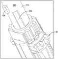
FIG. 13 is a schematic view of the proximal end of the drive mechanism shown in FIG. 10;
FIG. 14 is a schematic view of the drive mechanism shown in FIG. 11 during proximal movement of the needle cover;
fig. 15 is a schematic view of the proximal end of the medicament delivery device shown in fig. 9 after injection;
fig. 16A is a schematic view of the proximal end of the medicament delivery device shown in fig. 9 before injection;
fig. 16B is another schematic view of the proximal end of the medicament delivery device shown in fig. 9 prior to injection;
fig. 17A is a schematic view of the proximal end of the medicament delivery device shown in fig. 16A after injection; and
fig. 17B is another schematic view of the proximal end of the medicament delivery device shown in fig. 16A after injection.
Detailed Description
In the present application, when the term "proximal part/end" is used, it refers to the part/end of the delivery device or the members thereof which is/are furthest from the medicament delivery site of the patient. Accordingly, when the term "distal part/end" is used, it refers to the part/end of the delivery device or a member thereof that is closest to the medicament delivery site of the patient.
Fig. 1 is a schematic view of a delivery device 10, such as a medical delivery device 10 for delivering set doses of a medicament contained within a container of the delivery device 10. The delivery device 10 includes a distal end 14 and a proximal end 20. Fig. 1 shows in perspective view a housing 26 of an exemplary medicament delivery device 10, wherein the housing 26 houses a drive mechanism 12, the drive mechanism 12 being for delivering a dose of medicament contained in a container housed in the housing 26. As shown, the delivery device 10 is in an initial inactivated state of the medicament delivery device 10 having a cap 24 arranged near the distal end 14 of the delivery device 10. The cap 24 includes a proximal surface that abuts a distal surface of the annular contact 31 of the needle cover 110, thereby allowing the needle cover 110 to move from the inactive position to the active position, away from the distal end 14 of the delivery device 10, under the force of the needle cover spring 50 (fig. 2) when the cap 24 is manually operated and disengaged.
As shown, the housing 26 includes a generally tubular shape extending from a housing distal end 28 and an opposing proximal end 30. The housing 26 also includes a first viewing opening or window 44 and a second viewing opening or window 46. The first viewing opening 44 is disposed near the distal end 34 of the housing 26. The first viewing opening 44 allows a user to determine the position of the stopper 215 of the container 200 fixedly contained within the delivery device 10. The first viewing opening 44 thus allows the user to determine whether the delivery device 10 has been activated to deliver the medicament.
A second viewing opening or window 46 of the housing 30 is disposed near the proximal end 30 of the housing 26. The proximal end 30 of the housing 26 may include two second viewing openings 46A, B (only one second viewing opening 46A is shown in fig. 1). As will be explained in greater detail below, the second viewing opening 46 provides a user of the delivery device 10 with the ability to view the end of injection indication mechanism after an injection is completed.
Fig. 2 illustrates the various components of the drive mechanism 12 used in conjunction with the delivery device 10 shown in fig. 1. Specifically, these constituent components include: a housing 26; a needle cover spring 50; a rotating body 60; a cartridge housing 90; a needle cover 110; a guide bar 130; a plunger rod spring 150; and a plunger rod 170.
Fig. 3A is a schematic view of the housing 26 shown in fig. 2, and fig. 3B is another schematic view of the housing 26 shown in fig. 3A. As shown, the housing 26 includes a generally tubular shape extending from a distal end 28 to a proximal end 30. The housing 26 also includes an inner surface 34 and an outer surface 38. The inner surface 34 includes a plurality of longitudinal protrusions 29A, B, C, D configured to engage with a plurality of grooves 130A, B, C, D (fig. 4) disposed along the outer surface 126 of the needle cover 40. In this preferred arrangement, the plurality of longitudinal protrusions 29A, B, C, D include varying widths.
In addition, as shown in fig. 3A and 3B, the housing 26 further includes a proximal end wall 48, and the proximal end wall 48 includes the plurality of retaining structures 32 and the guide structure 36. Specifically, the proximal end wall 48 includes two retaining structures 32A, B. As will be explained in greater detail below, retaining structure 32A, B retains guide 220 in the inactive position prior to an injection operation. In addition, proximal end wall 48 also includes a plurality of guide features 36. As will be explained in more detail below, these guide features 36 are configured to help guide the guide bar 220 during an injection operation (e.g., as the guide bar 220 moves in a proximal direction).
Fig. 4 shows the needle cover 110 of the delivery device 10 shown in fig. 1 and 2. As shown, the needle cover 110 includes a generally tubular shape extending from the proximal end 114 to the distal end 118. At the distal end 114 of the needle cover 110, an annular contact 116 is provided. The user of the delivery device 10 may place the annular contact 116 at the injection site to begin injection of the delivery device 10.
The needle cover 110 also includes an outer surface 126 that extends from the proximal end 114 to the distal end 118. The needle cover 110 also includes an inner surface 122 that extends from the proximal end 114 to the distal end 118. A radially inwardly directed pin 128A is provided along the inner surface 122 near the proximal end 114 of the needle cover 110. In the arrangement shown, at least one pin 128A is provided along the inner surface 122. The needle cover 110 preferably includes two pins 128A, B that are offset 180 degrees from each other along the inner surface of the needle cover 110. As will be described in greater detail below, the pin 128A, B of the needle cover 110 is adapted to interact with the groove configuration 70 provided by the outer surface 64 of the rotor 60 to perform an injection function.
The needle cover 110 also includes a plurality of guide channels 130A, B, C, D disposed along the outer surface 126 of the needle cover 110. As shown, these guide slots 130A-D are equally spaced around the circumference of the needle cover 110. In the preferred arrangement, these guide slots 130A-D begin at the proximal end 114 of the needle cover 110 and extend linearly toward the distal end 118 of the needle cover 100. In the arrangement shown, each of the guide slots 130A-D includes a groove of varying width. Specifically, the width of the guide slot 130A increases as each slot extends toward the distal end 118 of the needle cover 110. These guide slots 130A-D are configured to interact with a plurality of housing protrusions 29A-D (see, e.g., FIG. 3A) to rotationally secure the needle cover 110 to the housing 26.
Fig. 5A shows a schematic view of the plunger rod 170 shown in fig. 2, and fig. 5B shows another schematic view of the plunger rod 170 shown in fig. 2. As shown, plunger rod 170 includes a distal end 172 and a proximal end 174. Plunger rod 170 further includes an outer surface 180 extending from distal end 172 toward proximal end 174. Similarly, as can be seen in fig. 5B, the plunger rod 170 further includes an inner surface 178 extending from the distal end 172 toward the proximal end 174. Thus, in the arrangement shown, the plunger rod 170 comprises a hollow plunger rod defining an internal cavity 190. The inner cavity 190 preferably extends from the distal end wall 192 of the plunger rod toward the proximal end 178 of the plunger rod 170. As will be explained in more detail below, the interior cavity 190 of the plunger rod 170 is configured to receive the plunger rod spring 150 and the guide rod 220. Specifically, the plunger rod 170 may be configured such that the interior cavity 190 of the plunger rod 170 receives the guide rod 220 located in the interior cavity defined by the plunger rod spring 150. In this preferred arrangement, distal wall 192 defines an opening 193, which opening 193 allows guide 220 to pass through plunger rod 170.
As shown, the outer surface 180 of the plunger rod 170 includes a generally smooth outer surface 196. In the arrangement shown, the outer surface 180 of the plunger rod 170 includes at least one rib 194A. In this plunger rod arrangement, the outer surface 180 is configured with two ribs 194A, B. As shown, each rib 194A, B is configured to include a generally rectangular shaped rib, however, other geometric configurations of ribs may be used. Each rib 194A, B is configured to extend generally vertically in a direction away from the outer surface 180 of the plunger rod 170. As will be explained in more detail below, for the delivery device 10 shown in fig. 1, the plunger rod rib 194A, B is configured to interact with a corresponding rib 80 (fig. 6A and 6B) provided along the inner surface 68 of the rotator 60.
In addition to ribs 196A, B, plunger rod outer surface 180 also includes plunger rod retaining portion 198. As shown, the plunger rod retaining portion 198 includes a cut or notch extending along at least a portion of the plunger rod outer surface 180 near the distal end 172 of the plunger rod 170.
Fig. 6A is a schematic view of the rotating body 60 shown in fig. 2, and fig. 6B is another schematic view of the rotating body 60 shown in fig. 2. Referring to fig. 6A and 6B, the rotating body 60 includes a generally cylindrical shape including an outer surface 64 and an inner surface 68. The outer surface 64 has a track configuration 70, the track configuration 70 including one or more track portions. In one preferred arrangement, the track configuration 70 includes a first track portion 72, a second track portion 74 and a third track portion 76. As will be explained in greater detail below, each track portion 72, 74, 76 within the track configuration 70 is configured to cooperate with a needle cover pin 128A, B disposed along the inner surface 122 of the needle cover 110 such that longitudinal movement of the needle cover 110 in the distal/proximal direction causes the rotator 60 to rotate in a predetermined direction.
In addition, the rotor 60 also includes at least one rib 80 disposed along the rotor inner surface 68 within the cavity 69 defined by the rotor 60. For example, in the illustrated arrangement, the rotor 60 includes four ribs 80A, B, C, D that extend radially inward within the cavity 69 and away from the inner surface 68 of the rotor 60. As will be explained in more detail below, during the injection step, when rotor 60 is rotated by interaction with the longitudinal movement of needle cover pins 128A, B, rotor ribs 80A-D are configured to engage radially extending ribs 194A, B of plunger rod 170 and act on radially extending ribs 194A, B, thereby rotating plunger rod 170. Rotation of the plunger rod 170 serves to release the plunger rod 170 from the cartridge housing. In this way, when the plunger rod 170 is released from the cartridge, the plunger rod 170 is forced to move in the distal direction due to the force of the still compressed plunger rod spring 150, thereby injecting a dose of medicament from the container contained in the delivery device 10.
Fig. 7A is a schematic view of cartridge housing 90 shown in fig. 2, and fig. 7B is another schematic view of cartridge housing 90 shown in fig. 7A. Cartridge housing 90 is preferably fixedly attached to housing 26. As shown, cartridge housing 90 includes a generally cylindrical body 92, which body 92 extends from a distal end 94 to a proximal end 98 of cartridge housing 90. In one arrangement, a plurality of cartridge ribs 102A, B are provided along the inner surface 96 of the cartridge 90. As will be explained in more detail below, the cartridge housing rib 102A, B is configured to engage the plunger rod retaining portion 198 when the delivery device 10 is in the inactive state. When the delivery device 10 is activated, the plunger rod 170 rotates because the ribs of the rotator 60 engage the plunger rod ribs 194A, B. Rotation of the plunger rod releases the plunger rod retaining portion 198 from the cartridge housing rib 102A, B, thereby disengaging the cartridge housing rib 102A, B from the plunger rod retaining portion 198.
As shown in fig. 2, the drive mechanism further comprises a plunger rod spring 150. The plunger rod spring 150 preferably comprises a compression spring and is configured to reside within an interior cavity 180 defined by the plunger rod 170. In particular, when the drive mechanism 12 of the delivery device 10 is in an inactive state, the plunger rod spring 150 is configured to act on the distal end wall 192 of the plunger rod 170 (fig. 5B) while surrounding the guide rods 140. When the drive mechanism 12 is activated to release the plunger rod 170 to deliver a dose of medicament from the container 200 within the cartridge housing 90, the plunger rod 170 is released from its fixed position and the plunger rod spring 150 acts on the plunger rod 170 (i.e. in particular, the plunger rod spring 150 acts on the distal end wall 192 of the plunger rod 170) to drive the plunger rod 170 in the distal direction. This causes the distal end 172 of the plunger rod 170 to act on a stopper 214 (fig. 1) housed within the container 200, thereby injecting a desired dose of medicament from the container 200.
Fig. 8 is a schematic view of the guide 220 shown in fig. 2. As shown, the guide rod 220 extends from a distal end 224 toward a proximal end 226. Guide 220 includes an elongated member 230, with elongated member 230 extending from distal end 224 toward a disc-shaped member 240 located near proximal end 226 of guide 220. Disc 240 includes a distal surface 244 and a proximal surface 246. In the arrangement shown, the proximal surface 246 includes a flat bearing surface 248, the flat bearing surface 248 being configured to act on or impinge on the proximal end wall 48 of the housing 26 (fig. 3A and 3B) upon completion of the injection step.
The guide 220 also includes a plurality of flexible arms 260. The guide 220 preferably includes at least two flexible arms 260A, B that are flexibly biased inwardly toward each other. The two flexible arms 260A, B are preferably disposed 180 degrees apart from each other and extend from the distal surface 244 of the disc-shaped support 240 toward the distal end 224 of the guide 220. In the arrangement shown, each flexible arm 260A, B includes a radially outward hook 266. For example, the first flexible arm 260A includes a first radially outward hook 266A and the second flexible arm 260B includes a second radially outward hook 266B.
Each radially outwardly facing hook 266A, B preferably also includes a chamfered edge. For example, a first radially outwardly facing hook 266A includes a first chamfered edge 268A and a second radially outwardly facing hook 266B includes a second chamfered edge 268B. As will be explained in greater detail below, the chamfered edge of the outwardly facing hook 266A, B allows the hook to initially engage the housing retention feature 32 (fig. 3A and 3B). This chamfered edge allows the hooks to be released from the retaining structures 32 after the plunger rod 170 is moved in the distal direction to deliver a dose of medicament.
The disc-shaped support 240 preferably also defines at least one slot for engaging the guide structure 36 of the housing 26. In this preferred guide bar arrangement 220, the disc 240 defines two slots 254, 258 for engaging the two guide structures 36A, B provided by the proximal end wall 48 of the housing 30. In one preferred arrangement, the engagement of the slots 254, 358 with the guide structure 36A, B helps guide the guide bar 220 in a proximal direction during an injection procedure. Specifically, in one preferred arrangement, the engagement of the slots 254, 358 with the guide structure 36A, B helps guide the guide bar 220 in a proximal direction so that the visual indication 290 can be properly viewed through the viewing windows 44, 46.
In one preferred arrangement, disc 240 includes a peripheral outwardly facing surface 280 that includes a defined width 286. A visual indicator 290 may be disposed along at least a portion of the peripheral outwardly facing surface 280. In a preferred arrangement, the visual indicator 290 may comprise a first color that is different from a second color of the disc-shaped member 240. In one arrangement, the visual indicator 290 may include text 294 that may be visible to a user of the delivery device 10 after an injection is completed. As one example, the text 294 may be inscribed along the outward-facing surface 280, or may be provided by some sort of label 298 affixed to the surface 280. Other visual indicators and/or colors may be used.
Fig. 9 shows the various components of the drive mechanism 12 prior to removal of the cap 24 from the injection device 10. Fig. 10 illustrates the various components of the drive mechanism 12 shown in fig. 9 prior to removal of the cap 24 from the injection device 10. Specifically, referring to fig. 9 and 10, the guide rod 220 of the drive mechanism 12 is located within the plunger rod spring 150, and the plunger rod spring 150 is located within the plunger rod cavity 190. The plunger rod 170 is located within the interior 69 defined by the rotor 60. Importantly, rotor internal ribs 80A-D have not yet engaged outer rib 194A, B of plunger rod 170. Additionally, as shown, the needle cover 110 is biased in the distal direction by the needle cover spring 58. In this biased position, the needle cover pin 128 of the needle cover 110 is located within the track portion 72 of the track formation 70 defined by the outer surface 64 of the rotor 60. In this position, the grooves 130A-D of the needle cover 110 remain engaged with the internal projections 29A-D of the housing 26.
Referring to fig. 11 to 15, the operation of the drive mechanism 12 of the conveyor 10 will now be generally described. Referring to fig. 16-17, the operation of the delivery device 10 to provide audible, tactile, and/or visual confirmation to the user upon completion of an injection will now be described.
For example, fig. 11 shows the delivery device 10 after the housing 30 has been removed for ease of illustration and discussion. As can be seen in fig. 11, in the state where the cap 24 is removed (see fig. 9), the needle cover 110 is biased in the distal direction by the needle cover spring 50. The guide rod 220 is located within the plunger rod spring 150 and the plunger rod spring 150 is located within the interior cavity defined by the plunger rod 170. Additionally, the plunger rod spring 150 is in a compressed state while providing a force against the distal wall 192 defined by the plunger rod 170. The plunger rod 170 is located within the rotor 60 and the cartridge housing and does not interact directly or indirectly with the housing 26. In addition, the proximal end of the needle cover 110 includes a needle cover pin, and the needle cover pin is configured to be located in a guide track provided along the outer surface of the rotor 60.
To begin an injection with the drive mechanism of the delivery device 10, the user needs to remove the cap 24 from the distal end 14 of the delivery device 10. After removal of the cap 24, the distally biased needle cover 110 is now free to begin moving in the distal direction (arrow 140) by the needle cover spring 50, as shown in fig. 11.
Initial distal movement of the needle cover 110 causes the needle cover pin 128A, B located on the needle cover 110 to move along the first track portion 72, the first track portion 72 being defined along the outer surface 64 of the rotor 60. Since needle cover pin 128A, B moves along first track portion 72 defined by rotor 60 and needle cover 110 is rotationally fixed to housing 26, needle cover pin 128A, B impinges on first track wall 82 (fig. 6A, 6B, 11), causing rotor 60 to begin to rotate relative to plunger rod 170. This initial rotation of the rotor 60 aligns the rotor's internal ribs with 194A, B of the plunger rod 170, as shown in fig. 12. For example, the first inner rib 194A is now aligned with the rotor rib 80A and the second inner rib 194B is now aligned with the rotor rib 80B. Needle cover pin 128A, B is now located in second track portion 74 (fig. 6A and 6B).
To start an injection, the annular contact piece 116 of the needle cover 110 needs to be pressed against the injection site, wherein the injection needle penetrates the injection site and starts the injection. During this initial stage of the injection process, the needle cover 110 remains engaged with the rotor 60. The needle cover 110 is now moved in the proximal direction as the distal surface of the needle cover 110 is pressed against the injection site.
This proximal movement of the needle cover 110 causes the needle cover pins 128A, B to move further proximally and they now impinge on the second track wall 83 (fig. 6A, 6B, 13) and then move along the third track portion 76 of the rotor 60. The impact on the second track wall 83 causes the rotor 60 to rotate further.
This further rotation of the rotor 60 causes at least two things to occur. First, the rotation of the rotor 60 and thus the rotation of the inner ribs 80A-D of the rotor 60 will act on the outer ribs 194A, B of the plunger rod 170, causing the plunger rod 170 to rotate. Next, once the plunger rod 170 is rotated by the internal ribs 80A-D of the rotator 60, the plunger rod holding part 198 is released from the ribs 102A, B of the cartridge housing 90 and is free to move in the distal direction (fig. 7A, 7B, 14). The plunger spring 150 is thus now released from its pre-tensioned state and forces the released plunger rod 170 to act on the stopper 214 housed in the cartridge 200, thereby initiating an injection.
After delivery of the medicament, the delivery device 10 is removed from the injection site, at which point the needle cover 100 will move back distally under the urging of the needle cover spring 58. In this configuration, needle cover pin 128A, B will move in a distal direction along third track portion 76 and over locking arm 86 disposed along outer surface 64 of rotor 60 (fig. 6A and 6B). These locking arms 86 are biased radially outward such that once needle cover pins 128A, B ride over locking arms 86, needle cover pins 128A, B cannot be moved further proximally, thereby preventing injection device 10 from being reused, as shown in fig. 15 (i.e., preventing any subsequent proximal movement of needle cover 110 because needle cover pins 128A-B cannot pass proximally over radially outward locking arms 86).
As described herein, the delivery device 10 further includes an end-of-injection indication device 300, the end-of-injection indication device 300 operating to provide a signal (i.e., a visual/tactile/audible signal) to the user upon completion of an injection. For example, fig. 16A shows a schematic view of the proximal portion 20 of the delivery device 10 shown in fig. 1 prior to an injection, and illustrates a preferred arrangement of such an end-of-injection-indicating device 300. Fig. 16B shows another schematic view of the proximal portion 20 of the delivery device 10 shown in fig. 1 prior to injection. In one arrangement, such an indicating device 300 may include a guide rod 220 (fig. 8), the guide rod 220 being releasably engaged to the delivery device, such as hooked to the housing 26 of the delivery device 10. As one example, the disc 240 of the guide 220 may be disposed a predetermined distance D from the proximal end wall 48 of the housing 26 of the delivery device 10P270。
As shown in the figures and described herein, the proximal portion 20 of the delivery device 10 includes a second viewing opening or window 46. In this illustration, two such viewing windows 46A, B are provided. As shown, in an unactivated state prior to the occurrence of an injection, the elongated stem portion 230 of the guide rod 220 is located within the plunger rod spring 150. Both plunger rod spring 150 and elongate member 230 of guide rod 220 are located within interior cavity 190 defined by plunger rod 170. In this initial pre-injection state, chamfered edge 268A, B of outwardly facing hook 266A, B initially engages housing retention feature 32A, B (fig. 3A and 3B). As previously described, the slots 252, 258 defined by the disc 240 slidably engage the guide structure 36 of the housing 26 (fig. 3A, 3B and 8).
In fig. 16A and 16B, the flexible arms 260A, B of the guide rods 220 cannot flex inwardly toward each other because the proximal end 174 of the plunger rod 170 acts as a stop to prevent the flexible arms 260A, B from flexing radially inwardly (i.e., toward each other).
Fig. 17A provides a schematic illustration of the proximal portion 20 of the delivery device 10 shown in fig. 16A and 16B after activation of the delivery device. Fig. 17B provides another illustration of the proximal portion 20 of the delivery device 10 shown in fig. 1 after activation of the delivery device. As shown, in the activated state, the elongate shaft 230 of the guide rod 220 remains within the plunger rod spring 150, while both the plunger rod spring 150 and the elongate shaft of the guide rod 220 are within the internal cavity 190 defined by the plunger rod 170. The proximal bearing surface 248 of disc 240 is now at a position along the rear wall portion of housing 26. In this preferred arrangement, the proximal bearing surface 248 comprises a flat surface.
At the end of the injection, proximal portion 174 of plunger rod 170 will move in a distal direction, and thus away from flexible arms 260A, B of guide 220. In this manner, the flexible arms 260A, B of the guide rods 220 are no longer prevented from flexing radially inward (i.e., toward each other). The flexible arms 260A, B are thus now free to release the radially directed hooks 268A, B from the retaining structure 32A, B of the enclosure 26 and are now bendable toward each other. Thus, the guide 220 is now released from the housing 26. Since guide rod 220 is now free to move, guide rod 220 will be driven in the proximal direction towards proximal end wall 48 of housing 26 by plunger rod spring 150. During this proximal movement, the engagement of the guide bar slots 252, 258 with the housing guide structure 32A, B helps guide the guide bar 220 toward the proximal end wall 48. When the bearing surface 248 of the disc-shaped member 240 contacts the proximal end wall 48, the impact of the bearing surface 248 on the proximal end wall 48 generates an audible and/or tactile signal or indication to the user of the delivery device 10 that the injection step is complete.
In addition, when bearing surface 248 contacts the proximal end wall 48, as can be seen in FIG. 17B, a visual indicator 290 disposed on the circular outward facing surface 280 of disc 240 is now visible through viewing opening 46 of housing 26. Likewise, the engagement of the guide bar slots 252, 258 with the housing guide structure 32A, B helps guide the guide bar 220 toward the proximal end wall 48 so that the visual indicator 290 can be properly aligned with the viewing window 46A, B. The visual indicator 290 may include text 294 and/or a label 298, as described herein.
The foregoing description of the different advantageous embodiments is exemplary and descriptive only and is not intended to be exhaustive or to limit the invention to the embodiments in the form disclosed. Many modifications and variations will be apparent to those of ordinary skill in the art. Furthermore, different advantageous embodiments may provide different advantages as compared to other advantageous embodiments. The embodiment was chosen in order to best explain the principles of the embodiments and the practical application, and to enable others of ordinary skill in the art to understand the disclosure for various embodiments with various modifications as are suited to the particular use contemplated herein.
Claims (16)
1. A drive mechanism for a conveyor, the drive mechanism comprising:
a rotor including an outer surface and an inner surface, the rotor configured to rotate from a first position to a second position;
a needle cover including an inner surface engaged with an outer surface of the rotor;
a rotatable plunger rod including an outer surface configured to engage with an inner surface of the rotating body; and
a plunger rod spring;
wherein when the rotating body is rotated from the first position to the second position, the rotatable plunger rod is rotated by the rotating body, and the plunger rod spring is released from the pre-tensioned state to exert a force on the rotatable plunger rod;
wherein the rotatable plunger rod comprises a distal end configured to drive a slidable stopper within the container;
wherein the container is disposed within a cartridge housing; and
wherein the drive mechanism includes a plunger rod retaining portion that removably engages the ribs of the cartridge housing.
2. The drive mechanism of claim 1, further comprising:
at least one rib on an outer surface of the rotatable plunger rod.
3. The drive mechanism of claim 2, further comprising:
at least one inner rib protruding radially inward from an inner surface of the rotor.
4. The drive mechanism of claim 3, wherein:
the at least one inner rib of the rotor is configured to releasably engage with the at least one rib on the outer surface of the rotatable plunger rod.
5. The drive mechanism as set forth in claim 4,
wherein proximal movement of the needle cover moves the rotor from the first position to the second position such that the at least one inner rib projecting radially inwardly from the inner surface of the rotor engages the at least one rib on the outer surface of the plunger rod to rotate the plunger rod.
6. The drive mechanism of claim 5, wherein:
rotating the plunger rod enables the plunger rod to move axially in the distal direction under the force generated by the plunger rod spring.
7. The drive mechanism of claim 1, further comprising:
a pin disposed on an inner surface of the needle cover, the pin engaging a groove disposed along an outer surface of the rotor.
8. The drive mechanism of claim 7, wherein:
during proximal movement of the needle cover, the pin disposed on the inner surface of the needle cover seats within the recess of the rotor, thereby moving the rotor from the first position to the second position.
9. The drive mechanism of claim 1, wherein:
the plunger rod holding portion includes a slot disposed along an outer surface of the plunger rod.
10. The drive mechanism of claim 1, wherein:
the rotatable plunger rod comprises a hollow plunger rod.
11. The drive mechanism of claim 10, wherein:
the plunger rod spring is at least partially located within a cavity defined by the hollow plunger rod.
12. The drive mechanism of claim 1, further comprising:
a needle cover spring biasing the needle cover in a distal direction.
13. The drive mechanism of claim 12, further comprising:
a removable cap mounted at one end of the delivery device.
14. The drive mechanism of claim 13, wherein:
the needle cover spring moves the needle cover in a distal direction when the removable cover is removed from the delivery device.
15. The drive mechanism of claim 14, wherein:
when the removable cap is removed from the delivery device, the needle cap spring moves the needle cap in a distal direction, thereby rotating the rotor toward the first position.
16. The drive mechanism of claim 15, wherein:
when the rotor is rotated towards the first position, the rotor rotates relative to the rotatable plunger rod.
Applications Claiming Priority (3)
| Application Number | Priority Date | Filing Date | Title |
|---|---|---|---|
| US15/056,579 | 2016-02-29 | ||
| US15/056,579 US20170246400A1 (en) | 2016-02-29 | 2016-02-29 | Delivery Device |
| PCT/EP2017/052293 WO2017148646A2 (en) | 2016-02-29 | 2017-02-02 | Delivery device |
Publications (2)
| Publication Number | Publication Date |
|---|---|
| CN109843358A CN109843358A (en) | 2019-06-04 |
| CN109843358B true CN109843358B (en) | 2021-08-10 |
Family
ID=57963217
Family Applications (1)
| Application Number | Title | Priority Date | Filing Date |
|---|---|---|---|
| CN201780011134.5A Active CN109843358B (en) | 2016-02-29 | 2017-02-02 | Drug delivery device with end of injection indication mechanism |
Country Status (7)
| Country | Link |
|---|---|
| US (1) | US20170246400A1 (en) |
| EP (1) | EP3452148A2 (en) |
| JP (1) | JP6814223B2 (en) |
| KR (1) | KR102205100B1 (en) |
| CN (1) | CN109843358B (en) |
| TW (1) | TWI639451B (en) |
| WO (1) | WO2017148646A2 (en) |
Families Citing this family (9)
| Publication number | Priority date | Publication date | Assignee | Title |
|---|---|---|---|---|
| CN111936183B (en) * | 2017-11-21 | 2023-03-03 | 赛诺菲 | Drive subassembly for a drug delivery device |
| CN112188906B (en) * | 2018-05-24 | 2023-10-27 | 诺华股份有限公司 | Automatic drug delivery device |
| WO2020146426A1 (en) * | 2019-01-07 | 2020-07-16 | Noble International, Inc. | Injection assist device |
| CA3152549A1 (en) | 2019-09-30 | 2021-04-08 | Amgen Inc. | Drug delivery device |
| CN114450049A (en) * | 2019-09-30 | 2022-05-06 | 美国安进公司 | Drug delivery device |
| BR112022005814A2 (en) | 2019-09-30 | 2022-06-21 | Amgen Inc | drug delivery device |
| JP7609986B2 (en) | 2020-10-21 | 2025-01-07 | エスエイチエル・メディカル・アーゲー | Assembly for drug delivery device |
| EP4384241A1 (en) * | 2021-08-09 | 2024-06-19 | SHL Medical AG | A subassembly of a medicament delivery device |
| EP4285964A1 (en) * | 2022-06-02 | 2023-12-06 | Becton, Dickinson and Company | Indicator for drug delivery device |
Citations (4)
| Publication number | Priority date | Publication date | Assignee | Title |
|---|---|---|---|---|
| WO2011043713A1 (en) * | 2009-10-05 | 2011-04-14 | Telefonaktiebolaget L M Ericsson (Publ) | Methods and arrangements for improving mbms in a mobile communication system |
| WO2011123024A1 (en) * | 2010-03-31 | 2011-10-06 | Shl Group Ab | Medicament delivery device comprising feedback signalling means |
| WO2012173553A1 (en) * | 2011-06-17 | 2012-12-20 | Shl Group Ab | Injection device |
| JP2013530024A (en) * | 2010-07-02 | 2013-07-25 | イテロ バイオファーマシューティカルズ インコーポレイテッド | Preservative-free follicle stimulating hormone solution supply device |
Family Cites Families (11)
| Publication number | Priority date | Publication date | Assignee | Title |
|---|---|---|---|---|
| EP2630981B1 (en) * | 2009-10-08 | 2021-12-15 | SHL Medical AG | Medicament delivery device |
| EP2468336A1 (en) * | 2010-12-21 | 2012-06-27 | Sanofi-Aventis Deutschland GmbH | Auto-injector |
| EP2489381A1 (en) * | 2011-02-18 | 2012-08-22 | Sanofi-Aventis Deutschland GmbH | Auto-injector |
| ITFI20110194A1 (en) * | 2011-09-08 | 2013-03-09 | Menarini Int Operations Lu Sa | MEDICINE DOSES SELF-INJECTION DEVICE |
| AU2012316786B2 (en) * | 2011-09-27 | 2015-05-21 | Shl Medical Ag | Medical delivery device with an initial locked state, intermediate priming state and a medicament delivery state |
| CN102716529B (en) * | 2012-06-29 | 2014-02-19 | 北京甘甘科技有限公司 | Pen injector |
| CH705992A2 (en) * | 2012-10-11 | 2013-06-14 | Tecpharma Licensing Ag | Injection device for injecting e.g. liquid medication to tissue, has trigger unit that is movable in relation to housing to cause holding sleeve to release drive unit such that drive unit is triggered by distal movement of trigger unit |
| JP6360470B2 (en) * | 2013-03-08 | 2018-07-18 | テルモ株式会社 | Liquid dosing device |
| US10130775B2 (en) * | 2013-08-29 | 2018-11-20 | Carebay Europe Limited | Medicament delivery device |
| TWI577410B (en) * | 2013-10-25 | 2017-04-11 | 卡貝歐洲有限公司 | Auto-injector trigger mechanism |
| US20170246395A1 (en) * | 2016-02-29 | 2017-08-31 | Shl Group Ab | Delivery Device |
-
2016
- 2016-02-29 US US15/056,579 patent/US20170246400A1/en not_active Abandoned
-
2017
- 2017-02-02 KR KR1020187024818A patent/KR102205100B1/en active IP Right Grant
- 2017-02-02 JP JP2018545305A patent/JP6814223B2/en active Active
- 2017-02-02 EP EP17703127.5A patent/EP3452148A2/en active Pending
- 2017-02-02 CN CN201780011134.5A patent/CN109843358B/en active Active
- 2017-02-02 WO PCT/EP2017/052293 patent/WO2017148646A2/en active Application Filing
- 2017-02-16 TW TW106104495A patent/TWI639451B/en active
Patent Citations (4)
| Publication number | Priority date | Publication date | Assignee | Title |
|---|---|---|---|---|
| WO2011043713A1 (en) * | 2009-10-05 | 2011-04-14 | Telefonaktiebolaget L M Ericsson (Publ) | Methods and arrangements for improving mbms in a mobile communication system |
| WO2011123024A1 (en) * | 2010-03-31 | 2011-10-06 | Shl Group Ab | Medicament delivery device comprising feedback signalling means |
| JP2013530024A (en) * | 2010-07-02 | 2013-07-25 | イテロ バイオファーマシューティカルズ インコーポレイテッド | Preservative-free follicle stimulating hormone solution supply device |
| WO2012173553A1 (en) * | 2011-06-17 | 2012-12-20 | Shl Group Ab | Injection device |
Also Published As
| Publication number | Publication date |
|---|---|
| WO2017148646A3 (en) | 2019-01-31 |
| TW201735959A (en) | 2017-10-16 |
| JP2019511944A (en) | 2019-05-09 |
| CN109843358A (en) | 2019-06-04 |
| KR102205100B1 (en) | 2021-01-21 |
| US20170246400A1 (en) | 2017-08-31 |
| JP6814223B2 (en) | 2021-01-13 |
| KR20180104735A (en) | 2018-09-21 |
| WO2017148646A2 (en) | 2017-09-08 |
| EP3452148A2 (en) | 2019-03-13 |
| TWI639451B (en) | 2018-11-01 |
Similar Documents
| Publication | Publication Date | Title |
|---|---|---|
| CN109843358B (en) | Drug delivery device with end of injection indication mechanism | |
| CN107847675B (en) | Medicament delivery device | |
| CN108367120B (en) | Medicament delivery device | |
| KR102016829B1 (en) | Drive mechanism for autoinjector | |
| EP2640449B1 (en) | Medicament delivery device | |
| KR20210131402A (en) | automatic injection device with cap | |
| KR20210132144A (en) | Automatic injection device with needle cover | |
| CN108601899B (en) | Automatic delivery device with end-of-injection indication | |
| US11065390B2 (en) | Automatic delivery device with end of injection indication device | |
| US20230166046A1 (en) | Delivery device | |
| US11612700B2 (en) | Delivery device | |
| US20240307620A1 (en) | Autoinjector for Automatic Injection of a Product Into an Injection Site | |
| JP2024501680A (en) | drug delivery device | |
| EP3397323A1 (en) | Medicament delivery device |
Legal Events
| Date | Code | Title | Description |
|---|---|---|---|
| PB01 | Publication | ||
| PB01 | Publication | ||
| SE01 | Entry into force of request for substantive examination | ||
| SE01 | Entry into force of request for substantive examination | ||
| TA01 | Transfer of patent application right |
Effective date of registration: 20190719 Address after: Swiss Swiss Applicant after: Estral Medical Company Address before: Ma Er Tasilima Applicant before: KABEI EUROPEAN LTD. |
|
| TA01 | Transfer of patent application right | ||
| GR01 | Patent grant | ||
| GR01 | Patent grant |