CN109809590B - Flue gas desulfurization effluent disposal system - Google Patents
Flue gas desulfurization effluent disposal system Download PDFInfo
- Publication number
- CN109809590B CN109809590B CN201711173292.9A CN201711173292A CN109809590B CN 109809590 B CN109809590 B CN 109809590B CN 201711173292 A CN201711173292 A CN 201711173292A CN 109809590 B CN109809590 B CN 109809590B
- Authority
- CN
- China
- Prior art keywords
- valve
- pipeline
- inlet
- outlet
- wastewater
- Prior art date
- Legal status (The legal status is an assumption and is not a legal conclusion. Google has not performed a legal analysis and makes no representation as to the accuracy of the status listed.)
- Active
Links
Images
Landscapes
- Treating Waste Gases (AREA)
- Treatment Of Water By Oxidation Or Reduction (AREA)
Abstract
The invention discloses a flue gas desulfurization wastewater treatment system, and belongs to the field of flue gas treatment. The system comprises: the surface filter is used for filtering particulate matters in the flue gas desulfurization wastewater, and a filter element of the surface filter is stainless steel or polyethylene; an oxidation tank having a first inlet in communication with the first outlet of the surface filter via a first line; an alkali addition system communicated with a second inlet of the oxidation tank through a second pipeline; a first air supply system communicated with a third inlet of the oxidation tank through a third pipeline; and the inlet of the sewage purification device is communicated with the first outlet of the oxidation tank through a fourth pipeline. The flue gas desulfurization wastewater treatment system provided by the invention can effectively remove particulate matters and sulfite ions in wastewater, does not need to precipitate the wastewater, shortens the treatment time of the wastewater, and improves the treatment efficiency of the wastewater.
Description
Technical Field
The invention relates to the field of flue gas treatment, in particular to a flue gas desulfurization wastewater treatment system.
Background
Along with the development of social economy, people are more and more aware of environmental protection, and the quality requirement on the atmospheric environment is higher and higher. Wherein, factories such as thermal power plants, chemical plants and the like can generate a large amount of sulfur-containing flue gas every year, and the sulfur-containing flue gas needs to be treated to be desulfurized, so that the atmospheric pollution is avoided. The wet flue gas desulfurization is a common flue gas desulfurization method, and has the characteristics of high reaction speed, high efficiency and the like, but the flue gas desulfurization wastewater (wastewater for short) generated by the method contains a large amount of pollutants such as particulate matters and sulfite ions, and the environment can be polluted if the pollutants are not treated, so that the flue gas desulfurization wastewater treatment system is very necessary.
The prior art provides a wet flue gas desulfurization effluent disposal system, and this system is provided with the neutralization tank of alkaline solution, inside and is provided with the reaction box of organic sulfur, inside flocculation case, clarification tank, the clear water tank that is provided with the flocculating agent including the gas-liquid separation jar that communicates in order, inside, and its process of handling waste water is: the wastewater sequentially passes through a gas-liquid separation tank, a neutralization tank, a reaction tank and a flocculation tank to remove particulate matters and sulfite ions in the wastewater; then, the wastewater enters a clarification tank to be slowly precipitated to form sludge; and finally, the clean wastewater above the sludge flows into a clean water tank for storage.
The inventor finds that the prior art has at least the following problems:
the wastewater is slowly precipitated in the clarification tank to form sludge, so that the time for treating the wastewater is prolonged, and the efficiency of the wastewater is reduced.
Disclosure of Invention
In order to solve the problems, the embodiment of the invention provides a flue gas desulfurization wastewater treatment system. The technical scheme is as follows:
a flue gas desulfurization wastewater treatment system, the system comprising:
the surface filter is used for filtering particulate matters in the flue gas desulfurization wastewater, and a filter element of the surface filter is stainless steel or polyethylene;
an oxidation tank having a first inlet in communication with the first outlet of the surface filter via a first line;
an alkali addition system communicated with a second inlet of the oxidation tank through a second pipeline;
a first air supply system communicated with a third inlet of the oxidation tank through a third pipeline;
and the inlet of the sewage purification device is communicated with the first outlet of the oxidation tank through a fourth pipeline.
Preferably, the system further comprises: a filtrate tank in communication with the second outlet of the surface filter through a fifth line;
the inlet of the reflux pump is communicated with the filtrate tank through a sixth pipeline, and the outlet of the reflux pump is communicated with the first inlet of the surface filter through a seventh pipeline;
and a first valve is arranged on a first outlet of the surface filter, and a second valve is arranged on a second outlet of the surface filter.
Preferably, the system further comprises: and the automatic control system is electrically connected with the first valve and the second valve respectively and is used for controlling the opening and closing of the first valve and the second valve.
Preferably, a third valve is arranged on the reflux pump and electrically connected with the automatic control system;
and a first liquid level meter is arranged on the inner wall of the filtrate tank and is electrically connected with the automatic control system.
Preferably, the system further comprises: a second air supply system communicating with the second inlet of the surface filter through an eighth line for removing the particulate matter within the surface filter;
a dust bin in communication with the third outlet of the surface filter for collecting the particulate matter.
Preferably, a pressure sensor is arranged on the first pipeline;
the pressure sensor is electrically connected with the automatic control system, and the automatic control system is electrically connected with the second air supply system.
Preferably, the system further comprises:
a wash tank for cleaning the particulate matter within the surface filter;
a wash pump having an inlet in communication with the outlet of the wash tank through a ninth line, the outlet of the wash pump being in communication with the third inlet of the surface filter through a tenth line;
and the inlet of the washing tank is communicated with the fourth outlet of the surface filter through an eleventh pipeline, and a filter valve is arranged on the eleventh pipeline.
Preferably, the system further comprises: an oxidation circulation pump;
the inlet of the oxidation circulating pump is communicated with the second outlet of the oxidation tank through a twelfth pipeline, and the outlet of the oxidation circulating pump is communicated with the second pipeline through a thirteenth pipeline.
Preferably, a fourth valve is arranged on the second pipeline and electrically connected with the automatic control system;
a concentration meter is arranged on the twelfth pipeline and is used for detecting the concentration of sulfite ions in the flue gas desulfurization wastewater;
the concentration meter is electrically connected with the automatic control system.
Preferably, the system further comprises: an inlet of the sewage buffer tank is communicated with the first outlet of the oxidation tank through a fourteenth pipeline;
and the inlet of the purified water outward-conveying pump is communicated with the outlet of the sewage buffer tank through a fifteenth pipeline, and the outlet of the purified water outward-conveying pump is communicated with the inlet of the sewage purification device through a sixteenth pipeline.
Preferably, the fifteenth line is provided with a fifth valve; the fifth valve is electrically connected with the automatic control system;
the inner wall of the sewage buffer tank is provided with a second liquid level meter, and the second liquid level meter is electrically connected with the automatic control system.
The technical scheme provided by the embodiment of the invention has the following beneficial effects:
the flue gas desulfurization wastewater treatment system provided by the embodiment of the invention is provided with the surface filter, the oxidation tank, the alkali adding system and the first air supply system which are respectively communicated with the oxidation tank, and the filter element of the surface filter is made of stainless steel or polyethylene, so that the surface filter has strong adsorption capacity and a cleanable function, and can effectively remove particles in wastewater; a large amount of dissoluble oxidizing gas can be injected into the oxidation tank through the first air supply system, the effect of oxidizing sulfite ions in the wastewater is improved, and the sulfite ions in the wastewater can be effectively removed. In conclusion, the flue gas desulfurization wastewater treatment system provided by the embodiment of the invention can effectively remove particulate matters and sulfite ions in wastewater without precipitating the wastewater, shortens the treatment time of the wastewater and improves the treatment efficiency of the wastewater.
Drawings
In order to more clearly illustrate the technical solutions in the embodiments of the present invention, the drawings required to be used in the description of the embodiments are briefly introduced below, and it is obvious that the drawings in the description below are only some embodiments of the present invention, and it is obvious for those skilled in the art that other drawings can be obtained according to the drawings without creative efforts.
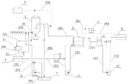
FIG. 1 is a schematic structural diagram of a flue gas desulfurization wastewater treatment system provided by an embodiment of the invention.
The various reference numbers in the drawings are explained below:
1 a surface filter;
201 first line, 202 second line, 203 third line, 204 fourth line, 205 fifth line, 206 sixth line, 207 seventh line, 208 eighth line, 209 ninth line, 210 tenth line, 211 eleventh line, 212 twelfth line, 213 thirteenth line, 214 fourteenth line, 215 fifteenth line, 216 sixteenth line;
3. an oxidation tank;
4. adding an alkali system;
5. a first air supply system;
6. a sewage purification device;
7. a filtrate tank;
8. a reflux pump;
9. a second air supply system;
10. a dustbin;
11. a washing tank;
12. a washing pump;
13. an oxidation circulation pump;
14. a sewage buffer tank;
15. purified water is sent out to the pump.
Detailed Description
To make the objects, technical solutions and advantages of the present invention more apparent, embodiments of the present invention will be described in detail with reference to the accompanying drawings.
An embodiment of the present invention provides a flue gas desulfurization wastewater treatment system, as shown in fig. 1, the system includes: the device comprises a surface filter 1, an oxidation tank 3, an alkali adding system 4, a first air supply system 5 and a sewage purifying device 6; wherein, the surface filter 1 is used for filtering particulate matters in the flue gas desulfurization wastewater, and a filter element of the surface filter 1 is stainless steel or polyethylene; a first inlet of the oxidation tank 3 is communicated with a first outlet of the surface filter 1 through a first pipeline 201; the alkali adding system 4 is communicated with a second inlet of the oxidation tank 3 through a second pipeline 202; the first air supply system 5 is communicated with a third inlet of the oxidation tank 3 through a third pipeline 203; the inlet of the sewage purification apparatus 6 is communicated with the first outlet of the oxidation tank 3 through a fourth line 204.
It should be noted that, due to the operation of the upstream process, when entering the surface filter 1, the flue gas desulfurization wastewater (referred to as "wastewater" for short) has a certain pressure and temperature, for example, when entering the surface filter 1, the pressure is 0.6MPa to 0.8MPa, and the temperature is 60 ℃ to 65 ℃.
The working principle of the flue gas desulfurization wastewater treatment system provided by the embodiment of the invention is described as follows:
waste water firstly enters the surface filter 1, and the surface filter 1 adsorbs particles in the waste water, so that the particles carried by the waste water are removed. Thereafter, the wastewater flows through the first line 201 into the oxidation tank 3; since the alkali adding system 4 is communicated with the second inlet of the oxidation tank 3 through the second pipeline 202, the alkali adding system can deliver alkali supplement into the oxidation tank 3 through the second pipeline 202; since the first air supply system 5 is communicated with the third inlet of the oxidation tank 3 through the third pipeline 203, it can supply the oxidation gas into the oxidation tank 3 through the third pipeline 203; at this time, the wastewater undergoes an oxidation reaction under the action of a supplementary alkali and an oxidizing gas to oxidize sulfite ions in the wastewater into sulfate ions. Then, the wastewater flows through the fourth line 204 into the wastewater purification apparatus 6 for subsequent recycling.
The flue gas desulfurization wastewater treatment system provided by the embodiment of the invention is provided with the surface filter 1, the oxidation tank 3, the alkali adding system 4 and the first air supply system 5 which are respectively communicated with the oxidation tank 3, and the filter element of the surface filter 1 is made of stainless steel or polyethylene, so that the surface filter 1 has strong adsorption capacity and a cleanable function, and can effectively remove particulate matters in wastewater; the first air supply system 5 can inject a large amount of soluble oxidizing gas into the oxidation tank 3, so that the effect of oxidizing sulfite ions in the wastewater is improved, and the sulfite ions in the wastewater can be effectively removed.
In conclusion, the flue gas desulfurization wastewater treatment system provided by the embodiment of the invention can effectively remove particulate matters and sulfite ions in wastewater, does not need to precipitate the wastewater, shortens the treatment time of the wastewater, and improves the treatment efficiency of the wastewater.
When the wastewater flows into the surface filter 1 for filtering, the concentration of the particulate matters in the wastewater may still exceed the amount required by the national standard (for example, the emission standard of pollutants for petroleum refining industry, GB 31570-2015), and at this time, the filtered wastewater needs to be filtered again until the concentration of the particulate matters in the wastewater meets the national standard. Therefore, as shown in fig. 1, the system provided in the embodiment of the present invention further includes: a filtrate tank 7 communicating with the second outlet of the surface filter 1 through a fifth line 205; a reflux pump 8 having an inlet communicating with the filtrate tank 7 through a sixth line 206, the outlet of the reflux pump 8 communicating with the first inlet of the surface filter 1 through a seventh line 207; a first valve is arranged on a first outlet of the surface filter 1, and a second valve is arranged on a second outlet of the surface filter 1.
If the concentration of the particulate matters in the filtered wastewater meets the national standard requirement, opening the first valve, closing the second valve, and enabling the filtered wastewater to flow into the oxidation tank 3 through the first pipeline 201; if the concentration of the particulate matters in the filtered wastewater does not meet the national standard requirement, closing the first valve, opening the second valve and continuously filtering the wastewater until the concentration of the particulate matters in the wastewater meets the national standard requirement.
Alternatively, a first valve may be provided on the first line 201 and a second valve may be provided on the fifth line 205.
It should be noted that the first inlet of the surface filter 1 is not the same round of wastewater that first passes through the inlet of the filter 1.
Wherein, set up the backwash pump 8 between surface filter 1 and filtering ponds 7, can pressurize the waste water of drawing from filtering ponds 7, make waste water possess certain pressure and flow into in surface filter 1, guaranteed going on of follow-up operation.
Therefore, by arranging the filtrate tank 7 and the reflux pump 8 in the system, the wastewater can be effectively filtered, and the concentration of particulate matters in the filtered wastewater is ensured to meet the national standard requirement; but also can pressurize the wastewater to ensure the normal operation of the subsequent operation.
Of course, there are various configurations for filtering the same waste water for several times, for example, a circulation line may be connected between the second outlet and the first inlet of the surface filter 1. The specific structure can be selected according to specific situations.
If the system is provided with the filtrate tank 7, the reflux pump 8, the first valve and the second valve, when the wastewater is circularly filtered, in order to control the first valve and the second valve, the system provided by the embodiment of the invention further comprises: and the automatic control system is electrically connected with the first valve and the second valve respectively and is used for controlling the opening and closing of the first valve and the second valve.
Wherein, the automatic control system can control the opening and closing of the first valve and the second valve according to the filtering time of the surface filter 1 for the wastewater. For example, when the same waste water first passes through the inlet of the surface filter 1, the first valve is closed and the second valve is opened; if the concentration of the particulate matters in the wastewater meets the national standard requirement after 10-20 min, the automatic control system opens the first valve, closes the second valve and allows the filtered wastewater to flow into the oxidation tank 3 through the first pipeline 201.
Further, if the system is provided with a filtrate tank 7, a reflux pump 8, a first valve and a second valve, when the concentration of particulate matters in wastewater meets the national standard requirement, the first valve is opened, the second valve is closed, the wastewater in the filtrate tank 7 becomes smaller, and when the content of the wastewater in the filtrate tank 7 is too low, if the reflux pump 8 is not closed in time, internal parts of the reflux pump 8 are abraded, and the service life of the reflux pump is shortened; but also wastes electricity.
In order to avoid the above situation, a valve capable of controlling the opening and closing of the reflux pump 8 may be disposed on the reflux pump 8 (for example, an inlet or an outlet of the reflux pump 8), and the valve may be automatically controlled so as to be easily controlled, so in the embodiment of the present invention, a third valve is disposed on the reflux pump 8, and the third valve is electrically connected to the automatic control system; and a first liquid level meter is arranged on the inner wall of the filtrate tank 7 and is electrically connected with an automatic control system.
The principle that the automatic control system automatically controls the opening and closing of the third valve is as follows: the first level gauge measures the level of wastewater in the filtrate tank 7 and transmits the measurement result in the form of an electrical signal to the automatic control system, which controls the on and off of the reflux pump 8 based on the received electrical signal.
When waste water flows through surface filter 1 and filters, the particulate matter that it carried can deposit in surface filter 1's the filter core, if not in time clear up the filter core, can influence the adsorption effect of filter core to the particulate matter in the waste water. Then, referring to fig. 1, the system provided in the embodiment of the present invention further includes: a second air supply system 9 communicating with the second inlet of the surface filter 1 through an eighth line 208 for removing the particulate matter inside the surface filter 1; a waste bin 10 communicating with the third outlet of the surface filter 1 for collecting said particles.
The working process for removing the particulate matter in the surface filter 1 is as follows: the second air supply system 9 provides air which flows through the eighth line 208 to the cartridge face of the face filter 1; the particulate matter on the surface of the filter element of the surface filter 1 is detached from the surface of the filter element by the gas pressure and moves through the third outlet of the surface filter 1 into the waste bin 10 to be collected by the waste bin 10.
Wherein, the gas in the second air supply system 9 can be air, which can be provided by other operation processes.
If a certain amount of particles are adsorbed on the filter element of the surface filter 1, the flow rate of the wastewater flowing through the surface filter 1 is reduced, and the pressure difference of the wastewater in the system is increased. Therefore, it is possible to control whether or not the second air supply system 9 supplies the gas into the surface filter 1 based on the differential pressure value.
In order to facilitate the control of the second air supply system 9, a pressure sensor may be disposed on the first pipeline 201, the pressure sensor being electrically connected to an automatic control system, the automatic control system being electrically connected to the second air supply system 9. The working principle of automatically controlling the second air supply system 9 is as follows: the pressure sensor measures the pressure of the wastewater flowing through the first line 201 (or the fourth line 204) and transmits the pressure value in the form of an electrical signal to the automatic control system, which controls the second air supply system 9 in accordance with the electrical signal.
When the pressure sensor measures and detects that the pressure of the wastewater in the first pipeline 201 (or the fourth pipeline 204) is too low, the automatic control system judges that the amount of the deposited particles in the surface filter 1 is too large and needs to process the particles, at the moment, the automatic control system opens the second air supply system 9, the second air supply system 9 provides gas for the surface filter 1, and the particles in the filter element in the surface filter 1 are removed; conversely, the automatic control system shuts off the second air supply system 9, and the second air supply system 9 stops supplying air into the surface filter 1.
It should be noted that, when the second air supply system 9 is in the open state, the third outlet of the surface filter 1 should also be in the open state; and when the second air supply system 9 is in the closed state, the third outlet of the surface filter 1 should also be in the closed state.
Further, if the second air supply system 9 cannot effectively remove the particulate matter in the surface filter 1, the filter element of the surface filter 1 may be treated by water washing, for example, as shown in fig. 1, the system provided by the embodiment of the present invention further includes: a washing tank 11 for washing the particulate matter in the filter 1; a washing pump 12 having an inlet communicating with the outlet of the washing tank 11 through a ninth line 209, the outlet of the washing pump 12 communicating with the third inlet of the surface filter 1 through a tenth line 210; the inlet of the wash tank 11 communicates with the fourth outlet of the surface filter 1 via an eleventh line 211, which eleventh line 211 is provided with a filter valve.
The operation of the washing tank 11 for cleaning the valve element in the surface filter 1 can be described as follows: firstly, closing the filter valve to ensure that the washing tank 11 is not communicated with the fourth outlet of the surface filter 1; the washing pump 12 is turned on, the washing liquid in the washing tank 11 is pumped, and the washing liquid is conveyed into the surface filter 1; then flushing the filter element in the surface filter 1; then, the filter valve is opened, and the washing liquid in the surface filter 1 flows out from the fourth outlet of the surface filter 1 and flows through the eleventh pipeline 211, and meanwhile, the filter valve on the eleventh pipeline 211 filters the particulate matters in the washing liquid; the filtered washing liquid enters the washing tank 11, and then the next round of washing is carried out, and the rest is done in the same way until the valve core in the surface filter 1 is washed clean.
Therefore, the valve core in the surface filter 1 is cleaned on line (namely, the valve core does not need to be taken out of the surface filter 1 and cleaned again) by communicating the washing tank 11 with the washing pump 12 and connecting the washing pump 12 with the surface filter 1, so that the cleaning time is saved; in addition, the eleventh pipeline 211 is communicated between the inlet of the washing tank 11 and the fourth outlet of the surface filter 1, and the filter valve is arranged on the eleventh pipeline 211, so that the valve core of the surface filter 1 can be washed for a plurality of times, and particles in the washing liquid after the valve core is washed can be filtered, and the washing effect of the valve core is improved.
In order to improve the effect of oxidizing sulfite ions in wastewater, an embodiment of the present invention adopts a cyclic oxidation method, and accordingly, as shown in fig. 1, the system provided in the embodiment of the present invention further includes: an oxidation circulation pump 13; an inlet of the oxidation circulation pump 13 is communicated with the second outlet of the oxidation tank 3 through a twelfth line 212, and an outlet of the oxidation circulation pump 13 is communicated with the second line 202 through a thirteenth line 213.
The operation process of the oxidation tank 3 for oxidizing the sulfite ions in the wastewater can be described as follows: the oxidation circulation pump 13 pumps the wastewater in the oxidation tank 3, and the wastewater enters the thirteenth pipeline 213 through the outlet of the oxidation circulation pump 13; while the wastewater flows through the thirteenth line 213, the alkali supplement system 4 adds alkali supplement to the thirteenth line 213 through the second line 202, and the alkali supplement is uniformly mixed with the wastewater; then the mixed liquid composed of the wastewater and the alkali supplement enters the oxidation tank 3, at this time, the first air supply system 5 provides oxidation gas (oxygen or air) into the oxidation tank 3 through a third pipeline 203, and sulfite ions in the wastewater and the alkali supplement perform oxidation reaction under the action of the oxidation gas to generate sulfate ions; and then, if the concentration of the sulfite ions in the wastewater does not meet the national standard requirement, continuing to perform oxidation reaction on the wastewater, namely repeating the operation until the concentration of the sulfite ions in the wastewater meets the national standard requirement.
It is thus clear that through the setting of above-mentioned structure, can carry out the homogeneous mixing with waste water and supplementary alkali, also can carry out oxidation many times to the sulfite ion in the waste water in addition, effectively reduced the concentration of sulfite ion in the waste water, improved the treatment effeciency to waste water.
Wherein, the alkali supplement in the process can be sodium hydroxide or magnesium hydroxide solution; in addition, the first air supply system 5 may be provided as a blower.
Because the concentrations of sulfite ions in different batches of wastewater are different, in order to save the use amount of alkali supplement, the alkali supplement amount conveyed from the alkali supplement system 4 to the thirteenth pipeline 213 can be controlled for different batches of wastewater, and in order to save the operation time, in the embodiment of the present invention, the second pipeline 202 is provided with the fourth valve, and the fourth valve is electrically connected with the automatic control system; a concentration meter is arranged on the twelfth pipeline 212 and is used for detecting the concentration of sulfite ions in the flue gas desulfurization wastewater; the concentration meter is electrically connected with the automatic control system.
The working principle of controlling the alkali supplement amount delivered from the alkali supplement system 4 to the thirteenth pipeline 213 is as follows: the concentration meter detects the concentration of sulfite ions in the wastewater in the twelfth pipeline 212 and transmits the detection result to the automatic control system in the form of an electric signal; the automatic control system adjusts the fourth valve according to the received signal, for example, when the concentration of sulfite ions in the wastewater is small, the fourth valve is adjusted to reduce the flow of the make-up alkali through the fourth valve, and when the concentration of sulfite ions in the wastewater is large, the fourth valve is adjusted to increase the flow of the make-up alkali through the fourth valve.
As shown in fig. 1, the system further includes: a sewage buffer tank 14, wherein the inlet of the sewage buffer tank 14 is communicated with the first outlet of the oxidation tank 3 through a fourteenth pipeline 214; a purified water delivery pump 15 having an inlet connected to the outlet of the wastewater buffer tank 14 via a fifteenth line 215 and an outlet connected to the inlet of the wastewater purification apparatus 6 via a sixteenth line 216. The structure of the system is set, so that the purified wastewater can be temporarily cached, and the purified wastewater can be reasonably utilized; but also can ensure that the purified wastewater flowing into the sewage purification device 6 has certain pressure, so that the wastewater can be conveniently used in the subsequent links needing certain pressure water.
In order to prevent the amount of the purified wastewater in the wastewater buffer tank 14 from being too large or too small, the relationship between the amount of the wastewater in the wastewater buffer tank 14 and the purified wastewater device 6 can be adjusted by means of an automated control. For example, the fifteenth pipeline 215 of the present embodiment is provided with a fifth valve; the fifth valve is electrically connected with the automatic control system; and a second liquid level meter is arranged on the inner wall of the sewage buffer tank 14 and is electrically connected with the automatic control system. The working principle is as follows: the second liquid level meter detects the water level of the purified wastewater in the wastewater buffer tank 14 and transmits the detection result to the automatic control system in the form of an electric signal; the automatic control system adjusts the opening and closing of the fifth valve according to the signal.
The following table is a parameter table of a certain batch of wastewater after being treated by the flue gas desulfurization wastewater treatment system provided by the embodiment of the invention.

Among them, COD (Chemical Oxygen Demand) is an index for indicating the degree of water pollution, and the larger the value is, the water pollution degree is also serious.
As can be seen from the above table, each index in the wastewater meets the national standard requirements, and it can be seen that the flue gas desulfurization wastewater treatment system provided by the embodiment of the invention can effectively remove particulate matters and sulfite ions in the wastewater.
All the above optional technical solutions may be combined arbitrarily to form the optional embodiments of the present disclosure, and are not described herein again.
The above description is only for the purpose of illustrating the preferred embodiments of the present invention and should not be taken as limiting the scope of the present invention, which is intended to cover any modifications, equivalents, improvements, etc. within the spirit and scope of the present invention.
Claims (6)
1. A flue gas desulfurization wastewater treatment system, characterized in that the system comprises:
the surface filter (1) is used for filtering particulate matters in the flue gas desulfurization wastewater, and a filter element of the surface filter (1) is stainless steel or polyethylene;
an oxidation tank (3) with a first inlet communicated with a first outlet of the surface filter (1) through a first pipeline (201);
an alkali addition system (4) communicated with a second inlet of the oxidation tank (3) through a second pipeline (202);
a first air supply system (5) communicated with a third inlet of the oxidation tank (3) through a third pipeline (203);
a sewage purification device (6) with an inlet communicated with the first outlet of the oxidation tank (3) through a fourth pipeline (204);
a filtrate tank (7) communicating with the second outlet of the surface filter (1) through a fifth line (205);
a reflux pump (8) having an inlet communicating with the filtrate tank (7) through a sixth line (206), the outlet of the reflux pump (8) communicating with the first inlet of the surface filter (1) through a seventh line (207);
a first valve is arranged on a first outlet of the surface filter (1), and a second valve is arranged on a second outlet of the surface filter (1); if the concentration of the particulate matters in the wastewater filtered by the surface filter (1) meets the national standard requirement, opening the first valve and closing the second valve, otherwise, closing the first valve and opening the first valve;
a third valve is arranged on the reflux pump (8) and is electrically connected with the automatic control system; a first liquid level meter is arranged on the inner wall of the filtrate tank (7) and is electrically connected with the automatic control system; the first liquid level meter is used for measuring the liquid level of wastewater in the filtrate tank (7) and transmitting the measurement result to the automatic control system in the form of an electric signal, and the automatic control system controls the on or off of the reflux pump (8) based on the received electric signal;
-a second air supply system (9) communicating with a second inlet of the surface filter (1) through an eighth line (208) for removing the particles inside the surface filter (1); the first pipeline (201) is provided with a pressure sensor which is electrically connected with the automatic control system, the automatic control system is electrically connected with the second air supply system (9), wherein the pressure sensor is used for measuring the pressure of the wastewater flowing through the first pipeline (201) or the fourth pipeline (204) and transmitting the pressure to the automatic control system, when the pressure is too low, the automatic control system opens the second air supply system (9), otherwise, the automatic control system closes the second air supply system (9);
a dust bin (10) communicating with a third outlet of the surface filter (1) for collecting the particulate matter within the surface filter (1) removed by the second air supply system (9);
a wash tank (11) for washing the particles in the surface filter (1); a wash pump (12) having an inlet in communication with the outlet of the wash tank (11) through a ninth line (209), the outlet of the wash pump (12) being in communication with the third inlet of the surface filter (1) through a tenth line (210); an inlet of the washing tank (11) is communicated with a fourth outlet of the surface filter (1) through an eleventh pipeline (211), a filter valve is arranged on the eleventh pipeline (211), the filter valve is used for filtering particles in washing liquid, and the washing liquid filtered by the filter valve enters the washing tank (11) to be washed in the next round.
2. The system of claim 1, further comprising: and the automatic control system is electrically connected with the first valve and the second valve respectively and is used for controlling the opening and closing of the first valve and the second valve.
3. The system of claim 1, further comprising: an oxidation circulation pump (13);
the inlet of the oxidation circulating pump (13) is communicated with the second outlet of the oxidation tank (3) through a twelfth pipeline (212), and the outlet of the oxidation circulating pump (13) is communicated with the second pipeline (202) through a thirteenth pipeline (213).
4. The system according to claim 3, characterized in that a fourth valve is arranged on the second line (202), said fourth valve being electrically connected to the automatic control system;
a concentration meter is arranged on the twelfth pipeline (212) and is used for detecting the concentration of sulfite ions in the flue gas desulfurization wastewater;
the concentration meter is electrically connected with the automatic control system.
5. The system of claim 1, further comprising: a sewage buffer tank (14), wherein the inlet of the sewage buffer tank (14) is communicated with the first outlet of the oxidation tank (3) through a fourteenth pipeline (214);
and the inlet of the purified water outward-feeding pump (15) is communicated with the outlet of the sewage buffer tank (14) through a fifteenth pipeline (215), and the outlet of the purified water outward-feeding pump (15) is communicated with the inlet of the sewage purification device (6) through a sixteenth pipeline (216).
6. A system according to claim 5, characterised in that the fifteenth line (215) is provided with a fifth valve; the fifth valve is electrically connected with the automatic control system;
and a second liquid level meter is arranged on the inner wall of the sewage buffer tank (14), and the second liquid level meter is electrically connected with the automatic control system.
Priority Applications (1)
| Application Number | Priority Date | Filing Date | Title |
|---|---|---|---|
| CN201711173292.9A CN109809590B (en) | 2017-11-22 | 2017-11-22 | Flue gas desulfurization effluent disposal system |
Applications Claiming Priority (1)
| Application Number | Priority Date | Filing Date | Title |
|---|---|---|---|
| CN201711173292.9A CN109809590B (en) | 2017-11-22 | 2017-11-22 | Flue gas desulfurization effluent disposal system |
Publications (2)
| Publication Number | Publication Date |
|---|---|
| CN109809590A CN109809590A (en) | 2019-05-28 |
| CN109809590B true CN109809590B (en) | 2022-11-04 |
Family
ID=66601365
Family Applications (1)
| Application Number | Title | Priority Date | Filing Date |
|---|---|---|---|
| CN201711173292.9A Active CN109809590B (en) | 2017-11-22 | 2017-11-22 | Flue gas desulfurization effluent disposal system |
Country Status (1)
| Country | Link |
|---|---|
| CN (1) | CN109809590B (en) |
Citations (2)
| Publication number | Priority date | Publication date | Assignee | Title |
|---|---|---|---|---|
| CN203474554U (en) * | 2013-07-26 | 2014-03-12 | 袁峰 | Wet flue gas desulfurized waste water treatment device |
| CN205856236U (en) * | 2016-07-27 | 2017-01-04 | 中石化炼化工程(集团)股份有限公司 | A kind of wet flue gas desulfurization waste water processing means |
Family Cites Families (4)
| Publication number | Priority date | Publication date | Assignee | Title |
|---|---|---|---|---|
| CN102815808B (en) * | 2011-06-09 | 2015-08-19 | 中国石油化工股份有限公司 | Catalytic cracking flue gas desulfuration waste water treatment process |
| CN103693770B (en) * | 2012-09-28 | 2016-12-07 | 宝钢工程技术集团有限公司 | Purifier and using method thereof for wet flue gas desulfurization waste water |
| CN203741157U (en) * | 2014-03-10 | 2014-07-30 | 中国石油工程建设公司大连设计分公司 | Wet process flue gas desulphurization and washing wastewater treatment device |
| CN204981400U (en) * | 2015-04-30 | 2016-01-20 | 江苏盛泰环境工程有限公司 | Processing apparatus is synthesized to wet flue gas desulfurization waste water |
-
2017
- 2017-11-22 CN CN201711173292.9A patent/CN109809590B/en active Active
Patent Citations (2)
| Publication number | Priority date | Publication date | Assignee | Title |
|---|---|---|---|---|
| CN203474554U (en) * | 2013-07-26 | 2014-03-12 | 袁峰 | Wet flue gas desulfurized waste water treatment device |
| CN205856236U (en) * | 2016-07-27 | 2017-01-04 | 中石化炼化工程(集团)股份有限公司 | A kind of wet flue gas desulfurization waste water processing means |
Also Published As
| Publication number | Publication date |
|---|---|
| CN109809590A (en) | 2019-05-28 |
Similar Documents
| Publication | Publication Date | Title |
|---|---|---|
| CN102826686B (en) | Double-membrane treatment method of iron and steel industrial wastewater | |
| CN102674626B (en) | System and method for treatment and recovery of electronic electroplating wastewater | |
| CN105439326A (en) | Treatment method of chemical nickel-plating wastewater | |
| CN110510780A (en) | It is a kind of that cigarette waste water recycling processing unit and method are washed using STRO device | |
| CN210656480U (en) | Adopt washing cigarette waste water retrieval and utilization processing apparatus of DTRO device | |
| CN109809590B (en) | Flue gas desulfurization effluent disposal system | |
| CN209143930U (en) | A kind of coal fired power plant desulfurization wastewater dechlorination processing unit | |
| CN206872572U (en) | A kind of NF membrane advanced purification system for handling Desulphurization for Coal-fired Power Plant waste water | |
| CN203360177U (en) | Arsenical waste water treatment system | |
| CN215049321U (en) | Advanced oxidation reaction system for wastewater treatment | |
| CN210313897U (en) | Denitration desulfurization circulating water treatment device | |
| CN205653220U (en) | Hospital uses sewage detection processing apparatus | |
| CN213596069U (en) | Water treatment device combining ozone tail gas with ceramic membrane | |
| CN210764746U (en) | Adopt washing cigarette waste water retrieval and utilization processing apparatus of STRO device | |
| CN208949090U (en) | Wastewater treatment equipment | |
| CN106587420A (en) | System and method for removing heavy metals from wastewater | |
| CN210559747U (en) | Industrial heavy metal sewage treatment system | |
| CN107188335A (en) | A kind of method of work with water quality detecting function Efficient intelligent water treatment facilities | |
| CN206289123U (en) | A kind of processing system for metro depot car-washing sewage | |
| CN102515421B (en) | Printing and dyeing wastewater recycling system | |
| CN206345740U (en) | Coal chemical industrial waste water pre-processes degreasing unit | |
| CN110510781A (en) | It is a kind of that cigarette waste water recycling processing unit and method are washed using DTRO device | |
| CN218811092U (en) | Device for treating organic matters in electroplating wastewater | |
| CN110668619A (en) | Lead-zinc industrial mineral processing wastewater treatment device and treatment method | |
| CN205347083U (en) | Processing system of desulfurization waste water |
Legal Events
| Date | Code | Title | Description |
|---|---|---|---|
| PB01 | Publication | ||
| PB01 | Publication | ||
| SE01 | Entry into force of request for substantive examination | ||
| SE01 | Entry into force of request for substantive examination | ||
| GR01 | Patent grant | ||
| GR01 | Patent grant |