CN109802308B - Dustproof electric power cabinet of electric power - Google Patents
Dustproof electric power cabinet of electric power Download PDFInfo
- Publication number
- CN109802308B CN109802308B CN201811641812.9A CN201811641812A CN109802308B CN 109802308 B CN109802308 B CN 109802308B CN 201811641812 A CN201811641812 A CN 201811641812A CN 109802308 B CN109802308 B CN 109802308B
- Authority
- CN
- China
- Prior art keywords
- rotating shaft
- dust
- electric power
- cabinet body
- proof box
- Prior art date
- Legal status (The legal status is an assumption and is not a legal conclusion. Google has not performed a legal analysis and makes no representation as to the accuracy of the status listed.)
- Active
Links
- 230000005540 biological transmission Effects 0.000 claims description 21
- 230000003068 static effect Effects 0.000 claims description 7
- 230000000149 penetrating effect Effects 0.000 claims description 5
- 230000017525 heat dissipation Effects 0.000 abstract description 18
- 238000000605 extraction Methods 0.000 abstract description 14
- 239000000428 dust Substances 0.000 description 23
- 230000001360 synchronised effect Effects 0.000 description 5
- 230000000694 effects Effects 0.000 description 3
- 238000005265 energy consumption Methods 0.000 description 2
- 238000012423 maintenance Methods 0.000 description 2
- 210000005056 cell body Anatomy 0.000 description 1
- 238000004140 cleaning Methods 0.000 description 1
- 230000002349 favourable effect Effects 0.000 description 1
- 238000001914 filtration Methods 0.000 description 1
- 238000000034 method Methods 0.000 description 1
- 238000012986 modification Methods 0.000 description 1
- 230000004048 modification Effects 0.000 description 1
- 238000004804 winding Methods 0.000 description 1
Images


Abstract
The invention discloses an electric power dustproof electric power cabinet, which belongs to the field of electric power cabinets and comprises a cabinet body and a heat dissipation port arranged on one side of the cabinet body, wherein a filter screen is arranged on the outlet side of the heat dissipation port, a dustproof box fixed on the cabinet body is arranged at the heat dissipation port, the dustproof box is of a square structure, one side of the dustproof box, which is connected with the cabinet body, is open and communicated with an inner cavity of the cabinet body, the filter screen is arranged on the opposite side of one side of the dustproof box, which is connected with the cabinet body, an extraction fan and an electrostatic roller set are arranged in the dustproof box, the extraction fan is positioned on one side of the dustproof box, the electrostatic roller set is positioned between the extraction fan and the filter screen, the electrostatic roller set comprises two horizontally arranged friction rollers which are overlapped up and down, rubber sleeves and fur sleeves are alternately and fixedly sleeved on the friction rollers along the length direction of the. The heat dissipation port of the power cabinet provided by the invention has an excellent dustproof function.
Description
Technical Field
The invention relates to the field of electric power cabinets, in particular to an electric power dustproof electric power cabinet.
Background
The electric power cabinet is a common electric power infrastructure, and a large amount of electric power parts are installed in the electric power cabinet, and when the electric power cabinet works, a large amount of heat is generated in the electric power cabinet, so that a heat dissipation window must be arranged on the side wall of the electric power cabinet, the basic structure of the current heat dissipation window is a strip-shaped shutter structure, namely, a group of parallel strip-shaped holes are arranged on each side wall, the upper part of each strip-shaped hole is provided with a strip-shaped eave which is turned downwards and semi-surrounds the strip-shaped hole, and the strip-shaped eave is used for shielding. Although sheltering from the rainwater for the strip window by the strip eaves, nevertheless to the dust, can't be blockked by the strip eaves, and the dust is upwards raised from ground again usually, consequently, get into behind the surrounding area of strip eaves very easily, get into in the strip hole again, can think that the dust that has facilitated more of setting up of strip eaves gets into the electric power cabinet to can cause the harm to internal electric power component. Therefore, it is necessary to provide a dust-proof device at the heat dissipation opening of the power cabinet.
Disclosure of Invention
1. Technical problem to be solved
The technical problem to be solved by the invention is to provide an electric power dustproof cabinet, and a heat dissipation port of the electric power dustproof cabinet has an excellent dustproof function.
2. Technical scheme
In order to solve the problems, the invention adopts the following technical scheme:
an electric power dustproof electric cabinet comprises a cabinet body and a heat dissipation port arranged on one side of the cabinet body, wherein a filter screen is arranged on the outlet side of the heat dissipation port, a dustproof box fixed on the cabinet body is arranged at the position of the heat dissipation port, the dustproof box is of a square structure, one side of the dustproof box, which is connected with the cabinet body, is open and communicated with an inner cavity of the cabinet body, the filter screen is arranged on the opposite side of one side of the dustproof box, which is connected with the cabinet body, an extraction fan and an electrostatic roller set are arranged in the dustproof box, the extraction fan is positioned on one side of the dustproof box, the electrostatic roller set is positioned between the extraction fan and the filter screen, the electrostatic roller set comprises two horizontally arranged friction rollers which are overlapped up and down, rubber sleeves and fur sleeves are fixedly sleeved on the friction rollers along the length direction of the friction rollers alternately at intervals, and the rubber;
the center of the suction fan is provided with a first rotating shaft in a penetrating mode, the first rotating shaft is perpendicular to the length direction of the friction rollers, the front face of the suction fan is parallel to the side face of the dustproof box connecting cabinet body, the first rotating shaft penetrates through the two friction rollers, the friction rollers are provided with annular grooves for the first rotating shaft to penetrate through, the circle centers of the annular grooves are located on the central axis of the friction rollers, and the opposite ends of the rotating shafts, corresponding to the suction fan, are connected to the side, where the filter screen is located, through bearings; a second rotating shaft is fixedly arranged on the center line of the friction roller in a penetrating mode, two ends of the second rotating shaft are connected to the inner wall of the corresponding side of the dust-proof box through a second bearing, a transmission gear which is meshed with each other is fixedly sleeved on one side of each of the second rotating shafts, and the diameter of the transmission gear is equal to the diameter of the end face of the friction roller; and the first rotating shaft and the second rotating shaft are both driven by a driving motor.
Furthermore, a first support plate connected to the side wall of the dust-proof box, on which a second bearing is fixed, is sleeved on the part, located between the suction fan and the electrostatic roller set, of the rotating shaft in a clearance manner, and the first support plate is parallel to the length direction of the friction roller. Based on the bearing I can support one end of the first rotating shaft, the first supporting plate can provide support for the other end side of the first rotating shaft, so that the stability of the first rotating shaft can be guaranteed, and a good foundation can be laid for the stable movement of the exhaust fan.
Further, the inboard of dust-proof box corresponding filter screen corresponds the rigidity of bearing one and is equipped with the bar board of vertical setting, bearing one is fixed on the bar board. Because if the bearing directly fixes on the filter screen can lead to the stability of bearing one not enough, so set up the bar shaped plate and be used for installing bearing one, can ensure the stability of bearing one.
Furthermore, a first bevel gear is fixedly sleeved on one end side of the second rotating shaft, the driving motor is arranged on one side of the first bevel gear, a third rotating shaft parallel to the first rotating shaft is fixed at the free end of an output shaft of the driving motor, a second supporting plate connected to the side wall of the second bearing fixed on the dust-proof box is sleeved on one end, far away from the driving motor, of the third rotating shaft in a clearance type manner, a second bevel gear meshed with the first bevel gear is fixedly sleeved on the third rotating shaft, first belt wheels are fixedly sleeved on the third rotating shaft and the first rotating shaft, and a first transmission belt is arranged between the first belt wheels in a winding manner. The driving motor drives the rotating shaft III to rotate so as to drive the belt wheel I and the bevel gear II to rotate simultaneously, the bevel gear II can drive the bevel gear I to rotate, the bevel gear I drives one rotating shaft II to rotate, and the other rotating shaft II can be driven to synchronously but reversely rotate through the transmission gear, so that the synchronous reverse rotation of the two friction rollers is realized; the first belt wheel can drive the other belt wheel to rotate through the first transmission belt, so that the first rotating shaft is driven to rotate, and the rotating shaft drives the exhaust fan to rotate. One driving motor can drive the suction fan and the electrostatic roller group to act simultaneously, and the full utilization of energy is realized.
As an improvement to the scheme, two end sides of the electrostatic roller group are respectively provided with an exhaust fan, the centers of the two exhaust fans are respectively provided with a first rotating shaft in a penetrating manner, the first rotating shafts are fixedly sleeved with second belt wheels, and a second transmission belt is wound between the second belt wheels. The two exhaust fans are arranged to improve the exhaust effect of the exhaust fans, the two rotating shafts can synchronously rotate in the same direction through the belt wheel II and the transmission II, and therefore the two exhaust fans can be driven only through the original driving mechanism, and energy consumption is saved.
As an improvement to the above scheme, a drawer groove body which is drawn out towards the opposite side of one side of the dust-proof box connected with the cabinet body is arranged in the dust-proof box, the drawer groove body comprises a U-shaped main board and a surface side board corresponding to the outer end side of the dust-proof box, the filter screen is embedded and fixed on the surface side board, a sliding groove for the main board to slide in the horizontal direction is arranged on the inner surface of the dust-proof box, and the suction fan, the electrostatic roller set and a driving mechanism thereof are all arranged in the drawer groove body. The arrangement is realized, so that the suction fan, the electrostatic roller set and the driving mechanism thereof can draw out the dustproof box along with the drawer groove body, thereby facilitating the disassembly, assembly and maintenance of related parts and further facilitating the cleaning of dust adsorbed on the electrostatic roller set.
Further, the bottom of the two sides of the main board is provided with rollers, and the bottom of the sliding groove is matched with the rollers. The arrangement of the idler wheels is convenient for the sliding of the drawer groove body.
Furthermore, a first micro magnetic block is arranged in one side, facing the cabinet body, of the top of the meter side plate, and a second micro magnetic block magnetically attracted with the first micro magnetic block is arranged in one side, facing the meter side plate, of the top of the dust-proof box. The first micro magnetic block and the second micro magnetic block can be attracted together through magnetic attraction when the drawer groove body is completely pushed into the dust-proof box, so that the close attachment between the meter side plate and the dust-proof box can be guaranteed, and the stability of the drawer groove body can be maintained.
3. Advantageous effects
According to the invention, the dustproof box is arranged at the heat dissipation port at one side of the cabinet body of the electric power cabinet, the suction fan and the electrostatic roller set are arranged in the dustproof box, the rotation of the suction fan can generate thrust directed from the inner cavity of the cabinet body to the outlet end of the dustproof box, the suction fan sucks dust and heat in the cabinet body into the dustproof box, and the dust and the heat are discharged out of the electric power cabinet through the filter screen at the outlet end of the dustproof box, and meanwhile, the dust in the external environment is prevented from entering the cabinet body through the heat dissipation port; the electrostatic roller set comprises two horizontally arranged friction rollers which are overlapped up and down, rubber sleeves and fur sleeves are fixedly sleeved on the friction rollers along the length direction of the friction rollers alternately at intervals, and the rubber sleeve on one friction roller is aligned with and contacted with the fur sleeve of the other friction roller. Rubber sleeve and fur cover between two friction rollers rub each other between two friction rollers, can make and all have static on two friction rollers, can adsorb the dust in the dustproof box, even there is the dust in the dustproof box, also can all be adsorbed by the static roller set, can not get into the cabinet internally. Therefore, the heat dissipation port of the electric power cabinet has an excellent dustproof function.
Drawings
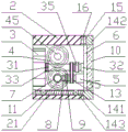
FIG. 1 is a schematic cross-sectional view of the structure of the present invention;
FIG. 2 is a schematic view of the dust box 2 of FIG. 1 and its internal structure;
fig. 3 is a side view of the present invention at a side where the dust box 2 is connected to the cabinet 1;
FIG. 4 is a side view of the drawer channel 14;
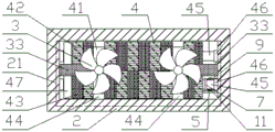
FIG. 5 is a top view of the present invention with the top panel of the dust box 2 removed;
FIG. 6 is an enlarged view of the structure of the area A in FIG. 5;
fig. 7 is an enlarged schematic view of the structure of the region B in fig. 5.
Reference numerals: 1. a cabinet body; 2. a dust-proof box; 21. a chute; 3. an exhaust fan; 31. a first rotating shaft; 32. a first bearing; 33. a first support plate; 34. a second belt wheel; 35. a second transmission belt; 4. an electrostatic roller set; 41. a rubbing roller; 42. a rubber sleeve; 43. a fur cover; 44. an annular groove; 45. a second rotating shaft; 46. a second bearing; 47. a transmission gear; 5. a drive motor; 6. a strip plate; 7. a first bevel gear; 8. a rotating shaft III; 9. a support plate II; 10. filtering with a screen; 11. a second bevel gear; 12. a first belt wheel; 13. a first transmission belt; 14. a drawer groove body; 141. a main board; 142. a surface side plate; 143. A roller; 15. a first micro magnetic block; 16. and a second micro magnetic block.
Detailed Description
The present invention will be described in further detail with reference to the accompanying drawings and examples.
Examples
As shown in fig. 1, the electric power dustproof electric power cabinet comprises a cabinet body 1 and a heat dissipation port arranged on one side of the cabinet body 1, wherein a filter screen 10 is arranged on the outlet side of the heat dissipation port, a dustproof box 2 fixed on the cabinet body 1 is arranged at the heat dissipation port, the dustproof box 2 is of a square structure, the dustproof box 2 is connected with an opening on one side of the cabinet body 1 and communicated with the inner cavity of the cabinet body 1, and the filter screen 10 is arranged on the opposite side of the dustproof box 2 connected with one side of the cabinet body 1; as shown in fig. 2, an extraction fan 3 and an electrostatic roller set 4 are arranged in the dust-proof box 2, the extraction fan 3 is located at one side of the dust-proof box 2 connected with the cabinet 1, the electrostatic roller set 4 is located between the extraction fan 3 and the filter screen 10, as shown in fig. 3 and 5, the electrostatic roller set 4 comprises two horizontally arranged friction rollers 41 which are overlapped up and down, rubber sleeves 42 and fur sleeves 43 are fixedly sleeved on the friction rollers 41 along the length direction of the friction rollers in an alternating interval manner, and the rubber sleeve 42 on one friction roller 41 is aligned with and contacted with the fur sleeve 43 of the other friction roller 41;
as shown in fig. 2 and 5, a first rotating shaft 31 penetrates through the center of the suction fan 3, the first rotating shaft 31 is perpendicular to the length direction of the friction rollers 41, the front surface of the suction fan 3 is parallel to the side surface of the dust-proof box 2 connected with the cabinet 1, the first rotating shaft 31 penetrates through the space between the two friction rollers 41, annular grooves 44 for the first rotating shaft 31 to penetrate through are formed in the friction rollers 41, the center of the annular grooves 44 is located on the central axis of the friction rollers 41, and as shown in fig. 2, 4 and 6, the opposite end of the first rotating shaft 31, corresponding to the suction fan 3, is connected to the side where the filter screen 10 is located through a first bearing 32; as shown in fig. 3 and 5, a second rotating shaft 45 is fixedly arranged on the center line of the friction roller 41 in a penetrating manner, two ends of the second rotating shaft 45 are connected to the inner wall of the corresponding side of the dust-proof box 2 through a second bearing 46, a transmission gear 47 which is meshed with each other is fixedly sleeved on one side of each of the two second rotating shafts 45, and the diameter of the transmission gear 47 is equal to the diameter of the end face of the friction roller 41; the first rotating shaft 31 and the second rotating shaft 45 are both driven by a driving motor 5.
In this embodiment, as shown in fig. 3 and 5, a portion of the first rotating shaft 31 between the suction fan 3 and the electrostatic roller set 4 is sleeved with a first support plate 33 connected to a side wall of the dust-proof box 2 to which a second bearing 46 is fixed, and the first support plate 33 is parallel to the length direction of the friction roller 41. Based on the first bearing 32 capable of supporting one end of the first rotating shaft 31, the first support plate 33 can provide support for the other end side of the first rotating shaft 31, so that the stability of the first rotating shaft 31 can be guaranteed, and a good foundation can be laid for the stable movement of the exhaust fan 3.
In this embodiment, as shown in fig. 2, 4 and 5, a strip-shaped plate 6 vertically disposed is fixed at a position corresponding to a first bearing 32 on the inner side of the filter screen 10 of the dust-proof box 2, and the first bearing 32 is fixed on the strip-shaped plate 6. Since the first bearing 32 may have insufficient stability if the first bearing 32 is directly fixed to the filter screen 10, the strip-shaped plate 6 is used to mount the first bearing 32, so as to ensure the stability of the first bearing 32.
In this embodiment, as shown in fig. 2, 3, and 7, a first bevel gear 7 is fixedly sleeved on one end side of one second rotating shaft 45, the driving motor 5 is disposed on one side of the first bevel gear 7, a third rotating shaft 8 parallel to the first rotating shaft 31 is fixed at a free end of an output shaft of the driving motor 5, a second supporting plate 9 connected to a side wall of the second bearing 46 fixed on the dust-proof box 2 is intermittently sleeved on one end of the third rotating shaft 8 far away from the driving motor 5, a second bevel gear 11 engaged with the first bevel gear 7 is fixedly sleeved on the third rotating shaft 8, first belt wheels 12 are fixedly sleeved on both the third rotating shaft 8 and the first rotating shaft 31, and a first transmission belt 13 is wound between the two first belt wheels 12. The driving motor 5 drives the rotating shaft III 8 to rotate to drive the belt wheel I12 and the bevel gear II 11 to rotate simultaneously, the bevel gear II 11 can drive the bevel gear I7 to rotate, the bevel gear I7 drives one rotating shaft II 45 to rotate, and the transmission gear 47 can drive the other rotating shaft II 45 to synchronously but reversely rotate, so that the synchronous reverse rotation of the two friction rollers 41 is realized; the first belt wheel 12 can drive the other first belt wheel 12 to rotate through the first transmission belt 13, so as to drive the first rotating shaft 31 to rotate, and the first rotating shaft 31 drives the exhaust fan 3 to rotate. The driving motor 5 can drive the suction fan 3 and the electrostatic roller group 4 to act at the same time, thus realizing the full utilization of energy.
In this embodiment, as shown in fig. 3, two end sides of the electrostatic roller set 4 are respectively provided with one extraction fan 3, the centers of the two extraction fans 3 are respectively provided with a first rotating shaft 31, two first rotating shafts 31 are respectively fixedly sleeved with a second belt wheel 34, and as shown in fig. 5, a second transmission belt 35 is wound between the two second belt wheels 34. Set up two extraction fans 3 and can promote the exhaust effect of extraction fan 3, and can make two synchronous syntropy rotations of two pivot one 31 through band pulley two 34 and transmission two, and then only need original actuating mechanism can drive two extraction fans 3, be favorable to practicing thrift the energy consumption.
In this embodiment, as shown in fig. 1, fig. 2 and fig. 4, a drawer groove 14 is provided in the dust-proof box 2 and is drawn out to the opposite side of one side of the dust-proof box 2 connected to the cabinet 1, the drawer groove 14 includes a u-shaped main plate 141 and a surface side plate 142 corresponding to the outer end side of the dust-proof box 2, the filter net 10 is embedded and fixed on the surface side plate 142, a sliding groove for sliding the main plate 141 in the horizontal direction is provided on the inner surface of the dust-proof box 2, and the suction fan 3, the electrostatic roller set 4 and the driving mechanism thereof are all installed in the drawer groove 14. Set up like this for suction fan 3, electrostatic roller set 4 and actuating mechanism can take out dust-proof box 2 along with drawer cell body 14, thereby be convenient for the dismouting and the maintenance of relevant part, still be convenient for clear up the dust that adsorbs on the electrostatic roller set.
In this embodiment, as shown in fig. 2 and fig. 4, rollers 143 are disposed at the bottoms of the two sides of the main plate 141, and the bottoms of the sliding grooves are adapted to the rollers 143. The rollers 143 facilitate sliding movement of the drawer slide 14.
In the present embodiment, as shown in fig. 2, a first micro magnetic block 15 is disposed inside the top of the front side plate 142 facing the cabinet 1, and a second micro magnetic block 16 magnetically attracted to the first micro magnetic block 15 is disposed inside the dust box 2. The first micro magnetic block 15 and the second micro magnetic block 16 can be attracted together through magnetic attraction when the drawer groove body 14 is completely pushed into the dust-proof box 2, so that the close attachment between the watch side plate 142 and the dust-proof box 2 can be guaranteed, and the stability of the drawer groove body 14 can be maintained.
The specific application process of the dustproof electric power cabinet is as follows:
after the driving motor 5 is started, the rotating shaft III 8 is driven to rotate, the rotating shaft III 8 drives the belt wheel I12 and the bevel gear II 11 on the rotating shaft III to rotate, the bevel gear II 11 can drive the bevel gear I7 to rotate, the belt wheel I12 can drive the other belt wheel I12 to rotate through the driving belt I13, so that the rotating shaft I31 is driven to rotate, the rotating shaft I31 drives the suction fan 3 to rotate, thrust directed to the side where the filter screen 10 is located from the inner cavity of the cabinet body 1 is generated, the suction fan 3 sucks dust and heat in the cabinet body 1 into the dust-proof box 2 and blows the dust and heat to the side where the filter screen 10 is located, so that the dust and the heat are discharged out of the electric power cabinet through the filter screen 10, and; bevel gear 7 drives a second 45 rotations of pivot, can drive another second 45 rotations of pivot through drive gear 47 and carry out synchronous but reverse rotation, realized two synchronous reverse rotations of friction roller 41 promptly, rubber sleeve 42 and fur sleeve 43 between two friction rollers 41 rub each other between two friction rollers 41, make and all have static on two friction rollers 41, can adsorb the dust in dust proof box 2, even there is the dust in dust proof box 2, also all can be adsorbed by static roller set 4, can not get into in the cabinet body 1.
According to the invention, the dust in the electric power cabinet can be discharged, and the dust in the external environment can be better prevented from entering the cabinet body from the heat dissipation port, so that the electric power cabinet has an excellent dustproof function.
It should be understood by those skilled in the art that the above embodiments are only for illustrating the present invention and are not to be used as a limitation of the present invention, and that changes and modifications to the above embodiments are within the scope of the claims of the present invention as long as they are within the spirit and scope of the present invention.
Claims (8)
1. The utility model provides an electric power dustproof electric power cabinet, includes the cabinet body (1) and locates the thermovent of the cabinet body (1) one side, the thermovent outlet side is equipped with filter screen (10), its characterized in that, thermovent department is equipped with dust-proof box (2) of fixing on the cabinet body (1), dust-proof box (2) are the square body structure, the uncovered and intercommunication cabinet body (1) inner chamber in one side of the cabinet body is connected to dust-proof box (2), filter screen (10) are located the opposite side of one side that dust-proof box (2) connect the cabinet body (1), be equipped with suction fan (3) and static roller set (4) in dust-proof box (2), suction fan (3) are located one side that dust-proof box (2) connect the cabinet body (1), static roller set (4) are located between suction fan (3) and filter screen (10), static roller set (4) are including two friction roller (41) that transversely set up that overlap from top to bottom, rubber sleeves (42) and fur sleeves (43) are fixedly sleeved on the friction rollers (41) along the length direction of the friction rollers alternately at intervals, and the rubber sleeve (42) on one friction roller (41) is aligned with and contacted with the fur sleeve (43) of the other friction roller (41);
a first rotating shaft (31) penetrates through the center of the suction fan (3), the first rotating shaft (31) is perpendicular to the length direction of the friction rollers (41), the front face of the suction fan (3) is parallel to the side face of the dust-proof box (2) connected with the cabinet body (1), the first rotating shaft (31) penetrates through the space between the two friction rollers (41), annular grooves (44) for the first rotating shaft (31) to penetrate through are formed in the friction rollers (41), the circle center of each annular groove (44) is located on the central axis of each friction roller (41), and the opposite ends, corresponding to the suction fan (3), of the first rotating shaft (31) are connected to the side where the filter screen (10) is located through a first bearing (32); a second rotating shaft (45) is fixedly arranged on the central line of the friction roller (41) in a penetrating mode, two ends of the second rotating shaft (45) are connected to the inner wall of the corresponding side of the dust-proof box (2) through a second bearing (46), transmission gears (47) which are meshed with each other are fixedly sleeved on one side of each of the two second rotating shafts (45), and the diameter of each transmission gear (47) is equal to the diameter of the end face of the friction roller (41); the first rotating shaft (31) and the second rotating shaft (45) are driven by a driving motor (5).
2. An electric dust-proof electric cabinet according to claim 1, characterized in that the part of the first rotating shaft (31) between the suction fan (3) and the electrostatic roller set (4) is sleeved with a first support plate (33) connected to the side wall of the dust-proof box (2) fixed with a second bearing (46), and the first support plate (33) is parallel to the friction roller (41).
3. The electric power dustproof electric power cabinet according to claim 1, wherein a vertically arranged strip-shaped plate (6) is fixed on the inner side of the dustproof box (2) corresponding to the filter screen (10) at a position corresponding to the first bearing (32), and the first bearing (32) is fixed on the strip-shaped plate (6).
4. The electric power dustproof electric power cabinet according to claim 1, wherein one end side of one rotating shaft II (45) is fixedly sleeved with a bevel gear I (7), the driving motor (5) is arranged on one side of the bevel gear I (7), a rotating shaft III (8) parallel to the rotating shaft I (31) is fixed at the free end of an output shaft of the driving motor (5), one end of the rotating shaft III (8) far away from the driving motor (5) is sleeved with a support plate II (9) which is connected to the side wall of the dust-proof box (2) and is fixed with a bearing II (46) in a clearance type manner, a second bevel gear (11) meshed with the first bevel gear (7) is fixedly sleeved on the third rotating shaft (8), the third rotating shaft (8) and the first rotating shaft (31) are fixedly sleeved with a first belt wheel (12), and a first transmission belt (13) is wound between the two first belt wheels (12).
5. The electric power dustproof electric power cabinet according to claim 1, wherein two ends of the electrostatic roller group (4) are respectively provided with an exhaust fan (3), the centers of the two exhaust fans (3) are respectively provided with a first rotating shaft (31), the two first rotating shafts (31) are respectively fixedly sleeved with a second belt wheel (34), and a second transmission belt (35) is wound between the two second belt wheels (34).
6. The electric power dustproof electric power cabinet according to any one of claims 1 to 5, wherein a drawer groove (14) which is drawn out to the opposite side of one side of the dust-proof box (2) connected with the cabinet body (1) is arranged in the dust-proof box (2), the drawer groove (14) comprises a U-shaped main board (141) and a surface side board (142) corresponding to the outer end side of the dust-proof box (2), the filter screen (10) is embedded and fixed on the surface side board (142), a sliding groove (21) for the main board (141) to slide in the horizontal direction is arranged on the inner surface of the dust-proof box (2), and the suction fan (3), the electrostatic roller set (4) and a driving mechanism thereof are all arranged in the drawer groove (14).
7. The electric power dustproof electric power cabinet according to claim 6, wherein the bottom of the main board (141) is provided with rollers (143), and the bottom of the sliding groove (21) is matched with the rollers (143).
8. The electric power dustproof electric power cabinet as claimed in claim 6, wherein a first micro magnetic block (15) is arranged in one side of the top of the meter side plate (142) facing the cabinet body (1), and a second micro magnetic block (16) magnetically attracted with the first micro magnetic block (15) is arranged in one side of the top of the dustproof box (2) facing the meter side plate (142).
Priority Applications (1)
| Application Number | Priority Date | Filing Date | Title |
|---|---|---|---|
| CN201811641812.9A CN109802308B (en) | 2018-12-29 | 2018-12-29 | Dustproof electric power cabinet of electric power |
Applications Claiming Priority (1)
| Application Number | Priority Date | Filing Date | Title |
|---|---|---|---|
| CN201811641812.9A CN109802308B (en) | 2018-12-29 | 2018-12-29 | Dustproof electric power cabinet of electric power |
Publications (2)
| Publication Number | Publication Date |
|---|---|
| CN109802308A CN109802308A (en) | 2019-05-24 |
| CN109802308B true CN109802308B (en) | 2021-03-02 |
Family
ID=66558274
Family Applications (1)
| Application Number | Title | Priority Date | Filing Date |
|---|---|---|---|
| CN201811641812.9A Active CN109802308B (en) | 2018-12-29 | 2018-12-29 | Dustproof electric power cabinet of electric power |
Country Status (1)
| Country | Link |
|---|---|
| CN (1) | CN109802308B (en) |
Families Citing this family (2)
| Publication number | Priority date | Publication date | Assignee | Title |
|---|---|---|---|---|
| JP7297716B2 (en) * | 2020-05-29 | 2023-06-26 | 日立チャネルソリューションズ株式会社 | Banknote processing equipment |
| CN111697466B (en) * | 2020-05-29 | 2022-02-18 | 国网河北省电力有限公司邱县供电分公司 | Dirt-proof power equipment box for electric power |
Citations (7)
| Publication number | Priority date | Publication date | Assignee | Title |
|---|---|---|---|---|
| CN203541007U (en) * | 2013-10-10 | 2014-04-16 | 桐乡市神州植绒有限公司 | Electrostatic dust collector for flocked cloth |
| CN204417852U (en) * | 2014-10-15 | 2015-06-24 | 大英县天骄纺织有限公司 | A kind of boiling hot dye machine of weaving cotton cloth with dust arrester |
| CN206524558U (en) * | 2016-10-15 | 2017-09-26 | 国家电网公司 | A kind of Dustproof electric power cabinet |
| CN206685715U (en) * | 2017-02-17 | 2017-11-28 | 刘海明 | A kind of communication box with dedusting cooling function |
| CN107845958A (en) * | 2017-12-14 | 2018-03-27 | 国网山东省电力公司龙口市供电公司 | A kind of dustproof heat radiator for power distribution cabinet |
| CN207320589U (en) * | 2017-10-27 | 2018-05-04 | 国网山东省电力公司蓬莱市供电公司 | A kind of dustproof electric cabinet |
| CN208111948U (en) * | 2018-03-09 | 2018-11-16 | 天津尼凯斯电器设备股份有限公司 | A kind of switchgear with fire-extinguishing function concurrently |
Family Cites Families (2)
| Publication number | Priority date | Publication date | Assignee | Title |
|---|---|---|---|---|
| CN205489041U (en) * | 2016-01-10 | 2016-08-17 | 国网山东省电力公司巨野县供电公司 | Moistureproof and rainproof electric power box |
| CN206022912U (en) * | 2016-10-08 | 2017-03-15 | 广州市白云区嘉淇机电设备厂(普通合伙) | A kind of dust-proof damp proof electric power cabinet |
-
2018
- 2018-12-29 CN CN201811641812.9A patent/CN109802308B/en active Active
Patent Citations (7)
| Publication number | Priority date | Publication date | Assignee | Title |
|---|---|---|---|---|
| CN203541007U (en) * | 2013-10-10 | 2014-04-16 | 桐乡市神州植绒有限公司 | Electrostatic dust collector for flocked cloth |
| CN204417852U (en) * | 2014-10-15 | 2015-06-24 | 大英县天骄纺织有限公司 | A kind of boiling hot dye machine of weaving cotton cloth with dust arrester |
| CN206524558U (en) * | 2016-10-15 | 2017-09-26 | 国家电网公司 | A kind of Dustproof electric power cabinet |
| CN206685715U (en) * | 2017-02-17 | 2017-11-28 | 刘海明 | A kind of communication box with dedusting cooling function |
| CN207320589U (en) * | 2017-10-27 | 2018-05-04 | 国网山东省电力公司蓬莱市供电公司 | A kind of dustproof electric cabinet |
| CN107845958A (en) * | 2017-12-14 | 2018-03-27 | 国网山东省电力公司龙口市供电公司 | A kind of dustproof heat radiator for power distribution cabinet |
| CN208111948U (en) * | 2018-03-09 | 2018-11-16 | 天津尼凯斯电器设备股份有限公司 | A kind of switchgear with fire-extinguishing function concurrently |
Also Published As
| Publication number | Publication date |
|---|---|
| CN109802308A (en) | 2019-05-24 |
Similar Documents
| Publication | Publication Date | Title |
|---|---|---|
| CN109802308B (en) | Dustproof electric power cabinet of electric power | |
| CN204089449U (en) | Arc orbit synchronous drive device and air-conditioning | |
| CN214886376U (en) | Driving device of electric retractable door | |
| CN207728292U (en) | A kind of Intelligent fluorescent grid door curtain | |
| CN219247182U (en) | Dustproof electric power cabinet | |
| CN210069364U (en) | Advertisement display device | |
| CN209978338U (en) | Automatic deashing structure and good wind gap of protecting effect | |
| CN208654394U (en) | A kind of sealing and dustproof fibre distribution box | |
| CN213185141U (en) | Outdoor waterproof weak current security protection device | |
| CN104101073A (en) | Indoor unit of air conditioner | |
| CN112483448A (en) | Novel electric fan | |
| CN114866675A (en) | High dynamic camera and camera lens dust removal structure thereof | |
| CN219344561U (en) | Built-in sunshade equipment | |
| CN209197036U (en) | A kind of Intelligent air purifier | |
| CN207048634U (en) | A kind of device for reducing noise | |
| CN213478163U (en) | Composite window with external sunshade | |
| CN207663186U (en) | Light guide plate, backlight module and display device | |
| CN214850842U (en) | Worm-gear-driven transverse curtain opening and closing motor | |
| CN217545020U (en) | Intelligent household appliance device convenient for replacing network cable interface | |
| CN104080321A (en) | Communication base station fuel battery backup power source controllable air door cabinet | |
| CN204652106U (en) | Duster motor | |
| CN216259696U (en) | Electric integrated energy-saving power device | |
| CN218729447U (en) | Wisdom community parking guiding device | |
| CN205638072U (en) | Rotatable window of coordinated type | |
| CN216721492U (en) | Communication terminal for steel mill acquisition system |
Legal Events
| Date | Code | Title | Description |
|---|---|---|---|
| PB01 | Publication | ||
| PB01 | Publication | ||
| SE01 | Entry into force of request for substantive examination | ||
| SE01 | Entry into force of request for substantive examination | ||
| GR01 | Patent grant | ||
| GR01 | Patent grant |