CN219247182U - Dustproof electric power cabinet - Google Patents
Dustproof electric power cabinet Download PDFInfo
- Publication number
- CN219247182U CN219247182U CN202223224311.5U CN202223224311U CN219247182U CN 219247182 U CN219247182 U CN 219247182U CN 202223224311 U CN202223224311 U CN 202223224311U CN 219247182 U CN219247182 U CN 219247182U
- Authority
- CN
- China
- Prior art keywords
- cabinet body
- power cabinet
- dustproof
- rotating shafts
- cleaning brush
- Prior art date
- Legal status (The legal status is an assumption and is not a legal conclusion. Google has not performed a legal analysis and makes no representation as to the accuracy of the status listed.)
- Withdrawn - After Issue
Links
- 239000000428 dust Substances 0.000 claims abstract description 44
- 238000004140 cleaning Methods 0.000 claims abstract description 22
- 230000007246 mechanism Effects 0.000 claims abstract description 22
- 230000005540 biological transmission Effects 0.000 claims abstract description 15
- 238000007790 scraping Methods 0.000 claims abstract description 10
- 230000000149 penetrating effect Effects 0.000 claims abstract description 3
- 230000001360 synchronised effect Effects 0.000 claims description 14
- 238000005096 rolling process Methods 0.000 claims description 6
- 230000001629 suppression Effects 0.000 claims description 3
- 238000009423 ventilation Methods 0.000 claims description 3
- 230000000694 effects Effects 0.000 description 5
- 230000009471 action Effects 0.000 description 2
- 238000010276 construction Methods 0.000 description 2
- 238000010586 diagram Methods 0.000 description 2
- 230000003993 interaction Effects 0.000 description 2
- 238000000034 method Methods 0.000 description 2
- 230000009286 beneficial effect Effects 0.000 description 1
- 230000007547 defect Effects 0.000 description 1
- 230000017525 heat dissipation Effects 0.000 description 1
- 230000007774 longterm Effects 0.000 description 1
- 239000000463 material Substances 0.000 description 1
- 238000012986 modification Methods 0.000 description 1
- 230000004048 modification Effects 0.000 description 1
Images


Classifications
-
- Y—GENERAL TAGGING OF NEW TECHNOLOGICAL DEVELOPMENTS; GENERAL TAGGING OF CROSS-SECTIONAL TECHNOLOGIES SPANNING OVER SEVERAL SECTIONS OF THE IPC; TECHNICAL SUBJECTS COVERED BY FORMER USPC CROSS-REFERENCE ART COLLECTIONS [XRACs] AND DIGESTS
- Y02—TECHNOLOGIES OR APPLICATIONS FOR MITIGATION OR ADAPTATION AGAINST CLIMATE CHANGE
- Y02A—TECHNOLOGIES FOR ADAPTATION TO CLIMATE CHANGE
- Y02A30/00—Adapting or protecting infrastructure or their operation
- Y02A30/14—Extreme weather resilient electric power supply systems, e.g. strengthening power lines or underground power cables
Landscapes
- Electric Vacuum Cleaner (AREA)
Abstract
The utility model relates to the technical field of electric power cabinets, in particular to a dustproof electric power cabinet, which comprises a cabinet body and a cabinet door rotatably arranged at one side of the cabinet body, wherein a vent is formed in the rear end face of the cabinet body in a penetrating manner, a cleaning brush is fixedly arranged in the vent along the vertical direction, two rotating shafts are rotatably arranged at one side of the cleaning brush along the vertical direction through a transmission mechanism, dust screens are sleeved outside the two rotating shafts together, and scraping plates are rotatably arranged at the bottom of the dust screens along the horizontal direction through a steering mechanism.
Description
Technical Field
The utility model relates to the technical field of power cabinets, in particular to a dustproof power cabinet.
Background
With the development of the age, the living standard of people is continuously improved, the electric power resource is widely applied to life, and in the construction of an electric power infrastructure, an electric power cabinet is common equipment, is a common electric power infrastructure, and can be internally provided with electric power components to provide basic assembly for the electric power construction.
Inside instrument of electric power cabinet can produce a large amount of heat in the during operation inside, in order to protect the instrument of inside loading, can set up the vent on the electric power cabinet generally and dispel the heat, the vent is inside to be installed the dust screen and prevent dust, but in long-term use, the dust screen gathers the dust easily, blocks up the dust screen, needs the staff regularly to dismantle and wash the dust screen, and the clearance is untimely can seriously influence the radiating effect of electric power cabinet, uses inconveniently.
Disclosure of Invention
The utility model aims to solve the defects in the background art and provides a dustproof power cabinet.
In order to achieve the above purpose, the utility model adopts the following technical scheme: the utility model provides a dustproof electric power cabinet, includes the cabinet body and rotates the cabinet door of installing in cabinet body one side, the vent has been run through on the terminal surface behind the cabinet body, the inside cleaning brush that has of vertical direction along the vent, two axis of rotation are installed through drive mechanism rotation in vertical direction along cleaning brush one side, two the axis of rotation outside is equipped with the dust screen in common cover, the scraper blade is installed through steering mechanism rotation along the horizontal direction in the dust screen bottom.
Preferably, the transmission mechanism comprises first synchronous wheels respectively fixedly installed at the top ends of two rotating shafts, the outer sides of the two first synchronous wheels are respectively movably sleeved with a first synchronous belt, and the bottom end of one rotating shaft is provided with a driving mechanism.
Preferably, the driving mechanism comprises a bracket fixedly installed in the cabinet body, one end of the bracket is fixedly provided with a motor, the bottom end of one rotating shaft is fixedly provided with a second synchronous wheel, and the second synchronous wheel is in transmission connection with an output shaft of the motor through a second synchronous belt.
Preferably, the steering mechanism comprises a driving gear fixedly sleeved on the outer side of one of the rotating shafts, the outer edge of the driving gear is meshed with a steering gear, the steering gear is fixedly arranged at one end of a rolling shaft, and a scraping plate is fixedly sleeved on the outer side of the rolling shaft.
Preferably, one end of the scraping plate is fixedly provided with a fixed block, the bottom of the fixed block is fixedly connected with the cabinet body, and one end of the rolling shaft is rotatably arranged inside the fixed block.
Preferably, a plurality of support plates are fixedly arranged in the cabinet body.
Preferably, the dust screen is a flexible dust suppression screen.
Compared with the prior art, the utility model has the following beneficial effects:
according to the utility model, the cleaning brush is arranged in the vent, and the dust screen is arranged on one side of the cleaning brush through the transmission mechanism, so that the dust screen is automatically cleaned through the cleaning brush in the transmission process, the dust screen is prevented from being blocked due to untimely cleaning by staff, the heat dissipation effect of the electric cabinet is influenced, the manpower is reduced, and the cleaning efficiency is improved;
through setting up the scraper blade in the dust screen bottom, make scraper blade and filter screen sharing drive power through steering mechanism, be convenient for clear up the accumulational dust in vent bottom, effectively improve the radiating effect of vent.
Drawings
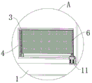
FIG. 1 is a schematic diagram of the overall structure of a dustproof power cabinet according to the present utility model;
FIG. 2 is an enlarged view of the dustproof electric cabinet of FIG. 1A according to the present utility model
FIG. 3 is a schematic view of a dust screen of a dust-proof power cabinet according to the present utility model;
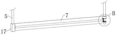
FIG. 4 is a schematic diagram of a scraper of a dustproof power cabinet according to the present utility model;
fig. 5 is an enlarged view of fig. 4B of a dust-proof power cabinet according to the present utility model.
In the figure: 1. a cabinet body; 2. a cabinet door; 3. a vent; 4. a cleaning brush; 5. a rotating shaft; 6. a dust screen; 7. a scraper; 8. a first synchronizing wheel; 9. a first synchronization belt; 10. a bracket; 11. a motor; 12. a second synchronizing wheel; 13. a second timing belt; 14. a drive gear; 15. a steering gear; 16. a roller; 17. a fixed block; 18. and a support plate.
Detailed Description
The following description is presented to enable one of ordinary skill in the art to make and use the utility model. The preferred embodiments in the following description are by way of example only and other obvious variations will occur to those skilled in the art.
The dustproof electric power cabinet comprises a cabinet body 1 and a cabinet door 2 rotatably arranged on one side of the cabinet body 1, a vent 3 is formed in the rear end face of the cabinet body 1 in a penetrating mode, a cleaning brush 4 is fixedly arranged in the vent 3 along the vertical direction, two rotating shafts 5 are rotatably arranged on one side of the cleaning brush 4 along the vertical direction through a transmission mechanism, a dustproof net 6 is sleeved on the outer sides of the two rotating shafts 5, and a scraping plate 7 is rotatably arranged on the bottom of the dustproof net 6 along the horizontal direction through a steering mechanism.
Further, the transmission mechanism comprises first synchronous wheels 8 which are respectively and fixedly arranged at the top ends of the two rotating shafts 5, the outer sides of the two first synchronous wheels 8 are respectively and movably sleeved with a first synchronous belt 9, the bottom end of one rotating shaft 5 is provided with a driving mechanism, and the dust screen 6 is enabled to be transmitted along the horizontal direction through interaction of the first synchronous belt 9 and the two first synchronous wheels 8.
Further, the driving mechanism comprises a support 10 fixedly arranged in the cabinet body 1, a motor 11 is fixedly arranged at one end of the support 10, the motor 11 is vertically arranged, the support 10 can fix the position of the motor 11, a second synchronizing wheel 12 is fixedly arranged at the bottom end of one rotating shaft 5, the second synchronizing wheel 12 is in transmission connection with an output shaft of the motor 11 through a second synchronizing belt 13, and the motor 11 drives the second synchronizing wheel 12 to drive the rotating shaft 5 to rotate.
Further, the steering mechanism comprises a driving gear 14 fixedly sleeved on the outer side of one of the rotating shafts 5, a steering gear 15 is meshed with the outer edge of the driving gear 14, the steering gear 15 is fixedly installed at one end of a roller 16, a scraping plate 7 is fixedly sleeved on the outer side of the roller 16, the scraping plate 7 rotates along the horizontal direction under the driving action of a motor 11 through the interaction of the driving gear 14 and the steering gear 15, dust accumulated at the bottom of the ventilation opening 3 is cleaned, and the scraping plate 7 and the dust screen 6 share the driving force.
Further, one end fixed mounting of scraper blade 7 has fixed block 17, and fixed block 17 is located the inside and bottom and the cabinet body 1 fixed connection of vent 3, and the one end rotation of roller bearing 16 is installed inside fixed block 17, and the setting of fixed block 17 is convenient for fix the position of scraper blade 7.
Further, one side of the dust screen 6 needs to be in contact with the bristles of the cleaning brush 4, so that the dust screen 4 can clean dust adhered to the surface of the dust screen 6 by passing through the cleaning brush 4 in the transmission process of the dust screen 6.
Further, a plurality of support plates 18 are fixedly arranged in the cabinet body 1, so that workers can conveniently rest instruments.
Further, the dust screen 6 is a flexible dust suppression screen, and the dust screen 6 made of the material is firm and wear-resistant and is convenient to clean.
During the use, staff's driving motor 11, under motor 11's driving action, second synchronizing wheel 12 rotates is driven to second synchronizing wheel 13, because second synchronizing wheel 12 fixed mounting is in one of them axis of rotation 5 bottom, and one of them axis of rotation 5 begins to rotate this moment, under the interact at first synchronizing belt 9 and first synchronizing wheel 8, make another axis of rotation 5 rotate, thereby drive dust screen 6 along the horizontal direction beginning transmission, in-process through the cleaning brush 4 of one side, because the brush hair of cleaning brush 4 contacts with dust screen 6, can clear away the dust adhesion on dust screen 6 surface in the transmission process, carry out the self-cleaning to dust screen 6, the fixed suit of scraper blade 7 is on roller 16, the one end fixed mounting of roller 16 has steering gear 15, because one of them axis of rotation 5 outside cover is equipped with driving gear 14, and driving gear 14 and steering gear 15 intermesh, thereby make scraper blade 7 and dust screen 6 share the driving force, in the in-process of dust screen 6 transmission scraper blade 7 rotates, carry out the vent with the dust that will pile up in the bottom of vent 3, this device simple structure, be convenient for carry out the automatic cleaning to 3 bottom and dust screen 6, the dust screen 6 contacts with dust screen 6, can not produce the vent effect of the clean up, the vent is avoided in time, the power saving the work is not to the vent is not guaranteed, the effect of the vent is not really influenced by the personnel's cleaning.
The foregoing has shown and described the basic principles, principal features and advantages of the utility model. It will be understood by those skilled in the art that the present utility model is not limited to the embodiments described above, and that the above embodiments and descriptions are merely illustrative of the principles of the present utility model, and various changes and modifications may be made therein without departing from the spirit and scope of the utility model, which is defined by the appended claims. The scope of the utility model is defined by the appended claims and equivalents thereof.
Claims (7)
1. The utility model provides a dustproof electric power cabinet, includes cabinet body (1) and rotates cabinet door (2) of installing in cabinet body (1) one side, its characterized in that: the novel cleaning brush is characterized in that a ventilation opening (3) is formed in the rear end face of the cabinet body (1) in a penetrating mode, a cleaning brush (4) is fixedly arranged in the ventilation opening (3) in the vertical direction, two rotating shafts (5) are rotatably arranged on one side of the cleaning brush (4) in the vertical direction through a transmission mechanism, dust screens (6) are sleeved on the outer sides of the two rotating shafts (5) in a sleeved mode, and scraping plates (7) are rotatably arranged at the bottoms of the dust screens (6) in the horizontal direction through a steering mechanism.
2. A dustproof power cabinet according to claim 1, characterized in that: the transmission mechanism comprises first synchronous wheels (8) which are respectively and fixedly arranged at the top ends of two rotating shafts (5), the outer sides of the two first synchronous wheels (8) are respectively and movably sleeved with a first synchronous belt (9), and a driving mechanism is arranged at the bottom end of one rotating shaft (5).
3. A dustproof power cabinet according to claim 2, characterized in that: the driving mechanism comprises a bracket (10) fixedly arranged in the cabinet body (1), one end of the bracket (10) is fixedly provided with a motor (11), one of the bottom ends of the rotating shafts (5) is fixedly provided with a second synchronizing wheel (12), and the second synchronizing wheel (12) is in transmission connection with an output shaft of the motor (11) through a second synchronizing belt (13).
4. A dustproof power cabinet according to claim 1, characterized in that: the steering mechanism comprises a driving gear (14) fixedly sleeved on the outer side of one rotating shaft (5), a steering gear (15) is meshed with the outer edge of the driving gear (14), the steering gear (15) is fixedly installed at one end of a rolling shaft (16), and a scraping plate (7) is fixedly sleeved on the outer side of the rolling shaft (16).
5. A dustproof power cabinet according to claim 4, wherein: one end of the scraping plate (7) is fixedly provided with a fixed block (17), the bottom of the fixed block (17) is fixedly connected with the cabinet body (1), and one end of the rolling shaft (16) is rotatably arranged inside the fixed block (17).
6. A dustproof power cabinet according to claim 1, characterized in that: a plurality of supporting plates (18) are fixedly arranged in the cabinet body (1).
7. A dustproof power cabinet according to claim 1, characterized in that: the dustproof net (6) is a flexible dust suppression net.
Priority Applications (1)
| Application Number | Priority Date | Filing Date | Title |
|---|---|---|---|
| CN202223224311.5U CN219247182U (en) | 2022-12-02 | 2022-12-02 | Dustproof electric power cabinet |
Applications Claiming Priority (1)
| Application Number | Priority Date | Filing Date | Title |
|---|---|---|---|
| CN202223224311.5U CN219247182U (en) | 2022-12-02 | 2022-12-02 | Dustproof electric power cabinet |
Publications (1)
| Publication Number | Publication Date |
|---|---|
| CN219247182U true CN219247182U (en) | 2023-06-23 |
Family
ID=86804244
Family Applications (1)
| Application Number | Title | Priority Date | Filing Date |
|---|---|---|---|
| CN202223224311.5U Withdrawn - After Issue CN219247182U (en) | 2022-12-02 | 2022-12-02 | Dustproof electric power cabinet |
Country Status (1)
| Country | Link |
|---|---|
| CN (1) | CN219247182U (en) |
Cited By (1)
| Publication number | Priority date | Publication date | Assignee | Title |
|---|---|---|---|---|
| CN116507098A (en) * | 2023-06-25 | 2023-07-28 | 南方电网数字平台科技(广东)有限公司 | Digital twin power grid data transmission device |
-
2022
- 2022-12-02 CN CN202223224311.5U patent/CN219247182U/en not_active Withdrawn - After Issue
Cited By (2)
| Publication number | Priority date | Publication date | Assignee | Title |
|---|---|---|---|---|
| CN116507098A (en) * | 2023-06-25 | 2023-07-28 | 南方电网数字平台科技(广东)有限公司 | Digital twin power grid data transmission device |
| CN116507098B (en) * | 2023-06-25 | 2023-09-19 | 南方电网数字平台科技(广东)有限公司 | Digital twin power grid data transmission device |
Similar Documents
| Publication | Publication Date | Title |
|---|---|---|
| CN219247182U (en) | Dustproof electric power cabinet | |
| CN218478837U (en) | Carding machine apron cleaning device | |
| CN216064467U (en) | Front-mounted cleaning mechanism for liquid crystal display screen | |
| CN214069192U (en) | Energy-saving intelligent power distribution cabinet | |
| CN212124496U (en) | Printing roller cooling and cleaning device for printing equipment | |
| CN210431208U (en) | Switching power supply with dust removal structure | |
| CN110711731B (en) | Photovoltaic board cleaning device | |
| CN215142920U (en) | Dust collecting equipment for liquid crystal display production and packaging | |
| CN112246725A (en) | Environment-friendly baffle cleaning device for municipal construction | |
| CN110729960A (en) | Self-cleaning photovoltaic power generation equipment | |
| CN221149594U (en) | Dynamic canvas machine convenient to clean | |
| CN214412661U (en) | Cleaning device for photovoltaic solar panel | |
| CN216827421U (en) | Liquid crystal display with efficient protection | |
| CN216937206U (en) | Automatic cleaning device for LED display screen | |
| CN219570452U (en) | Fan with self-cleaning structure | |
| CN218547891U (en) | Liquid crystal display frame with good heat dissipation performance | |
| CN213322381U (en) | A clearance protector for wisdom blackboard | |
| CN220791409U (en) | Dustproof dust removal assembly of gear box air cooler | |
| CN221629215U (en) | Electromechanical device mounting rack | |
| CN216383522U (en) | Automatic alarm monitoring equipment | |
| CN219351457U (en) | Motor with self-cleaning structure | |
| CN220985618U (en) | Photovoltaic power generation board support | |
| CN215861654U (en) | Noise reducing device for primary driving gear of clutch | |
| CN212161155U (en) | Dustproof machine tool signal display terminal based on Internet of things | |
| CN215903674U (en) | Dust extraction is used in panel processing |
Legal Events
| Date | Code | Title | Description |
|---|---|---|---|
| GR01 | Patent grant | ||
| GR01 | Patent grant | ||
| AV01 | Patent right actively abandoned |
Granted publication date: 20230623 Effective date of abandoning: 20231213 |
|
| AV01 | Patent right actively abandoned |
Granted publication date: 20230623 Effective date of abandoning: 20231213 |
|
| AV01 | Patent right actively abandoned | ||
| AV01 | Patent right actively abandoned |