CN109801533B - Electrician and electronics simulation training device convenient to adjust and fix - Google Patents
Electrician and electronics simulation training device convenient to adjust and fix Download PDFInfo
- Publication number
- CN109801533B CN109801533B CN201910254957.1A CN201910254957A CN109801533B CN 109801533 B CN109801533 B CN 109801533B CN 201910254957 A CN201910254957 A CN 201910254957A CN 109801533 B CN109801533 B CN 109801533B
- Authority
- CN
- China
- Prior art keywords
- rod
- plate
- supporting plate
- fixing
- convenient
- Prior art date
- Legal status (The legal status is an assumption and is not a legal conclusion. Google has not performed a legal analysis and makes no representation as to the accuracy of the status listed.)
- Active
Links
Images


Abstract
The invention discloses an electrician and electronics simulated training device convenient to adjust, fix and use, which comprises a stand and a fixing frame, wherein an inner cavity is formed in the stand, the top end of a guide rod is connected with a ground wire, the bottom end surface of the stand is provided with an installation groove, the outer surface of the adjusting rod is provided with a detention area, the top end of the installation groove is connected with an installation rod, a support rod is fixed on the outer side of an upper connecting rod, the rear side of the inner side of the fixing frame is connected with a cable, and the rear side of the fixing plate is provided with a. This real device of instructing of electrician electron with simulation convenient to adjust fixed use is convenient for carry out the regulation of platen according to the concrete specification of circuit board and real standard operation requirement, is convenient for guarantee the stability of pallet, can carry out stable fixed to the circuit board, is favorable to guaranteeing to instruct the stability of operation going on of instructing, can guarantee to the fixed regular of cable, is convenient for instruct the operation panel to examine and repair after experimental use in fact, is favorable to using for a long time.
Description
Technical Field
The invention relates to the technical field of electrician and electronics, in particular to an electrician and electronics simulation training device convenient to adjust, fix and use.
Background
Along with the popularization of electric power application, the attention degree of people to the technology of electricians and electronics is higher and higher, so in the teaching of the electricians and electronics technology of various colleges and universities, in order to ensure the teaching quality, teaching operation is mostly carried out in a mode of combining theoretical teaching and practical training operation, the practical training operation is beneficial to enhancing the understanding degree of students on the electricians and electronics technology, and is beneficial to helping the students to stretch into the practical life of understanding and knowing various components and parts in the field of electricians and electronics, and therefore the development of the simulation practical training device for electricians and electronics is indispensable;
however, when the simulation training device for electrician and electronics in the background of the prior art is used, certain problems still exist, such as:
1. the selection of a bedplate of the stand is inconvenient, and the bedplate is inconvenient to adjust according to the specific specification of the circuit board and the practical training operation requirement;
2. the stability of the stand is not convenient to guarantee, the circuit board cannot be stably fixed, and the stable operation of the practical training operation is not guaranteed;
3. the cable cannot be fixed regularly, so that the cable is inconvenient to overhaul after the practical training operating platform is used in an experiment and is not beneficial to long-term use;
therefore, we propose a simulation training device for electricians and electronics, which is convenient for adjusting and fixing use, so as to solve the problems mentioned above.
Disclosure of Invention
The invention aims to provide an electrician and electronic simulation practical training device convenient to adjust, fix and use, and aims to solve the problems that the conventional electrician and electronic simulation practical training device provided by the background art is inconvenient to select a table plate of a table, adjust the table plate according to the specific specification of a circuit board and practical training operation requirements, ensure the stability of the table, stably fix the circuit board, ensure the stable practical training operation, regularly fix a cable, overhaul the practical training operation table after being used in an experiment and use and be not beneficial to long-term use.
In order to achieve the purpose, the invention provides the following technical scheme: a simulation training device for electricians and electronics convenient to adjust, fix and use comprises a stand and a fixing frame, wherein an inner cavity is formed in the stand, a guide rod positioned above the inner cavity is connected to the top end of the stand, a ground wire is connected to the top end of the guide rod, a stand plate is arranged on the outer side of the guide rod, a mounting groove is formed in the bottom end face of the stand plate, a leveling block is arranged in the mounting groove, an anti-static stand surface layer is connected to the top end face of the stand plate, an adjusting rod positioned at the top of the inner cavity is arranged below the stand plate, a first support plate is connected to the outer side of the adjusting rod, a second support plate is arranged on the left side of the first support plate, a detention area is arranged on the outer surface of the adjusting rod, a sliding rod which is also positioned at the top of the inner cavity, the outer side of the adjusting rod is provided with detention areas with smooth outer surfaces at equal intervals, transmission structures are formed among the adjusting rod, the first supporting plate and the second supporting plate, the width of the first supporting plate is not larger than that of the detention areas, the width of the detention areas is not larger than that of the second supporting plate, and meanwhile, the top end surfaces of the first supporting plate and the second supporting plate are flush with the bottom end surface of the bedplate;
the top end of the mounting groove is connected with a mounting rod, the top end of the mounting rod is provided with an upper connecting rod, a supporting rod is fixed on the outer side of the upper connecting rod, the inner side of the supporting rod is rotatably connected with a pressing plate, and the outer side of the pressing plate is connected with a rubber pad in a sticking manner;
the utility model discloses a wire drawing machine, including frame, rack, threading device, fixed roller, line hole, inserted bar, fixed block and connecting block, the mount is fixed on the rear side top of pallet, and the inboard of mount is connected with the panel board, the inboard rear side of panel board is connected with the cable, and the outside of cable is provided with the fixed plate that is located the inside of mount, threading device is installed to the rear side of fixed plate, and threading device includes fixed roller, line hole, inserted bar, fixed block and connecting block, the line hole has been seted up to the inside of fixed roller, and the top of fixed roller is connected with the inserted bar, the fixed block sets up in the outside of fixed roller, and the outside of fixed block is connected with the connecting block.
Preferably, the top end of the inner side of the stand is rotatably connected with guide rods at equal intervals, the top ends of the guide rods are all in contact with the ground wire, and the bedplate forms a turnover structure on the inner side of the stand through the guide rods.
Preferably, the front end and the rear end of the bedplate are of inclined plane structures of 45 degrees, the bedplate single bodies are tightly attached to each other front and back, and the upper end face and the lower end face of the bedplate single bodies are arranged in a flush mode.
Preferably, the mounting grooves are uniformly distributed on the bottom end face of the bedplate, the mounting grooves and the leveling blocks are correspondingly arranged one by one, and the mounting grooves are in telescopic connection with the leveling blocks through springs.
Preferably, the top end of the inner side of the mounting groove is of a threaded structure, the mounting groove is tightly attached to the leveling block, and the sum of the natural length of the spring and the thickness of the leveling block is equal to the depth of the mounting groove.
Preferably, a disassembly connection structure is correspondingly formed between the installation rod and the installation groove, a telescopic structure is formed between the installation rod and the upper connecting rod, and a vertical integrated structure is formed between the upper connecting rod and the supporting rod.
Preferably, the fixing frame, the instrument panel and the cover plate are fixedly connected through bolts, the fixing plate on the inner side of the instrument panel is of a porous structure, and the bottom end of the cable penetrates through the fixing plate and is connected with the junction box.
Preferably, the fixed roller is connected with the fixing frame through the inserted bar, the wire holes are formed in the fixed roller at equal intervals, the inserted bar is connected with the connecting block through the fixed roller, and the connecting block is in threaded connection with the fixing block.
Compared with the prior art, the invention has the beneficial effects that: the simulation practical training device for electrician and electronics convenient to adjust, fix and use is convenient for adjusting the bedplate according to the specific specification of the circuit board and the practical training operation requirement, is convenient for ensuring the stability of the bedplate, can stably fix the circuit board, is beneficial to ensuring the stable operation of the practical training operation, can ensure the regular fixation of cables, is convenient for overhauling after the practical training operation platform is used in an experiment, and is beneficial to long-term use;
1. the bedplate can be conveniently rotated through the guide rod, and meanwhile, the front end surface and the rear end surface of the bedplate are of 45-degree inclined structures, so that the lamination between the bedplate monomers can be conveniently ensured, the top surface or the bottom surface of the bedplate can be selectively used conveniently, the working use is convenient, and the anti-static bedplate layer and the ion fan are used, so that the anti-static electricity is conveniently carried out, and the stability of the practical training operation is conveniently ensured;
2. the positions of the first supporting plate and the second supporting plate can be conveniently adjusted through rotation of the adjusting rod, the first supporting plate can be conveniently distributed at equal intervals through arrangement of the detention area, meanwhile, the width of the second supporting plate is larger than that of the detention area, the second supporting plate can be conveniently moved, the first supporting plate and the second supporting plate can be conveniently recovered, and the bedplate can be conveniently supported and conveniently used in practical training through the adhesion between the first supporting plate and the bedplate and the bottom surface of the bedplate;
3. through the inside fixed plate that is the porous structure volume of mount be convenient for run through of cable to be convenient for regular of cable, the bottom of cable can run through in the downthehole of fixed roll inside simultaneously, through 2 threading devices of group that set up, is convenient for carry out the arrangement of circuit, so that examine and repair after practical training operation panel is tested and is used, be favorable to long-term the use.
Drawings
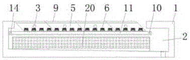
FIG. 1 is a schematic front view of the present invention;
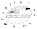
FIG. 2 is a side sectional view of the stand of the present invention;
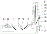
FIG. 3 is a side sectional view of the fixing frame of the present invention;
FIG. 4 is an enlarged view of portion A of FIG. 1 according to the present invention;
FIG. 5 is an enlarged view of portion B of FIG. 3 according to the present invention;
FIG. 6 is a schematic view of a sectional view of the stand according to the present invention;
fig. 7 is a schematic structural view of the threading device of the present invention.
In the figure: 1. a stand; 2. an inner cavity; 3. a guide bar; 4. a ground wire; 5. a platen; 6. mounting grooves; 7. a spring; 8. flattening the whole block; 9. an antistatic table top layer; 10. adjusting a rod; 11. a first supporting plate; 12. a second supporting plate; 13. a stagnant zone; 14. a slide bar; 15. mounting a rod; 16. an upper connecting rod; 17. a strut; 18. pressing a plate; 19. a rubber pad; 20. an ion blower; 21. a fixed mount; 22. an instrument panel; 23. a cable; 24. a fixing plate; 25. a threading device; 2501. a fixed roller; 2502. a wire hole; 2503. inserting a rod; 2504. a fixed block; 2505. connecting blocks; 26. a junction box; 27. and (7) a cover plate.
Detailed Description
The technical solutions in the embodiments of the present invention will be clearly and completely described below with reference to the drawings in the embodiments of the present invention, and it is obvious that the described embodiments are only a part of the embodiments of the present invention, and not all of the embodiments. All other embodiments, which can be derived by a person skilled in the art from the embodiments given herein without making any creative effort, shall fall within the protection scope of the present invention.
Referring to fig. 1-7, the present invention provides a technical solution: an electrician and electronics simulation training device convenient to adjust and fix for use comprises a stand 1, an inner cavity 2, a guide rod 3, a ground wire 4, a stand plate 5, a mounting groove 6, a spring 7, a leveling block 8, an anti-static stand surface layer 9, an adjusting rod 10, a first supporting plate 11, a second supporting plate 12, a detention area 13, a sliding rod 14, a mounting rod 15, an upper connecting rod 16, a supporting rod 17, a pressing plate 18, a rubber pad 19, an ion fan 20, a fixing frame 21, a meter panel 22, a cable 23, a fixing plate 24, a threading device 25, a junction box 26 and a cover plate 27, wherein the inner cavity 2 is arranged in the stand 1, the guide rod 3 positioned above the inner cavity 2 is connected to the top end of the stand 1, the ground wire 4 is connected to the top end of the guide rod 3, the stand plate 5 is arranged on the outer side of the guide rod 3, the mounting groove 6 is arranged on the bottom end face of, an adjusting rod 10 positioned at the top of the inner cavity 2 is arranged below the bedplate 5, the outer side of the adjusting rod 10 is connected with a first supporting plate 11, and a second supporting plate 12 is installed at the left side of the first supporting plate 11, a detention zone 13 is provided on the outer surface of the adjusting rod 10, and a slide bar 14 also located at the top of the inner cavity 2 is provided at the front side of the adjusting rod 10, and the left side of the inner cavity 2 is provided with an ion blower 20, the outer side of the adjusting rod 10 is in a threaded structure, and detention areas 13 with smooth outer surfaces are arranged on the outer sides of the adjusting rods 10 at equal intervals, and the adjusting rod 10 and the first and second supporting plates 11 and 12 form a transmission structure, the width of the first supporting plate 11 is not larger than the width of the detention zone 13, and the width of the detention zone 13 is not larger than the width of the second supporting plate 12, meanwhile, the top end surfaces of the first supporting plate 11 and the second supporting plate 12 are flush with the bottom end surface of the bedplate 5;
the top end of the mounting groove 6 is connected with a mounting rod 15, the top end of the mounting rod 15 is provided with an upper connecting rod 16, the outer side of the upper connecting rod 16 is fixed with a supporting rod 17, the inner side of the supporting rod 17 is rotatably connected with a pressing plate 18, and the outer side of the pressing plate 18 is connected with a rubber pad 19 in a sticking way;
mount 21 is fixed on the rear side top of stand 1, and the inboard of mount 21 is connected with panel board 22, the inboard rear side of panel board 22 is connected with cable 23, and the outside of cable 23 is provided with the fixed plate 24 that is located the inside of mount 21, threading device 25 is installed to the rear side of fixed plate 24, and threading device 25 includes fixed roller 2501, line hole 2502, inserted bar 2503, fixed block 2504 and connecting block 2505, line hole 2502 has been seted up to the inside of fixed roller 2501, and the top of fixed roller 2501 is connected with inserted bar 2503, fixed block 2504 sets up the outside at fixed roller 2501, and the outside of fixed block 2504 is connected with connecting block 2505, the rear side below of threading device 25 is installed the terminal box and is fixed at the rear end of mount 21, and the rear side of mount 21 is connected with apron 27.
As shown in fig. 1 and 2, the top end of the inner side of the stand 1 is rotatably connected with the guide rods 3 at equal intervals, and the top ends of the guide rods 3 are all contacted with the ground wire 4, and the bedplate 5 forms a turnover structure at the inner side of the stand 1 through the guide rod 3, thereby facilitating the rotation of the bedplate 5, thereby being convenient for adjusting the top surface or the bottom surface of the bedplate 5 to use, the front end and the rear end of the bedplate 5 are both in 45-degree inclined surface structures, and the single bedplate 5 is tightly attached to the front and the rear, meanwhile, the upper end surface and the lower end surface between the single bedplate 5 are arranged in parallel and level, which is convenient for ensuring the joint between the single bedplate 5 and the leveling of the working surface, the installation grooves 6 are evenly distributed on the bottom end surface of the bedplate 5, and the installation grooves 6 and the leveling blocks 8 are arranged in one-to-one correspondence, and the mounting groove 6 is telescopically connected with the leveling block 8 through the spring 7, so that the mounting groove 6 is conveniently plugged, and the mounting groove is convenient to work and use.
As in fig. 2, fig. 4 and fig. 5 the inboard top of mounting groove 6 is the helicitic texture, and closely laminate between mounting groove 6 and the leveling block 8, and the sum of the natural length size of spring 7 and the thickness dimension of leveling block 8 equals the degree of depth size of mounting groove 6, be convenient for guarantee the parallel and level of working face, be convenient for carry out work and use, correspond between installation pole 15 and the mounting groove 6 and constitute the dismantlement mechanism, and constitute extending structure between installation pole 15 and the upper link 16, and constitute perpendicular integrated structure between upper link 16 and the branch 17, be convenient for adjust the position of clamp plate 18, be convenient for through the rotation of clamp plate 18, in order to utilize rubber pad 19 to press the fixed circuit board.
Like in fig. 1, fig. 3 and fig. 7 the connected mode between mount 21 and panel board 22 and the apron 27 is bolt fixed connection, and the fixed plate 24 of panel board 22 inboard is porous structure, and the bottom of cable 23 runs through fixed plate 24 and is connected with terminal box 26, the arrangement of the circuit of being convenient for, be convenient for arrange the accomodation to the circuit, easy access uses, fixed roller 2501 is connected between through inserted bar 2503 and mount 21, and fixed roller 2501's inside is equidistant to have seted up line hole 2502, and inserted bar 2503 is connected with connecting block 2505 through fixed roller 2501, and threaded connection between connecting block 2505 and the fixed block 2504, the dismantlement of fixed roller 2501 of being convenient for overhaul after the practical training use, be favorable to long-term use.
The working principle is as follows: when the simulation training device for electrician and electronics convenient to adjust and fix for use is used, the device is firstly placed at a position suitable for use, if the device is used for the cognitive maintenance training operation of a mature circuit board, the first supporting plate 11 and the second supporting plate 12 are moved leftwards and rightwards by the rotation of the adjusting rod 10 so as to adjust the threaded structure on the outer surface of the adjusting rod 10, the first supporting plate 11 and the second supporting plate 12 are moved rightwards by the positive rotation of the adjusting rod 10, meanwhile, the second supporting plate 12 is larger than the detention area 13 in width, so that the phenomenon that the second supporting plate 12 is detained outside the detention area 13 is avoided, the first supporting plate 11 and the second supporting plate 12 are all moved to the right side of the inner cavity 2 by the second supporting plate 12, the first supporting plate 11 and the second supporting plate 12 are separated from the limit larger than the bottom surface of the bedplate 5, and the bedplate 5 is convenient to overturn through the, thereby selecting the top surface and the bottom surface of the bedplate 5 as practical training;
after the top surface or the bottom surface of the bedplate 5 is selected for use, the first supporting plate 11 and the second supporting plate 12 are moved to the left side by reversing the adjusting rod 10, after the rightmost first supporting plate 11 is moved to the outer side of the detention zone 13, the rightmost first supporting plate 11 stops moving to the left side because the width of the detention zone 13 is larger than that of the first supporting plate 11, and in the same way, the other 3 groups of first supporting plates 11 are respectively positioned at the outer side of the detention zone 13, and because the width of the second supporting plate 12 is larger than that of the detention zone 13, the second supporting plate 12 can be moved to the left all the time, so as to adjust the position of the second supporting plate 12, so as to support the bedplate 5 in a balanced manner, avoid the rotation of the bedplate 5, so as to facilitate the work use, and simultaneously facilitate the static prevention through the static prevention bedplate surface layer 9, so as to ensure the quality, and the mounting rods 15 can be connected through the mounting, the support rod 17 is convenient to mount, the height of the upper connecting rod 16 is convenient to adjust through threaded connection between the mounting rod 15 and the upper connecting rod 16, the position of the pressing plate 18 is convenient to adjust, the circuit board below the bedplate 5 and above the bedplate is pressed and fixed through the rubber pad 19 protruding from the outer side of the pressing plate 18 through rotation of the pressing plate 18, and therefore practical training use is facilitated, meanwhile, the ion fan 20 can be selectively turned on, static electricity removal is facilitated, and stable use is facilitated;
when various instrument electrical appliances fixedly mounted on the inner side of the instrument panel 22 at the front side of the fixing frame 21 are used for practical training, the tail ends of cables 23 mounted on various instruments on the inner side of the instrument panel 22 directly penetrate through the porous structure of the fixing plate 24, so that the cables are convenient to arrange, meanwhile, the bottom ends of the cables 23 penetrate through the inner sides of the wire holes 2502 formed in the inner side of the fixing roller 2501 at equal intervals in a bundled mode, so that the cables 23 are conveniently and regularly connected with the junction box 26, so that lines can be conveniently arranged and maintained and used, in addition, the fixing roller 2501 is connected with the fixing frame 21 through the insertion rod 2503, and meanwhile, through the threaded connection between the connecting block 2505 and the fixing block 2504, the connecting block 2505 and the insertion rod 2503 are convenient to be connected, the whole threading device 25 can be conveniently mounted and dismounted, so that the lines can be, the whole working process of the electro-technical and electronic simulation training device convenient for adjustment and fixed use belongs to the prior art known by professionals in the field, and the content which is not described in detail in the specification belongs to the technical field of the electro-technical and electronic simulation training device convenient for adjustment and fixed use.
The standard parts used in the invention can be purchased from the market, the special-shaped parts can be customized according to the description of the specification and the accompanying drawings, the specific connection mode of each part adopts conventional means such as bolts, rivets, welding and the like mature in the prior art, the machines, the parts and equipment adopt conventional models in the prior art, and the circuit connection adopts the conventional connection mode in the prior art, so that the detailed description is omitted.
Although the present invention has been described in detail with reference to the foregoing embodiments, it will be apparent to those skilled in the art that various changes in the embodiments and/or modifications of the invention can be made, and equivalents and modifications of some features of the invention can be made without departing from the spirit and scope of the invention.
Claims (8)
1. The utility model provides an electrician's electron is with real device of instructing of simulation convenient to adjust fixed use, includes pallet (1) and mount (21), its characterized in that: an inner cavity (2) is formed in the stand (1), a guide rod (3) located above the inner cavity (2) is connected to the top end of the stand (1), a ground wire (4) is connected to the top end of the guide rod (3), a table plate (5) is arranged on the outer side of the guide rod (3), a mounting groove (6) is formed in the bottom end face of the table plate (5), a leveling block (8) is mounted inside the mounting groove (6), an anti-static table surface layer (9) is connected to the top end face of the table plate (5), an adjusting rod (10) located at the top of the inner cavity (2) is arranged below the table plate (5), a first supporting plate (11) is connected to the outer side of the adjusting rod (10), a second supporting plate (12) is mounted on the left side of the first supporting plate (11), a detention area (13) is arranged on the outer surface of the adjusting rod (10), and a sliding rod (14) located at the top of the, an ion fan (20) is installed on the left side of the inner cavity (2), the outer side of the adjusting rod (10) is of a threaded structure, stagnation areas (13) with smooth outer surfaces are arranged on the outer side of the adjusting rod (10) at equal intervals, a transmission structure is formed between the adjusting rod (10) and the first supporting plate (11) and the second supporting plate (12), the width of the first supporting plate (11) is not larger than that of the stagnation areas (13), the width of the stagnation areas (13) is not larger than that of the second supporting plate (12), and meanwhile the top end surfaces of the first supporting plate (11) and the second supporting plate (12) are flush with the bottom end surface of the bedplate (5);
the top end of the mounting groove (6) is connected with a mounting rod (15), the top end of the mounting rod (15) is provided with an upper connecting rod (16), the outer side of the upper connecting rod (16) is fixed with a supporting rod (17), the inner side of the supporting rod (17) is rotatably connected with a pressing plate (18), and the outer side of the pressing plate (18) is connected with a rubber pad (19) in a sticking way;
the fixing frame (21) is fixed at the top end of the rear side of the stand (1), the inner side of the fixing frame (21) is connected with an instrument panel (22), the rear side of the inner side of the instrument panel (22) is connected with a cable (23), the outer side of the cable (23) is provided with a fixing plate (24) located inside the fixing frame (21), the rear side of the fixing plate (24) is provided with a threading device (25), the threading device (25) comprises a fixing roller (2501), a wire hole (2502), an insertion rod (2503), a fixing block (2504) and a connecting block (2505), the wire hole (2502) is formed in the fixing roller (2501), the top end of the fixing roller (2503) is connected with the insertion rod, the fixing block (2504) is arranged on the outer side of the fixing roller (2501), the outer side of the fixing block (2504) is connected with the connecting block (2505), and a junction box (, and the rear side of the fixed frame (21) is connected with a cover plate (27).
2. The electro-technical and electronic simulation training device convenient for adjusting fixed use according to claim 1, wherein: the top end of the inner side of the stand (1) is connected with guide rods (3) in a rotating mode at equal intervals, the top ends of the guide rods (3) are all in contact with a ground wire (4), and the bedplate (5) forms a turnover structure on the inner side of the stand (1) through the guide rods (3).
3. The electro-technical and electronic simulation training device convenient for adjusting fixed use according to claim 1, wherein: the front end and the rear end of the bedplate (5) are of 45-degree inclined plane structures, the bedplate (5) monomers are tightly attached front and back, and the upper end surface and the lower end surface of the bedplate (5) monomers are arranged in parallel and level.
4. The electro-technical and electronic simulation training device convenient for adjusting fixed use according to claim 1, wherein: the installation groove (6) is uniformly distributed on the bottom end face of the bedplate (5), the installation groove (6) and the leveling block (8) are correspondingly arranged one by one, and the installation groove (6) is in telescopic connection with the leveling block (8) through a spring (7).
5. The electro-technical and electronic simulation training device convenient for adjusting fixed use according to claim 1, wherein: the inboard top of mounting groove (6) is helicitic texture, and closely laminates between mounting groove (6) and flat monoblock (8) to the natural length size of spring (7) and the thickness size sum of flat monoblock (8) are equal to the degree of depth size of mounting groove (6).
6. The electro-technical and electronic simulation training device convenient for adjusting fixed use according to claim 1, wherein: the mounting rod (15) and the mounting groove (6) correspondingly form a dismounting structure, a telescopic structure is formed between the mounting rod (15) and the upper connecting rod (16), and a vertical integrated structure is formed between the upper connecting rod (16) and the supporting rod (17).
7. The electro-technical and electronic simulation training device convenient for adjusting fixed use according to claim 1, wherein: the fixing frame (21) is fixedly connected with the instrument panel (22) and the cover plate (27) through bolts, the fixing plate (24) on the inner side of the instrument panel (22) is of a porous structure, and the bottom end of the cable (23) penetrates through the fixing plate (24) and is connected with the junction box (26).
8. The electro-technical and electronic simulation training device convenient for adjusting fixed use according to claim 1, wherein: the fixing roller (2501) is connected with the fixing frame (21) through the insertion rod (2503), line holes (2502) are formed in the fixing roller (2501) at equal intervals, the insertion rod (2503) is connected with the connecting block (2505) through the fixing roller (2501), and the connecting block (2505) is in threaded connection with the fixing block (2504).
Priority Applications (1)
| Application Number | Priority Date | Filing Date | Title |
|---|---|---|---|
| CN201910254957.1A CN109801533B (en) | 2019-04-01 | 2019-04-01 | Electrician and electronics simulation training device convenient to adjust and fix |
Applications Claiming Priority (1)
| Application Number | Priority Date | Filing Date | Title |
|---|---|---|---|
| CN201910254957.1A CN109801533B (en) | 2019-04-01 | 2019-04-01 | Electrician and electronics simulation training device convenient to adjust and fix |
Publications (2)
| Publication Number | Publication Date |
|---|---|
| CN109801533A CN109801533A (en) | 2019-05-24 |
| CN109801533B true CN109801533B (en) | 2020-10-02 |
Family
ID=66563115
Family Applications (1)
| Application Number | Title | Priority Date | Filing Date |
|---|---|---|---|
| CN201910254957.1A Active CN109801533B (en) | 2019-04-01 | 2019-04-01 | Electrician and electronics simulation training device convenient to adjust and fix |
Country Status (1)
| Country | Link |
|---|---|
| CN (1) | CN109801533B (en) |
Families Citing this family (2)
| Publication number | Priority date | Publication date | Assignee | Title |
|---|---|---|---|---|
| CN113876113B (en) * | 2021-10-18 | 2022-08-26 | 广东海洋大学 | Electrician and electronics practical training examination device with extensible workbench |
| CN114360343B (en) * | 2022-01-11 | 2024-04-02 | 东南大学 | Voltage-stabilized power supply based on electronic and electrical intelligent teaching |
Citations (9)
| Publication number | Priority date | Publication date | Assignee | Title |
|---|---|---|---|---|
| ES1074504U (en) * | 2011-02-28 | 2011-05-06 | Electronica Edimar, S.A. | Modular device of training panels for electrical engineering (Machine-translation by Google Translate, not legally binding) |
| CN205541575U (en) * | 2015-12-31 | 2016-08-31 | 天津芯慧鸿业科技发展有限公司 | Real platform of instructing is synthesized to electrician's electron |
| CN206363662U (en) * | 2016-12-15 | 2017-07-28 | 吉林工程技术师范学院 | A kind of turnover dual-purpose electrical practice training platform |
| CN206441449U (en) * | 2016-12-28 | 2017-08-25 | 杭州火蓝刀锋科技咨询有限公司 | A kind of multi-functional practical traning platform of auto repair |
| CN107240326A (en) * | 2017-07-18 | 2017-10-10 | 张志通 | A kind of electronic information technology comprehensive maintenance training work station |
| CN206822407U (en) * | 2016-12-21 | 2018-01-02 | 天歌未来(天津)科技有限公司 | A kind of turnover children's electronics early education table of desktop |
| CN207038005U (en) * | 2017-06-15 | 2018-02-23 | 无锡工艺职业技术学院 | A kind of safe and efficient electronic-electric experiment platform |
| CN207115821U (en) * | 2017-03-30 | 2018-03-16 | 湖南机电职业技术学院 | A kind of electricity real training device |
| CN109377808A (en) * | 2018-11-28 | 2019-02-22 | 南京信息职业技术学院 | A kind of communication engineering experiment porch |
-
2019
- 2019-04-01 CN CN201910254957.1A patent/CN109801533B/en active Active
Patent Citations (9)
| Publication number | Priority date | Publication date | Assignee | Title |
|---|---|---|---|---|
| ES1074504U (en) * | 2011-02-28 | 2011-05-06 | Electronica Edimar, S.A. | Modular device of training panels for electrical engineering (Machine-translation by Google Translate, not legally binding) |
| CN205541575U (en) * | 2015-12-31 | 2016-08-31 | 天津芯慧鸿业科技发展有限公司 | Real platform of instructing is synthesized to electrician's electron |
| CN206363662U (en) * | 2016-12-15 | 2017-07-28 | 吉林工程技术师范学院 | A kind of turnover dual-purpose electrical practice training platform |
| CN206822407U (en) * | 2016-12-21 | 2018-01-02 | 天歌未来(天津)科技有限公司 | A kind of turnover children's electronics early education table of desktop |
| CN206441449U (en) * | 2016-12-28 | 2017-08-25 | 杭州火蓝刀锋科技咨询有限公司 | A kind of multi-functional practical traning platform of auto repair |
| CN207115821U (en) * | 2017-03-30 | 2018-03-16 | 湖南机电职业技术学院 | A kind of electricity real training device |
| CN207038005U (en) * | 2017-06-15 | 2018-02-23 | 无锡工艺职业技术学院 | A kind of safe and efficient electronic-electric experiment platform |
| CN107240326A (en) * | 2017-07-18 | 2017-10-10 | 张志通 | A kind of electronic information technology comprehensive maintenance training work station |
| CN109377808A (en) * | 2018-11-28 | 2019-02-22 | 南京信息职业技术学院 | A kind of communication engineering experiment porch |
Non-Patent Citations (1)
| Title |
|---|
| 电工与电子技术课程辅助教学方式探讨;谭艳春,樊海红,武琰;《教育现代化》;20181130;第164-166页 * |
Also Published As
| Publication number | Publication date |
|---|---|
| CN109801533A (en) | 2019-05-24 |
Similar Documents
| Publication | Publication Date | Title |
|---|---|---|
| CN109801533B (en) | Electrician and electronics simulation training device convenient to adjust and fix | |
| CN201466473U (en) | Electrical wiring mould base of high voltage switch cabinet | |
| CN211428657U (en) | Electrical equipment installs with harmless fixed knot structure | |
| CN209328332U (en) | A kind of distribution experiment operation platform device | |
| CN210443867U (en) | Power distribution cabinet capable of quickly connecting electric wires | |
| CN210723774U (en) | Modularization high frequency control cabinet | |
| CN212518206U (en) | Line pressing device for communication engineering | |
| CN209856643U (en) | Electronic display screen mounting structure | |
| CN204130028U (en) | A kind of maintenance electrician technical ability real training device | |
| CN214847193U (en) | Real device frame that instructs of electrician's skill | |
| CN206044045U (en) | A kind of environment design Park long chair device | |
| CN219843352U (en) | Portable wiring device | |
| CN210488994U (en) | Real device of instructing of many fixed experimental module programmable controllers | |
| CN214175362U (en) | Real device of instructing of electric automatization engineering | |
| CN210693092U (en) | Assembled power distribution cabinet with adjustable installation stand column | |
| CN211607258U (en) | Multifunctional LCD product PIN neglected loading testing device | |
| CN216214841U (en) | Cellular-type low-voltage power distribution cabinet | |
| CN212747741U (en) | Diameter measuring device is used in production of T2 red copper line for switch board | |
| CN216697600U (en) | Welding chute for training | |
| CN219030249U (en) | Transfer equipment convenient to copper bar is placed | |
| CN216450933U (en) | Frame construction of switch board | |
| CN209895541U (en) | Standard line construction training frame | |
| CN214673517U (en) | Novel structure of regulator cubicle panel | |
| CN217934765U (en) | Many specifications switch board wiring support | |
| CN212624661U (en) | Spliced LED display screen |
Legal Events
| Date | Code | Title | Description |
|---|---|---|---|
| PB01 | Publication | ||
| PB01 | Publication | ||
| SE01 | Entry into force of request for substantive examination | ||
| SE01 | Entry into force of request for substantive examination | ||
| GR01 | Patent grant | ||
| GR01 | Patent grant |