CN109792819B - Modified light-emitting diode (LED) lamp tube for realizing step-by-step dimming in multi-lamp lighting system - Google Patents
Modified light-emitting diode (LED) lamp tube for realizing step-by-step dimming in multi-lamp lighting system Download PDFInfo
- Publication number
- CN109792819B CN109792819B CN201780058257.4A CN201780058257A CN109792819B CN 109792819 B CN109792819 B CN 109792819B CN 201780058257 A CN201780058257 A CN 201780058257A CN 109792819 B CN109792819 B CN 109792819B
- Authority
- CN
- China
- Prior art keywords
- led array
- rectifier
- power rectifier
- led
- control unit
- Prior art date
- Legal status (The legal status is an assumption and is not a legal conclusion. Google has not performed a legal analysis and makes no representation as to the accuracy of the status listed.)
- Active
Links
- 239000003990 capacitor Substances 0.000 claims description 36
- 238000000034 method Methods 0.000 claims description 8
- 230000005669 field effect Effects 0.000 claims description 5
- 229910044991 metal oxide Inorganic materials 0.000 claims description 5
- 150000004706 metal oxides Chemical class 0.000 claims description 5
- 239000004065 semiconductor Substances 0.000 claims description 5
- 238000010586 diagram Methods 0.000 description 8
- 239000007787 solid Substances 0.000 description 4
- 238000005286 illumination Methods 0.000 description 3
- 230000005540 biological transmission Effects 0.000 description 2
- QSHDDOUJBYECFT-UHFFFAOYSA-N mercury Chemical compound [Hg] QSHDDOUJBYECFT-UHFFFAOYSA-N 0.000 description 2
- OAICVXFJPJFONN-UHFFFAOYSA-N Phosphorus Chemical compound [P] OAICVXFJPJFONN-UHFFFAOYSA-N 0.000 description 1
- 230000000903 blocking effect Effects 0.000 description 1
- 239000011248 coating agent Substances 0.000 description 1
- 238000000576 coating method Methods 0.000 description 1
- 238000004590 computer program Methods 0.000 description 1
- 230000001419 dependent effect Effects 0.000 description 1
- 238000005516 engineering process Methods 0.000 description 1
- 238000012423 maintenance Methods 0.000 description 1
- 230000003287 optical effect Effects 0.000 description 1
- 238000012857 repacking Methods 0.000 description 1
- 238000009420 retrofitting Methods 0.000 description 1
- 230000011664 signaling Effects 0.000 description 1
- 230000007704 transition Effects 0.000 description 1
Images


Classifications
-
- H—ELECTRICITY
- H05—ELECTRIC TECHNIQUES NOT OTHERWISE PROVIDED FOR
- H05B—ELECTRIC HEATING; ELECTRIC LIGHT SOURCES NOT OTHERWISE PROVIDED FOR; CIRCUIT ARRANGEMENTS FOR ELECTRIC LIGHT SOURCES, IN GENERAL
- H05B41/00—Circuit arrangements or apparatus for igniting or operating discharge lamps
- H05B41/14—Circuit arrangements
- H05B41/36—Controlling
- H05B41/38—Controlling the intensity of light
-
- H—ELECTRICITY
- H05—ELECTRIC TECHNIQUES NOT OTHERWISE PROVIDED FOR
- H05B—ELECTRIC HEATING; ELECTRIC LIGHT SOURCES NOT OTHERWISE PROVIDED FOR; CIRCUIT ARRANGEMENTS FOR ELECTRIC LIGHT SOURCES, IN GENERAL
- H05B45/00—Circuit arrangements for operating light-emitting diodes [LED]
- H05B45/30—Driver circuits
- H05B45/37—Converter circuits
- H05B45/3725—Switched mode power supply [SMPS]
- H05B45/38—Switched mode power supply [SMPS] using boost topology
-
- F—MECHANICAL ENGINEERING; LIGHTING; HEATING; WEAPONS; BLASTING
- F21—LIGHTING
- F21K—NON-ELECTRIC LIGHT SOURCES USING LUMINESCENCE; LIGHT SOURCES USING ELECTROCHEMILUMINESCENCE; LIGHT SOURCES USING CHARGES OF COMBUSTIBLE MATERIAL; LIGHT SOURCES USING SEMICONDUCTOR DEVICES AS LIGHT-GENERATING ELEMENTS; LIGHT SOURCES NOT OTHERWISE PROVIDED FOR
- F21K9/00—Light sources using semiconductor devices as light-generating elements, e.g. using light-emitting diodes [LED] or lasers
- F21K9/20—Light sources comprising attachment means
- F21K9/27—Retrofit light sources for lighting devices with two fittings for each light source, e.g. for substitution of fluorescent tubes
-
- H—ELECTRICITY
- H05—ELECTRIC TECHNIQUES NOT OTHERWISE PROVIDED FOR
- H05B—ELECTRIC HEATING; ELECTRIC LIGHT SOURCES NOT OTHERWISE PROVIDED FOR; CIRCUIT ARRANGEMENTS FOR ELECTRIC LIGHT SOURCES, IN GENERAL
- H05B45/00—Circuit arrangements for operating light-emitting diodes [LED]
- H05B45/30—Driver circuits
- H05B45/37—Converter circuits
- H05B45/3725—Switched mode power supply [SMPS]
- H05B45/385—Switched mode power supply [SMPS] using flyback topology
-
- H—ELECTRICITY
- H05—ELECTRIC TECHNIQUES NOT OTHERWISE PROVIDED FOR
- H05B—ELECTRIC HEATING; ELECTRIC LIGHT SOURCES NOT OTHERWISE PROVIDED FOR; CIRCUIT ARRANGEMENTS FOR ELECTRIC LIGHT SOURCES, IN GENERAL
- H05B45/00—Circuit arrangements for operating light-emitting diodes [LED]
- H05B45/30—Driver circuits
- H05B45/37—Converter circuits
- H05B45/3725—Switched mode power supply [SMPS]
- H05B45/39—Circuits containing inverter bridges
-
- H—ELECTRICITY
- H05—ELECTRIC TECHNIQUES NOT OTHERWISE PROVIDED FOR
- H05B—ELECTRIC HEATING; ELECTRIC LIGHT SOURCES NOT OTHERWISE PROVIDED FOR; CIRCUIT ARRANGEMENTS FOR ELECTRIC LIGHT SOURCES, IN GENERAL
- H05B45/00—Circuit arrangements for operating light-emitting diodes [LED]
- H05B45/40—Details of LED load circuits
- H05B45/44—Details of LED load circuits with an active control inside an LED matrix
-
- H—ELECTRICITY
- H05—ELECTRIC TECHNIQUES NOT OTHERWISE PROVIDED FOR
- H05B—ELECTRIC HEATING; ELECTRIC LIGHT SOURCES NOT OTHERWISE PROVIDED FOR; CIRCUIT ARRANGEMENTS FOR ELECTRIC LIGHT SOURCES, IN GENERAL
- H05B47/00—Circuit arrangements for operating light sources in general, i.e. where the type of light source is not relevant
- H05B47/10—Controlling the light source
- H05B47/175—Controlling the light source by remote control
- H05B47/19—Controlling the light source by remote control via wireless transmission
-
- F—MECHANICAL ENGINEERING; LIGHTING; HEATING; WEAPONS; BLASTING
- F21—LIGHTING
- F21Y—INDEXING SCHEME ASSOCIATED WITH SUBCLASSES F21K, F21L, F21S and F21V, RELATING TO THE FORM OR THE KIND OF THE LIGHT SOURCES OR OF THE COLOUR OF THE LIGHT EMITTED
- F21Y2115/00—Light-generating elements of semiconductor light sources
- F21Y2115/10—Light-emitting diodes [LED]
-
- Y—GENERAL TAGGING OF NEW TECHNOLOGICAL DEVELOPMENTS; GENERAL TAGGING OF CROSS-SECTIONAL TECHNOLOGIES SPANNING OVER SEVERAL SECTIONS OF THE IPC; TECHNICAL SUBJECTS COVERED BY FORMER USPC CROSS-REFERENCE ART COLLECTIONS [XRACs] AND DIGESTS
- Y02—TECHNOLOGIES OR APPLICATIONS FOR MITIGATION OR ADAPTATION AGAINST CLIMATE CHANGE
- Y02B—CLIMATE CHANGE MITIGATION TECHNOLOGIES RELATED TO BUILDINGS, e.g. HOUSING, HOUSE APPLIANCES OR RELATED END-USER APPLICATIONS
- Y02B20/00—Energy efficient lighting technologies, e.g. halogen lamps or gas discharge lamps
- Y02B20/30—Semiconductor lamps, e.g. solid state lamps [SSL] light emitting diodes [LED] or organic LED [OLED]
Abstract
A retrofit light emitting diode, LED, lamp tube is presented to be used in a multi-lamp luminaire lighting system, the LED lamp tube comprising a controllable switching circuit arranged to short-circuit an LED array of the LED lamp tube such that the LED array does not emit light and such that a current path in the multi-lamp luminaire system is not interrupted.
Description
Technical Field
The present invention relates generally to the field of lighting, and more particularly to a retrofit light emitting diode, LED, light tube. The invention also relates to a multi-lamp luminaire lighting system comprising a high-frequency electronic ballast, at least one fluorescent lamp, and at least one retrofit LED tube, and to a method of operating a retrofit LED tube.
Background
Lighting devices have been developed that utilize light emitting diodes, LEDs, for various lighting applications. Due to their long life and high energy efficiency, LED lamps are now also designed to replace traditional fluorescent lamps, i.e. for retrofit applications. For such applications, retrofit LED tubes are generally adapted to be placed into the sockets of a corresponding luminaire to be retrofitted. Furthermore, since lamp maintenance is typically performed by a user, retrofit LED tubes ideally should be easy to operate with any type of appropriate fixture without the need to rewire the fixture.
Such a retrofit LED lamp is for example disclosed in US 2015/0198290. Here, an LED lamp arrangement for replacing a fluorescent lamp in a luminaire having a ballast for powering the lamp is disclosed. The LED lamp arrangement comprises a plurality of LEDs arranged in a plurality of groups, wherein the plurality of groups of LEDs are connectable in a plurality of circuit configurations, the plurality of circuit configurations comprising at least a first circuit configuration and a second circuit configuration having a different circuit arrangement of the plurality of groups of LEDs, wherein at least a part of the plurality of groups of LEDs are connected to a different circuit than in the first circuit configuration.
One of the drawbacks of retrofitting LED tubes is related to step dimming. Step dimming is commonly applied in professional applications (such as warehouses) where a multi-lamp luminaire lighting system switches between full light output in occupied situations and background light levels in unoccupied situations. In these applications, the power supply is usually not switched off during operation for safety reasons. During off-hours, the power to the entire system is turned off from a central location using, for example, a cabinet-based scan timer.
On many legacy lamps, which are ballast mounted, it is not possible to dim the LED tube lamp below a certain light level. Below a certain light level, the power factor correction of the ballast becomes unstable, because the ballast is not designed to operate in open circuit, i.e. not connected to other lamps. In addition, these known ballasts have difficulty entering a standby mode for all loads operating in an idle state. The reason is that the ballast has open short protection circuitry.
EP 2922369 discloses a device for supplying power, comprising: a power input configured to receive current from a fluorescent lamp ballast; a rectifier connected to a power input; a constant current driver connected to an output of the rectifier; and power output.
WO 2016/145264 discloses a lighting system comprising: a solid state replacement lamp configured to replace a non-solid state lamp in a luminaire; a power supply configured to convert power drawn from the light fixture to power of the at least one solid state light; and a power output of an external electronic device connected to the solid-state, obsolete replacement lamp.
WO 2007/066252 discloses an illumination circuit for a hybrid lamp assembly, such as an LCD backlight assembly. The lighting circuit comprises three parallel branches. The first branch includes: the LED driving circuit comprises an impedance circuit, a second branch circuit and a third branch circuit, wherein each branch circuit comprises at least one LED, and the at least one LED of the second branch circuit is connected with the at least one LED of the third branch circuit in an anti-parallel mode. If current is supplied to the lighting circuit, the impedance of the impedance circuit determines the amount of current flowing through the impedance circuit. The remaining part of the current flows through the second or third branch. Controlling the impedance of the impedance circuit allows controlling the amount of current flowing through the LED branch, and thus the light output of the LED. Since fluorescent lamps are current driven, the lighting circuit is advantageously used in a hybrid lamp assembly in combination with a fluorescent lamp.
WO2012/052875 discloses an LED lamp adapted to be operated with alternating current. The LED retrofit lamp comprises an LED unit and a compensation circuit with a controllable switching device, which compensation circuit is connected in parallel to the LED unit to provide an alternating current path. The control unit is adapted to control the switching device in a compensation mode in which the switching device is set to the on-state for the duration of the shunt period in each half cycle of the alternating current to allow adapting the power/current of the LED lamp of the invention such that a versatile and optimized operation of the LED lamp is possible.
Disclosure of Invention
It would be advantageous to achieve a retrofit light emitting diode, LED, lamp tube that enables step dimming in a multi-lamp lighting system comprising at least one of such a retrofit LED lamp tube, at least one fluorescent lamp and a high frequency electronic ballast, as well as a multi-lamp lighting system. It is also desirable to implement a method of operating an LED tube (or system) such that it supports step dimming.
To better address one or more of these concepts, in a first aspect of the invention a retrofit light emitting diode, LED, tube for a multi-lamp luminaire is presented, which retrofit light emitting diode, LED, tube is arranged to be powered by a single high frequency ballast. The repacking LED fluorescent tube includes:
-an array of LEDs for emitting light;
-a power rectifier having an input and an output, wherein the rectifier is arranged to receive, in use, an AC supply voltage at the input of the rectifier to convert the AC supply voltage to a DC voltage, and to provide the DC voltage to the LED array via the rectifier output;
-a controllable switching circuit arranged to short-circuit the LED array such that the LED array does not emit light;
-a control unit arranged for wirelessly receiving a dimming command, and for controlling the controllable switching circuit based on the received dimming command.
The inventors have seen that step dimming can be achieved in a multi-lamp light fixture lighting system whenever one of the lamps in the lighting system is short circuited. In case, for example, two lamps (i.e. a fluorescent tube and an LED tube according to the invention) are connected in series, three different illumination levels can be obtained. First, both lamps can be completely turned off so that no light is emitted at all. Second, both lamps can be fully turned on so that the maximum amount of light is emitted. Third, the fluorescent lamp can be switched on and the LED tube according to the invention can be short-circuited (i.e. the LED array of the LED tube can be short-circuited) so that the LED tube does not emit any light. In a third case, the total amount of light emitted by the system is about fifty percent. The above case is referred to as step dimming and can be extended for multiple fluorescent lamps and LED tubes according to the invention to create more intermediate levels between full on and full off.
Based on the above, the LED tube may be controlled based on a received dimming command that short circuits the LED array if a dimming output level is required.
Thus, the control unit is arranged to short-circuit the LED array using the controllable switching circuit if a certain dimming level is obtained, and to cancel the short-circuited LED array if no dimming level is obtained.
According to the invention, a short circuit provided by the controllable switching circuit is required to establish a current path through other fluorescent and LED tubes in the lighting system, since these tubes are all connected in series.
The retrofit LED tube includes a power rectifier to use the LED tube as a replacement for a fluorescent tube. The power rectifier is arranged to receive an AC supply voltage at an input of the power rectifier to convert the AC supply voltage to a DC voltage, and to provide said DC voltage at an output of the power rectifier to the LED array. There are different types of rectifiers, each of which is suitable for use in retrofit LED tubes according to the present disclosure. For example, a half-wave rectifier allows only the positive part of the AC supply voltage to pass, while blocking the negative part of the AC supply voltage. This is typically done using a single diode. In another example, a full-wave rectified rectifier converts the full AC supply voltage to one of the constant polarities at the full-wave rectified rectifier output. The positive part of the AC supply voltage is allowed to pass and the negative part of the AC supply voltage is converted into a positive part. This can be done using a bridge rectifier, or by using two diodes in combination with a switch.
As mentioned above, a control unit is provided which is arranged for wirelessly receiving a dimming command and for controlling the controllable switching circuit based on the received dimming command. Thus, the control unit uses the dimming command as an input for determining whether the LED array should be short-circuited. Thus, the dimming command may be a simple command that provides a "1" or a "0" indicating whether the LED array should be shorted.
The control unit may be any type of hardware (such as a microprocessor, microcontroller, field programmable gate array FPGA, etc.). The control unit may be powered via the AC supply voltage, via the same or another rectifier, or may be powered using an auxiliary power supply such as a battery or the like.
In summary, the LED tube (more specifically, the control unit) is arranged to switch between an ON (ON) state and an OFF (OFF) state based ON the received dimming command. When the lamp is to be in an OFF state, the control unit switches the lamp to near zero impedance and the LED tube acts as a shunt, i.e. it lets current flow, without generating any light and without or hardly consuming any power.
It is noted that according to the present invention, the controllable switching circuit may be arranged at different places in the LED tube. These are described using the following examples.
In one embodiment, a controllable switching circuit is arranged between the power rectifier and the LED array such that the controllable switching circuit is arranged to short circuit the output of the power rectifier.
In a detailed example hereof, the LED tube further comprises a storage capacitor placed in parallel over said LED array, and comprises a further rectifier having an input and an output, wherein said input of said further rectifier is connected to said output of said power rectifier, and wherein said output of said further rectifier is connected to said storage capacitor, wherein said storage capacitor is arranged to prevent depletion of said storage capacitor when said controllable switching circuit shorts said LED array.
In another embodiment, the power rectifier comprises two power rectifier diodes and two controllable power rectifier switches, wherein the controllable switch circuit is formed by the two controllable power rectifier switches, wherein the two controllable power rectifier switches are arranged to short circuit the LED array when both controllable power rectifier switches are closed.
In a detailed example hereof, the two outputs of the two power rectifier diodes are connected to each other, wherein the inputs of the two power rectifier diodes are connected to a first connection of the inputs of the power rectifier and to a second connection of the inputs of the power rectifier, respectively, and wherein the two controllable rectifier switches are connected on one side to the LED array and on the other side to the first connection of the inputs of the power rectifier and to the second connection of the inputs of the power rectifier, respectively.
In one embodiment, any of the switches comprises a metal oxide semiconductor, MOS, field effect transistor, FET.
In another embodiment, the controllable switching circuit is arranged at the input of the power rectifier such that the LED array is short-circuited by short-circuiting the AC supply voltage at the input of the power rectifier.
In a further embodiment, the controllable switching circuit comprises a relay.
In an embodiment, the control unit is energized via a storage capacitor, wherein the control unit is further arranged to:
1) determining that a voltage across the storage capacitor is below a predetermined depletion threshold;
2) based on the determination that the voltage is below a predetermined depletion threshold, temporarily controlling the controllable switching circuit to not short the LED array so that the storage capacitor can be charged.
In a further embodiment, the control unit is arranged to perform step 2) for a predetermined amount of time.
In an embodiment the control unit is arranged to perform step 2) until said voltage is above a predetermined storage threshold.
In a second aspect of the present invention, there is provided a multi-lamp luminaire lighting system comprising:
-a high-frequency electronic ballast, which,
at least one fluorescent tube, and
-at least one retrofit LED tube according to any of the preceding claims, wherein said at least one LED tube and said at least one fluorescent tube are connected in series.
It should be noted that the advantages and definitions disclosed in relation to the embodiments of the first aspect of the invention (i.e. the retrofit LED tube) also correspond to the embodiments of the second aspect of the invention (i.e. the multi-lamp luminaire lighting system), respectively.
In one embodiment, a lighting system includes:
-a dimmer switch arranged for setting a dimming command by a user and arranged for wirelessly transmitting the dimming command to any of the control units consisting of the at least one retrofit LED tube.
The dimmer switch may be a battery powered switch that can be mounted on a wall or the like. In this case, the dimmer switch only transmits dimming commands to the control unit of the retrofit LED tube. The dimmer switch may be mounted using screws or tape, etc.
Alternatively, the dimmer switch may be installed in such a way that: it switches the power cord from the main power supply to the retrofit LED tube. That is, the dimmer switch is arranged to "turn on" the LED tube by ensuring that the power line is connected to the LED tube from the mains power supply, and the dimmer switch is arranged to "turn off" the LED tube by ensuring that the power line between the mains power supply and the LED tube is not interrupted. Further, the dimmer switch is designed in such a way that: the user can input his desired dimming command, and the inputted dimming command is wirelessly transmitted to the control unit composed of the LED tube.
In yet another alternative, the functionality of the dimmer switch may be implemented as an application "app" on a mobile device (such as a mobile phone or tablet). That is, the mobile device is arranged to receive a required dimming command for the LED tube via the touch screen and to transmit the required dimming command to the control unit of the LED tube.
The control unit may comprise a receiver for receiving dimming commands. The wirelessly transmitted dimming command may include: such as any of a radio or radio frequency RF signal, or an infrared IR signal, operating in accordance with a standardized or proprietary signaling protocol. Indeed, the radio transmission technology that can be used with the invention is in particular ZigBeeTM、BluetoothTMA WiFi-based protocol, or a wireless network of any Mesh type (Mesh type).
In a third aspect of the invention, a method of operating a retrofit LED tube according to any one of the embodiments provided above is provided, wherein the method comprises the steps of:
-wirelessly receiving, by the control unit, a dimming command, which is a command not to emit light by the LED array;
-controlling the controllable switching circuit by the control unit such that the LED array is short-circuited, such that the LED array does not emit light.
The method may be efficiently performed by a suitably programmed processor or programmable controller, such as a microprocessor or microcontroller provided with solid state light sources.
These and other aspects of the invention are apparent from and will be elucidated with reference to the embodiment(s) described hereinafter.
Drawings
Fig. 1 shows a circuit diagram of one example of a multi-lamp luminaire lighting system according to the prior art.
Fig. 2 shows an embodiment of a multi-lamp luminaire lighting system according to the invention.
Fig. 3 shows a circuit diagram of one example of a retrofit light emitting diode, LED, tube according to the present invention.
Fig. 4 shows a circuit diagram of another example of a retrofit light emitting diode, LED, tube according to the present invention.
Fig. 5 shows a circuit diagram of another example of a retrofit light emitting diode, LED, tube according to the present invention.
Fig. 6 shows a circuit diagram of a further example of a retrofit light emitting diode, LED, tube according to the present invention.
Figure 7 shows a simplified flowchart illustrating one example of steps performed according to one embodiment of the present invention.
Detailed Description
Different embodiments of high frequency electronic ballasts are currently available. The PFC stage 2 is typically a boost converter, a flyback converter, or the like. The output stage 5 is dominated by a half-bridge inductor-capacitor LC resonant circuit. The control of the resonant output stage 5 may be performed by an integrated circuit IC or by a self-oscillating circuit.
The output of the high frequency electronic ballast is a current source and the lamps 6, 7 are usually connected in series and are therefore driven by the same current.
One of the drawbacks of such multi-lamp light fixtures lighting systems relates to dimming. In case one of the lamps is dimmed or both lamps are dimmed below a certain amount of light level, the power factor correction stage 2 of the high frequency electronic ballast will become unstable. The known ballast is not designed for open circuit only, i.e. not connected to its lamp. In addition, these known ballasts have difficulty entering a standby mode for all loads operating in an idle state. The reason is that the ballast has open short protection circuitry.
Fig. 2 shows an embodiment of a multi-lamp luminaire lighting system 11 according to the invention.
The multi-lamp luminaire lighting system 11 comprises a high frequency electronic ballast 12 according to any of the embodiments described above, at least one fluorescent tube 15, and at least one retrofit LED tube 16, wherein the at least one LED tube 16 and the at least one fluorescent tube 15 are connected in series.
Fluorescent tubes or lamps are already known in the prior art. Such lamps are low-pressure mercury vapor discharge lamps which use fluorescence to generate visible light. The circuit in the gas stimulates mercury vapor, which generates short-wave uv light, which then causes the phosphor coating inside the lamp to glow.
Fluorescent lamp fixtures are more costly than incandescent lamps because fluorescent lamp fixtures require the presence of a high frequency electronic ballast 12, which ballast 12 is arranged to regulate the current through the lamp 15.
The lighting system 11 may further comprise a dimmer switch (not shown) arranged for setting a dimming command by a user and for wirelessly transmitting the dimming command to the LED tube 16. The LED tube 16, more specifically the control unit consisting of the LED tube 16, will receive the dimming command and thus dim the LED array of the LED tube 16. This will be explained in more detail with reference to fig. 3 to 6.
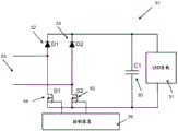
The retrofit LED tube 21 comprises an LED array 31 (indicated as LED load) for emitting light. The LED array 31 may include a plurality of LEDs connected in series and in parallel. Those skilled in the art will appreciate that in a practical embodiment, the LEDs are evenly distributed and spaced across the length of the tube 21 to provide as uniform illumination as possible through the LED tube 21 throughout the length of the LED tube. The present disclosure is not limited to any particular type of LED nor to LEDs of any color. Generally, white LEDs are used.
The LEDs are powered by a rectifier having an input and an output, wherein the rectifier is arranged to receive the AC supply voltage at its input 25, to convert the AC supply voltage to a DC voltage, and to provide the DC voltage at its output to the LED array 31.
The rectifiers shown in fig. 3 are four diodes indicated using reference numerals 24, 23, 26, 27. The rectifier is arranged to receive the AC supply voltage at its input 25. The main power supply arranged to provide this AC supply voltage is not part of the retrofit LED tube 1 and is not shown in fig. 3. The high frequency electronic ballast is also not depicted in fig. 3.
The operation principle of the rectifier is as follows.
During the positive part of the AC supply voltage, the rectifier diode 24, the rectifier diode 22, and the rectifier diode 27 are all in their positive direction, which means that current is flowing through the LED array 31 via a certain path.
During the negative part of the AC supply voltage, the rectifier diode 26, the rectifier diode 22, and the rectifier diode 23 are all in their positive direction, which means that current is flowing through the LED array 31 via a certain path.
One aspect of the invention is that a controllable switching circuit 29 is provided, which controllable switching circuit 29 is arranged to short-circuit the LED array 31 such that the LED array 31 does not emit light. Further, a control unit 28 is provided, which control unit 28 is arranged for wirelessly receiving a dimming command, and is arranged to control the controllable switching circuit 29 based on the received dimming command.
The above situation means that the LED tube 21 shown in fig. 3 can be disabled by switching on the controllable switching circuit 29. Thus, the LED array 31 is short-circuited, thereby preventing any light from being emitted while the current path is not interrupted. This is crucial when other tubes (e.g. LED tubes and/or fluorescent tubes) in the lighting system are connected in series to the LED tube 21 shown in fig. 3. All these lamps can still operate normally when the current path is not interrupted.
Step dimming is enabled in a multi-lamp luminaire lighting system using a controllable switching circuit 29 and a control unit 28. Step dimming is accomplished when at least one of the LED tubes (e.g., the LED tube shown in fig. 3) can be turned on or off while control thereof does not affect any of the other tubes in the lighting system. Thus, even when the LED tube shown in fig. 3 is turned off using the controllable switching circuit 29, the remaining ones of the tubes can still emit light.
Based on the above, the LED tube 21 may be controlled in such a way that, based on the received dimming command, the dimming command short-circuits the LED array 31 in case a dimming output level is required.
Thus, the control unit is arranged to short-circuit the LED array 31 using the controllable switching circuit 29 in case a certain dimming level is obtained, and to cancel the short-circuited LED array 31 in case no dimming level is obtained.
According to the invention, the short circuit provided by the controllable switching circuit is required to establish a current path through other fluorescent and LED tubes in the lighting system, since these tubes are all connected in series.
The control unit 28 is typically a microcontroller, microprocessor, field programmable gate array FPGA or the like. The control unit 28 may be equipped with a radio frequency receiver for receiving dimming commands from the dimmer switch. Alternatively, the control unit 28 may be equipped with a transceiver for transmitting data to a user device, a server, a dimmer switch, or the like. For example, the control unit 28 may transmit the actual dimming level to an "app" on the mobile phone via, for example, a WiFi connection for indicating the status of the dimming level to the user. In the present example, the control unit 28 is drawn as a single box. However, it is contemplated that the control unit comprises one or more integrated circuits, for example one integrated circuit relating to the RF part of the control unit and one integrated circuit relating to the control of the controllable switch circuit 29.
Further, the antenna may be comprised of a control unit 28 for increasing the wireless distance to the dimmer switch or router. To be able to wirelessly receive the input dimming level, the antenna may be an external (or internal) antenna. Common transmission techniques that may be used to wirelessly transmit dimming commands include: ZigBeeTM、BluetoothTMA WiFi-based protocol or any Mesh type (Mesh type) wireless network.
The present example is discussed in relation to an AC supply voltage of 230V, but may also operate with different kinds of AC supply voltages. Further, the present example is not limited to the particular rectifier or driver circuit shown in fig. 3. It should be clear to the skilled person that other types of rectifiers are equally suitable for energizing the LEDs in the LED array 31. It should also be noted that there are different kinds of dimming commands that actually short circuit the LED array 31, all of which are suitable for use in accordance with the present invention.
According to the present disclosure, a housing (not shown) for housing the retrofit LED tube 21 may be provided. More specifically, the housing may be arranged to house each of the components shown in fig. 3. For example, the housing may be a light-transmissive housing or a partially light-transmissive housing configured as a retrofit light tube type.
In this example, the control unit 28 is not powered by a separate battery, but is fed using AC supply power or using a storage capacitor 30.
A storage capacitor 30 is placed in parallel over the LED array 31. The LED tube 21 further comprises a further rectifier 22 having an input and an output, wherein said input of said further rectifier 22 is connected to said output of said power rectifier, and wherein said output of said further rectifier 22 is connected to said storage capacitor 30, wherein said further rectifier 22 is arranged to prevent depletion of said storage capacitor 30 when said controllable switching circuit short-circuits said LED array 31.
The above is an advantage in case the control unit 28 is enabled using the storage capacitor 30. The inventors have found that depletion of the storage capacitor should be prevented in order for the control unit 28 to function properly. In any case, the control unit 28 should be operable even when the LED array 31 is short-circuited. Once the user has provided the corresponding dimming command, the control unit 28 should be able to receive the dimming command and the short-circuit should be cancelled, (i.e. the controllable switch circuit 29 should be opened).
The control unit 28 may be equipped with a safety mechanism so that the storage capacitor 30 does not run out of energy, so that it will no longer be able to energize the control unit.
Then, the control unit 28 is arranged to determine that the voltage over the storage capacitor 30 is below a predetermined depletion threshold, and to temporarily control the controllable switching circuit 29 to not short-circuit the LED array 31 based on the determination that the voltage is below the predetermined depletion threshold, such that the storage capacitor can be charged.
Fig. 4 shows a circuit diagram 41 of another example of a retrofit light emitting diode, LED, lamp 41 according to the invention.
In the drawings, the same reference numerals denote the same components, or components performing the same or comparable functions or operations.
In the example shown in fig. 4, the mode of operation of the rectifier is different compared to the rectifier shown in fig. 3. The rectifier in fig. 4 consists of two rectifier diodes 42, 43 and two switches 44, 45. Two switches are also used, i.e. consisting of a controllable switching circuit that short-circuits the LED array 31.
During the positive part of the AC supply voltage the rectifying diode, indicated with reference numeral 42, is in forward mode, i.e. it is conducting. The switch, indicated with reference numeral 45, is opened so that current flows through the LED array 31. The rectifier diode, indicated with reference numeral 43, is in reverse mode so that it will not conduct any current. The switch, indicated with reference numeral 44, is closed, thereby ensuring that a current path through the LED array 31 is established during the positive part of the AC supply voltage.
During the negative part of the AC supply voltage the rectifying diode, indicated with reference numeral 43, is in forward mode, i.e. it is conducting. The switch indicated with reference numeral 44 is opened so that current flows through the LED array 31. The rectifier diode, indicated with reference numeral 42, is in reverse mode so that it will not conduct any current. The switch, indicated with reference numeral 45, is closed, thereby ensuring that a current path through the LED array 31 is established during the negative part of the AC supply voltage.
Two switches, indicated with reference numerals 44 and 45, can be controlled by the control unit according to the invention.
The control unit may be equipped with a synchronization circuit for detecting a transition of the AC supply voltage. That is, the synchronization circuit is able to detect the current state of the AC supply voltage, i.e. whether the voltage state is positive or negative. This information is used by the control unit to properly and timely control the switches indicated with reference numerals 44 and 45.
Typically, during normal operation, the switches indicated with reference numerals 44 and 45 are not closed and/or opened simultaneously. However, in case the user has indicated that a certain dimming level is to be obtained, using a dimming command, the control unit may decide to close the two switches indicated with reference numerals 44 and 45. This ensures that the LED array 31 is short-circuited. During the positive part of the AC supply voltage, a short circuit is obtained using a switch indicated with reference numeral 45, and during the negative part of the AC supply voltage, a short circuit is obtained using a switch indicated with reference numeral 44.
Fig. 5 shows a circuit diagram 51 of another example of a retrofit light emitting diode, LED, lamp tube 51 according to the invention.
Here, the two outputs of the two power rectifier diodes 52, 53 are connected to each other, wherein the inputs of the two power rectifier diodes are connected to a first connection of the input 52 of the power rectifier and a second connection of the input 52 of the power rectifier, respectively, and wherein the two controllable rectifier switches 54, 55 are connected to the LED array 31 on one side and to the first connection of the input 52 of the power rectifier, and to the second connection of the input 52 of the power rectifier, respectively, on the other side.
A control unit 56 is provided, which control unit 56 is arranged to control the two switches 54, 55 during normal operation, i.e. when the LED array 31 is supposed to emit light, and to use the switches 54, 55 to short-circuit the LED array 31 if necessary.
To short-circuit the LED array 31, the control unit will simultaneously close both switches 54, 55 to ensure that a direct low-ohmic current path is established between the two connections of the input 25. The advantage of this example is that losses in the rectifier diodes 52, 53 are prevented, since during a short circuit of the LED array 31 no current flows through any of these rectifier diodes 52, 53.
Any of the above mentioned switches may comprise a metal oxide semiconductor MOS, a field effect transistor FET, a relay or the like.
Fig. 6 shows a circuit diagram 61 of a further example of a retrofit light emitting diode, LED, lamp tube 61 according to the invention.
Here, a controllable switching circuit constituted by switches indicated with reference numerals 67 and 68 is included in the AC part of the LED tube 61. That is, the switches 67 and 68 are arranged to short circuit the inputs of a power rectifier, wherein the power rectifier comprises rectifying diodes indicated with reference numerals 62, 63, 64 and 65. A control unit 66 is provided to control the two switches 67 and 68.
Fig. 7 shows a simplified flowchart 71 illustrating one example of steps performed according to one embodiment of the present invention.
In a first step 72, an LED tube according to any one of the embodiments disclosed above is provided. That is, an LED tube is provided in a multi-lamp luminaire lighting system having at least two different lamps. At least one regular, known fluorescent lamp is provided in the lighting system, and at least one LED tube according to the invention is provided in the lighting system. At least some of the lamps are connected in series.
In a second step 73, the control unit wirelessly receives a dimming command, wherein the dimming command is a command to turn off (i.e. not to emit light by the LED array of LED tubes) the LED tubes.
The command may use the Zigbee protocol, WiFi protocol (like 802.1la/b/g or 802.1lac), Bluetooth protocol, or any protocol similar to such a protocol.
The dimming command may be received from a dimmer switch, but may also be received from a user device such as a tablet, smartphone, or the like. In the latter case, an "app" is provided on the smartphone for connection to the LED tube, more specifically to the control unit of the LED tube.
In a third step 74 the control unit controls the controllable switching circuit such that said LED array is short-circuited, so that the LED array does not emit light.
Other variations to the disclosed embodiments can be understood and effected by those skilled in the art in practicing the claimed invention, from a study of the drawings, the disclosure, and the appended claims. In the claims, the word "comprising" does not exclude other elements or steps, and the indefinite article "a" or "an" does not exclude a plurality. A single processor or other unit may fulfill the functions of several items recited in the claims. The mere fact that certain measures are recited in mutually different dependent claims does not indicate that a combination of these measures cannot be used to advantage. A computer program may be stored/distributed on a suitable medium, such as an optical storage medium or a solid-state medium supplied together with or as part of other hardware, but may also be distributed in other forms, such as via the internet or other wired or wireless telecommunication systems. Any reference signs in the claims shall not be construed as limiting the scope.
Claims (22)
1. A retrofit LED tube (16, 21) for a multi-lamp luminaire lighting system (11), the retrofit LED tube (16, 21, 41, 51, 61) being arranged to be powered by a single high frequency electronic ballast, the retrofit LED tube comprising:
-an LED array (31) for emitting light;
-a power rectifier having an input and an output, wherein the rectifier is arranged to receive, in use, an AC supply voltage at the input of the rectifier, to convert the AC supply voltage to a DC voltage, and to provide the DC voltage to the LED array via the output of the rectifier;
-a controllable switching circuit arranged to short-circuit the LED array such that the LED array does not emit light;
-a control unit (28) arranged for wirelessly receiving a dimming command and for controlling the controllable switching circuit based on the received dimming command;
-a storage capacitor placed in parallel over the LED array;
-a further rectifier (22) having an input and an output, wherein the input of the further rectifier is connected to the output of the power rectifier, and wherein the output of the further rectifier is connected to the storage capacitor, wherein the storage capacitor is arranged to prevent depletion of the storage capacitor when the controllable switching circuit shorts the LED array, wherein the control unit is energized via the storage capacitor, wherein the control unit is further arranged to:
1) determining that a voltage across the storage capacitor is below a predetermined depletion threshold;
2) based on the determination that the voltage is below a predetermined depletion threshold, temporarily controlling the controllable switching circuit not to short the LED array such that the storage capacitor can be charged.
2. The retrofit LED tube according to claim 1, wherein the controllable switch circuit (29) is arranged between the power rectifier (D1-D4) and the LED array such that the controllable switch circuit (29) is arranged to short-circuit the output of the power rectifier.
3. The retrofit LED tube according to claim 1, wherein the power rectifier comprises two power rectifier diodes (D1 and D2) and two controllable power rectifier switches (S1 and S2), wherein the controllable switch circuit is formed by the two controllable power rectifier switches, wherein the two controllable power rectifier switches are arranged to short circuit the LED array when both controllable power rectifier switches are closed.
4. The retrofit LED tube according to claim 3, wherein an input of one of said two power rectifier diodes (D1) is connected to a first connection of said inputs of said power rectifier and an output is connected to said LED array;
the other of the two power rectifier diodes (D2) having its input connected to the LED array and its output connected to the first connection of the input of the power rectifier;
one of the two controllable power rectifier switches (S1) is connected to a second connection of the inputs of the power rectifier and an output is connected to the LED array; and
the other of the two controllable power rectifier switches (S2) is connected to the LED array and an output is connected to a second connection of the input of the power rectifier.
5. The retrofit LED tube of any of claims 1-2, wherein any of said switches comprises: metal oxide semiconductor MOS, field effect transistor FET.
6. The retrofit LED tube of any of claims 1-2, wherein the controllable switch circuit comprises a relay.
7. The retrofit LED tube according to any of the claims 1-2, wherein the control unit is arranged to perform step 2) for a predetermined amount of time.
8. The retrofit LED tube according to claim 7, wherein the control unit is arranged to perform step 2) until the voltage is above a predetermined stored threshold.
9. A retrofit LED tube for a multi-lamp luminaire lighting system (11), the retrofit LED tube arranged to be powered by a single high frequency electronic ballast, the retrofit LED tube comprising:
-an LED array (31) for emitting light;
-a power rectifier having an input and an output, wherein the rectifier is arranged to receive, in use, an AC supply voltage at the input of the rectifier, to convert the AC supply voltage to a DC voltage, and to provide the DC voltage to the LED array via the output of the rectifier;
-a controllable switching circuit arranged to short-circuit the LED array such that the LED array does not emit light;
-a control unit arranged for wirelessly receiving a dimming command and for controlling the controllable switching circuit based on the received dimming command;
-a storage capacitor placed in parallel over the LED array;
wherein the storage capacitor is arranged to prevent depletion of the storage capacitor when the controllable switching circuit shorts the LED array, wherein the control unit is energized via the storage capacitor, wherein the control unit is further arranged to:
1) determining that a voltage across the storage capacitor is below a predetermined depletion threshold;
2) based on the determination that the voltage is below a predetermined depletion threshold, temporarily controlling the controllable switching circuit not to short the LED array such that the storage capacitor can be charged;
wherein the power rectifier comprises two power rectifier diodes and two controllable power rectifier switches, wherein the controllable switch circuit is formed by the two controllable power rectifier switches, wherein the two controllable power rectifier switches are arranged to short circuit the LED array when both the two controllable power rectifier switches are closed.
10. The retrofit LED tube according to claim 9, wherein two outputs of the two power rectifier diodes are connected to each other, wherein inputs of the two power rectifier diodes are connected to a first connection of the inputs of the power rectifier and to a second connection of the inputs of the power rectifier, respectively, and wherein the two controllable rectifier switches are connected to the LED array on one side and to the first connection of the inputs of the power rectifier and to the second connection of the inputs of the power rectifier, respectively, on the other side.
11. The retrofit LED tube of any of claims 9-10, wherein any of the switches comprises: metal oxide semiconductor MOS, field effect transistor FET.
12. The retrofit LED tube of any of claims 9-10, wherein the controllable switch circuit comprises a relay.
13. The retrofit LED tube according to any of the claims 9-10, wherein the control unit is arranged to perform step 2) for a predetermined amount of time.
14. The retrofit LED tube according to claim 13, wherein the control unit is arranged to perform step 2) until the voltage is above a predetermined stored threshold.
15. A retrofit LED tube for a multi-lamp luminaire lighting system (11), the retrofit LED tube arranged to be powered by a single high frequency electronic ballast, the retrofit LED tube comprising:
-an LED array (31) for emitting light;
-a power rectifier having an input and an output, wherein the rectifier is arranged to receive, in use, an AC supply voltage at the input of the rectifier, to convert the AC supply voltage to a DC voltage, and to provide the DC voltage to the LED array via the output of the rectifier;
-a controllable switching circuit arranged to short-circuit the LED array such that the LED array does not emit light;
-a control unit arranged for wirelessly receiving a dimming command and for controlling the controllable switching circuit based on the received dimming command;
-a storage capacitor placed in parallel over the LED array;
wherein the storage capacitor is arranged to prevent depletion of the storage capacitor when the controllable switching circuit shorts the LED array, wherein the control unit is energized via the storage capacitor, wherein the control unit is further arranged to:
1) determining that a voltage across the storage capacitor is below a predetermined depletion threshold;
2) based on the determination that the voltage is below a predetermined depletion threshold, temporarily controlling the controllable switching circuit not to short the LED array such that the storage capacitor can be charged;
wherein the controllable switching circuit is arranged at the input of the power rectifier such that the LED array is short-circuited by short-circuiting the AC supply voltage at the input of the power rectifier.
16. The retrofit LED tube of claim 15, wherein any of the switches comprises: metal oxide semiconductor MOS, field effect transistor FET.
17. The retrofit LED tube of claim 15, wherein the controllable switch circuit comprises a relay.
18. The retrofit LED tube of claim 15, wherein the control unit is arranged to perform step 2) for a predetermined amount of time.
19. The retrofit LED tube according to claim 15, wherein the control unit is arranged to perform step 2) until the voltage is above a predetermined stored threshold.
20. A lighting system (11) of a multi-lamp luminaire, comprising:
-a high frequency electronic ballast (12),
-at least one fluorescent tube (15), and
-at least one retrofit LED tube according to any of the preceding claims, wherein said at least one retrofit LED tube and said at least one fluorescent tube are connected in series.
21. The lighting system of a multi-lamp luminaire of claim 20, further comprising:
-a dimmer switch arranged for setting a dimming command by a user and arranged for wirelessly transmitting the dimming command to the control unit consisting of the at least one retrofit LED tube.
22. A method (71) of operating a retrofit LED tube according to any of the claims 1 to 19, wherein the method comprises the steps of:
-wirelessly receiving (73), by the control unit, a dimming command, the dimming command being a command not to emit light by the LED array;
-controlling (74), by the control unit, the controllable switching circuit such that the LED array is short-circuited, whereby the LED array does not emit light.
Applications Claiming Priority (3)
| Application Number | Priority Date | Filing Date | Title |
|---|---|---|---|
| EP16190215 | 2016-09-22 | ||
| EP16190215.0 | 2016-09-22 | ||
| PCT/EP2017/073482 WO2018054841A1 (en) | 2016-09-22 | 2017-09-18 | A retrofit light emitting diode, led, tube for enabling step dimming in a multi lamp luminaire lighting system |
Publications (2)
| Publication Number | Publication Date |
|---|---|
| CN109792819A CN109792819A (en) | 2019-05-21 |
| CN109792819B true CN109792819B (en) | 2021-09-28 |
Family
ID=56985550
Family Applications (1)
| Application Number | Title | Priority Date | Filing Date |
|---|---|---|---|
| CN201780058257.4A Active CN109792819B (en) | 2016-09-22 | 2017-09-18 | Modified light-emitting diode (LED) lamp tube for realizing step-by-step dimming in multi-lamp lighting system |
Country Status (5)
| Country | Link |
|---|---|
| US (1) | US10638564B2 (en) |
| EP (1) | EP3516930B1 (en) |
| JP (1) | JP6994503B2 (en) |
| CN (1) | CN109792819B (en) |
| WO (1) | WO2018054841A1 (en) |
Families Citing this family (5)
| Publication number | Priority date | Publication date | Assignee | Title |
|---|---|---|---|---|
| JP6994503B2 (en) * | 2016-09-22 | 2022-01-14 | シグニファイ ホールディング ビー ヴィ | Multi-lamp lighting fixtures Retrofit light emitting diode (LED) tubes to enable step dimming in lighting systems |
| US11229101B2 (en) | 2018-07-03 | 2022-01-18 | Signify Holding B.V. | LED driver and LED lighting system for use with a high frequency electronic ballast |
| EP3595412B1 (en) * | 2018-07-13 | 2024-03-06 | Signify Holding B.V. | Led replacement lamp compatible with a ballast of a high-pressure sodium lamp and a ballast of a mercury vapor lamp |
| US11259381B2 (en) | 2018-08-17 | 2022-02-22 | Signify Holding B.V. | LED driver and LED lighting system for use with a high frequency electronic ballast |
| TWI747550B (en) * | 2020-10-12 | 2021-11-21 | 友達光電股份有限公司 | Pixel circuit and display device |
Citations (5)
| Publication number | Priority date | Publication date | Assignee | Title |
|---|---|---|---|---|
| WO2007066252A1 (en) * | 2005-12-09 | 2007-06-14 | Koninklijke Philips Electronics N.V. | Method for driving a hybrid lamp and a hybrid lamp assembly |
| CN103181241A (en) * | 2010-10-19 | 2013-06-26 | 皇家飞利浦电子股份有限公司 | Led retrofit lamp |
| EP2922369A1 (en) * | 2014-03-18 | 2015-09-23 | Laurence P. Sadwick | Fluorescent lamp LED replacement |
| CN105612814A (en) * | 2013-09-25 | 2016-05-25 | 硅山有限公司 | Led lighting system |
| WO2016145264A1 (en) * | 2015-03-10 | 2016-09-15 | Innosys, Inc. | Solid state fluorescent lamp and high intensity discharge replacement |
Family Cites Families (10)
| Publication number | Priority date | Publication date | Assignee | Title |
|---|---|---|---|---|
| US7978485B2 (en) * | 2007-05-04 | 2011-07-12 | Stmicroelectronics, Inc. | Thyristor power control circuit with damping circuit maintaining thyristor holding current |
| WO2009004563A1 (en) * | 2007-07-02 | 2009-01-08 | Philips Intellectual Property & Standards Gmbh | Driver device for a load and method of driving a load with such a driver device |
| US8581501B2 (en) | 2009-08-18 | 2013-11-12 | General Electric Company | Fluorescent dimming ballast with improved efficiency |
| CN104255084B (en) | 2011-12-05 | 2016-04-27 | 通用电气公司 | For the step light regulating method of lamp ballast |
| US9618185B2 (en) * | 2012-03-08 | 2017-04-11 | Flextronics Ap, Llc | LED array for replacing flourescent tubes |
| WO2013150399A1 (en) * | 2012-03-20 | 2013-10-10 | Koninklijke Philips N.V. | Led string driver circuit including a charge control diode for a capacitor |
| WO2014009836A2 (en) * | 2012-07-11 | 2014-01-16 | Koninklijke Philips N.V. | Driver circuit between fluorescent ballast and led |
| US9769890B1 (en) * | 2015-08-10 | 2017-09-19 | Universal Lighting Technologies, Inc. | Circuit and method for eliminating power-off flash for LED drivers |
| JP6994503B2 (en) * | 2016-09-22 | 2022-01-14 | シグニファイ ホールディング ビー ヴィ | Multi-lamp lighting fixtures Retrofit light emitting diode (LED) tubes to enable step dimming in lighting systems |
| CA3076810C (en) * | 2017-09-22 | 2023-08-22 | Lutron Technology Company Llc | Load control device having a wide output range |
-
2017
- 2017-09-18 JP JP2019515453A patent/JP6994503B2/en active Active
- 2017-09-18 US US16/329,804 patent/US10638564B2/en active Active
- 2017-09-18 CN CN201780058257.4A patent/CN109792819B/en active Active
- 2017-09-18 WO PCT/EP2017/073482 patent/WO2018054841A1/en unknown
- 2017-09-18 EP EP17776963.5A patent/EP3516930B1/en active Active
Patent Citations (5)
| Publication number | Priority date | Publication date | Assignee | Title |
|---|---|---|---|---|
| WO2007066252A1 (en) * | 2005-12-09 | 2007-06-14 | Koninklijke Philips Electronics N.V. | Method for driving a hybrid lamp and a hybrid lamp assembly |
| CN103181241A (en) * | 2010-10-19 | 2013-06-26 | 皇家飞利浦电子股份有限公司 | Led retrofit lamp |
| CN105612814A (en) * | 2013-09-25 | 2016-05-25 | 硅山有限公司 | Led lighting system |
| EP2922369A1 (en) * | 2014-03-18 | 2015-09-23 | Laurence P. Sadwick | Fluorescent lamp LED replacement |
| WO2016145264A1 (en) * | 2015-03-10 | 2016-09-15 | Innosys, Inc. | Solid state fluorescent lamp and high intensity discharge replacement |
Also Published As
| Publication number | Publication date |
|---|---|
| EP3516930B1 (en) | 2020-01-29 |
| US20190208593A1 (en) | 2019-07-04 |
| CN109792819A (en) | 2019-05-21 |
| US10638564B2 (en) | 2020-04-28 |
| JP6994503B2 (en) | 2022-01-14 |
| EP3516930A1 (en) | 2019-07-31 |
| JP2019530163A (en) | 2019-10-17 |
| WO2018054841A1 (en) | 2018-03-29 |
Similar Documents
| Publication | Publication Date | Title |
|---|---|---|
| CN109792819B (en) | Modified light-emitting diode (LED) lamp tube for realizing step-by-step dimming in multi-lamp lighting system | |
| JP6258951B2 (en) | Circuit device and LED lamp provided with circuit device | |
| TWI437915B (en) | Led drive circuit, led illumination fixture, led illumination device, and led illumination system | |
| JP4943402B2 (en) | LED drive circuit, LED illumination lamp, LED illumination device, and LED illumination system | |
| JP5214585B2 (en) | LED drive circuit, phase control dimmer, LED illumination lamp, LED illumination device, and LED illumination system | |
| TWI387396B (en) | Dimmable led lamp and dimmable led lighting apparatus | |
| US20140312796A1 (en) | Circuit arrangement for operating a low-power lighting unit and method of operating the same | |
| WO2013001756A1 (en) | Led illumination circuit and led illumination device | |
| US9801246B2 (en) | Dimmable LED light | |
| KR20120034150A (en) | Dc power source unit and led lamp system | |
| US8853963B2 (en) | Low current solution for illuminated switches using DC operated LEDs | |
| CN110547047B (en) | Retrofit Light Emitting Diode (LED) lamp for reducing audible noise from high frequency electronic ballast | |
| KR20130119081A (en) | Led lighting apparatus | |
| US11172551B2 (en) | Solid-state lighting with a driver controllable by a power-line dimmer | |
| KR101844460B1 (en) | LED lamp control circuit compatible type fluorescent and lighting the use | |
| KR102231567B1 (en) | Dimming control apparatus of lamp | |
| CN112369125B (en) | LED driver and LED lighting system for use with high frequency electronic ballasts | |
| KR101052338B1 (en) | Power supply circuit for led lamp with fluorescent lamp type | |
| JP5376867B2 (en) | Illumination lighting device, luminaire, and illumination system | |
| US11490476B2 (en) | Solid-state lighting with a luminaire dimming driver | |
| KR101139344B1 (en) | Led drive circuit, led illumination fixture, led illumination device, and led illumination system | |
| JP2006100129A (en) | Illumination device |
Legal Events
| Date | Code | Title | Description |
|---|---|---|---|
| PB01 | Publication | ||
| PB01 | Publication | ||
| SE01 | Entry into force of request for substantive examination | ||
| SE01 | Entry into force of request for substantive examination | ||
| GR01 | Patent grant | ||
| GR01 | Patent grant |