CN109791724B - Toilet system, toilet management method, and storage medium - Google Patents
Toilet system, toilet management method, and storage medium Download PDFInfo
- Publication number
- CN109791724B CN109791724B CN201780061515.4A CN201780061515A CN109791724B CN 109791724 B CN109791724 B CN 109791724B CN 201780061515 A CN201780061515 A CN 201780061515A CN 109791724 B CN109791724 B CN 109791724B
- Authority
- CN
- China
- Prior art keywords
- toilet
- door
- abnormality
- user
- compartment
- Prior art date
- Legal status (The legal status is an assumption and is not a legal conclusion. Google has not performed a legal analysis and makes no representation as to the accuracy of the status listed.)
- Active
Links
Images


Classifications
-
- G—PHYSICS
- G08—SIGNALLING
- G08B—SIGNALLING OR CALLING SYSTEMS; ORDER TELEGRAPHS; ALARM SYSTEMS
- G08B13/00—Burglar, theft or intruder alarms
- G08B13/18—Actuation by interference with heat, light, or radiation of shorter wavelength; Actuation by intruding sources of heat, light, or radiation of shorter wavelength
- G08B13/189—Actuation by interference with heat, light, or radiation of shorter wavelength; Actuation by intruding sources of heat, light, or radiation of shorter wavelength using passive radiation detection systems
- G08B13/194—Actuation by interference with heat, light, or radiation of shorter wavelength; Actuation by intruding sources of heat, light, or radiation of shorter wavelength using passive radiation detection systems using image scanning and comparing systems
- G08B13/196—Actuation by interference with heat, light, or radiation of shorter wavelength; Actuation by intruding sources of heat, light, or radiation of shorter wavelength using passive radiation detection systems using image scanning and comparing systems using television cameras
- G08B13/19602—Image analysis to detect motion of the intruder, e.g. by frame subtraction
-
- G—PHYSICS
- G05—CONTROLLING; REGULATING
- G05B—CONTROL OR REGULATING SYSTEMS IN GENERAL; FUNCTIONAL ELEMENTS OF SUCH SYSTEMS; MONITORING OR TESTING ARRANGEMENTS FOR SUCH SYSTEMS OR ELEMENTS
- G05B19/00—Programme-control systems
- G05B19/02—Programme-control systems electric
- G05B19/18—Numerical control [NC], i.e. automatically operating machines, in particular machine tools, e.g. in a manufacturing environment, so as to execute positioning, movement or co-ordinated operations by means of programme data in numerical form
- G05B19/4155—Numerical control [NC], i.e. automatically operating machines, in particular machine tools, e.g. in a manufacturing environment, so as to execute positioning, movement or co-ordinated operations by means of programme data in numerical form characterised by programme execution, i.e. part programme or machine function execution, e.g. selection of a programme
-
- A—HUMAN NECESSITIES
- A47—FURNITURE; DOMESTIC ARTICLES OR APPLIANCES; COFFEE MILLS; SPICE MILLS; SUCTION CLEANERS IN GENERAL
- A47K—SANITARY EQUIPMENT NOT OTHERWISE PROVIDED FOR; TOILET ACCESSORIES
- A47K17/00—Other equipment, e.g. separate apparatus for deodorising, disinfecting or cleaning devices without flushing for toilet bowls, seats or covers; Holders for toilet brushes
-
- E—FIXED CONSTRUCTIONS
- E03—WATER SUPPLY; SEWERAGE
- E03D—WATER-CLOSETS OR URINALS WITH FLUSHING DEVICES; FLUSHING VALVES THEREFOR
- E03D11/00—Other component parts of water-closets, e.g. noise-reducing means in the flushing system, flushing pipes mounted in the bowl, seals for the bowl outlet, devices preventing overflow of the bowl contents; devices forming a water seal in the bowl after flushing, devices eliminating obstructions in the bowl outlet or preventing backflow of water and excrements from the waterpipe
-
- G—PHYSICS
- G08—SIGNALLING
- G08B—SIGNALLING OR CALLING SYSTEMS; ORDER TELEGRAPHS; ALARM SYSTEMS
- G08B21/00—Alarms responsive to a single specified undesired or abnormal condition and not otherwise provided for
- G08B21/02—Alarms for ensuring the safety of persons
- G08B21/04—Alarms for ensuring the safety of persons responsive to non-activity, e.g. of elderly persons
- G08B21/0407—Alarms for ensuring the safety of persons responsive to non-activity, e.g. of elderly persons based on behaviour analysis
- G08B21/043—Alarms for ensuring the safety of persons responsive to non-activity, e.g. of elderly persons based on behaviour analysis detecting an emergency event, e.g. a fall
-
- G—PHYSICS
- G08—SIGNALLING
- G08B—SIGNALLING OR CALLING SYSTEMS; ORDER TELEGRAPHS; ALARM SYSTEMS
- G08B21/00—Alarms responsive to a single specified undesired or abnormal condition and not otherwise provided for
- G08B21/02—Alarms for ensuring the safety of persons
- G08B21/04—Alarms for ensuring the safety of persons responsive to non-activity, e.g. of elderly persons
- G08B21/0438—Sensor means for detecting
- G08B21/0492—Sensor dual technology, i.e. two or more technologies collaborate to extract unsafe condition, e.g. video tracking and RFID tracking
-
- G—PHYSICS
- G05—CONTROLLING; REGULATING
- G05B—CONTROL OR REGULATING SYSTEMS IN GENERAL; FUNCTIONAL ELEMENTS OF SUCH SYSTEMS; MONITORING OR TESTING ARRANGEMENTS FOR SUCH SYSTEMS OR ELEMENTS
- G05B2219/00—Program-control systems
- G05B2219/30—Nc systems
- G05B2219/40—Robotics, robotics mapping to robotics vision
- G05B2219/40062—Door opening
Landscapes
- Health & Medical Sciences (AREA)
- Engineering & Computer Science (AREA)
- Physics & Mathematics (AREA)
- General Physics & Mathematics (AREA)
- Public Health (AREA)
- General Health & Medical Sciences (AREA)
- Gerontology & Geriatric Medicine (AREA)
- Business, Economics & Management (AREA)
- Emergency Management (AREA)
- Human Computer Interaction (AREA)
- Manufacturing & Machinery (AREA)
- Automation & Control Theory (AREA)
- Life Sciences & Earth Sciences (AREA)
- Hydrology & Water Resources (AREA)
- Water Supply & Treatment (AREA)
- Psychiatry (AREA)
- Computer Vision & Pattern Recognition (AREA)
- Epidemiology (AREA)
- Multimedia (AREA)
- Social Psychology (AREA)
- Psychology (AREA)
- Sanitary Device For Flush Toilet (AREA)
- Alarm Systems (AREA)
- Toilet Supplies (AREA)
- Emergency Alarm Devices (AREA)
Abstract
Provided is a technology for controlling a toilet door according to the state in a toilet compartment when an abnormality occurs. The toilet system of the present invention includes: a detection part for detecting the state in the toilet compartment; an abnormality determination unit that determines the occurrence and type of an abnormality based on the detection result of the detection unit; and a door control unit that controls opening and closing of the door according to the type of the abnormality when it is determined that the abnormality has occurred.
Description
Technical Field
The present invention relates to a toilet system, a toilet management method, and a toilet management program.
Background
Conventionally, the following systems have been proposed: that is, if the user of the toilet stays in the toilet for a long time, for example, 30 minutes or more, it is determined that there is a fear of physical discomfort or an illegal intruder, and an alarm is issued.
(Prior art document)
(patent document)
Patent document 1: japanese laid-open patent publication No. 2007-58406
Patent document 2: japanese patent laid-open publication No. 2007-241446
Patent document 3: japanese patent No. 4991771
Disclosure of Invention
(problems to be solved by the invention)
In the conventional system, an alarm is issued similarly in the case where the user is uncomfortable, and in the case where the user is an unauthorized intruder. Therefore, the manager who goes to the toilet in response to the alarm knows the situation after arriving at the toilet, opens the door to rescue the user in the toilet when the user is uncomfortable, and takes measures to control the intruder according to the situation when the intruder is illegal.
In this case, in a situation where the user cannot move due to physical discomfort, the door of the toilet compartment is often locked, which may hinder quick rescue.
On the other hand, in the case of an illegal intruder, it is preferable to lock the door of the toilet room until the manager arrives in order to control the intruder.
Accordingly, an object of the present invention is to provide a technique for controlling a door of a toilet compartment according to a situation in the toilet compartment when an abnormality occurs.
(measures taken to solve the problems)
In order to solve the above problem, a toilet system according to the present invention includes: a detection unit for detecting a state in the toilet compartment; an abnormality determination unit that determines the occurrence and type of an abnormality based on the detection result of the detection unit; and a door control unit that controls opening and closing of the door according to the type of the abnormality when it is determined that the abnormality has occurred.
Accordingly, the toilet system of the present invention can control the door of the toilet compartment according to the condition of the toilet compartment when an abnormality occurs.
In order to solve the above problem, the detection unit of the toilet system according to the present invention detects a state of a user in the toilet compartment based on at least one of a position, a movement, or a shape of an object in the toilet compartment, and when the state of the user satisfies a predetermined first condition, the abnormality determination unit determines that an abnormality has occurred, and the door control unit performs control to open the door.
Accordingly, the door can be controlled to be opened in a situation where an abnormality occurs and a user in the toilet compartment wants to be rescued quickly.
The first condition of the toilet system is a case where a maximum value of the height of the user detected by the detection unit is equal to or less than a predetermined lower limit value, or a case where the user is stationary for a predetermined time or longer.
Accordingly, the control of opening the door can be performed quickly in a situation where the user falls down in the toilet compartment.
The detection unit of the toilet system detects a state of a user in the toilet compartment based on at least one of a position, a movement, or a shape of an object in the toilet compartment, and when the state of the user satisfies a predetermined second condition, the abnormality determination unit determines that an abnormality has occurred, and the door control unit maintains the state in which the door is closed.
Accordingly, in a situation where an abnormality occurs and the user wants to stay in the toilet compartment, the control for maintaining the door closed state can be performed.
The second condition of the toilet system is that the second condition exceeds a predetermined upper limit value, and the second condition is that the user is present, that the user changes the shape of the equipment installed in the toilet compartment, or that the user performs a specific operation on the toilet equipment.
Accordingly, when the user performs the candid photograph or breaks the toilet equipment, the door can be controlled to be kept closed in order to stay in the toilet.
The detection unit of the toilet system detects entry/exit of a user into/from the toilet compartment, compares the toilet compartment before the user enters and the toilet compartment after the user exits, and determines that an abnormality has occurred when an object that is not present in the toilet compartment before the user enters is present in the toilet compartment after the user exits, and the door control unit controls the door to close the door.
Accordingly, when there is a remnant in the toilet compartment, the door can be controlled to be closed.
In order to solve the above problem, a computer executes the following steps of the toilet management method of the present invention: a detection step of detecting a state in the toilet compartment; an abnormality determination step of determining the occurrence and type of an abnormality based on a detection result of the detection step; and a door control step of controlling opening and closing of the door in accordance with a type of the abnormality when it is determined that the abnormality has occurred.
Accordingly, in a situation where an abnormality occurs and a user in the toilet compartment wants to be promptly rescued, the door can be controlled to be opened.
The first condition of the toilet management method is that the maximum height of the user detected by the detection unit is equal to or less than a predetermined lower limit value, or that the user is stationary for a predetermined time or longer.
The detection unit of the toilet management method detects a state of a user in the toilet compartment based on at least one of a position, a movement, or a shape of an object in the toilet compartment, and when the state of the user satisfies a predetermined second condition, the abnormality determination unit determines that an abnormality has occurred, and the door control unit maintains the state of the door closed.
The second condition of the toilet management method is that the user is present beyond a predetermined upper limit value, that the user changes the shape of the toilet equipment installed in the toilet, or that the user performs a specific operation on the toilet equipment.
The detection unit of the toilet management method detects entry/exit of a user into/from the toilet compartment, compares the toilet compartment before the user enters and the toilet compartment after the user exits, determines that an abnormality has occurred when an object that is not present in the toilet compartment before the user enters is present in the toilet compartment after the user exits, and controls the door control unit to close the door.
Further, the toilet management program of the present invention causes a computer to execute the above toilet management method.
(Effect of the invention)
According to the present invention, it is possible to provide a technique for controlling a door of a toilet compartment in accordance with a situation in the toilet compartment when an abnormality occurs.
Drawings
Fig. 1 is a diagram showing the overall structure of a toilet system.
Fig. 2 is a diagram showing an example of a toilet facility.
Fig. 3 is a perspective view showing a toilet compartment.
Fig. 4 is a plan view showing a toilet compartment.
Fig. 5 is a front view showing a toilet compartment.
Fig. 6 is a view of a toilet compartment showing the door as a hinged door.
Fig. 7 is a view of a toilet compartment showing the door as a sliding door.
Fig. 8 is a diagram showing an example of the controller.
Fig. 9 is a diagram showing the configuration of the control device.
Fig. 10 is a diagram showing the configuration of the management server.
Fig. 11 is an explanatory view of a toilet management method.
Fig. 12 is an explanatory view of a toilet management method.
Detailed Description
(embodiment mode 1)
Hereinafter, embodiments of the present invention will be described with reference to the drawings. The embodiment is an example of the present invention, and the configuration of the present invention is not limited to the following example.
Fig. 1 is a diagram showing the overall configuration of a toilet system according to embodiment 1. The toilet system 100 of the present embodiment includes a toilet facility 10 and a management server 2, which are connected to each other via a network 5 such as the internet. In the toilet system 100, the toilet facility 1 detects a state in the toilet room 14 installed in the toilet facility 10 and notifies the management server 2, and the management server 2 transmits an alarm to the manager terminal 3 or the like and controls the door of the toilet room 14 when determining that the user stays in the toilet room 14 for a predetermined time or longer. Although fig. 1 shows an example in which the toilet system 100 does not include the manager terminal 3, the toilet system 100 may include the manager terminal 3.
The toilet facility 10 is a toilet used by the public in commercial facilities such as department stores and stations. The toilet facility 10 is provided on each of a plurality of buildings and each of a plurality of floors of the buildings, for example. The toilet facility 10 detects the state in the toilet room by the control device 44 provided in the toilet room 14, and periodically transmits the state as the use information to the management server 2.
The management server 2 receives the use information from the toilet facility 1, and performs a process of outputting a preliminary warning to a user in the toilet room 14 and a process of sending an alarm to a manager based on the use information.
Fig. 2 is a view showing an example of the toilet facility 10, fig. 3 is a perspective view showing the toilet compartment 14 provided in the toilet facility 10, fig. 4 is a plan view showing the toilet compartment 14, fig. 5 is a front view showing the toilet compartment, fig. 6 is a view showing the toilet compartment 14 in which the door 9 is a hinged door, and fig. 7 is a view showing the toilet compartment 14 in which the door 9 is a sliding door.
As shown in fig. 2, the toilet facilities 10 are divided into, for example, a female toilet facility 101, a male toilet facility 102, and a multi-function toilet facility 103. The female toilet facility 101 and the male toilet facility 102 are provided with a plurality of toilet compartments 14. Fig. 2 shows an example in which the multi-function toilet facility 103 is constituted by one toilet compartment 14, but the multi-function toilet facility 103 may have a plurality of toilet compartments 14. Here, the toilet compartment 14 is a space surrounded by doors and walls and provided with the toilet facility 1 which is usually used by only one person. The toilet compartment 14 is not limited to one person, and a caregiver or an infant may enter the toilet compartment together with the user.
The toilet compartment 14 has: a pair of left and right side walls 14L and 14R and a rear wall 14B surrounding the three sides, and a door 9 for opening and closing the doorway 4 of the toilet compartment 14. A toilet 41 is provided in a toilet compartment 14 whose four sides are surrounded by side walls 14L, 14R, a rear wall 14B, and a door 9. The walls 14L, 14R, 14B and the door 9 surrounding the toilet compartment 14 may be provided at a height from the floor 14F to the ceiling 14C, but in the present embodiment, as shown in fig. 5, spaces are provided between the left and right side walls 14L, 14R and the door 9 and the ceiling 14C to allow air to flow therethrough.
Here, the left and right sides mean the left and right sides when facing the doorway 4 from the outside of the toilet, the front and back sides mean the front and back when sitting on the toilet, and the up and down sides mean the ceiling 14C side and the installation surface (floor) 14F side of the toilet 41.
The left and right side walls 14L, 14R are made of a plate material (see fig. 2, 3) having one end side in a straight line shape and the other end side in a curved shape (a quadratic surface), and are formed in a J-shape in cross section (horizontal section), and when there is an adjacent toilet compartment 14, the left side wall 14L doubles as a right side wall 14R of another toilet compartment 14 adjacent to the left side of the toilet compartment 14, and the right side wall 14R doubles as a left side wall 14L of another toilet compartment 14 adjacent to the right side of the toilet compartment 14.
The right side wall 14R is provided with a guide rail 8 (see fig. 3) at an inner upper portion thereof. The guide rail 8 having one end held by the right side wall 14R is fixedly provided at the left side wall 14L via the upper portion of the doorway 4 and the other end. Although not shown in fig. 3, the guide rail 8 is also provided inside the toilet compartment, which is also the left side wall 14L serving as the right side wall of the toilet compartment 14 adjacent to the left side. Further, a door drive unit 63 is provided near the guide rail 8 at the upper portion of the front end of the right side wall 14R. The door 9 is provided in a suspended state on the guide rail 8, and the door 9 moves along the guide rail 8 by the door driving unit 63 to open and close the doorway 4. Further, a lock 91 is provided on the guide rail 8, and locking/unlocking of the lock 91 is controlled by the door driving unit 63 in accordance with driving of the door 9.
An inner face of the left side end portion of the door 9 is provided with an operation panel 61 having an opening and closing button of the door 9 and electrically connected to the door driving unit 63. When the close button of the operation panel 61 is pressed by the user's operation, the door drive unit 63 drives the door 9 to close, and the lock 91 engages with the door 9 and is locked in a state where the left end of the door 9 abuts on the left side wall 14L, thereby preventing the door from being opened. When the open button of the operation panel 61 is pressed, the door driving unit 63 drives the lock 91 to release the engagement with the door 9, thereby unlocking the door and driving the door 9 in the opening direction. The lock 91 is not limited to a structure provided on the guide rail 8 and engaged with the door 9, and may be a structure provided on the left side wall 14L, the right side wall 14R, the floor 14F, or the like and engaged with the door 9 to suppress the door from being opened. Conversely, the door 9 may be configured to engage with the guide rail 8, the left side wall 14L, the right side wall 14R, the floor 14F, and the like to suppress the door from being opened. In this example, although the door 9 is locked by the lock 91 so that the door 9 is not opened after the door 9 is closed, the lock 91 may be omitted as long as the door 9 is not easily opened from the outside of the closed door 9, for example, the door 9 does not rotate even if the gear of the door driving unit 63 is manually opened by applying a force by another person.
In addition, although fig. 3 to 5 show an example of a toilet room using a rotatable door 9, the present invention is not limited to this, and a configuration in which the door 9 is a hinged door as shown in fig. 6 or a configuration in which the door 9 is a sliding door as shown in fig. 7 may be used.
The toilet compartment 14 shown in fig. 6 is surrounded on three sides by a pair of left and right side walls 14L, 14R and a rear wall 14B, a left front wall 141L is provided on the left side of the front surface, a right front wall 141R is provided on the right side of the front surface, and an opening between the left front wall 141L and the right front wall 141R serves as the entrance 4. The door 9 is swingably attached to the left end of the right front wall 141R via a hinge (not shown). A door drive unit 63 is provided at the upper part of the door 9 on the hinge side, and the door 9 is opened and closed by the drive of the door drive unit 63. For example, the door driving unit 63 rotates the door end (one side end opposite to the hinge) 9A of the door 9 inward about the hinge as a center axis to open the doorway, and conversely rotates the door end 9A until the right end of the left front wall 141L stops to close the doorway.
An operation panel 61 for operating opening and closing by the door drive unit 63 is provided on the inner side of the left front wall 141L.
An upper frame 142 is provided at the upper ends of the left front wall 141L and the right front wall 141R, and the lock 91 is provided on the upper frame 142. When the door 9 is closed by the door driving unit 63 driving the lock 91 in association with the opening and closing of the door 9, the door 9 is locked by being engaged with the door 9, and the door is prevented from being opened.
Three sides of toilet compartment 14 shown in fig. 7 are surrounded by side walls 14L and 14R and rear wall 14B, front wall 141L is provided on the left side of the front surface, and the opening between front ends of left front wall 141L and right side wall 14R serves as entrance 4. Further, a guide rail 8 is provided at an upper portion of the left front wall 141L and the right side wall 14R, and a door driving unit 63 is provided along the guide rail 8. The door 9 is provided in a suspended state on the guide rail 8, and the door 9 moves along the guide rail 8 by the door driving unit 63 to open and close the doorway 4. Further, a lock 91 is provided on the guide rail 8, and locking/unlocking of the lock 91 is controlled by the door driving unit 63 in accordance with driving of the door 9. For example, when the door 9 is closed, the door 9 is locked by being engaged with the door 9, and the door is prevented from being opened.
An operation panel 61 for operating opening and closing by the door drive unit 63 is provided near the door 9 of the right side wall 14R.
Returning to fig. 1, the toilet compartment 14 is provided with a toilet facility 1 such as a toilet stool 41, a seat device 42, a controller 43, an operation panel 61, a control device 44, a detection unit 46, and an image recording unit 65.
The toilet equipment 1 is disposed in the toilet compartment, and is mainly used directly by the user. Furthermore, the toilet device 1 may also include walls 14L, 14R, 14B of the toilet cubicle, a floor 14F, a rack, a Paper holder (Paper holder), etc. The toilet equipment 1 may be any item that can be touched by a user in the toilet compartment.
The image recording unit 65 includes a camera for capturing images in the toilet room, and a memory for storing captured images.
The seat device 42 is provided in the western-style toilet 41, and has a function of heating the S-seat surface on which the user sits, and a function of washing the anus or a part of the user by spraying warm water. The seat ring device 42 is provided with a seating sensor 421 for detecting whether or not the user is seated, and performs the following control based on the detection result of the seating sensor 421: the seating sensor 421 performs control of discharging the washing water for washing the seat ring when the seating of the user is detected and the seating is not detected after a predetermined time has elapsed, that is, when the user stands up after having released his or her hands; when the user is not seated, the temperature of the seat surface is lowered to enter the power saving mode. Note that the toilet 41 is not limited to the western style, and may be a japanese style, and when the toilet 41 is provided, the seat device 42 may be omitted.
As shown in fig. 8, controller 43 has an operation unit 431 for performing operations such as temperature setting and cleaning position setting of seat ring device 42. The controller 43 includes a display section 432 and a speaker 433.
The display unit 432 displays information received from the control device 44, in addition to the set temperature of the seat, the temperature of the warm water for washing, and the washing position.
The speaker 433 is used to output an operation sound when the operation unit 431 is operated, a sound related to a preliminary warning described later, a pseudo sound simulating a sound of a flush water flowing in flushing the toilet, and the like.
The detection unit 46 is a sensor for detecting the position, movement (motion), or shape of an object in the toilet compartment. The detection unit 46 is a human body sensor that detects the presence of a user by using infrared rays, radio waves, ultrasonic waves, or the like, for example. The detector 46 may be a passive sensor that detects the presence of the user by sensing infrared rays radiated from the user, or an active sensor that detects the presence of the user by transmitting infrared rays, radio waves, and ultrasonic waves from a transmitter and capturing the change by a receiver when the infrared rays, radio waves, and ultrasonic waves are changed by being blocked or reflected by the user. In the present embodiment, a plurality of motion sensors are provided in which the positions of the detected target regions are different from each other, and the position where the user is present is specified based on the detection result of which motion sensor. For example, as shown in fig. 5, a sensor 461 having a lower limit height H1 or less as a detection target region, a sensor 462 having an upper limit height H2 or more as a detection target region, and a sensor 463 having a space between the lower limit height H1 and the upper limit height H2 as a detection target region are provided. The detection unit 46 may detect the user's motion based on the intensity and phase change of the received infrared ray, radio wave, or ultrasonic wave. Further, the detection unit 46 may be a sensor of another device. For example, a seating sensor 421 of the seat ring device 42 or a sensor (not shown) for detecting that a user enters the toilet compartment 14 and operates lighting, an air conditioner, a deodorizer, and the like is used as the detection unit 46. The open/close state of the door 9 may be acquired by using the operation panel 61 and the door driving unit 63 as the detection unit 46.
The detection unit 46 may include a Time Of Flight (ToF) range image sensor and a three-dimensional scanner (laser scanner) that mainly detect the shape Of an object in the toilet compartment. The ToF ranging image sensor and the three-dimensional scanner may detect the position and shape of the object at a predetermined cycle, and determine the change in the position and shape of the object over time as the movement and operation of the object from the detection result.
The control device 44 has a function of transmitting information detected by the detection unit 46 to the management server 2 and a function of receiving a control signal related to the control of the door 9 from the management server 2. As shown in fig. 9, the control device 44 includes a Central Processing Unit (CPU)441, a main storage device 442, an auxiliary storage device 443, a communication Interface (IF, Interface)444, an input/output Interface (IF, Interface)445, and a communication bus 446.
The CPU 441 executes the program to perform the processing described in the present embodiment. For example, the CPU 441 provides the functions of the sensor information acquisition section 411 and the control signal acquisition section 412.
The sensor information acquisition unit 411 acquires the detection result by the detection unit 46 as sensor information at a predetermined timing, and transmits the sensor information to the management server 2 via the router unit 69 and the network 5. In addition, identification information for identifying each toilet room by the management server 2 is distributed to each toilet room 14, and the sensor information acquiring unit 411 transmits the identification information together with the detection result.
The control signal acquisition unit 412 receives a control signal of the gate 9 from the management server 2 via the network 5 and the router unit 69, and notifies the gate drive unit 63 of the control signal to control the gate 9.
The main storage 442 is used as a cache of programs and data read by the CPU 441 or a work area of the CPU. The main Memory 442 is specifically a Random Access Memory (RAM) or a Read Only Memory (ROM), and the like.
The auxiliary storage device 443 stores programs executed by the CPU 441, setting information used in the present embodiment, and the like. Specifically, the secondary storage device 443 is a Hard Disk Drive (HDD), a Solid State Disk (SSD), a flash memory, or the like.
The communication IF 444 performs data reception and transmission with other computer devices. Specifically, the communication IF 444 is a wired or wireless network card or the like. The input/output IF 445 is coupled to input/output devices for receiving user input to the computer or for outputting information to the user. The input/output IF 445 of the present embodiment is connected to the controller 43 as an input/output device, and performs input to the operation unit 431, display output to the display unit 432, and audio output from a speaker. The components described above are connected by the communication bus 446. A plurality of these components may be provided, or some of the components may not be provided. For example, the control device 44 may be provided for each toilet, or one control device may be provided for a plurality of toilet compartments 14, and the state of the plurality of toilet compartments 14 is acquired by one control device and transmitted to the management server 2, and at the same time, the control signal of the plurality of toilet compartments 14 is notified to the door driving unit 63 of each toilet compartment 14 by one control device 44.
Fig. 10 is a diagram showing a hardware configuration of the management server 2. The management server 2 is a so-called computer having a CPU 21, a main storage device 22, an auxiliary storage device 23, a communication Interface (IF, Interface)24, an input/output Interface (IF, Interface)25, and a communication bus 26.
The CPU 21 executes a program that is developed in an executable manner in the main storage 22, and provides the functions of the abnormality determination section 211 and the door control section 212.
The abnormality determination unit 211 determines the occurrence and type of abnormality based on the state of the toilet compartment 14 acquired from the control device 44, that is, the detection result of the detection unit 46. The abnormality determination unit 211 determines the type of abnormality based on which condition is satisfied by the detection result of the detection unit 46 among a plurality of conditions for determining the occurrence of an abnormality. For example, when the first condition is satisfied, the abnormality determination unit 211 determines that a fall of the user has occurred. The first condition in this example is a case where the maximum value of the height of the user detected by the detection unit 46 is equal to or less than a predetermined lower limit value, or a case where the user is stationary for a predetermined time or longer.
In the example of fig. 5, when the human sensors 461 and 463 detect the presence of a user, it is determined that the maximum value of the height of the user exceeds the predetermined lower limit value, and when the human sensor 461 detects the presence of a user but the human sensor 463 does not detect the presence of a user, it is determined that the maximum value of the height of the user is equal to or less than the predetermined lower limit value.
When the motion sensors 461 and 463 detect the motion of the user and do not operate for a predetermined time or longer, it is determined that the user is stationary for the predetermined time or longer, that is, the user is in a state of being unable to move.
Further, the three-dimensional scanner or the ToF ranging image sensor acquires the shape of an object in the toilet compartment, in which a user is specified using pattern matching, and acquires height information of the user. At this time, if the maximum value of the height information is equal to or less than the lower limit value H1, it is determined that the user has fallen. Further, the three-dimensional scanner or the ToF ranging image sensor periodically detects the user and determines that the user is stationary for a predetermined time or longer when the shape of the user does not change for a predetermined time or longer.
When the detection result of the detection unit 46 satisfies the second condition, the abnormality determination unit 211 determines that the user is an unauthorized intruder. The second condition in this example is that the user is present beyond a predetermined upper limit, that the user has changed the shape of the toilet equipment 1 installed in the toilet, or that the user has performed a specific operation on the toilet equipment 1.
In the example of fig. 5, when the presence of the user is detected by the human body sensor 462, it is determined that the user is present beyond the predetermined upper limit value.
Further, the three-dimensional scanner or ToF ranging image sensor, the image recording unit 65 previously acquires the shape regarding the normal state of the toilet equipment 1 in the toilet room, and saves it as a standard mode. When the user enters the toilet, the three-dimensional scanner, the ToF ranging image sensor, and the image recording unit 65 acquire the shape of the toilet equipment 1 at a predetermined cycle (for example, 1/30 seconds to 600 seconds) and compare the acquired shape with the standard pattern, and when the detected shape of the toilet equipment 1 is different from the standard pattern, it is determined that the user has made an illegal action such as a break or a removal, that is, a change in the shape of the toilet equipment 1.
Further, the image recording unit 65 acquires an image of the toilet compartment and detects a specific action of the user by pattern recognition. For example, a breaking operation in which the toilet equipment is tapped at a speed equal to or higher than a predetermined speed, an operation in which the toilet or the trash can is touched with both hands, an injection operation, an operation in which articles are placed on the stand, and an operation in which the clothes are removed are detected.
When the abnormality determination unit 211 detects an operation of striking the toilet facility 1 at a speed equal to or higher than a predetermined speed, an operation of igniting the toilet facility 1 with a lighter, an operation of scrawling the toilet facility 1, or an operation of painting with a paint bottle (spray), it is determined that the user has performed a specific operation on the toilet facility 1 and that the second condition is satisfied.
When the object detection unit 46 detects that the user touches the toilet stool or the trash can with both hands for a predetermined time period T4 (for example, 1 minute) or more and that the user does not perform an operation of removing clothes after entering, the abnormality determination unit 211 determines that the user sets (performs a specific operation) the camera for candid photographing on the toilet stool or the trash can (toilet facility), that is, the second condition is satisfied. Generally, when throwing garbage, the garbage is held by one hand and thrown into the opening of the garbage can. In addition, in the case of the trash can with the cover, the cover is opened with one hand, trash is thrown in with the other hand, and the cover is closed, so that the trash can is not touched with both hands for a long time. On the other hand, when a camera for candid photography is provided, since the camera is supported by one hand and the camera is fixed by the other hand, the hand touches a toilet stool or a trash can for a relatively long time, and thus it is determined that there is an abnormality when such an operation is detected. In addition, since there is normally no case where a hand is inserted into a deep portion of a toilet or a trash can or a long-time hand touching operation, it is possible to determine that an abnormality occurs not only in both hands but also in a case where a long-time hand touching operation is detected or in a case where a hand is inserted into a deep portion.
Further, when the operation of the user contacting the abdomen, legs, and arms and the subsequent operation of extending the hand to the rack or the trash can are detected, the needle of the syringe may be placed on the rack or thrown into the trash can, and the abnormality determination unit 211 determines that the abnormality occurs. For example, it is not problematic to perform self-injection of insulin or self-injection of epinephrine in a toilet, but if a needle after injection is left on a stand or in a trash, another user may be injured, and thus the abnormality is detected. In this case, the injection needle itself is small and therefore difficult to detect with a camera, but the remaining injection needle can be estimated by detecting the movement of the user who handles the syringe.
Further, when the detection result of the detection unit 46 satisfies the third condition, the abnormality determination unit 211 determines that there is a carry-over in the toilet compartment. The third condition of this example is that an object that does not exist before the user enters the toilet compartment after the user exits the toilet compartment, compared to the toilet compartment before the user enters the toilet compartment.
For example, if an image in the toilet compartment 14 before the user enters and an image in the toilet compartment 14 after the user exits are compared, and an object that is not present in the image before the user enters is captured in the image after the user exits, it is determined that there is a carry-over, that is, the third condition is satisfied.
In addition, the three-dimensional scanner or ToF ranging image sensor acquires the shape of the object in the toilet compartment before the user enters and after the user exits and compares these, and if the number of objects increases after the user exits, it is determined that there is a carry-over.
When it is determined by the abnormality determination unit 211 that an abnormality has occurred, the door control unit 212 generates a control signal for opening and closing the door 9 in accordance with the type of the abnormality and transmits the control signal to the control device 44, thereby controlling the opening and closing of the door 9.
The main storage device 22 is used as a cache of programs and data read by the CPU 21 and a work area of the CPU 21. Specifically, the main storage 22 is a Random Access Memory (RAM) or a Read Only Memory (ROM), and the like.
The auxiliary storage device 23 is used to store a program executed by the CPU 21, setting information used in the present embodiment, and the like. Specifically, the secondary storage device 23 is a Hard Disk Drive (HDD), a Solid State Disk (SSD), a flash memory, or the like.
The communication IF 24 transmits and receives data with other computer devices. Specifically, the communication IF 24 is a wired or wireless network card or the like. The input/output IF 25 can be connected to an output mechanism such as a display device or a printer, an input mechanism such as a keyboard or a pointing device (pointing device), and an input/output mechanism such as a drive device as appropriate. The drive device is a read/write device for removable storage media, such as an input/output device of a flash memory card, an adapter for a Universal Serial Bus (USB) for connecting USB memory, and the like. The removable storage medium may be a Disk medium such as a Compact Disc (CD) or a Digital Versatile Disc (DVD). The drive device reads the program from the removable storage medium and stores the program in the auxiliary storage device 23.
The auxiliary storage device 23 is used to store a program executed by the CPU 21, setting information used in the present embodiment, and the like. Specifically, the secondary storage device 23 is a Hard Disk Drive (HDD), a Solid State Disk (SSD), a flash memory, or the like. The auxiliary storage device 23 exchanges data with the drive device. For example, the auxiliary storage device 23 stores a program or the like installed from the drive device. In addition, the secondary storage reads are then committed to the primary storage 22. Further, the auxiliary storage device 23 stores a condition table.
< method for toilet management >
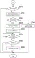
Next, a toilet management method of the toilet system according to the present embodiment will be described. Fig. 11 and 12 are explanatory views of a toilet management method executed by the management server 2 in accordance with the toilet management program.
First, when the user enters the toilet room 14 and the detection unit 46 detects the entry, the control device 44 transmits the identification information of the toilet room 14 to the management server 2 together with the entry time. In addition, when the detection unit 46 detects the exit, the control device 44 transmits the identification information of the toilet room 14 and the exit-related information to the management server 2 in the same manner. In the present embodiment, it is detected that the user enters the toilet compartment 14 when any of the sensors 92, 421, 461, 462, 463 is turned "ON", and it is detected that the user exits the toilet compartment 14 when all the sensors are turned "OFF".
When the identification information and the entry time of the toilet compartment 14 are received from the control device 44, the management server 2 executes the processing shown in fig. 11 and 12 until receiving information that the user exits from the toilet compartment 14.
When the process of fig. 11 is started, the management server 2 requests the control device 44 of the toilet room 14 specified by the received identification information to transmit the detection results of the sensors as the user information, and acquires the detection results, that is, the state of the toilet room 14 from the control device 44 (step S10).
The management server 2 determines whether the user has fallen or not, based on whether or not the detection result satisfies the first condition (step S20).
When it is determined that the fall of the user has occurred (Yes in step S20), the management server 2 transmits a mail notifying the occurrence of the fall to the administrator terminal 3 (step S30). The controller 44 is notified of the occurrence of a fall, and the display on the display part 432 of the controller 43 and the sound output from the speaker 433 output a message such as "a fall has been detected", so that the manager is notified of the fall. Please choose to cancel such a message without help. Accordingly, the user is notified of the fact that the user has fallen, and is notified of the cancellation operation without assistance.
The management server 2 also determines whether or not there is a request for transmitting an image from the administrator terminal 3. When the request for transmitting the image is received from the manager terminal 3 (Yes in step S50), the image of the toilet room 14 captured by the image recording unit 65 is transmitted to the manager terminal 3 (step S60). On the other hand, when the transmission request of the image is not received from the administrator terminal 3 (No in step S50), the image is not transmitted and the process proceeds to step S70.
In step S70, the management server 2 determines whether or not a predetermined time has elapsed after the user entered the toilet compartment 14 and determined that a fall has first occurred in step S20. Here, if it is determined that the predetermined time has not elapsed (No in step S70), the process proceeds to step S210 in fig. 12, and if it is determined that the predetermined time has elapsed (Yes in step S70), the management server 2 determines whether or not a cancel request has been received from the control device 44 or the administrator terminal 3 (step S80). For example, when the user operates the controller 43 and selects cancellation without the degree of rescue, the control device 44 transmits a detection result of the cancellation of the detected fall to the management server 2. When the administrator determines that the image is not necessary to be rescued as a result of the confirmation of the image, the cancellation is input to the administrator terminal 3, and the administrator terminal 3 notifies the management server 2 of the cancellation.
When the management server 2 receives the cancel request from the administrator terminal 3 or the control device 44 (step S80, "Yes"), the process proceeds to step S210 in fig. 12, and when the cancel request is not received (step S80, "No"), the control server performs control so that the door 9 is opened by transmitting a control signal for opening the door 9 to the control device 44. The control of opening the door 9 may be control of opening the doorway 4 by moving the door 9 by the door driving unit 63, or control of unlocking the lock 91 without moving the door 9. For example, if the door 9 can be manually opened by unlocking the lock 91, only the lock 91 is unlocked in step S90, and the door is manually opened after the manager arrives at the toilet compartment 14. Accordingly, the doorway 4 is closed until the manager arrives after the door is controlled to be opened in step S90, and unnecessary opening can be prevented.
Further, even if the lock 91 is unlocked, the door cannot be opened, and the following operation may be performed in step S90: the door 9 is moved by a predetermined amount in the opening direction to maintain a state in which a predetermined gap is opened, and the manager reaches the toilet compartment 14 and then inserts his hand from the gap to operate the operation panel 61, thereby opening the door.
On the other hand, if it is determined in step S20 that the vehicle is not a fall (No in step S20), the management server 2 determines whether the vehicle is an unauthorized intruder based on whether the detection result satisfies the second condition (step S110). If it is determined that the intruder is illegal (Yes in step S110), the management server 2 transmits a mail notifying the presence of the intruder to the manager terminal 3 (step S120).
The management server 2 transmits a control signal for maintaining the closed state of the door 9 to the control device 44, and the door driving unit 63 controls the door 9 and the lock 91 (step S130). In the control for maintaining the closed state of the door 9, the door 9 is closed and locked if the door 9 is in the opened state, and in this locked state, even if the operation panel 61 performs the opening operation, the door 9 is maintained in the closed state without receiving the opening operation.
Next, the management server 2 determines whether or not there is a request for transmitting an image from the administrator terminal 3 (step S140). When receiving the image transmission request from the manager terminal 3 (Yes in step S140), the image in the toilet compartment 14 captured by the image recording unit 65 is transmitted to the manager terminal 3 (step S150). On the other hand, if the request for transmitting the image is not received from the administrator terminal 3 (No in step S140), the process proceeds to step S160 without transmitting the image.
In step S160, the management server 2 determines whether or not a predetermined time has elapsed after the user has entered the toilet room 14 and determined that the unauthorized intruder has first occurred in step S110. Here, when it is determined that the predetermined time has not elapsed (No in step S160), the management server 2 proceeds to step S210 in fig. 12, and when it is determined that the predetermined time has elapsed (Yes in step S160), it is determined whether or not a cancel request has been received from the administrator terminal 3 (step S170). For example, when the manager confirms the result of the image and determines that it is not necessary to control the intruder, or when the manager arrives at the toilet room and then opens the door 9, the manager terminal 3 inputs the cancellation, and the manager terminal 3 notifies the management server 2 of the cancellation.
When the request for cancellation is not received from the administrator terminal 3 (No in step S170), the management server 2 proceeds to step S210 in fig. 12, and when cancellation is received (Yes in step S170), transmits a control signal to the control device 44 to stop the control of maintaining the state of the closed door 9 in step S130 (step S180). Accordingly, when the operation panel 61 is used to open the door, the controller 44 controls the door 9 to open as usual. When the opened door 9 is closed at the time of execution of step S130, control may be performed to move the door 9 in the opening direction and return to the state before execution of step S130.
In step S210, the management server 2 determines whether or not the user has exited from the toilet compartment 14, and if not (step S210, "No"), the process of fig. 12 is terminated. When the user has exited from the toilet compartment 14 (Yes in step S210), the management server 2 acquires and compares the image in the toilet compartment 14 after the user has exited with the image in the toilet compartment 14 before the user entered (step S220).
The management server 2 determines whether or not there is a carry-over according to whether or not the comparison result satisfies the third condition (step S230). Here, when it is determined that there is No carry-over (No in step S230), the management server 2 stores the image obtained in step S220 after the user exits in the memory (step S240), and ends the processing of fig. 12. When the next user enters the toilet room and the comparison in step S220 is performed, the image stored in the memory is used as the image before the user enters.
When it is determined that there is a carry-over (Yes in step S230), the management server 2 transmits information notifying the presence of the carry-over and an image captured by the image recording unit 65 in the toilet compartment 14 to the manager terminal 3 as an email (step S250). Further, the management server 2 notifies the control device 44 of the presence of the left behind object, and outputs the sound output from the speaker 433 as if "there is a left behind object" by displaying the sound on the display part 432 of the controller 43. The word that has retrieved the amnesia asks to choose cancellation. "such information. Accordingly, when the user is notified that the forgotten object has occurred and that the forgotten object has been retrieved, the user is notified to cancel the operation.
The management server 2 determines whether or not a predetermined time has elapsed after the detection of the carry-over in step S230 (step S270), and waits until the predetermined time has elapsed, if the predetermined time has not elapsed (step S270, "No (No)"). The predetermined time may be set arbitrarily, and is, for example, 30 to 120 seconds, preferably 60 to 90 seconds.
When it is determined that the predetermined time has elapsed (Yes at step S270), the management server 2 determines whether or not a cancel request has been received from the control device 44 or the manager terminal 3 (step S280). For example, when the user collects a left behind object and operates the operation unit 431 to input a cancel, the control device 44 transmits a detection result of the detected cancel of the left behind object detected by the management server 2 to the management server 2. When the manager determines that the lock of the door is not necessary as a result of the confirmation of the image, the manager terminal 3 inputs cancellation, and the manager terminal 3 notifies the management server 2 of the cancellation.
When receiving the cancel request from the administrator terminal 3 or the control device 44 (Yes in step S280), the management server 2 ends the process of fig. 12 without controlling the door 9. When the management server 2 does not receive the cancel request (No in step S280), it controls to transmit a control signal for closing the door 9 to the control device 44, and closes the door 9. The control device that has received the control signal for closing the door 9 moves the door 9 by the door driving unit 63 to close and lock the doorway 4. Accordingly, when a user's forgetting object or suspicious object is present in the toilet compartment 14, the door 9 is controlled to be closed.
< effects of the embodiment >
As described above, according to the present embodiment, the type of abnormality can be determined based on which of the first to third conditions is satisfied by the detection result of the detection unit 46, and the door of the toilet compartment can be controlled based on the type of abnormality, that is, the state in the toilet compartment.
In addition, when it is determined that a fall has occurred as a result of the detection result satisfying the first condition, the toilet system of the present embodiment controls the opening door 9 to promptly rescue the user in the toilet.
In addition, when it is determined that the detection result satisfies the second condition and that the candid photograph or the breakdown of the toilet facility 1 has occurred, the toilet system of the present embodiment performs control to maintain the door in the closed state so that the user can stay in the toilet.
Further, the toilet system of the present embodiment can control the closing of the door when the detection result satisfies the third condition and the remaining object exists in the toilet compartment. Therefore, when the user forgets the article in the toilet compartment, the third person can be prevented from taking the forgotten article away by closing the door 9. In addition, when the suspicious object is abandoned in the toilet compartment, the next user can be prevented from inadvertently touching the suspicious object by closing the door 9.
< Others >
The present invention is not limited to the above-described examples of the drawings, and various modifications may be made without departing from the scope of the present invention.
(description of reference numerals)
1: a toilet facility; 2: a management server; 3: a manager terminal; 5: a network; 8: a guide rail; 9: a door;
10: a toilet facility; 14: a toilet compartment; 22: a main storage device; 23: a secondary storage device;
26: a communication bus; 41: a toilet bowl; 42: a seat ring device; 43: a controller; 44: a control device;
46: a detection unit; 61: an operation panel; 63: a door driving unit; 65: an image recording unit;
69: router unit
Claims (8)
1. A toilet system is characterized by comprising:
a detection unit for detecting a state in the toilet compartment;
an abnormality determination unit configured to determine occurrence and type of an abnormality based on a detection result of the detection unit, and notify an administrator terminal of the occurrence of the abnormality when the abnormality is determined to have occurred;
and a door control unit configured to control opening and closing of the door according to a type of the abnormality when it is determined that the request for cancellation is not received from the manager terminal within a predetermined time after the abnormality occurs, and not to control opening and closing of the door when it is determined that the request for cancellation is received from the manager terminal within the predetermined time after the abnormality occurs.
2. Toilet system according to claim 1,
the detection unit detects a state of a user in the toilet compartment based on at least one of a position, a movement, or a shape of an object in the toilet compartment,
when the state of the user satisfies a predetermined first condition, the abnormality determination unit determines that an abnormality has occurred, and the door control unit performs control to open the door.
3. Toilet system according to claim 2,
the first condition is a case where a maximum value of the height of the user detected by the detection unit is equal to or less than a predetermined lower limit value, or a case where the user is stationary for a predetermined time or longer.
4. Toilet system according to claim 1,
the detection unit detects a state of a user in the toilet compartment based on at least one of a position, a movement, or a shape of an object in the toilet compartment,
when the state of the user satisfies a predetermined second condition, the abnormality determination unit determines that an abnormality has occurred, and the door control unit maintains the state in which the door is closed.
5. Toilet system according to claim 4,
the second condition is a case where the user is present beyond a predetermined upper limit value, a case where the user changes a shape of the toilet equipment provided in the toilet compartment, or a case where the user performs a specific operation on the toilet equipment.
6. Toilet system according to claim 1,
the detection unit detects entry/exit of a user into/from the toilet compartment, compares the user's entry into the toilet compartment before the entry with the user's exit, and determines that an abnormality has occurred when an object that is not present in the toilet compartment before the entry is present in the toilet compartment after the exit, and the door control unit controls the door to close the door.
7. A toilet management method, characterized in that a computer performs the steps of:
a detection step of detecting a state in the toilet compartment;
an abnormality determination step of determining the occurrence and type of an abnormality based on a detection result of the detection step;
notifying the occurrence of the abnormality to a manager terminal when it is determined that the abnormality has occurred;
and a door control step of controlling opening and closing of the door in accordance with a type of the abnormality when it is determined that the request for cancellation is not received from the manager terminal within a predetermined time after the abnormality has occurred, and not controlling opening and closing of the door when it is determined that the request for cancellation is received from the manager terminal within the predetermined time after the abnormality has occurred.
8. A storage medium for storing a toilet management program that causes a computer to execute the steps of:
a detection step of detecting a state in the toilet compartment;
an abnormality determination step of determining the occurrence and type of an abnormality based on a detection result of the detection step;
notifying the occurrence of the abnormality to a manager terminal when it is determined that the abnormality has occurred;
and a door control step of controlling opening and closing of the door in accordance with a type of the abnormality when it is determined that the request for cancellation is not received from the manager terminal within a predetermined time after the abnormality has occurred, and not controlling opening and closing of the door when it is determined that the request for cancellation is received from the manager terminal within the predetermined time after the abnormality has occurred.
Applications Claiming Priority (3)
| Application Number | Priority Date | Filing Date | Title |
|---|---|---|---|
| JP2016-199451 | 2016-10-07 | ||
| JP2016199451A JP6636892B2 (en) | 2016-10-07 | 2016-10-07 | Toilet system, toilet management method, and toilet management program |
| PCT/JP2017/036481 WO2018066694A1 (en) | 2016-10-07 | 2017-10-06 | Toilet system, toilet management method, and toilet management program |
Publications (2)
| Publication Number | Publication Date |
|---|---|
| CN109791724A CN109791724A (en) | 2019-05-21 |
| CN109791724B true CN109791724B (en) | 2021-01-29 |
Family
ID=61831900
Family Applications (1)
| Application Number | Title | Priority Date | Filing Date |
|---|---|---|---|
| CN201780061515.4A Active CN109791724B (en) | 2016-10-07 | 2017-10-06 | Toilet system, toilet management method, and storage medium |
Country Status (6)
| Country | Link |
|---|---|
| US (1) | US10955822B2 (en) |
| EP (1) | EP3525188A4 (en) |
| JP (1) | JP6636892B2 (en) |
| CN (1) | CN109791724B (en) |
| SG (1) | SG11201903078UA (en) |
| WO (1) | WO2018066694A1 (en) |
Families Citing this family (7)
| Publication number | Priority date | Publication date | Assignee | Title |
|---|---|---|---|---|
| JP6829447B2 (en) * | 2019-02-22 | 2021-02-10 | 株式会社 千葉通信システム | Toilet management system |
| CN110443978B (en) * | 2019-08-08 | 2021-06-18 | 南京联舜科技有限公司 | Tumble alarm device and method |
| CN110738819A (en) * | 2019-10-23 | 2020-01-31 | 合肥盛东信息科技有限公司 | non-wearable toilet tumble monitoring and alarming system |
| CN110989424B (en) * | 2019-11-15 | 2023-08-11 | 得力集团有限公司 | Wireless low-power-consumption human body induction device and application method thereof |
| CN111012359A (en) * | 2019-12-26 | 2020-04-17 | 湖南大学 | Tumble detection method, tumble detection device and storage medium |
| CN113790764A (en) * | 2021-09-28 | 2021-12-14 | 安徽省产品质量监督检验研究院(国家排灌及节水设备产品质量监督检验中心) | Comprehensive detection method for intelligent closestool |
| CN114753757A (en) * | 2022-03-14 | 2022-07-15 | 青岛海尔空调器有限总公司 | Method and device for toilet control and terminal equipment |
Citations (3)
| Publication number | Priority date | Publication date | Assignee | Title |
|---|---|---|---|---|
| JP2002188204A (en) * | 2000-12-22 | 2002-07-05 | Toto Ltd | Toilet booth system |
| JP2007241446A (en) * | 2006-03-06 | 2007-09-20 | Toto Ltd | Security system |
| CN105189879A (en) * | 2013-04-30 | 2015-12-23 | 株式会社Ntt设施 | Toilet system |
Family Cites Families (7)
| Publication number | Priority date | Publication date | Assignee | Title |
|---|---|---|---|---|
| AU1966099A (en) | 1997-12-03 | 1999-06-16 | Walter Di Fulvio | Control device for a toilet |
| AUPQ303799A0 (en) * | 1999-09-24 | 1999-10-21 | Right Hemisphere Pty Limited | Safety cubicle |
| JP2007058406A (en) | 2005-08-23 | 2007-03-08 | Toto Ltd | Security system |
| JP4991771B2 (en) | 2009-02-06 | 2012-08-01 | 有限会社メディカルソフト | Alarm device |
| US20110316703A1 (en) * | 2010-04-29 | 2011-12-29 | Andy Butler | System and Method for Ensuring Sanitation Procedures in Restrooms |
| JP6261946B2 (en) * | 2013-10-29 | 2018-01-17 | 株式会社木村技研 | Toilet system |
| DE102017010521A1 (en) * | 2017-11-14 | 2019-05-16 | Drägerwerk AG & Co. KGaA | Device, method and computer program for a medical device |
-
2016
- 2016-10-07 JP JP2016199451A patent/JP6636892B2/en active Active
-
2017
- 2017-10-06 CN CN201780061515.4A patent/CN109791724B/en active Active
- 2017-10-06 US US16/339,870 patent/US10955822B2/en active Active
- 2017-10-06 SG SG11201903078UA patent/SG11201903078UA/en unknown
- 2017-10-06 WO PCT/JP2017/036481 patent/WO2018066694A1/en unknown
- 2017-10-06 EP EP17858530.3A patent/EP3525188A4/en active Pending
Patent Citations (3)
| Publication number | Priority date | Publication date | Assignee | Title |
|---|---|---|---|---|
| JP2002188204A (en) * | 2000-12-22 | 2002-07-05 | Toto Ltd | Toilet booth system |
| JP2007241446A (en) * | 2006-03-06 | 2007-09-20 | Toto Ltd | Security system |
| CN105189879A (en) * | 2013-04-30 | 2015-12-23 | 株式会社Ntt设施 | Toilet system |
Also Published As
| Publication number | Publication date |
|---|---|
| SG11201903078UA (en) | 2019-05-30 |
| JP2018060475A (en) | 2018-04-12 |
| JP6636892B2 (en) | 2020-01-29 |
| CN109791724A (en) | 2019-05-21 |
| EP3525188A1 (en) | 2019-08-14 |
| US20190243342A1 (en) | 2019-08-08 |
| WO2018066694A1 (en) | 2018-04-12 |
| EP3525188A4 (en) | 2020-06-24 |
| US10955822B2 (en) | 2021-03-23 |
Similar Documents
| Publication | Publication Date | Title |
|---|---|---|
| CN109791724B (en) | Toilet system, toilet management method, and storage medium | |
| JP6261946B2 (en) | Toilet system | |
| CN111542866B (en) | Toilet management system and toilet management method | |
| CN109565576B (en) | Safety management system and method | |
| JP6659033B2 (en) | Toilet system | |
| JP2017163289A (en) | Security management system | |
| JP2017159033A (en) | Ceiling concealed type toilet booth overstaying suppression device | |
| JP6258910B2 (en) | Private room management system | |
| WO2001024133A1 (en) | Safety cubicle with alarm | |
| JP4933943B2 (en) | Kitchen equipment control system | |
| JP2002266410A (en) | Toilet system detecting service condition, and closet seat unit | |
| WO2017150635A1 (en) | Roof-space-hidden device for preventing long occupation of toilet booth | |
| CN110945571A (en) | Security management system | |
| JP7326751B2 (en) | toilet system | |
| JP7467983B2 (en) | Toilet System | |
| JP2005301778A (en) | Indoor accident detecting apparatus and program therefor | |
| JP2004199122A (en) | Anomaly detector | |
| JP7250188B2 (en) | toilet system | |
| JP7489633B2 (en) | Security Management Systems | |
| WO2022004241A1 (en) | Receiver, signal processing system, and human analysis system | |
| JP2022027121A (en) | Toilet system and toilet management method | |
| JP2022126596A (en) | Automatic door device, control method of automatic door device, and control program of automatic door device | |
| CN117593850A (en) | Video camera system | |
| JP2022065936A (en) | Toilet guide apparatus | |
| JP2023045903A (en) | Automatic door device, control method of automatic door device, and control program of automatic door device |
Legal Events
| Date | Code | Title | Description |
|---|---|---|---|
| PB01 | Publication | ||
| PB01 | Publication | ||
| SE01 | Entry into force of request for substantive examination | ||
| SE01 | Entry into force of request for substantive examination | ||
| GR01 | Patent grant | ||
| GR01 | Patent grant |