CN109790789B - Method for detecting a phase difference between an inlet valve stroke and an outlet valve stroke of an internal combustion engine - Google Patents
Method for detecting a phase difference between an inlet valve stroke and an outlet valve stroke of an internal combustion engine Download PDFInfo
- Publication number
- CN109790789B CN109790789B CN201780062806.5A CN201780062806A CN109790789B CN 109790789 B CN109790789 B CN 109790789B CN 201780062806 A CN201780062806 A CN 201780062806A CN 109790789 B CN109790789 B CN 109790789B
- Authority
- CN
- China
- Prior art keywords
- phase difference
- equal
- valve stroke
- lines
- internal combustion
- Prior art date
- Legal status (The legal status is an assumption and is not a legal conclusion. Google has not performed a legal analysis and makes no representation as to the accuracy of the status listed.)
- Active
Links
Images


Classifications
-
- F—MECHANICAL ENGINEERING; LIGHTING; HEATING; WEAPONS; BLASTING
- F02—COMBUSTION ENGINES; HOT-GAS OR COMBUSTION-PRODUCT ENGINE PLANTS
- F02D—CONTROLLING COMBUSTION ENGINES
- F02D41/00—Electrical control of supply of combustible mixture or its constituents
- F02D41/0002—Controlling intake air
-
- F—MECHANICAL ENGINEERING; LIGHTING; HEATING; WEAPONS; BLASTING
- F01—MACHINES OR ENGINES IN GENERAL; ENGINE PLANTS IN GENERAL; STEAM ENGINES
- F01L—CYCLICALLY OPERATING VALVES FOR MACHINES OR ENGINES
- F01L1/00—Valve-gear or valve arrangements, e.g. lift-valve gear
- F01L1/34—Valve-gear or valve arrangements, e.g. lift-valve gear characterised by the provision of means for changing the timing of the valves without changing the duration of opening and without affecting the magnitude of the valve lift
- F01L1/344—Valve-gear or valve arrangements, e.g. lift-valve gear characterised by the provision of means for changing the timing of the valves without changing the duration of opening and without affecting the magnitude of the valve lift changing the angular relationship between crankshaft and camshaft, e.g. using helicoidal gear
-
- F—MECHANICAL ENGINEERING; LIGHTING; HEATING; WEAPONS; BLASTING
- F01—MACHINES OR ENGINES IN GENERAL; ENGINE PLANTS IN GENERAL; STEAM ENGINES
- F01L—CYCLICALLY OPERATING VALVES FOR MACHINES OR ENGINES
- F01L13/00—Modifications of valve-gear to facilitate reversing, braking, starting, changing compression ratio, or other specific operations
- F01L13/0015—Modifications of valve-gear to facilitate reversing, braking, starting, changing compression ratio, or other specific operations for optimising engine performances by modifying valve lift according to various working parameters, e.g. rotational speed, load, torque
-
- F—MECHANICAL ENGINEERING; LIGHTING; HEATING; WEAPONS; BLASTING
- F02—COMBUSTION ENGINES; HOT-GAS OR COMBUSTION-PRODUCT ENGINE PLANTS
- F02D—CONTROLLING COMBUSTION ENGINES
- F02D13/00—Controlling the engine output power by varying inlet or exhaust valve operating characteristics, e.g. timing
- F02D13/02—Controlling the engine output power by varying inlet or exhaust valve operating characteristics, e.g. timing during engine operation
- F02D13/0203—Variable control of intake and exhaust valves
- F02D13/0215—Variable control of intake and exhaust valves changing the valve timing only
- F02D13/0219—Variable control of intake and exhaust valves changing the valve timing only by shifting the phase, i.e. the opening periods of the valves are constant
-
- F—MECHANICAL ENGINEERING; LIGHTING; HEATING; WEAPONS; BLASTING
- F02—COMBUSTION ENGINES; HOT-GAS OR COMBUSTION-PRODUCT ENGINE PLANTS
- F02D—CONTROLLING COMBUSTION ENGINES
- F02D41/00—Electrical control of supply of combustible mixture or its constituents
- F02D41/009—Electrical control of supply of combustible mixture or its constituents using means for generating position or synchronisation signals
-
- F—MECHANICAL ENGINEERING; LIGHTING; HEATING; WEAPONS; BLASTING
- F02—COMBUSTION ENGINES; HOT-GAS OR COMBUSTION-PRODUCT ENGINE PLANTS
- F02D—CONTROLLING COMBUSTION ENGINES
- F02D41/00—Electrical control of supply of combustible mixture or its constituents
- F02D41/02—Circuit arrangements for generating control signals
- F02D41/14—Introducing closed-loop corrections
- F02D41/1401—Introducing closed-loop corrections characterised by the control or regulation method
-
- F—MECHANICAL ENGINEERING; LIGHTING; HEATING; WEAPONS; BLASTING
- F02—COMBUSTION ENGINES; HOT-GAS OR COMBUSTION-PRODUCT ENGINE PLANTS
- F02D—CONTROLLING COMBUSTION ENGINES
- F02D41/00—Electrical control of supply of combustible mixture or its constituents
- F02D41/24—Electrical control of supply of combustible mixture or its constituents characterised by the use of digital means
- F02D41/2406—Electrical control of supply of combustible mixture or its constituents characterised by the use of digital means using essentially read only memories
- F02D41/2425—Particular ways of programming the data
- F02D41/2429—Methods of calibrating or learning
- F02D41/2432—Methods of calibration
-
- F—MECHANICAL ENGINEERING; LIGHTING; HEATING; WEAPONS; BLASTING
- F02—COMBUSTION ENGINES; HOT-GAS OR COMBUSTION-PRODUCT ENGINE PLANTS
- F02D—CONTROLLING COMBUSTION ENGINES
- F02D41/00—Electrical control of supply of combustible mixture or its constituents
- F02D41/24—Electrical control of supply of combustible mixture or its constituents characterised by the use of digital means
- F02D41/2406—Electrical control of supply of combustible mixture or its constituents characterised by the use of digital means using essentially read only memories
- F02D41/2425—Particular ways of programming the data
- F02D41/2429—Methods of calibrating or learning
- F02D41/2451—Methods of calibrating or learning characterised by what is learned or calibrated
- F02D41/2464—Characteristics of actuators
-
- F—MECHANICAL ENGINEERING; LIGHTING; HEATING; WEAPONS; BLASTING
- F02—COMBUSTION ENGINES; HOT-GAS OR COMBUSTION-PRODUCT ENGINE PLANTS
- F02D—CONTROLLING COMBUSTION ENGINES
- F02D41/00—Electrical control of supply of combustible mixture or its constituents
- F02D41/24—Electrical control of supply of combustible mixture or its constituents characterised by the use of digital means
- F02D41/26—Electrical control of supply of combustible mixture or its constituents characterised by the use of digital means using computer, e.g. microprocessor
- F02D41/28—Interface circuits
-
- F—MECHANICAL ENGINEERING; LIGHTING; HEATING; WEAPONS; BLASTING
- F01—MACHINES OR ENGINES IN GENERAL; ENGINE PLANTS IN GENERAL; STEAM ENGINES
- F01L—CYCLICALLY OPERATING VALVES FOR MACHINES OR ENGINES
- F01L1/00—Valve-gear or valve arrangements, e.g. lift-valve gear
- F01L1/34—Valve-gear or valve arrangements, e.g. lift-valve gear characterised by the provision of means for changing the timing of the valves without changing the duration of opening and without affecting the magnitude of the valve lift
- F01L1/344—Valve-gear or valve arrangements, e.g. lift-valve gear characterised by the provision of means for changing the timing of the valves without changing the duration of opening and without affecting the magnitude of the valve lift changing the angular relationship between crankshaft and camshaft, e.g. using helicoidal gear
- F01L2001/34486—Location and number of the means for changing the angular relationship
- F01L2001/34496—Two phasers on different camshafts
-
- F—MECHANICAL ENGINEERING; LIGHTING; HEATING; WEAPONS; BLASTING
- F01—MACHINES OR ENGINES IN GENERAL; ENGINE PLANTS IN GENERAL; STEAM ENGINES
- F01L—CYCLICALLY OPERATING VALVES FOR MACHINES OR ENGINES
- F01L2800/00—Methods of operation using a variable valve timing mechanism
- F01L2800/11—Fault detection, diagnosis
-
- F—MECHANICAL ENGINEERING; LIGHTING; HEATING; WEAPONS; BLASTING
- F01—MACHINES OR ENGINES IN GENERAL; ENGINE PLANTS IN GENERAL; STEAM ENGINES
- F01L—CYCLICALLY OPERATING VALVES FOR MACHINES OR ENGINES
- F01L2800/00—Methods of operation using a variable valve timing mechanism
- F01L2800/14—Determining a position, e.g. phase or lift
-
- F—MECHANICAL ENGINEERING; LIGHTING; HEATING; WEAPONS; BLASTING
- F01—MACHINES OR ENGINES IN GENERAL; ENGINE PLANTS IN GENERAL; STEAM ENGINES
- F01L—CYCLICALLY OPERATING VALVES FOR MACHINES OR ENGINES
- F01L2820/00—Details on specific features characterising valve gear arrangements
- F01L2820/04—Sensors
- F01L2820/041—Camshafts position or phase sensors
-
- F—MECHANICAL ENGINEERING; LIGHTING; HEATING; WEAPONS; BLASTING
- F01—MACHINES OR ENGINES IN GENERAL; ENGINE PLANTS IN GENERAL; STEAM ENGINES
- F01L—CYCLICALLY OPERATING VALVES FOR MACHINES OR ENGINES
- F01L2820/00—Details on specific features characterising valve gear arrangements
- F01L2820/04—Sensors
- F01L2820/042—Crankshafts position
-
- F—MECHANICAL ENGINEERING; LIGHTING; HEATING; WEAPONS; BLASTING
- F01—MACHINES OR ENGINES IN GENERAL; ENGINE PLANTS IN GENERAL; STEAM ENGINES
- F01L—CYCLICALLY OPERATING VALVES FOR MACHINES OR ENGINES
- F01L2820/00—Details on specific features characterising valve gear arrangements
- F01L2820/04—Sensors
- F01L2820/043—Pressure
-
- F—MECHANICAL ENGINEERING; LIGHTING; HEATING; WEAPONS; BLASTING
- F02—COMBUSTION ENGINES; HOT-GAS OR COMBUSTION-PRODUCT ENGINE PLANTS
- F02D—CONTROLLING COMBUSTION ENGINES
- F02D41/00—Electrical control of supply of combustible mixture or its constituents
- F02D41/0002—Controlling intake air
- F02D2041/001—Controlling intake air for engines with variable valve actuation
-
- F—MECHANICAL ENGINEERING; LIGHTING; HEATING; WEAPONS; BLASTING
- F02—COMBUSTION ENGINES; HOT-GAS OR COMBUSTION-PRODUCT ENGINE PLANTS
- F02D—CONTROLLING COMBUSTION ENGINES
- F02D41/00—Electrical control of supply of combustible mixture or its constituents
- F02D41/02—Circuit arrangements for generating control signals
- F02D41/14—Introducing closed-loop corrections
- F02D41/1401—Introducing closed-loop corrections characterised by the control or regulation method
- F02D2041/1433—Introducing closed-loop corrections characterised by the control or regulation method using a model or simulation of the system
-
- F—MECHANICAL ENGINEERING; LIGHTING; HEATING; WEAPONS; BLASTING
- F02—COMBUSTION ENGINES; HOT-GAS OR COMBUSTION-PRODUCT ENGINE PLANTS
- F02D—CONTROLLING COMBUSTION ENGINES
- F02D41/00—Electrical control of supply of combustible mixture or its constituents
- F02D41/24—Electrical control of supply of combustible mixture or its constituents characterised by the use of digital means
- F02D41/26—Electrical control of supply of combustible mixture or its constituents characterised by the use of digital means using computer, e.g. microprocessor
- F02D41/28—Interface circuits
- F02D2041/286—Interface circuits comprising means for signal processing
- F02D2041/288—Interface circuits comprising means for signal processing for performing a transformation into the frequency domain, e.g. Fourier transformation
-
- F—MECHANICAL ENGINEERING; LIGHTING; HEATING; WEAPONS; BLASTING
- F02—COMBUSTION ENGINES; HOT-GAS OR COMBUSTION-PRODUCT ENGINE PLANTS
- F02D—CONTROLLING COMBUSTION ENGINES
- F02D2200/00—Input parameters for engine control
- F02D2200/02—Input parameters for engine control the parameters being related to the engine
- F02D2200/024—Fluid pressure of lubricating oil or working fluid
-
- F—MECHANICAL ENGINEERING; LIGHTING; HEATING; WEAPONS; BLASTING
- F02—COMBUSTION ENGINES; HOT-GAS OR COMBUSTION-PRODUCT ENGINE PLANTS
- F02D—CONTROLLING COMBUSTION ENGINES
- F02D2200/00—Input parameters for engine control
- F02D2200/02—Input parameters for engine control the parameters being related to the engine
- F02D2200/04—Engine intake system parameters
- F02D2200/0406—Intake manifold pressure
-
- Y—GENERAL TAGGING OF NEW TECHNOLOGICAL DEVELOPMENTS; GENERAL TAGGING OF CROSS-SECTIONAL TECHNOLOGIES SPANNING OVER SEVERAL SECTIONS OF THE IPC; TECHNICAL SUBJECTS COVERED BY FORMER USPC CROSS-REFERENCE ART COLLECTIONS [XRACs] AND DIGESTS
- Y02—TECHNOLOGIES OR APPLICATIONS FOR MITIGATION OR ADAPTATION AGAINST CLIMATE CHANGE
- Y02T—CLIMATE CHANGE MITIGATION TECHNOLOGIES RELATED TO TRANSPORTATION
- Y02T10/00—Road transport of goods or passengers
- Y02T10/10—Internal combustion engine [ICE] based vehicles
- Y02T10/12—Improving ICE efficiencies
-
- Y—GENERAL TAGGING OF NEW TECHNOLOGICAL DEVELOPMENTS; GENERAL TAGGING OF CROSS-SECTIONAL TECHNOLOGIES SPANNING OVER SEVERAL SECTIONS OF THE IPC; TECHNICAL SUBJECTS COVERED BY FORMER USPC CROSS-REFERENCE ART COLLECTIONS [XRACs] AND DIGESTS
- Y02—TECHNOLOGIES OR APPLICATIONS FOR MITIGATION OR ADAPTATION AGAINST CLIMATE CHANGE
- Y02T—CLIMATE CHANGE MITIGATION TECHNOLOGIES RELATED TO TRANSPORTATION
- Y02T10/00—Road transport of goods or passengers
- Y02T10/10—Internal combustion engine [ICE] based vehicles
- Y02T10/40—Engine management systems
Abstract
The invention relates to a method for combined identification of an inlet valve stroke phase difference and an outlet valve stroke phase difference of a cylinder of an internal combustion engine, and is based on the fact that: the phase position and the amplitude of the selected signal frequency of the pressure oscillations relative to the crankshaft phase angle signal are obtained from the dynamic pressure oscillations of the intake air in the air intake tract, which can be assigned to the respective cylinder. Based on these phase positions and amplitudes, the inlet valve stroke phase difference and the outlet valve stroke phase difference are then determined by using the equal phase position lines and the equal amplitude lines. Particularly precise recognition of the control timing can thus be carried out in a simple and inexpensive manner, whereby advantages with regard to emissions, consumption, smoothness and power of operation of the engine and improvements in closed-loop and open-loop controllability can be achieved.
Description
Technical Field
The invention relates to a method by means of which a phase difference of valve strokes of inlet and outlet valves of a reciprocating piston internal combustion engine can be identified during operation by evaluating dynamic pressure oscillations of the intake air, which are measured in the air intake duct, in a combined form.
Background
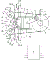
Reciprocating piston internal combustion engines (which will also be referred to simply as internal combustion engines hereinafter) have one or more cylinders in each case one reciprocating piston arranged therein. In order to illustrate the principle of a reciprocating piston internal combustion engine, reference will be made in the following to fig. 1, which shows by way of example the cylinders and most important functional units of an internal combustion engine, which may also be a multi-cylinder internal combustion engine.
A respective reciprocating piston 6 is arranged in a linearly movable manner in the respective cylinder 2 and, together with the cylinder 2, encloses the combustion chamber 3. The respective reciprocating piston 6 is connected to a respective crank pin 8 of a crankshaft 9 by means of a so-called connecting rod 7, wherein the crank pin 8 is eccentrically arranged with respect to a crankshaft axis of rotation 9 a. The reciprocating pistons 6 are driven linearly "downward" due to the combustion of the fuel-air mixture in the combustion chamber 3. The translational stroke movement of the reciprocating piston 6 is transmitted to the crankshaft 9 by means of the connecting rod 7 and the crank pin 8 and converted into a rotational movement of the crankshaft 9, which causes the reciprocating piston 6 (after it has passed the bottom dead center in the cylinder 2) to move "upwards" again in the opposite direction, far away from the top dead center. In order to allow continuous operation of the internal combustion engine 1, during the so-called working cycle of the cylinders 2, it is necessary to first fill the combustion chambers 3 with a fuel-air mixture, to have the fuel-air mixture compressed in the combustion chambers 3 and then ignited and combusted in an expanding manner in order to drive the reciprocating pistons 6, and finally to have the exhaust gases remaining after combustion expelled from the combustion chambers 3. The successive repetition of this sequence results in continuous operation of the internal combustion engine 1, in which work is output in proportion to the combustion energy.
Depending on the engine concept, the working cycle of the cylinder 2 is divided into two strokes distributed over one crankshaft rotation (360 °) (two-stroke engine) or four strokes distributed over two crankshaft rotations (720 °) (four-stroke engine).
Four-stroke engines have been identified heretofore as drivers for motor vehicles. During the intake stroke, due to the downward movement of the reciprocating piston 6, a fuel-air mixture or only fresh air (in the case of direct fuel injection) is introduced from the air intake duct 20 into the combustion chamber 3. During the following compression stroke, due to the upward movement of the reciprocating piston 6, a fuel-air mixture or fresh air is compressed in the combustion chamber 3 and, where appropriate, fuel is injected solely directly into the combustion chamber 3 by means of the injection valve 5 (which belongs to the fuel supply system). During the following work stroke, the fuel-air mixture is ignited by means of the ignition plug 4, burns in an expansion action and expands such that the reciprocating piston 6 moves downward, thereby outputting work. Finally, in the exhaust stroke, the remaining exhaust gas is discharged from the combustion chamber 3 into the exhaust outlet passage 30 by another upward movement of the reciprocating piston 6.
The delimitation of the combustion chamber 3 with respect to the air intake duct 20 or the exhaust gas outlet duct 30 of the internal combustion engine is usually (and in particular in the example on which this is based) effected by means of an inlet valve 22 and an outlet valve 32. In the current state of the art, the valves are actuated by means of at least one camshaft. The example shown has an inlet camshaft 23 for actuating the inlet valve 22 and has an outlet camshaft 33 for actuating the outlet valve 32. There are also usually further mechanical components for force transmission (not shown here) which are arranged between the valve and the respective camshaft, which components may also comprise valve play compensation mechanisms (e.g. barrel tappets, rocker levers, finger rockers, tappets, hydraulic tappets, etc.).
The inlet camshaft 23 and the outlet camshaft 33 are driven by means of the internal combustion engine 1 itself. For this purpose, the inlet camshaft 23 and the outlet camshaft 33 are coupled in each case to the crankshaft 9 by means of a suitable inlet camshaft control adapter 24 and outlet camshaft control adapter 34 at predetermined positions relative to one another and to the crankshaft 9 by means of the corresponding crankshaft control adapter 10, by using a control mechanism 40, such as, for example, a toothed gear, sprocket or pulley, which control mechanism 40 has, for example, a toothed gear mechanism, a control chain or a toothed control belt, the crankshaft control adapter 10 being embodied correspondingly as a toothed gear, sprocket or pulley. By means of this connection, the rotational position of the inlet camshaft 23 and the outlet camshaft 33 relative to the rotational position of the crankshaft 9 is in principle defined. By way of example, fig. 1 shows the coupling between the inlet camshaft 23 and the outlet camshaft 33 and the crankshaft 9 by means of a pulley and a toothed control belt.
The angle of rotation covered by the crankshaft during one working cycle will be referred to hereinafter as the working phase or simply the phase. The angle of rotation covered by the crankshaft in one operating phase is accordingly referred to as the phase angle. The respective current crankshaft phase angle of the crankshaft 9 can be continuously detected by means of a position encoder 43 and an associated crankshaft position sensor 41, said position encoder 43 being connected to the crankshaft 9 or to the crankshaft control adapter 10. Here, the position encoder may, for example, be formed as a toothed gear with a plurality of teeth, which are arranged so as to be equidistantly distributed over the circumference, wherein the number of individual teeth determines the resolution of the crankshaft phase angle signal.
It is also possible, if appropriate, for the current phase angles of the inlet camshaft 23 and the outlet camshaft 33 to be detected continuously by means of a corresponding position encoder 43 and an associated camshaft position sensor 42.
Since, as a result of the predetermined mechanical coupling, the respective crank pin 8 and the reciprocating piston 6 following it, the inlet camshaft 23 and the respective inlet valve 22 following it, and the outlet camshaft 33 and the respective outlet valve 32 following it move in a predetermined relationship with respect to one another and in a manner dependent on the crankshaft rotation, the functional components run synchronously through the respective working phases with respect to the crankshaft. The respective rotational and stroke positions of the reciprocating piston 6, the inlet valve 22 and the outlet valve 32 may thus be set (in view of the respective gear ratios) in relation to the crankshaft phase angle of the crankshaft 9 predetermined by the crankshaft position sensor 41. In an ideal internal combustion engine, each particular crankshaft phase angle may therefore be assigned a particular crankpin angle HZW (fig. 2), a particular piston stroke, a particular inlet camshaft angle (and therefore a particular inlet valve stroke), and also a particular outlet camshaft angle (and therefore a particular outlet valve stroke). That is, all of the components move in phase or in phase with the rotating crankshaft 9.
In modern internal combustion engines 1, however, additional positioning elements may be provided in the mechanical coupling path between the crankshaft 9 and the inlet and outlet camshafts 23, 33, for example in such a way as to be integrated into the inlet and outlet camshaft adapters 24, 34, which achieve the desired controllable phase shift between the crankshaft 9 and the inlet and outlet camshafts 23, 33. These positioning elements are known as so-called phase adjusters in so-called variable valve drives.
Also shown symbolically is an electronic, programmable engine control unit 50 (CPU) equipped with signal inputs for receiving various sensor signals and signal and power outputs for actuating corresponding positioning units and actuators for controlling engine functions.
For optimal operation of the internal combustion engine (with respect to emissions, consumption, power, running smoothness, etc.), further parameters of the fresh charge gas introduced into the combustion chamber during the intake stroke, such as for example the amount of fuel to be supplied, should be known as much as possible in order to enable combustion, and this amount of fuel may be directly injected in coordination with the fresh charge gas. The so-called charge exchange (i.e. the intake of fresh gas and the discharge of exhaust gas) is in this case highly dependent on the control timing of the inlet valve 22 and the outlet valve 32, i.e. on the profile of the respective valve stroke relative to time in relation to the profile of the piston stroke relative to time. In other words, during operation, charge exchange is dependent on the phase position of the inlet and outlet valves relative to the crankshaft phase angle (and thus relative to the phase position of the reciprocating pistons).
The prior art for obtaining fresh charge gas and for coordinating the control parameters of the internal combustion engine associated therewith comprises measuring the operating parameters of a so-called reference internal combustion engine in all occurring operating states, for example in dependence on the rotational speed, the load, valve control timings which may be predetermined, where appropriate, by means of a phase regulator, an exhaust turbocharger or a super-supercharger or the like, and storing these measurements representing the behavior, or derivatives or model methods thereof, on the engine control unit of the corresponding mass-produced internal combustion engine. All structurally identical, mass-produced internal combustion engines of the same type series are then operated with the reference data set generated.
Deviations of the actual relative position between the inlet and outlet valves and the crankshaft phase angle or the reciprocating piston position of a mass-produced internal combustion engine, for example due to manufacturing tolerances, from the ideal reference position of the reference internal combustion engine (that is to say the phase difference of the inlet valve stroke, the phase difference of the outlet valve stroke and, where appropriate, the piston stroke phase difference in relation to the crankshaft phase angle or the phase position of the crankshaft predetermined by the crankshaft position sensor) have the following effects: the actual inspired fresh charge gas deviates from the fresh charge gas determined as the reference and therefore the control parameters based on the reference data set are not optimal. During operation of the internal combustion engine, these errors may have adverse effects with respect to emissions, consumption, power, operational smoothness, and the like.
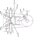
In order to illustrate possible deviations occurring in a mass-produced internal combustion engine, and to define the nomenclature of said deviations, reference will be made hereinafter to fig. 2, which shows the internal combustion engine from fig. 1, but in fig. 2, the reference numerals shown in fig. 1 have been omitted and only the corresponding deviations have been designated for a better overview.
Starting from a reference position of a position encoder 43 arranged on the crankshaft control adapter 10, whose phase angle is detected by the crankshaft position sensor 41, a plurality of tolerance chains result which lead to deviations of the phase positions of the reciprocating piston 6, the inlet valve 22 and the outlet valve 32 in relation to an ideal reference phase position, which are also referred to as phase differences in the following.
Here, the piston stroke phase difference Δ KH is caused by, for example, a deviation of the crank pin angle HZW with respect to a reference position of the crankshaft position sensor 41 (so-called crank pin angle difference HZW) and due to different dimensional tolerances (not shown) of the connecting rod 7 and the reciprocating piston 6.
Further, the inlet valve stroke phase difference Δ EVH is caused by, for example, an offset of the cam position (the so-called inlet camshaft angle difference ENW) and mechanical tolerances (not shown) of the inlet camshaft control adapter 24 and the control mechanism 40. If a phase adjuster for the inlet camshaft is present, the inlet camshaft adjustment angle ENVW or its deviation from the setpoint can also be taken into account.
In the same way, the outlet valve stroke phase difference AVH is caused by, for example, a deviation of the cam position (so-called outlet camshaft angle difference ANW) and mechanical tolerances (not shown) of the outlet camshaft control adapter 24 and the control mechanism 40. If a phase adjuster for the outlet camshaft is present, the outlet camshaft adjustment angle ANVW or its deviation from the setpoint can also be taken into account.
Possible causes of the described deviations may be, for example:
manufacturing and/or assembly tolerances of the mechanical parts involved, and
wear phenomena, such as for example the lengthening of a control chain or toothed belt by means of which the crankshaft and the camshaft are coupled, an
Elastic or plastic deformation phenomena caused by high mechanical load conditions.
The previous solutions to the described problems according to the current state of the art here consist in principle in detecting and quantifying deviations occurring between the reference internal combustion engine and the mass-produced internal combustion engine in order to be able to implement countermeasures for correction or compensation by adjustment of the control parameters.
Furthermore, it has heretofore been sought to counteract this problem by minimizing manufacturing and assembly tolerances. Furthermore, control timings are measured on the respective static mass-produced internal combustion engines, for example, on the basis of valve stroke positions, cam profiles (cam profiles) and the like, and during the assembly process, the internal combustion engines are adjusted accordingly.
Furthermore, the most known systems currently operate with a reference point system (position feedback). Here, in each case one position marker which can be detected by means of a sensor is placed on the crankshaft and on the inlet camshaft and/or on the outlet camshaft, or also on the respective crankshaft control adapter and on the inlet camshaft control adapter and/or on the outlet camshaft control adapter, or also on a phase adjuster which can be provided, etc. In this way, the relative phase position between the crankshaft and the respective inlet camshaft and/or outlet camshaft may be obtained and deviations associated with the desired reference values may be identified. The undesired effects of the deviations can then be counteracted in the control unit by means of an adjustment or correction of the corresponding control parameters in a manner dependent on the deviations obtained.
In principle, however, only some of the occurring tolerances can be identified by means of the method. For example, it is therefore not possible to detect an angular deviation due to the position deviation of the respective position mark itself relative to the camshaft, or the inlet camshaft angle difference Δ ENW or the outlet camshaft angle difference Δ ANW relative to the respective reference position.
Other methods such as evaluating knock sensor signals, evaluating cylinder pressure signals are also known.
Furthermore, US 6,804,997B 1 has disclosed an engine control device for determining the phase position of the crankshaft by monitoring and evaluating pressure fluctuations of the intake air in the air intake. The control device is designed to determine intake air pressure fluctuations indicative of intake air events, and therefore, the crankshaft phase position associated therewith and the corresponding period of the engine cycle. The control device uses these information items to obtain the crankshaft rotational speed and the phase position of the crankshaft in order to control the fuel injection and ignition characteristics of the engine. The control timing of the inlet and outlet valves (that is to say the inlet and outlet valve stroke phase differences, where appropriate) is not taken into account in this case and may in some cases significantly affect the result.
Document DE 102005007057 discloses a closed-loop control method for the throttle flap (throttle flap) air flow in the intake tract of an internal combustion engine, which throttle flap air flow is controlled in a closed-loop manner, wherein pressure pulsations of the intake air in the air intake tract are taken into account in the closed-loop control of the fluid flow, which are also influenced in particular by the valve control timing of the internal combustion engine. For this purpose, the pressure pulsations are analyzed by means of a fast fourier transformation and the amplitude information is summarized as a distortion factor which is taken into account as an additional input variable of a multidimensional mathematical closed-loop control model, for example for the throttle flap air flow. Specific conclusions with regard to the valve control timing of the internal combustion engine (that is to say the inlet valve stroke phase difference and the outlet valve stroke phase difference which may also be present) cannot be drawn with the aid of this method.
Document DE 3506114 a1 discloses a method for open-loop or closed-loop control of an internal combustion engine, in which at least one manipulated variable of the internal combustion engine is controlled in a manner dependent on an operating variable, which comprises at least a part of an oscillation spectrum of the internal combustion engine as information such as, for example, a gas pressure signal. For this purpose, a value spectrum (as part of the oscillation spectrum) contained in the detected manipulated variable is determined from the manipulated variable by means of a discrete fourier transformation and is used as a measurement spectrum and compared with a reference spectrum. The manipulated variable of the internal combustion engine to be controlled is then controlled as a function of the deviation between the measured spectrum and the reference spectrum. Specific conclusions regarding valve control timing and piston stroke position of an internal combustion engine cannot be easily drawn with the aid of this method.
Document US 20090312932 a1 discloses a method for performing a diagnosis of combustion in an internal combustion engine, wherein a combustion phase set point is generated from the crankshaft angular velocity by means of a fast fourier transform, said value is compared with a desired combustion phase set point, and a difference between said values greater than an acceptable combustion phase set difference is identified.
A method for determining the deviation between a reference engine and a mass-produced engine similar to those described above is also disclosed in US 20100063775 a 1.
Disclosure of Invention
The invention is based on the object of providing a simple and cost-effective method of the type described in the introduction, by means of which a particularly precise identification of the actual phase positions of the inlet and outlet valves is possible and/or the inlet and outlet valve stroke phase differences Δ EVH and Δ AVH can be reliably determined during ongoing operation of the internal combustion engine.
The object is achieved according to the invention by means of a method for combined identification of inlet valve stroke phase differences and outlet valve stroke phase differences of cylinders of a mass-produced internal combustion engine during operation according to the independent claims.
The dependent claims relate to exemplary embodiments and refinements of the subject matter according to the invention.
In the method according to the invention for combined identification of the inlet valve travel phase difference and the outlet valve travel phase difference of the cylinders of a batch-produced internal combustion engine during operation, the dynamic pressure oscillations in the air intake tract of the respective batch-produced internal combustion engine, which can be assigned to the respective cylinder, are measured during operation and corresponding pressure oscillation signals are generated therefrom. A crankshaft phase angle signal is also obtained. From the pressure oscillation signal, a phase position and an amplitude of at least one selected signal frequency of the measured pressure oscillation relative to the crankshaft phase angle signal are obtained by using a discrete fourier transform.
Furthermore, the method is distinguished by the following further steps:
-obtaining equal phase position lines and equal amplitude lines for respective same signal frequencies on the basis of the obtained phase positions and amplitudes for the respective selected signal frequencies, the lines depending on the inlet valve stroke phase difference and the outlet valve stroke phase difference. This is performed by using reference lines of equal phase position and of equal amplitude for the respective signal frequencies, which are stored in a reference line profile or obtained by means of a respective algebraic model function;
-obtaining respective common intersections of the obtained equal phase position lines and the obtained equal amplitude lines of the respective signal frequencies by projection into a common plane generated by the inlet valve stroke phase difference and the outlet valve stroke phase difference;
-determining the inlet valve stroke phase difference and the outlet valve stroke phase difference from the obtained common intersection of the equal phase position lines and the equal amplitude lines of the respective signal frequencies.
Those skilled in the art will include all the components for supplying air to the respective combustion chambers of the cylinders, and these components therefore define a so-called air path, which is expressed in the following terms: the "air intake duct" of an internal combustion engine may also be simply denoted as "intake duct", "intake system" or "inlet duct". These terms may include, for example, an air filter, an air intake pipe, an intake manifold or distributor pipe or simply a suction pipe, a throttle flapper valve, and, where appropriate, a compressor, as well as an air intake opening in the cylinder and/or an inlet conduit to the cylinder.
To analyze the pressure oscillation signal, a Discrete Fourier Transform (DFT) is performed on the pressure oscillation signal. For this purpose, an algorithm known as Fast Fourier Transform (FFT) can be used for efficient calculation of the DFT. By means of DFT, the pressure oscillation signal is now decomposed into individual signal frequencies, which can then be analyzed separately in a simplified form with respect to their amplitude and phase position.
In the present case, it has been found that both the phase position and the amplitude of the selected signal frequency of the pressure oscillation signal depend on the valve control timing, that is to say on the phase profile of the inlet valve stroke and the outlet valve stroke of the internal combustion engine. The phase position of the signal frequency here characterizes the relative position of the signal frequency signal with respect to the crankshaft rotation angle signal, and the amplitude is a measure of the deflection of the signal frequency signal with respect to the center line.
In this context, it does not matter whether the same signal frequency or a different signal frequency is used to obtain the respective equal phase position lines and to obtain the respective equal amplitude lines. Thus, in each case, equal phase position lines and equal amplitude lines of the same signal frequency or of different signal frequencies (that is to say, for example, equal phase position lines of a first signal frequency and equal amplitude lines of a further signal frequency) can be used to obtain the respective intersection points.
The method according to the invention has the following advantages: without additional sensors, the phase position and the amplitude relating to the crankshaft phase angle, and therefore the current stroke position of the inlet and outlet valves of the internal combustion engine, can be obtained with high accuracy and can therefore be used for the precise calculation of the charge exchange process and for the adjustment of the control parameters of the internal combustion engine.
An improvement of the above described method is characterized in that the phase positions and amplitudes of a plurality of selected signal frequencies are obtained, and in that the respective equal phase position lines and equal amplitude lines of these selected signal frequencies are obtained on the basis of the obtained phase positions and amplitudes of the respective selected signal frequencies. It is then possible to obtain in each case a plurality of common intersections of the obtained equal phase position lines and the obtained equal amplitude lines of the selected signal frequency. The inlet valve stroke phase difference and the outlet valve stroke phase difference are then obtained from the plurality of intersections by forming an average value. In this context, it is therefore also irrelevant whether in each case an equal-phase position line and an equal-amplitude line of the same or a different signal frequency (that is to say, for example, an equal-phase position line of the first signal frequency and an equal-amplitude line of the further signal frequency) are used to obtain the respective intersection point. This further increases the accuracy of the method and therefore the accuracy of the obtained inlet valve stroke phase difference and the obtained outlet valve stroke phase difference.
In one embodiment of the method, this comprises the following steps before the above-described method according to the invention: a reference line of equal phase position and a reference line of equal amplitude referencing the internal combustion engine for determining a selected signal frequency of the pressure oscillation signal in the air intake duct as a function of the reference inlet valve stroke phase difference and the reference outlet valve stroke phase difference measurement; and storing a reference line of equal phase position and a reference line of equal amplitude of the selected signal frequency of the pressure oscillation signal in a reference line profile as a function of the reference inlet valve stroke phase difference and the reference outlet valve stroke phase difference.
In this way, the obtaining of the inlet valve stroke phase difference and the outlet valve stroke phase difference can be performed in a simple manner.
The above-mentioned reference line characteristic map can advantageously be stored in a memory area of an already existing engine control unit of the respective mass-produced internal combustion engine and is therefore immediately available for use in the above-mentioned method during operation of the mass-produced internal combustion engine, without the need for a separate memory device.
In a further advantageous manner, an algebraic model function can be derived from a reference line characteristic diagram (obtained as described above) of the selected signal frequency of the pressure oscillation signal from the reference inlet valve stroke phase difference and the reference outlet valve stroke phase difference for the respective signal frequency, which represents the profile of the respective reference line for equal phase positions and the profile of the respective reference line for equal amplitudes of the selected signal frequency of the pressure oscillation signal. In this way, it is made possible to obtain respective mathematical formulae of the reference lines of equal phase position and of equal amplitude, which can be used during a further method for analytically obtaining the common intersection of the lines of equal phase position and of equal amplitude and therefore the identification of the inlet valve stroke phase difference and of the outlet valve stroke phase difference.
In a development of the invention, the algebraic model function for the selected signal frequency, obtained as described above, can be stored in a memory area of the engine control unit of the respective mass-produced internal combustion engine. In this way, the model function is immediately available in the controller and can be easily used for the respective current acquisition of the equal phase position lines. It is therefore not necessary to store in a memory a corresponding reference line profile which comprises a large amount of data and thus leads to increased memory space requirements.
A particularly advantageous embodiment of the above-described method according to the invention is characterized in that the lines of equal amplitude and the lines of equal phase position are projected into a common plane generated by the inlet valve stroke phase difference and the outlet valve stroke phase difference, and the common intersection of these lines is obtained on the basis of an algebraic function. The method represented graphically above for better illustration is therefore converted in this exemplary embodiment into an algebraic function, that is to say into a mathematical formula. In this way, the method can be carried out particularly easily on an electronic computer unit (for example on a programmable engine control unit) by using corresponding programmed algorithms.
The method can advantageously be carried out on an electronic, programmable engine control unit of a correspondingly mass-produced internal combustion engine. This has the following advantages: a separate control or processing unit is not necessary and the algorithms of the method may be incorporated into the corresponding sequence of engine control routines.
In an enhanced embodiment of the invention, the adjustment of the control variables or control routines, such as the mass of fuel to be injected, the start time of the injection, the ignition time, the actuation of the phase adjuster of the camshaft, etc., in the context of the correction or adjustment of the obtained inlet valve stroke phase difference and the obtained outlet valve stroke phase difference is carried out in the engine controller. It is thus possible to optimize the combustion process for the real conditions of a correspondingly mass-produced internal combustion engine and thus to reduce the fuel requirement and emission values.
In order to carry out the method according to the invention, the selected signal frequency advantageously corresponds to an intake frequency which is the fundamental frequency or the first harmonic of the intake frequency and further multiples, that is to say the so-called second to nth "harmonics" of the intake frequency of the internal combustion engine.
Here, the intake air frequency is in turn exclusively related to the rotational speed of the internal combustion engine. Then, for said selected signal frequency, a crankshaft phase angle signal detected in parallel is considered, the phase position (in this context referred to as phase angle) of the selected signal frequency being obtained in relation to the crankshaft phase angle.
This yields a particularly clear result, which is therefore easy to evaluate when equal phase position lines as well as equal magnitude lines are obtained, and which thus results in a high accuracy of the result.
It is also advantageously possible to measure the dynamic pressure oscillations in the air intake using a mass-production type pressure sensor which is already provided in any case. This has the advantage that no additional sensors have to be provided and therefore no additional costs are incurred for carrying out the method according to the invention.
The crankshaft phase angle signal required for carrying out the method according to the invention can be obtained by means of a toothed gear connected to the crankshaft and by means of a Hall sensor. Such sensor devices have likewise been provided in modern internal combustion engines for other purposes. The method according to the invention makes it possible to easily use the crankshaft phase angle signal generated by means of the sensor arrangement. This has the advantage that no additional sensors have to be provided and therefore no additional costs are incurred for carrying out the method according to the invention.
Drawings
A detailed description of the relationships on which the present invention is based will be presented below with reference to the accompanying drawings. In the drawings:
FIG. 1: a simplified schematic diagram of a reciprocating piston internal combustion engine is shown,
FIG. 2: a schematic diagram according to fig. 1 is shown, in which possible positional and angular deviations of important parts of a reciprocating piston internal combustion engine are marked,
FIG. 3: two three-dimensional plots are shown, which show the dependence of the phase position (PL _ SF) and amplitude (Amp _ SF) of the respectively selected signal frequency of the pressure oscillation signal measured in the air intake duct on the inlet camshaft angle difference and the outlet camshaft angle difference,
FIG. 4: two-dimensional graphs are shown showing equal phase position lines and equal amplitude lines of correspondingly selected signal frequencies of the pressure oscillation signal measured in the air intake, these lines being projected into a plane generated by the inlet camshaft angle difference and the outlet camshaft angle difference,
FIG. 5: a two-dimensional diagram according to fig. 4 is shown, wherein the indicator lines of equal phase position of the respective signal frequency have an intersection point with the indicator lines of equal amplitude, which intersection point is used for a determined combination of the inlet camshaft angle difference and the outlet camshaft angle difference,
FIG. 6: two-dimensional diagrams of equal-phase-position lines and equal-amplitude lines as in fig. 4 are shown, which in each case represent three different signal frequencies, an
FIG. 7: a simplified block diagram illustrating the method is shown.
Parts that are identical in function and name are denoted by the same reference numerals throughout the figures.
Detailed Description
The invention is based on the following recognition:
when the "ideal" reference inlet valve stroke phase difference EVH and the outlet valve stroke phase difference AVH on the internal combustion engine are changed, and when the pressure oscillation signal in the air intake duct (in the following simply referred to as pressure oscillation signal) is analyzed by means of a discrete fourier analysis, and taking into account the individual selected signal frequency (which in each case corresponds to the intake frequency or a multiple of the intake frequency), it has been found that both the phase position and the amplitude of the individual selected signal frequency (that is to say the relative position of the pressure oscillation signal with respect to the crankshaft phase angle signal and the magnitude of the signal stroke) depend on the inlet valve stroke phase difference EVH and on the outlet valve stroke phase difference AVH.
Fig. 3 shows this dependence of the phase position PL _ SF (top graph) and amplitude Amp _ SF (bottom graph) for the corresponding signal frequency X and signal frequency Y, respectively.
In order to change the inlet valve stroke phase difference Δ EVH and the outlet valve stroke phase difference AVH, for this purpose the inlet camshaft angle difference ENW and the outlet camshaft angle difference ANW are changed within a range between-5 ° and +5 ° by means of the respective phase adjusters, and the respectively associated phase position PL _ SF of the respective signal frequency and/or the respectively associated amplitude Amp _ SF of the pressure oscillation signal are vertically plotted above the Δ ENW-ANW plane generated in this way. Thus, for a selected signal frequency X, a tilted phase surface 100 and a corresponding tilted amplitude surface 200 are obtained in the generated three-dimensional space. If the cross-sectional plane 110, 120, 210, 220 parallel to the Δ ENW-ANW plane is now placed at the level of a different phase position PL _ SF and/or amplitude Amp _ SF of the corresponding signal frequency X, Y, then an intersection with the corresponding phase surface 100 and/or amplitude surface 200 is thus obtained, respectively, these lines being called equal phase position lines 111, 121 or equal amplitude lines 211, 221. That is, the same phase position is obtained for all ENW-ANW combinations located along this equal phase position line, and the same amplitude of the correspondingly selected signal frequency X, Y of the pressure oscillation signal is obtained for all ENW-ANW combinations located along this equal amplitude line. Conversely, this means that the obtained phase position and the obtained amplitude of the corresponding signal frequency of the pressure oscillation signal cannot be assigned the only Δ ENW- Δ ANW combination.
In the top diagram of fig. 3, for the signal frequency X, the phase surface 100, and by way of example, the two cross-sectional planes 110, 120 are indicated at the phase positions 263 ° and 260 °. Equal phase position line 111 is obtained for phase position 263 ° and equal phase position line 121 is obtained for phase position 260 °.
In the bottom diagram of fig. 3, for a signal frequency Y, an amplitude surface 200, and by way of example, two cross-sectional planes 210, 220 are indicated at amplitudes 0.0163 and 0.0160. An equal magnitude line 221 is obtained for magnitude 0.0160 and an equal magnitude line 211 is obtained for magnitude 0.0163.
For the purpose of further checking the relation, the equal-phase-position line and also the equal-magnitude line of the respectively selected signal frequency of the pressure oscillation signal have now been projected into Δ ENW-ANW plane. This is shown separately in fig. 4 for the phase position PL _ SF (top graph) and the amplitude PL _ SF (bottom graph) in a manner similar to fig. 3. The corresponding equal phase position lines 111, 121 at 263 ° and 260 ° for the signal frequency X and also the equal amplitude lines 211, 221 at 0.0163 and 0.0160 for the signal frequency Y are also denoted by respective reference numerals in the figure. The equal phase position line and the equal amplitude line of the respective selected signal frequencies are shown to have gradients in opposite directions. Now, if the equal phase position lines and the equal magnitude lines are projected one above the other in the Δ ENW-ANW plane, as shown in FIG. 5 based on the equal phase position lines 111 and the equal magnitude lines 211, it becomes apparent that the equal phase position lines and the equal magnitude lines 211 intersect at a common intersection point 300, which thus represents a single Δ ENW-ANW combination shown by the indicated dashed arrow lines. With the ideal reference engine as a basis, it may be assumed that direct and unaffected interactions of the inlet camshaft 23 with the inlet valve 22 and the outlet camshaft 33 with the outlet valve 32, the inlet camshaft angle difference ENW may be assigned a specific inlet valve stroke phase difference Δ EVH, and the outlet camshaft angle difference ANW may be assigned a specific outlet valve stroke phase difference Δ AVH.
Thus, if an otherwise ideal relationship is assumed, it is therefore possible, by obtaining the phase position and the amplitude of the respectively selected signal frequency of the pressure oscillation signal, and considering and superimposing the known allocable lines of equal phase position and equal amplitude of the respective signal frequency, to obtain a single intersection of the equal phase position line and the equal amplitude line, and to determine therefrom the values of the inlet valve stroke phase difference Δ EVH and the outlet valve stroke phase difference Δ AVH.
In fig. 6, to further illustrate the relationship, now three graphs with equal phase position lines projected into Δ ENW- Δ ANW plane are shown on the left hand side in a manner similar to the top graph in fig. 4, and three graphs with equal magnitude lines projected into Δ ENW- Δ ANW plane are shown on the right hand side in a manner similar to the bottom graph in fig. 4, in each case for three different signal frequencies. These signal frequencies include the intake frequency itself (first harmonic) (top graph), twice the intake frequency (second harmonic) (middle graph), and three times the intake frequency (third harmonic) (bottom graph).
It is clearly apparent that as the signal frequency increases, the negative or positive gradient increases and the distance between the lines decreases both in the case of equal phase position lines and in the case of equal magnitude lines. It has become apparent that in the case of equal phase position lines in combination with equal amplitude lines, irrespective of the results that can be found at the intersection of two lines, whether lines of the same signal frequency or lines of different signal frequencies are caused to intersect at the intersection, respectively. However, the equal phase position lines and the equal amplitude lines that seem to be suitable for the same signal frequency are combined separately.
In principle, the same intersection point is obtained when the intersection points of the plurality of pairs of equal phase position lines and equal amplitude lines of the plurality of respective corresponding signal frequencies are obtained or respectively by changing the plurality of pairs of equal phase position lines and equal amplitude lines of the plurality of respective different signal frequencies. However, due to deviations and tolerances, small variations of the intersection point occur during the measurement. By forming the average value, then the intersection points may be obtained and thus the values of the inlet camshaft angle Δ ENW and/or the inlet valve stroke phase difference EVH and the outlet camshaft angle Δ ANW and/or the outlet valve stroke phase difference AVH are obtained from the intersection points in each case.
The relationships graphically illustrated in fig. 3 to 6 are used to facilitate understanding of the principles of the method. The relationship may also be represented unambiguously based on the corresponding algebraic formula, and the method may be performed on that basis. For this purpose, for example to represent lines of equal phase positions, an algebraic model function is derived on the basis of the mathematical physical law, which function can be used to obtain the common intersection point and the necessary phase shift.
The inventive method for combined identification of the inlet valve stroke phase difference Δ EVH and the outlet valve stroke phase difference AVH of the internal combustion engine during operation is based on the recognition presented above and is accordingly presented in one example as follows:
during operation of the internal combustion engine, dynamic pressure oscillations in the air intake are continuously measured. This is preferably performed at a specifically selected operating point of the internal combustion engine. And correspondingly measuring to obtain a pressure oscillation signal. The pressure oscillation signal is provided to a control unit of the internal combustion engine. In the control unit, the pressure oscillation signal is subjected to a discrete fourier transformation by means of a program algorithm stored therein, and the phase position and amplitude of at least one selected signal frequency (preferably a first harmonic and/or a further harmonic of the intake frequency of the internal combustion engine) of the measured pressure oscillation of the intake air in the air intake duct relative to the crankshaft phase angle signal are obtained. Subsequently, for the respective selected signal frequency, in each case the corresponding equal phase position line and equal amplitude line are now obtained on the basis of the obtained respective phase position and amplitude. This is performed in each case by the following method: by selecting a reference line of equal phase position or amplitude from a reference line characteristic map that is typical for a corresponding internal combustion engine series and that is stored in a storage area of a control unit; or by calculation by means of a corresponding algebraic model function, which is typical for the corresponding internal combustion engine family and is stored in a storage area of the control unit.
The equal phase position lines and the equal amplitude lines of the respectively selected signal frequencies obtained in this way are then projected into a common plane generated by the inlet valve stroke phase difference Δ EVH and the outlet valve stroke phase difference Δ AVH by means of corresponding program algorithms stored in the control unit and are caused to intersect at a respective common intersection point. Then, it is possible to determine the inlet valve stroke phase difference Δ EVH and the outlet valve stroke phase difference Δ AVH from the position of the common intersection point in the planes generated by the inlet valve stroke phase difference EVH and the outlet valve stroke phase difference Δ AVH.
In order to further increase the accuracy of the method, the plurality of intersections obtained as described above may then be used to obtain the inlet valve stroke phase difference and the outlet valve stroke phase difference, and an average value may be formed, so as to thus obtain a clear result whose accuracy is further improved.
In order to perform this method, it is necessary to make available a specific characteristic map with reference lines of equal phase position and a specific characteristic map or corresponding algebraic model function with reference lines of equal amplitude. These depend on the design type and the detailed structural design of the type family/family of internal combustion engines and must therefore be obtained in advance on the typical structurally identical reference internal combustion engine of the family. For this purpose, on the reference internal combustion engine, the pressure oscillation signal of the intake air in the air intake duct is recorded at the maximum possible number of operating points, in particular at the specifically selected operating points where the inlet valve stroke phase difference EVH and the outlet valve stroke phase difference AVH vary, the pressure oscillation signal is subjected to a discrete fourier transform, and the phase position and also the amplitude of the selected signal frequency are stored depending on the inlet valve stroke phase difference Δ EVH and the outlet valve stroke phase difference Δ AVH. It must be ensured here that no piston stroke phase difference Δ KH is superposed and the result is falsified.
Based on these three-dimensional data maps obtained in this way, the equal-phase position lines and equal-magnitude lines of the individually selected signal frequencies can then be obtained and stored in the corresponding characteristic maps, or an algebraic model function is obtained for calculating the equal-phase position lines and the equal-magnitude lines.
The characteristic map and/or the model function obtained in this way are then stored in a memory area of the control unit of each structurally identical mass-produced internal combustion engine and can be used to carry out the method according to the invention.
Fig. 7 shows an embodiment of the method according to the invention for combined identification of the inlet valve stroke phase difference and the outlet valve stroke phase difference of the cylinders of a mass-produced internal combustion engine during operation, again in the form of a simplified block diagram, which shows important steps.
Initially, during operation, dynamic pressure oscillations of the intake air in the air intake duct of a respective mass-produced internal combustion engine, which are assignable to the respective cylinder, are measured and a corresponding pressure oscillation signal is generated therefrom, and at the same time a crankshaft phase angle signal is obtained, as indicated by the blocks arranged in parallel and labeled DDS (dynamic pressure oscillation signal) and KwPw (crankshaft phase angle signal).
Then, from the pressure oscillation signal DDS, the phase position and amplitude of at least one respective selected signal frequency of the measured pressure oscillation relative to the crankshaft phase angle signal KwPw is obtained by using a discrete fourier transform DFT, which is illustrated by the blocks labeled DFT (discrete fourier transform), PL _ SF (phase position of the respective signal frequency) and Amp _ SF (amplitude of the respective signal frequency). In this context, in each case a plurality of values may be obtained for a corresponding number of different signal frequencies SF _1 to SF _ X.
Then, based on the obtained phase position PL _ SF and amplitude Amp _ SF of the respectively selected signal frequency SF _1 … SF _ X, in each case an equal phase position line L _ PL and an equal amplitude line L _ Amp of the respectively identical signal frequency SF _1 … SF _ X are obtained as shown by means of the correspondingly labeled blocks, which lines depend on the inlet valve stroke phase difference and the outlet valve stroke phase difference. This is performed by using reference lines RL-PL of equal phase position and reference lines RL _ Amp of equal amplitude for the respective signal frequencies SF _1 … SF _ X, which are stored in a reference line characteristic diagram or obtained by means of a respective algebraic model function. For this purpose, a storage area of the engine control unit 50, labeled Sp _ RL/Rf, is shown in the diagram in fig. 7, from which reference lines RL _ PL of equal phase position and RL _ Amp of equal magnitude or corresponding algebraic model functions Rf (PL) and Rf (Amp) respectively available in the storage area can be retrieved for the purpose of obtaining these lines.
Subsequently, at least one respective common intersection of the obtained equal phase position line L _ PL and the obtained equal amplitude line L _ Amp of the respective signal frequency SF _1 … SF _ X is then obtained by projection into a common plane generated by the inlet valve stroke phase difference and the outlet valve stroke phase difference, which is illustrated by the block labeled SPEm (acquisition of intersection).
As is apparent from the illustration, a plurality of intersection points are obtained here from the plurality of pairs of equal phase position lines L _ PL and equal amplitude lines L _ Amp, and an average value is obtained from the plurality of intersection points, which is shown by a block labeled Mw _ SP (average of intersection points). This serves to increase the accuracy of the method.
Finally, the inlet valve stroke phase difference Δ EVH and the outlet valve stroke phase difference Δ AVH are determined from the obtained average of the intersection points Mw _ SP of the equal phase position line L _ PL and the equal amplitude line L _ Amp for the respective signal frequency, which is shown by the correspondingly labeled blocks.
Furthermore, fig. 7 shows the step of measuring the reference internal combustion engine according to the equal phase position of the reference inlet valve stroke phase difference and the reference outlet valve stroke phase difference before the method described above in order to determine the reference line RL _ PL of the selected signal frequency of the pressure oscillation signal in the air intake duct and the reference line RL _ Amp of equal amplitude and in each case store the reference line of the equal phase position of the selected signal frequency of the pressure oscillation signal and the reference line of equal amplitude in a reference line characteristic diagram according to the reference inlet valve stroke phase difference and the reference outlet valve stroke phase difference, as symbolically shown by the block labeled RL _ PL/RL _ Amp.
The block labelled rf (pl)/rf (amp) contains a derivation of an algebraic model function, expressed as a reference line function rf (pl) (contour of the corresponding reference line for equal phase position) and a reference line function rf (amp) (contour of the corresponding reference line for equal amplitude) of the selected signal frequency of the pressure oscillation signal, from the equal phase position of the reference inlet valve stroke phase difference and the reference outlet valve stroke phase difference, based on the previously obtained reference line characteristic map.
The reference line characteristic map or the reference line function of equal phase position and the reference line function of equal magnitude are then stored in a memory area Sp _ RL/Rf of the engine control unit 50 CPU of the respective mass produced internal combustion engine, where they are available for performing the method according to the invention as discussed above.
The boundaries illustrated by the dashed lines surrounding the corresponding blocks in the block diagram symbolically represent the boundaries between the electronic, programmable engine control units 50 (CPUs) of the respective batch-produced internal combustion engines on which the method is to be executed.
Claims (11)
1. Method for combined identification of inlet valve stroke phase difference and outlet valve stroke phase difference of cylinders of a mass-produced internal combustion engine during operation, wherein
Measuring dynamic pressure oscillations of the intake air in the air intake duct of the respective mass-produced internal combustion engine, which are assignable to the cylinders, during operation and generating corresponding pressure oscillation signals therefrom, and wherein a crankshaft phase angle signal is obtained simultaneously,
-wherein from the pressure oscillation signal the phase position and amplitude of at least one respectively selected signal frequency of the measured pressure oscillation relative to the crankshaft phase angle signal is obtained by using a discrete fourier transform, characterized by the further steps of:
-in each case obtaining equal phase position lines and equal amplitude lines for respective same signal frequencies based on the obtained phase position and amplitude of the respective selected signal frequency by using equal phase position reference lines and equal amplitude reference lines for the respective signal frequencies, which are dependent on the inlet valve stroke phase difference and the outlet valve stroke phase difference, the equal phase position reference lines and equal amplitude reference lines for the respective signal frequencies being stored in a reference line characteristic map or obtained by means of a respective algebraic model function;
-obtaining at least one respective common intersection of an obtained equal phase position line and an obtained equal amplitude line of a respective signal frequency by projection into a common plane generated by the inlet valve travel phase difference and the outlet valve travel phase difference;
-determining the inlet valve stroke phase difference and the outlet valve stroke phase difference from the obtained common intersection of the equal phase position line and the equal amplitude line of the respective signal frequencies.
2. The method of claim 1, wherein: obtaining phase positions and amplitudes of a plurality of selected signal frequencies, and in that a respective equal phase position line and a respective equal amplitude line of the selected signal frequencies are obtained on the basis of the obtained phase positions and amplitudes of the respective selected signal frequencies, and in that a plurality of common intersections of the obtained equal phase position line and the obtained equal amplitude line of the selected signal frequencies in each case are obtained, and in that the inlet valve stroke phase difference and the outlet valve stroke phase difference are obtained from the plurality of intersections by forming an average value.
3. The method of claim 1 or 2, wherein: the method comprises the following preceding steps:
-measuring a reference internal combustion engine as a function of the reference inlet valve stroke phase difference and the reference outlet valve stroke phase difference in order to determine a reference line of equal phase position and a reference line of equal amplitude of the selected signal frequency of the pressure oscillation signal in the air intake duct, and
-storing in a reference line characteristic map, in each case, reference lines of equal phase position and of equal amplitude of the selected signal frequency of the pressure oscillation signal as a function of the reference inlet valve stroke phase difference and the reference outlet valve stroke phase difference.
4. The method of claim 3, wherein: the reference line characteristic map is stored in a memory area of an engine control unit of the respective mass-produced internal combustion engine.
5. The method of claim 3, wherein: deriving, for respective signal frequencies, an algebraic model function from a reference line profile of selected signal frequencies of the pressure oscillation signal in dependence on the reference inlet valve stroke phase difference and the reference outlet valve stroke phase difference, the algebraic model function representing a profile of a respective reference line of equal phase position and a profile of a respective reference line of equal amplitude for the selected signal frequencies of the pressure oscillation signal.
6. The method of claim 5, wherein: the algebraic model function for the selected signal frequency is stored in a memory area of an engine control unit of the respective mass-produced internal combustion engine.
7. The method of claim 1 or 2, wherein: projecting the equal magnitude lines and the equal phase position lines into a common plane generated by the inlet valve stroke phase difference and the outlet valve stroke phase difference, and obtaining a common intersection of these lines based on an algebraic function.
8. The method of claim 7, wherein: the method is carried out on an electronic, programmable engine control unit of a correspondingly mass-produced internal combustion engine.
9. The method of claim 8, wherein: the adjustment of the control variable or the control routine in the context of the correction or adjustment of the obtained inlet valve travel phase difference and the obtained outlet valve travel phase difference is performed on the engine control unit.
10. The method of claim 1 or 2, wherein: the selected signal frequency includes an intake frequency of the internal combustion engine and another multiple of the intake frequency.
11. The method of claim 1 or 2, wherein: the dynamic pressure oscillations in the air intake are measured by using a mass-production type pressure sensor assigned to the air intake.
Applications Claiming Priority (3)
| Application Number | Priority Date | Filing Date | Title |
|---|---|---|---|
| DE102016219584.0A DE102016219584B4 (en) | 2016-10-10 | 2016-10-10 | Method for the combined identification of phase differences of the intake valve lift and the exhaust valve lift of an internal combustion engine by means of lines of identical phase positions and amplitudes |
| DE102016219584.0 | 2016-10-10 | ||
| PCT/EP2017/070339 WO2018068923A1 (en) | 2016-10-10 | 2017-08-10 | Method for the combined identification of the phase differences of the inlet valve stroke and the outlet valve stroke of an internal combustion engine with the aid of lines of equal phase position and amplitude |
Publications (2)
| Publication Number | Publication Date |
|---|---|
| CN109790789A CN109790789A (en) | 2019-05-21 |
| CN109790789B true CN109790789B (en) | 2021-12-31 |
Family
ID=59593086
Family Applications (1)
| Application Number | Title | Priority Date | Filing Date |
|---|---|---|---|
| CN201780062806.5A Active CN109790789B (en) | 2016-10-10 | 2017-08-10 | Method for detecting a phase difference between an inlet valve stroke and an outlet valve stroke of an internal combustion engine |
Country Status (7)
| Country | Link |
|---|---|
| US (1) | US10711717B2 (en) |
| EP (1) | EP3523529B1 (en) |
| JP (1) | JP6768944B2 (en) |
| KR (1) | KR102169757B1 (en) |
| CN (1) | CN109790789B (en) |
| DE (1) | DE102016219584B4 (en) |
| WO (1) | WO2018068923A1 (en) |
Families Citing this family (12)
| Publication number | Priority date | Publication date | Assignee | Title |
|---|---|---|---|---|
| DE102016219584B4 (en) | 2016-10-10 | 2018-05-30 | Continental Automotive Gmbh | Method for the combined identification of phase differences of the intake valve lift and the exhaust valve lift of an internal combustion engine by means of lines of identical phase positions and amplitudes |
| DE102016219582B3 (en) | 2016-10-10 | 2017-06-08 | Continental Automotive Gmbh | A method of combined identification of intake valve lift phase difference and exhaust valve lift phase difference of an internal combustion engine by means of equal amplitude lines |
| DE102016222533B4 (en) | 2016-11-16 | 2018-07-26 | Continental Automotive Gmbh | Method for monitoring deviations occurring in the valve train of an internal combustion engine and electronic engine control unit for carrying out the method |
| DE102017209112B4 (en) * | 2017-05-31 | 2019-08-22 | Continental Automotive Gmbh | Method for determining the current compression ratio of an internal combustion engine during operation |
| DE102017209386A1 (en) * | 2017-06-02 | 2018-12-06 | Continental Automotive Gmbh | Method for determining the current trim of the intake tract of an internal combustion engine during operation |
| DE102017215849B4 (en) | 2017-09-08 | 2019-07-18 | Continental Automotive Gmbh | Method for checking the function of a pressure sensor in the air intake tract or exhaust gas outlet tract of an internal combustion engine in operation and engine control unit |
| EP3578768B1 (en) * | 2018-06-04 | 2023-01-11 | Volvo Car Corporation | A method and system for camshaft positioning calibration |
| DE102019212275A1 (en) | 2019-08-15 | 2021-02-18 | Volkswagen Aktiengesellschaft | Method for adapting a detected camshaft position, control unit for carrying out the method, internal combustion engine and vehicle |
| DE102020201953A1 (en) | 2020-02-17 | 2021-08-19 | Volkswagen Aktiengesellschaft | Process for adapting a detected camshaft position, engine control unit for carrying out the process, internal combustion engine and vehicle |
| DE102020207172B3 (en) * | 2020-06-09 | 2021-07-01 | Volkswagen Aktiengesellschaft | Method for determining a camshaft position of an internal combustion engine |
| US11306668B1 (en) * | 2021-01-06 | 2022-04-19 | Ford Global Technologies, Llc | Methods and systems for engine valve timing or lift adjustment |
| CN114510825B (en) * | 2022-01-13 | 2023-02-10 | 北京理工大学 | Method and system for obtaining optimal phase difference of opposed piston engine |
Citations (5)
| Publication number | Priority date | Publication date | Assignee | Title |
|---|---|---|---|---|
| EP2551495A1 (en) * | 2010-03-23 | 2013-01-30 | Toyota Jidosha Kabushiki Kaisha | Internal combustion engine controller |
| DE102012203470A1 (en) * | 2012-03-06 | 2013-09-12 | Robert Bosch Gmbh | Method of operating internal combustion engine, involves using minimum value of temperature during compression phase for calculating pressure value of filling cylinder of mixture of fuel and air in combustion chamber |
| CN105026700A (en) * | 2013-05-30 | 2015-11-04 | 爱信精机株式会社 | Valve opening/closing timing control device |
| CN105298662A (en) * | 2014-07-22 | 2016-02-03 | 通用汽车环球科技运作有限责任公司 | Method and apparatus to determine rotational position of a phaser in a variable phasing system |
| CN105358805A (en) * | 2013-07-09 | 2016-02-24 | 丰田自动车株式会社 | Control device for internal combustion engine |
Family Cites Families (18)
| Publication number | Priority date | Publication date | Assignee | Title |
|---|---|---|---|---|
| DE3506114A1 (en) | 1985-02-22 | 1986-09-04 | Robert Bosch Gmbh, 7000 Stuttgart | Method for controlling an internal combustion engine in an open-loop or closed-loop fashion |
| JPH11504093A (en) | 1995-04-10 | 1999-04-06 | シーメンス アクチエンゲゼルシヤフト | Method for determining the flow rate of air flowing into a cylinder of an internal combustion engine using a model |
| US6804997B1 (en) | 2003-08-14 | 2004-10-19 | Kyle Earl Edward Schwulst | Engine timing control with intake air pressure sensor |
| DE102005007057B4 (en) | 2005-02-15 | 2014-11-27 | Fev Gmbh | Method for controlling a fluid flow and thus controlled internal combustion engine |
| JP2009002281A (en) * | 2007-06-22 | 2009-01-08 | Toyota Motor Corp | Intake air amount detection device |
| JP4602420B2 (en) * | 2008-01-15 | 2010-12-22 | 株式会社日立製作所 | Control device and control method for multi-cylinder engine |
| US7832259B2 (en) | 2008-06-16 | 2010-11-16 | Gm Global Technology Operations, Inc. | Fuel system diagnostics by analyzing engine crankshaft speed signal |
| US20100063775A1 (en) | 2008-09-11 | 2010-03-11 | Assembly & Test Worldwide, Inc. | Method and apparatus for testing automotive components |
| DE102008052245A1 (en) | 2008-10-18 | 2010-04-22 | Conti Temic Microelectronic Gmbh | Method for determining crank shaft torsional optimal operating method of internal combustion engine, involves determining speed signals of crank shaft under operating condition of internal combustion engine |
| CA2673216C (en) * | 2009-07-31 | 2011-05-03 | Westport Power Inc. | Method and apparatus for reconstructing in-cylinder pressure and correcting for signal decay |
| JP5554295B2 (en) * | 2011-07-28 | 2014-07-23 | 日立オートモティブシステムズ株式会社 | Combustion noise detection method, combustion noise detection apparatus and control apparatus for internal combustion engine |
| DE102012212860B3 (en) * | 2012-07-23 | 2013-12-12 | Schaeffler Technologies AG & Co. KG | Method for determining the filling of the cylinders of reciprocating internal combustion engines |
| JP6149801B2 (en) * | 2014-05-16 | 2017-06-21 | マツダ株式会社 | Engine control device |
| DE102015209665B4 (en) | 2014-06-25 | 2022-10-20 | Vitesco Technologies GmbH | Method for identifying valve timing of an internal combustion engine |
| US9810161B2 (en) * | 2014-09-30 | 2017-11-07 | GM Global Technology Operations LLC | Variable valve lift diagnostic systems and methods using cam phaser differential oil pressure |
| US10472999B2 (en) * | 2016-08-18 | 2019-11-12 | Ford Global Technologies, Llc | Methods and system for adjusting camshafts |
| DE102016219584B4 (en) | 2016-10-10 | 2018-05-30 | Continental Automotive Gmbh | Method for the combined identification of phase differences of the intake valve lift and the exhaust valve lift of an internal combustion engine by means of lines of identical phase positions and amplitudes |
| DE102016219582B3 (en) | 2016-10-10 | 2017-06-08 | Continental Automotive Gmbh | A method of combined identification of intake valve lift phase difference and exhaust valve lift phase difference of an internal combustion engine by means of equal amplitude lines |
-
2016
- 2016-10-10 DE DE102016219584.0A patent/DE102016219584B4/en active Active
-
2017
- 2017-08-10 JP JP2019519227A patent/JP6768944B2/en active Active
- 2017-08-10 EP EP17751739.8A patent/EP3523529B1/en active Active
- 2017-08-10 US US16/338,599 patent/US10711717B2/en active Active
- 2017-08-10 CN CN201780062806.5A patent/CN109790789B/en active Active
- 2017-08-10 KR KR1020197013415A patent/KR102169757B1/en active IP Right Grant
- 2017-08-10 WO PCT/EP2017/070339 patent/WO2018068923A1/en active Application Filing
Patent Citations (5)
| Publication number | Priority date | Publication date | Assignee | Title |
|---|---|---|---|---|
| EP2551495A1 (en) * | 2010-03-23 | 2013-01-30 | Toyota Jidosha Kabushiki Kaisha | Internal combustion engine controller |
| DE102012203470A1 (en) * | 2012-03-06 | 2013-09-12 | Robert Bosch Gmbh | Method of operating internal combustion engine, involves using minimum value of temperature during compression phase for calculating pressure value of filling cylinder of mixture of fuel and air in combustion chamber |
| CN105026700A (en) * | 2013-05-30 | 2015-11-04 | 爱信精机株式会社 | Valve opening/closing timing control device |
| CN105358805A (en) * | 2013-07-09 | 2016-02-24 | 丰田自动车株式会社 | Control device for internal combustion engine |
| CN105298662A (en) * | 2014-07-22 | 2016-02-03 | 通用汽车环球科技运作有限责任公司 | Method and apparatus to determine rotational position of a phaser in a variable phasing system |
Also Published As
| Publication number | Publication date |
|---|---|
| CN109790789A (en) | 2019-05-21 |
| US20200040830A1 (en) | 2020-02-06 |
| JP2019534416A (en) | 2019-11-28 |
| KR20190058646A (en) | 2019-05-29 |
| DE102016219584A1 (en) | 2018-04-12 |
| KR102169757B1 (en) | 2020-10-27 |
| US10711717B2 (en) | 2020-07-14 |
| BR112019006040A8 (en) | 2023-02-14 |
| EP3523529A1 (en) | 2019-08-14 |
| DE102016219584B4 (en) | 2018-05-30 |
| JP6768944B2 (en) | 2020-10-14 |
| BR112019006040A2 (en) | 2019-06-25 |
| WO2018068923A1 (en) | 2018-04-19 |
| EP3523529B1 (en) | 2020-10-07 |
Similar Documents
| Publication | Publication Date | Title |
|---|---|---|
| CN109790789B (en) | Method for detecting a phase difference between an inlet valve stroke and an outlet valve stroke of an internal combustion engine | |
| CN108350824B (en) | Method for combined recognition of phase differences between the strokes of a piston, an inlet valve and an outlet valve of an internal combustion engine | |
| US10718283B2 (en) | Combined identification of an inlet valve stroke phase difference and an outlet valve stroke phase difference of an internal combustion engine with the aid of lines of the same amplitude | |
| KR102176793B1 (en) | Method for monitoring deviations occurring in a valve drive device of an internal combustion engine and an electronic engine control unit for executing the method | |
| CN106414965B (en) | Method for detecting valve control times of an internal combustion engine | |
| CN108431391B (en) | Method for determining the start of injection time and the injection quantity of fuel | |
| US11359563B2 (en) | Method for determining the current trimming of the intake tract of an internal combustion engine during operation | |
| US10570831B2 (en) | Method for determining the composition of the fuel used to operate an internal combustion engine | |
| CN111133184B (en) | Method for checking the function of a pressure sensor in the intake or exhaust line section of an internal combustion engine and engine control unit | |
| US10968844B2 (en) | Method for determining the current compression ratio of an internal combustion engine during operation | |
| BR112019006040B1 (en) | METHOD FOR THE COMBINED IDENTIFICATION OF AN INLET VALVE TRAVEL PHASE DIFFERENCE AND AN OUTPUT VALVE TRAVEL PHASE DIFFERENCE OF A CYLINDER OF A SERIES PRODUCTION INTERNAL COMBUSTION ENGINE DURING OPERATION |
Legal Events
| Date | Code | Title | Description |
|---|---|---|---|
| PB01 | Publication | ||
| PB01 | Publication | ||
| SE01 | Entry into force of request for substantive examination | ||
| SE01 | Entry into force of request for substantive examination | ||
| GR01 | Patent grant | ||
| GR01 | Patent grant | ||
| CP03 | Change of name, title or address | ||
| CP03 | Change of name, title or address |
Address after: Regensburg, Germany Patentee after: WeiPai Technology Co.,Ltd. Address before: Hannover Patentee before: Sebest Group Co.,Ltd. |