CN109758825B - Kitchen waste treatment equipment and method thereof - Google Patents
Kitchen waste treatment equipment and method thereof Download PDFInfo
- Publication number
- CN109758825B CN109758825B CN201910017969.2A CN201910017969A CN109758825B CN 109758825 B CN109758825 B CN 109758825B CN 201910017969 A CN201910017969 A CN 201910017969A CN 109758825 B CN109758825 B CN 109758825B
- Authority
- CN
- China
- Prior art keywords
- ring
- liquid
- gear
- conveying
- waste
- Prior art date
- Legal status (The legal status is an assumption and is not a legal conclusion. Google has not performed a legal analysis and makes no representation as to the accuracy of the status listed.)
- Active
Links
Images


Abstract
The invention relates to the technical field of kitchen waste mechanical equipment. A kitchen garbage treatment device and a method thereof are provided, the device comprises a frame, a case, a conveying mechanism, a solid treatment mechanism and an oil-liquid separation mechanism, and garbage feeding is as follows: feeding garbage through a feeding pipeline; solid-liquid separation: separating the solid waste from the liquid waste by a conveying mechanism; solid waste treatment: the solid garbage is treated by a solid treatment mechanism; oil-liquid separation: the waste liquid is divided into two layers by an oil-liquid separation mechanism, the upper layer is oily dirt, and the lower layer is liquid; waste liquid treatment: the lower layer liquid and the upper layer are respectively discharged. The invention has the beneficial effects that: the conveying mechanism can separately treat the solid and the liquid, so as to prevent the water quality and the environment from being polluted; the oil stain and the waste liquid in the liquid can be separated and treated separately; the solid treatment mechanism firstly breaks up and then cuts the garbage, so that the garbage is more fully treated, and the cutting efficiency and the cutting performance are improved; can prevent the hard extrusion of the hard garbage and the device and ensure the service life of the equipment.
Description
Technical Field
The invention relates to the technical field of kitchen waste mechanical equipment, in particular to kitchen waste treatment equipment and a method thereof.
Background
Kitchen waste is very complex and is very easy to breed various bacteria, most of the kitchen waste is mixed together and discharged at present, and the kitchen waste contains various non-recyclable substances, so that mosquitoes, flies and cockroaches are easy to breed, and the environment is seriously polluted; some solid debris, because the pipeline that can lead to blocking up is piled up for a long time to bulky or long-time, need often clear up the pipeline, bring very big inconvenience to the life, traditional kitchen garbage disposer is still not ideal enough in the aspect of rubbish is smashed, touches more hard object, is difficult for smashing to through hard extrusion, the life of equipment can be shortened greatly to the mode of hard cutting, and smash the granule greatly still cause sewer jam easily. The oil stain and the waste liquid are generally mixed together and are introduced into a sewer pipeline to seriously affect the water quality, and the liquids are easy to breed bacteria and give off unpleasant odor particularly in summer, thereby seriously affecting daily life and not causing serious harm to the human body due to reasonable treatment of kitchen waste.
Disclosure of Invention
The purpose of the invention is: aiming at the defects in the prior art, the kitchen waste treatment equipment and the method thereof can separate oil from liquid of kitchen waste for treatment, fully crush solid waste and reduce hard extrusion and hard collision.
In order to realize the purpose of the invention, the following technical scheme is adopted for realizing the purpose:
a kitchen waste treatment device comprises a frame, a case, a conveying mechanism, a solid treatment mechanism and an oil-liquid separation mechanism; the machine case is fixedly arranged on the rack, and a feeding pipeline is arranged on the right side wall of the machine case; the conveying mechanism is arranged below the feeding pipeline and is used for conveying solid garbage and separating the solid garbage from liquid garbage; a material receiving plate is arranged below the discharge end of the conveying mechanism, a waste outlet is formed in the discharge end of the material receiving plate, the waste outlet is connected with the solid treatment mechanism through a waste feeding funnel, and a filtering mechanism used for limiting the volume of waste passing through is arranged in the waste feeding funnel; the oil-liquid separation mechanism is used for separating oil stains from liquid.
Preferably, a vertical pipeline is arranged in the case and extends from the inside of the case to the position above the top surface of the case, a liquid discharge pipeline is connected to the middle of the vertical pipeline and is communicated with the liquid discharge pipeline, the liquid discharge pipeline extends from the middle of the vertical pipeline to the outside of the case, and an oil stain discharge pipeline is arranged on the side wall of the upper part of the case; a first liquid outlet and a second liquid outlet are respectively arranged at the top center of the case and the bottom center of the case, and the first liquid outlet, the second liquid outlet and the top of the vertical pipeline are respectively provided with a cover body in threaded connection; the oil stain discharge pipeline and the liquid discharge pipeline are both provided with valve bodies.
Preferably, the conveying mechanism comprises a conveying belt, a conveying driving roller, a conveying driven roller and a conveying motor, the conveying belt, the conveying driving roller and the conveying driven roller are arranged in the case, the conveying motor is arranged outside the case, the conveying motor is fixedly arranged on the right side wall of the case through a motor support, the conveying motor is connected with the conveying driving roller, the conveying driving roller is connected with the conveying driven roller through the conveying belt, and a plurality of waste liquid holes for waste liquid to drip are formed in the conveying belt; the conveying driving roller comprises a first driving gear, a second driving gear and a first rotating shaft, the first driving gear is connected with a rotating shaft of a conveying motor, the first driving gear is connected with the second driving gear through the first rotating shaft, the conveying driven roller comprises a first driven gear, a second driven gear and a second rotating shaft, the first driven gear and the second driven gear are connected through the second rotating shaft, the conveying belt is formed by connecting a plurality of conveying connecting plates which are regularly arranged, each conveying connecting plate is provided with a plurality of falling holes which are regularly arranged and used for dripping waste liquid, two sides of each connecting plate are provided with two bearings, and one side bearing of one connecting plate is connected with the other side bearing of the adjacent connecting plate through a bearing connecting plate; the teeth of the first driving gear, the second driving gear, the first driven gear and the second driven gear are all arranged in the gap between the bearing and the adjacent bearing.
Preferably, the solid treatment mechanism comprises a feeding shell, an outer shell, a feeding rod, a scattering mechanism, a cutting mechanism, a diversion protective cover and a motor; the feeding shell is arranged above the outer shell, a matching ring is arranged in the feeding shell, and a convex surface matched with the feeding rod is arranged on the matching ring; the feeding rod is divided into an upper part and a lower part, the upper part is a mushroom-shaped material pushing head, the shape of the material pushing head is matched with the convex surface of the matching ring, so that the garbage can be screwed into the outer shell, and the lower part is a transmission shaft; the upper part of the transmission shaft is provided with a scattering mechanism, the scattering mechanism comprises a scattering ring, a scattering blade and a fixed rod, the scattering ring is fixedly arranged on the transmission shaft, the fixed rod is radially fixed on the outer wall of the scattering ring, and the scattering blade is fixed on the fixed rod; a cutting mechanism is arranged below the scattering mechanism, the cutting mechanism comprises a cutting ring, a first driven bevel gear and cutting blades, the cutting ring is rotatably sleeved on the transmission shaft, the cutting blades are arranged on the outer wall of the cutting ring, and the first driven bevel gear is fixedly arranged below the cutting ring; a cavity for installing the flow guide protection cover is arranged at the lower part of the outer shell, the flow guide protection cover is fixedly arranged in the cavity, a flow guide channel is formed between the outer shell and the flow guide protection cover, and a discharge hole is formed at the bottom of the outer shell; the cutting ring penetrates through the top of the diversion protection cover, and the first driven bevel gear is arranged in the diversion protection cover; the outer wall of shell body one side on be provided with the connector, be provided with the through-hole on the connector, the motor is fixed to be set up on the connector, the output shaft of motor passes the inside that the through-hole extends to the water conservancy diversion safety cover is provided with the output shaft looks transmission connection of final drive conical gear and motor, final drive conical gear upper portion meshes with first driven conical gear mutually, the transmission shaft pass the lower part that water conservancy diversion safety cover top extended to the water conservancy diversion safety cover, be provided with the driven conical gear of second and be connected with the transmission shaft transmission in the water conservancy diversion safety cover, the driven conical gear of second meshes with final drive conical gear mutually.
Preferably, the outer wall of the feeding shell is provided with a connecting arm for mounting a screw, the bottom of the feeding shell is provided with a first convex ring and a second convex ring, the inner wall of the upper part of the outer shell is provided with a third convex ring, the upper part of the outer shell is sleeved on the bottom of the feeding shell, the third convex ring is arranged between the first convex ring and the second convex ring and has a space moving up and down, the outer wall of the outer shell is provided with a first convex block fixedly connected with the feeding shell through the screw, and the screw is provided with a spring for controlling the third convex ring to move up and down; the matching ring is made of elastic materials and is divided into a continuous part and a neutral gear part provided with a plurality of neutral gears; the inner ring at the lower end of the matching ring is spiral and can screw garbage into the outer shell; a rotary extrusion space is formed between the outer walls of the two sides of the material pushing head and the inner ring of the lower portion of the matching ring, and the top of the material pushing head is higher than the convex surface of the matching ring.
Preferably, the oil-liquid separation mechanism comprises a control box bracket, an oil-liquid separation control box and a separation pipeline, the oil-liquid separation control box is arranged at the top of the case, an air outlet of the oil-liquid separation control box is connected with the separation pipeline, the separation pipeline extends from the outside of the case to the inside of the case, the tail end of the separation pipeline is closed, the separation pipeline inside the case is connected with a plurality of exhaust joints, each exhaust joint is provided with a plurality of exhaust tubules, and air outlets of the exhaust tubules face upwards to enable air to be discharged upwards;
preferably, the filtering mechanism comprises a plurality of limiting plates, a gear ring, an adjusting plate, a gear ring seat and a rotating pin, wherein the gear ring is arranged on the gear ring seat, the gear ring is rotatably connected with the gear ring seat, a mounting ring is arranged on the inner side of the gear ring seat, a plurality of gears are respectively hinged on the mounting ring through the rotating pin, and the gears are respectively meshed with clamping teeth of the inner ring of the gear ring; the limiting plates are arranged in a spiral mode, the limiting plates are fixedly connected with the gears respectively, the limiting plates are arc-shaped, the outer ends of the limiting plates are thinner than the inner ends of the limiting plates, a hook is arranged at the inner end of each limiting plate, an arc-shaped baffle is arranged at the bottom of each limiting plate, and a plurality of limiting holes different in size and shape are formed in each limiting plate; the adjusting plate is fixedly connected with the outer part of the gear ring, the adjusting plate is arc-shaped, an adjusting neutral gear convenient to move is arranged on the adjusting plate, and the adjusting plate and the limiting plate are oppositely arranged; the ring gear is rotated by moving the regulating plate, and the limiting plate is made to complete the rotary contraction or the rotary expansion in the waste feeding hopper.
Preferably, the exhaust joint is in a semicircular arc shape, the exhaust tubules are divided into elliptical tubules and linear tubules, the linear tubules are arranged in the middle of the top surface of the exhaust joint, the elliptical tubules are arranged in the circumferential direction of the outer ring of the top surface of the exhaust joint, and the height of the linear tubules is higher than that of the elliptical tubules.
Preferably, the top of the case is provided with a heating plate for preventing waste liquid from solidifying; one side of the waste feeding funnel is connected with an air blower for cleaning the filtering mechanism and preventing waste from being blocked.
A kitchen waste treatment method sequentially comprises the following steps:
feeding garbage: feeding the solid, liquid and oil-contaminated mixed garbage through a feeding pipeline;
(II) solid-liquid separation: conveying the solid garbage to a solid treatment mechanism for treatment through a conveying mechanism, and allowing liquid to fall into the bottom of the case through falling holes and gaps in the conveying mechanism;
(III) solid waste treatment: the solid garbage enters a solid treatment mechanism through a filtering mechanism, is scattered and cut and then is discharged;
(IV) oil-liquid separation: the waste liquid is divided into two layers by an oil-liquid separation mechanism, the upper layer is oily dirt, and the lower layer is liquid;
(V) waste liquid treatment: the liquid on the lower layer is discharged through a liquid discharge pipeline, and the oil stain on the upper layer is discharged through an oil stain discharge pipeline.
Compared with the prior art, the invention has the beneficial effects that:
(1) the conveying mechanism can separate solid and liquid for treatment, and prevents the solid and the liquid from being introduced into a sewer together to pollute water quality and environment;
(2) the oil-liquid separation mechanism can separate and treat oil stains and waste liquid in the liquid, so that pollution is reduced;
(3) the solid processing mechanism can better fully cut the garbage by breaking and then cutting, thereby improving the cutting efficiency and the cutting performance; through the matching of the elastic matching ring and the mushroom-shaped material pushing head, hard extrusion of hard garbage and the device can be prevented, and the service life of the equipment is ensured;
(4) the filtering mechanism can prevent overlarge objects from blocking the sewer pipeline.
Drawings
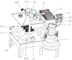
FIG. 1 is a schematic structural diagram of the present invention.
Fig. 2 is a schematic view of the internal structure of the present invention.
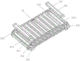
Fig. 3 is a schematic structural diagram of the conveying mechanism.
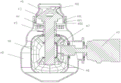
FIG. 4 is a cross-sectional view of the solids processing mechanism.
Fig. 5 is an exploded view of the solids handling mechanism.
Fig. 6 is a schematic view of the structure of the feed rod.
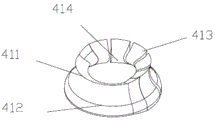
FIG. 7 is a schematic view of the structure of the mating ring.
Fig. 8 is a schematic structural diagram of the breaking mechanism.
Fig. 9 is a schematic structural view of the cutting mechanism.
Fig. 10 is a schematic view of the structure of the filter mechanism.
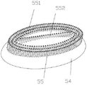
Fig. 11 is a schematic structural view of the exhaust joint.
Detailed Description
In order to make the invention more comprehensible, the following detailed description is given with reference to the accompanying drawings.
As shown in fig. 1 and 2, a kitchen waste treatment device comprises a frame 1, a case 2, a conveying mechanism 3, a solid treatment mechanism 4 and an oil-liquid separation mechanism 5; the top of frame 1 and the bottom fixed connection of quick-witted case 2, quick-witted case 2 top and bottom all are four prismatic table forms, and the left top of quick-witted case 2 and left bottom are provided with first liquid outlet 201 and second liquid outlet 203 respectively, all are provided with the lid 204 through threaded connection on first liquid outlet 201 and the second liquid outlet 203, and the diameter of first liquid outlet 201 is greater than the diameter of second liquid outlet 203, and first liquid outlet 201 can be salvaged out through opening the greasy dirt of lid 204 manual work with the top. The rear side wall of the upper part of the case 2 is also provided with an oil stain discharge pipeline 202, a vertical pipeline 21 is arranged in the case 2, the vertical pipeline 21 extends from the inside of the case 2 to the upper part of the top surface of the case 2, the top part of the vertical pipeline 21 is provided with a cover body 204 in threaded connection, the middle part of the vertical pipeline 21 is connected with a liquid discharge pipeline 22, the vertical pipeline 21 is communicated with the liquid discharge pipeline 22, the liquid discharge pipeline 22 extends from the middle part of the vertical pipeline 21 to the outside of the case 2, the liquid discharge pipeline 22 and the oil stain discharge pipeline 202 are provided with valve bodies, the top part of the right side of the case 2 is provided with a case cover, the case cover is provided with a handle convenient for a worker to take, and the right side wall of the case 2 is provided with a feeding pipeline 23; the top of machine case 2 is provided with hot plate 8 that is used for preventing the solidification of waste liquid, and hot plate 8 is 2, and sets up respectively on the front side and the right side at machine case 2 top.
As shown in fig. 3, the conveying mechanism 3 is disposed below the feeding duct 23, the conveying mechanism 3 includes a conveying belt 31, a conveying driving roller, a conveying driven roller and a conveying motor 34, the conveying belt 31, the conveying driving roller and the conveying driven roller are disposed in the cabinet 2, the conveying motor 34 is disposed outside the cabinet 2, the conveying motor 34 is fixedly disposed on the right side wall of the cabinet 2 through a motor bracket 35, the conveying motor 34 is connected with the conveying driving roller, the conveying driving roller is connected with the conveying driven roller through the conveying belt 31, the conveying driving roller includes a first driving gear 321, a second driving gear 322 and a first rotating shaft 323, the first driving gear 321 is connected with the rotating shaft of the conveying motor 34, the first driving gear 321 is connected with the second driving gear 322 through a first rotating shaft 323, the conveying driven roller includes a first driven gear 331, a second driven gear 332 and a second rotating shaft 333, the first driven gear 331 and the second driven gear 332 are connected through the second rotating shaft 333, the conveyer belt 31 is formed by connecting a plurality of conveying connecting plates 311 which are regularly arranged, each conveying connecting plate 311 is provided with a plurality of falling holes 312 which are regularly arranged and used for dripping waste liquid, two bearings 313 are arranged on two sides of each connecting plate 311, and one side bearing 313 of one connecting plate 311 is connected with the other side bearing 313 of the adjacent connecting plate 311 through a bearing connecting plate 314; the teeth of the first driving gear 321, the second driving gear 322, the first driven gear 331 and the second driven gear 332 are disposed in the gap between the bearing 313 and the adjacent bearing 313. The discharge end below of conveying mechanism 3 is provided with connects the flitch 36, and the discharge end that connects flitch 36 is provided with waste outlet 37, and waste outlet 37 passes through waste material feed hopper 6 with solid processing mechanism 4 and is connected, and waste material feed hopper 6 is located waste outlet 37's below, and waste material feed hopper's left side is provided with the air blower 9 that is used for clearing up the filter mechanism and prevents that the waste material from blockking up. The blower 9 is fixed on the side wall of the case 2 by a blower fixing frame. A filtering mechanism for limiting the volume of the waste passing through is arranged in the waste feeding funnel 6;
the rubbish gets into by charge-in pipeline 23, falls into on conveying mechanism 3, and rubbish divide into solid-state waste and liquid form waste liquid, and the waste liquid falls into the bottom of quick-witted case 2 by the space department on the hole that falls on the conveyer belt 31 and conveying mechanism 3, and the rubbish passes through conveyer belt 31 and transmits to receiving the flitch 36 on, by receiving the waste outlet 37 roll-off quick-witted case 2 of flitch 36 bottom, falls into in the rubbish feed hopper 6.
As shown in fig. 10, a filtering mechanism for limiting the volume of the waste passing through is arranged in the waste feeding hopper 6, and the filtering mechanism comprises a plurality of limiting plates 71, a gear ring 73, an adjusting plate 74, a gear ring seat 75 and a rotating pin 76, wherein the gear ring 73 is arranged on the gear ring seat 75, the gear ring 73 is rotatably connected with the gear ring seat 75, a mounting ring is arranged on the inner side of the gear ring seat 75, a plurality of gears 72 are respectively hinged on the mounting ring through the rotating pin 76, and the gears 72 are respectively meshed with the clamping teeth on the inner ring of the gear ring 73; the limiting plates 71 are arranged in a spiral manner, the limiting plates 71 are fixedly connected with the gear 72 respectively, the limiting plates 71 are arc-shaped, the outer ends of the limiting plates 71 are thinner than the inner ends of the limiting plates, the inner end of each limiting plate 71 is provided with a hook, the bottom of each limiting plate 71 is provided with an arc-shaped baffle, and each limiting plate 71 is provided with a plurality of limiting holes with different sizes and shapes; the adjusting plate 74 is fixedly connected with the outer part of the gear ring 73, the adjusting plate 74 is arc-shaped, an adjusting neutral gear convenient to move is arranged on the adjusting plate 74, and the adjusting plate 74 and the limiting plate 71 are arranged oppositely; the ring gear 73 is rotated by moving the regulating plate 74 and the restriction plate 71 completes the rotation contraction or the rotation expansion in the waste feed hopper 6.
When the wastes material passes through filtering mechanism, can control the size that the wastes material passed through limiting plate 71, through removing regulating plate 74, make ring gear 73 rotatory, the rotatory gear 72 that can drive the limiting plate 71 outer end of ring gear 73 is rotatory, and gear 72 swivelling movement can drive limiting plate 71 swivelling movement and accomplish shrink and open. Therefore, objects with relatively large volume are prevented from entering the solid processing mechanism 4 and can be directly taken out from the filtering mechanism, so that the abrasion and the use efficiency of the solid processing mechanism 4 can be prevented, and the service life of the solid processing mechanism 4 is prolonged.
The filtering mechanism can solve the problem that the inlet of the solid treatment mechanism 4 is blocked or the service life of the solid treatment mechanism 4 is shortened due to the fact that waste with overlarge volume enters the solid treatment mechanism 4. The filtering mechanism can control the volume of the passing waste, prevent the inlet of the solid treatment mechanism 4 from being blocked and increase the service efficiency of the solid treatment mechanism 4, better protect the solid treatment mechanism 4 and prolong the service life of the solid treatment mechanism 4.
As shown in fig. 4 and 5, the solids processing mechanism 4 includes a feed housing 41, an outer housing 42, a feed bar 43, a breaking mechanism 44, a cutting mechanism 45, a deflector shield 48, and a motor 49. The lower part of the feeding shell 41 is connected with the upper part of the outer shell 42, the outer wall of the feeding shell 41 is provided with a connecting arm 403 for mounting screws, the bottom of the feeding shell 41 is provided with a first convex ring 401 and a second convex ring 402, the inner wall of the upper part of the outer shell 42 is provided with a third convex ring 421, the upper part of the outer shell 42 is sleeved on the bottom of the feeding shell 41, the third convex ring 421 is arranged between the first convex ring 401 and the second convex ring 402 and has a space moving up and down, the outer wall of the outer shell 42 is provided with a first convex block 423 fixedly connected with the feeding shell 41 through screws, the screws are provided with springs for controlling the third convex ring 421 to move up and down, the outer wall of one side of the outer shell 42 is provided with a connecting head 422, the connecting head 422 is provided with through holes for mounting an output shaft of a motor 49, a third bearing is arranged between the motor 49 and the outer shell 42, the first convex block 402 is fixedly connected with the outer shell 42 through the third bearing, the bottom of the outer shell 42 is provided with a blanking port. A cavity for installing the diversion protection cover 48 is formed in the outer shell 42, a diversion channel is formed between the outer shell 42 and the diversion protection cover 48, the diversion protection cover 48 is arranged on the lower portion of the cavity of the outer shell 42, the top of the diversion protection cover 48 is fixedly connected with a first bearing on the cutting mechanism 45, and a round hole corresponding to a through hole in the connector 422 is formed in the side wall of the diversion protection cover 48. The output shaft passes through connector 422 and water conservancy diversion safety cover 48 lateral wall, the tip fixed connection main drive conical gear 47 of output shaft, be provided with the annular groove of installation second bearing on the main drive conical gear 47, water conservancy diversion safety cover 48 passes through second bearing and main drive conical gear 47 fixed connection, main drive conical gear 47 sets up under first driven conical gear 452 and meshes with first driven conical gear 452 mutually, main drive conical gear 47 below is equipped with second driven conical gear 46, second driven conical gear 46 fixed connection is at the lower tip of transmission shaft 432, second driven conical gear 46 meshes with main drive conical gear 47 mutually. The number of teeth 452 of the first driven bevel gear is greater than the number of teeth of the second driven bevel gear 46. The first driven bevel gear 451, the second driven bevel gear 46 and the main transmission bevel gear 47 are all arranged in the diversion protection cover 48, and the bottom of the diversion protection cover 48 is provided with an opening for installing the first driven bevel gear 452, the second driven bevel gear 46 and the main transmission bevel gear 47.
As shown in fig. 6 and 7, a matching ring 411 is arranged in the feeding shell 41, the matching ring 411 is made of an elastic material, a convex surface 414 matched with the feeding rod 43 is arranged on the matching ring 411, an upper end inner ring of the matching ring 411 is flared, and a lower end inner ring of the matching ring 411 is spiral and can screw garbage into the outer shell 42. The mating ring 411 is divided into a continuous portion 412 and a neutral portion 413 provided with several neutral positions. The feeding rod 43 is divided into an upper part and a lower part, the upper part is a mushroom-shaped material pushing head 431, the lower part is a transmission shaft 432, and the shape of the material pushing head 431 is matched with the matching ring convex surface 414 to screw the garbage into the outer shell 42.
As shown in fig. 8, a scattering mechanism 44 is provided at an upper portion of the driving shaft 432, the scattering mechanism 44 includes a scattering ring 441, a scattering blade 442, and a fixing rod 443, the scattering ring 441 is fixedly provided on the driving shaft 432, the fixing rod 443 is radially fixed to an outer wall of the scattering ring 441, and the scattering blade 442 is fixed to the fixing rod 443. The number of the fixing rods 443 is 3, the included angle between any two adjacent fixing rods 443 is the same, each fixing rod 443 is provided with 3 scattering blades 442, and the 3 scattering blades 442 are arranged in parallel in the transverse direction.
As shown in fig. 9, a cutting mechanism 45 is disposed below the scattering mechanism 44, the cutting mechanism 45 includes a cutting ring 451, cutting blades 453 and a first driven bevel gear 452, the cutting ring 451 is disposed on the transmission shaft 432, the cutting blades 453 are spirally disposed on the outer wall of the cutting ring 451, the cutting blades 453 are 3, the included angle between any two adjacent cutting blades 453 is the same, the bending direction of the cutting blades 453 is the same as the rotating direction, the first driven bevel gear 452 is fixedly disposed below the cutting ring 451, and an annular groove for mounting the first bearing 40 is disposed between the cutting ring 451 and the first driven bevel gear 452.
When breaking up cutting device and using, the wastes material gets into the feed inlet of feeding casing 41, rotate through motor 49, drive final drive conical gear 47, final drive conical gear 47 drives first driven conical gear 452 and the driven conical gear 46 of second, the driven conical gear 46 of second drives the rotation of feed rod 43, pivoted feed rod 43 and cooperation ring 411's cooperation, it breaks up the mechanism 44 to change over into the wastes material to break up to the wastes material, break up the wastes material earlier, more abundant quilt cuts, the efficiency of cutting is better, reentrant cutting mechanism 45, with rubbish cutting, after the cutting, rubbish enters into the water conservancy diversion passageway, the blanking mouth that follows shell body 42 bottom through the water conservancy diversion passageway drops out.
The solid treatment means 4 solves the problems that waste not treated is blocked in sewer pipes due to excessive particles and the waste is difficult to decompose. The solid treatment mechanism 4 is matched with the mushroom-shaped material pushing head 431 through the matching ring 411, so that the hard extrusion of the garbage and the device can be reduced, and the service life is prolonged. Through breaking up earlier cutting again, can prevent the cutting of rubbish hard, break up earlier, can make more abundant of cutting next, improve cutting efficiency and cutting performance.
As shown in fig. 1, 2 and 11, the oil-liquid separation mechanism 5 includes a control box support 51, an oil-liquid separation control box 52 and a separation pipeline 53, the oil-liquid separation control box 52 is disposed on the top of the chassis 2, an air outlet of the oil-liquid separation control box 52 is connected to the separation pipeline 53, the separation pipeline 53 extends from the outside of the chassis 2 to the inside of the chassis 2, the end of the separation pipeline 53 is closed, the separation pipeline 53 inside the chassis 2 is connected to a plurality of exhaust joints 54, the exhaust joints 54 are semi-arc-shaped, each exhaust joint 54 is provided with a plurality of exhaust tubules 55, and air outlets of the exhaust tubules 55 face upward to exhaust air upward. The exhaust narrow tube 55 is divided into an elliptical narrow tube 551 and a linear narrow tube 552, the linear narrow tube 552 is provided at the center of the top surface of the exhaust joint 54, the elliptical narrow tube 551 is provided in the outer circumferential direction of the top surface of the exhaust joint 54, and the height of the linear narrow tube 552 is higher than that of the elliptical narrow tube 551. The oil-liquid separating mechanism 5 separates liquid from oil stain, the liquid is discharged from the liquid discharge pipe 22, and the oil stain is discharged from the oil stain discharge pipe 202. The oil stain can be fished out from the top vertical pipeline 21 and the first liquid outlet 201, and the liquid can be discharged from the bottom second liquid outlet 203.
The oil-liquid separation mechanism 5 can upwards exhaust, upwards push the oil stain to make the upper layer of the whole solution be the oil stain, the lower layer is waste liquid, the waste liquid of the lower layer flows out of the bottom of the liquid discharge pipeline 22 or the bottom of the case 2, and the oil stain is fished out of the top of the vertical pipeline 21 or the case 2.
The oil-liquid separation mechanism 5 solves the problem that the oil stain and the waste liquid are mixed and flow to a sewer pipeline to pollute the environment and water quality. The oil-liquid separation mechanism 5 separates liquid from oil stains and enables the liquid and the oil stains to flow out through different pipelines, and waste liquid is subjected to classification treatment, so that water pollution can be prevented, and the environment is protected.
A step of garbage treatment:
(1) feeding garbage: the solid, liquid and oil dirt mixed garbage is fed through a feeding pipeline 23;
(2) solid-liquid separation: the solid garbage is conveyed to the solid treatment mechanism 4 through the conveying mechanism 3 for treatment, and the liquid falls into the bottom of the case 2 through the falling holes 312 and the gaps in the conveying mechanism 3;
(3) solid waste treatment: the solid garbage enters the solid treatment mechanism 4 through the filtering mechanism, is scattered and cut and then is discharged;
(4) oil-liquid separation: the waste liquid is divided into two layers by the oil-liquid separation mechanism 5, the upper layer is oil stain, and the lower layer is liquid;
(5) waste liquid treatment: the lower layer of liquid is discharged through the liquid discharge pipe 22 and the upper layer of oil is discharged through the oil discharge pipe 202.
When the whole system uses, surplus waste liquid in kitchen and wastes material get into in the feed pipeline 23 in the lump, and the bottom of quick-witted case 2 falls into in the waste liquid is by the lower hole 312 on conveying mechanism 3 and the space, and the waste liquid is more and more back, through fluid separating mechanism 5, with gas input machine incasement 2 in, makes greasy dirt and liquid separation, and the greasy dirt is in the upper strata, and liquid is in the lower floor, and the greasy dirt is fished out through the top of quick-witted case 2, and liquid discharges through the pipeline of quick-witted case 2 lateral part and flows. The waste falls into waste feed hopper 6 through material receiving plate 36 by conveying mechanism 3, enters solid processing mechanism 4 through filtering mechanism 6, breaks up the waste and cuts the waste and then flows out.
In conclusion, the conveying mechanism 3 can separate the solid and the liquid for treatment, and prevent the solid and the liquid from being introduced into a sewer together to pollute the water quality and the environment; the oil-liquid separation mechanism 5 can separate and treat oil stains and waste liquid in the liquid, so that pollution is reduced; the solid treatment mechanism 4 can better fully cut the garbage by scattering and then cutting, so that the cutting efficiency and the cutting performance are improved; through the matching of the elastic matching ring and the mushroom-shaped material pushing head, hard extrusion of hard garbage and the device can be prevented, and the service life of the equipment is ensured; the filtering mechanism can prevent overlarge objects from blocking the sewer pipeline.
Claims (9)
1. A kitchen waste treatment device comprises a rack (1), a case (2), a conveying mechanism (3), a solid treatment mechanism (4) and an oil-liquid separation mechanism (5); the case (2) is fixedly arranged on the rack (1), and a feeding pipeline (23) is arranged on the right side wall of the case (2); the conveying mechanism (3) is arranged below the feeding pipeline (23) and is used for conveying solid garbage and separating the solid garbage from liquid garbage; a material receiving plate (36) is arranged below the discharge end of the conveying mechanism (3), a waste outlet (37) is arranged at the discharge end of the material receiving plate (36), the waste outlet (37) is connected with the solid treatment mechanism (4) through a waste feeding funnel (6), and a filtering mechanism for limiting the volume of waste passing through is arranged in the waste feeding funnel (6); the oil-liquid separation mechanism (5) is used for separating oil stains from liquid;
the filtering mechanism is characterized by comprising a plurality of limiting plates (71), a gear ring (73), an adjusting plate (74), a gear ring seat (75) and a rotating pin (76), wherein the gear ring (73) is arranged on the gear ring seat (75), the gear ring (73) is rotatably connected with the gear ring seat (75), a mounting ring is arranged on the inner side of the gear ring seat (75), a plurality of gears (72) are respectively hinged on the mounting ring through the rotating pin (76), and the gears (72) are respectively meshed with clamping teeth of the inner ring of the gear ring (73); the limiting plates (71) are arranged in a spiral manner, the limiting plates (71) are respectively fixedly connected with the gear (72), the limiting plates (71) are arc-shaped, the outer ends of the limiting plates (71) are thinner than the inner ends of the limiting plates, the inner end of each limiting plate (71) is provided with a hook, the bottom of each limiting plate (71) is provided with an arc-shaped baffle, and each limiting plate (71) is provided with a plurality of limiting holes with different sizes and shapes; the adjusting plate (74) is fixedly connected with the outer part of the gear ring (73), the adjusting plate (74) is arc-shaped, an adjusting neutral gear convenient to move is arranged on the adjusting plate (74), and the adjusting plate (74) and the limiting plate (71) are oppositely arranged; the ring gear (73) is rotated by moving the adjusting plate (74), and the limiting plate (71) completes the rotary contraction or the rotary expansion in the waste feeding hopper (6).
2. The kitchen waste treatment equipment according to claim 1, wherein a vertical pipeline (21) is arranged in the case (2), the vertical pipeline (21) extends from the inside of the case (2) to the position above the top surface of the case (2), a liquid discharge pipeline (22) is connected to the middle of the vertical pipeline (21), the vertical pipeline (21) is communicated with the liquid discharge pipeline (22), the liquid discharge pipeline (22) extends from the middle of the vertical pipeline (21) to the outside of the case (2), and an oil stain discharge pipeline (202) is arranged on the side wall of the upper part of the case (2); a first liquid outlet (201) and a second liquid outlet (203) are respectively arranged at the top center of the case (2) and the bottom center of the case (2), and cover bodies (204) in threaded connection are respectively arranged at the tops of the first liquid outlet (201), the second liquid outlet (203) and the vertical pipeline (21); the oil stain discharge pipeline (202) and the liquid discharge pipeline (22) are both provided with valve bodies.
3. The kitchen waste treatment equipment according to claim 1, wherein the conveying mechanism (3) comprises a conveying belt (31), a conveying driving roller, a conveying driven roller and a conveying motor (34), the conveying belt (31), the conveying driving roller and the conveying driven roller are arranged in the cabinet (2), the conveying motor (34) is arranged outside the cabinet (2), the conveying motor (34) is fixedly arranged on the right side wall of the cabinet (2) through a motor bracket (35), the conveying motor (34) is connected with the conveying driving roller, the conveying driving roller is connected with the conveying driven roller through the conveying belt (31), and the conveying belt (31) is provided with a plurality of waste liquid holes for dropping waste liquid; the conveying driving roller comprises a first driving gear (321), a second driving gear (322) and a first rotating shaft (323), the first driving gear (321) is connected with a rotating shaft of a conveying motor (34), the first driving gear (321) is connected with the second driving gear (322) through the first rotating shaft (323), the conveying driven roller comprises a first driven gear (331), a second driven gear (332) and a second rotating shaft (333), the first driven gear (331) is connected with the second driven gear (332) through the second rotating shaft (333), a conveying belt (31) is formed by connecting a plurality of conveying connecting plates (311) which are regularly arranged, a plurality of falling holes (312) which are regularly arranged and used for dripping waste liquid are formed in each conveying connecting plate (311), two bearings (313) are arranged on two sides of each connecting plate (311), one side bearing (313) of one connecting plate (311) is connected with the other side bearing (313) of the adjacent connecting plate (311) through a bearing connecting plate (314) ) Connecting; the teeth of the first driving gear (321), the second driving gear (322), the first driven gear (331) and the second driven gear (332) are all arranged in a gap between the bearing (313) and the adjacent bearing (313).
4. The kitchen waste treatment device according to claim 1, wherein said solids treatment means (4) comprises a feed housing (41), an outer housing (42), a feed rod (43), a breaking means (44), a cutting means (45), a deflector shield (48) and a motor (49); the feeding shell (41) is arranged above the outer shell (42), a matching ring (411) is arranged in the feeding shell (41), and a convex surface (414) matched with the feeding rod (43) is arranged on the matching ring (411); the feeding rod (43) is divided into an upper part and a lower part, the upper part is a mushroom-shaped material pushing head (431), the shape of the material pushing head (431) is matched with the convex surface (414) of the matching ring to screw the garbage into the outer shell (42), and the lower part is a transmission shaft (432); the upper part of the transmission shaft (432) is provided with a scattering mechanism (44), the scattering mechanism (44) comprises a scattering ring (441), a scattering blade (442) and a fixing rod (443), the scattering ring (441) is fixedly arranged on the transmission shaft (432), the fixing rod (443) is radially fixed on the outer wall of the scattering ring (441), and the scattering blade (442) is fixed on the fixing rod (443); a cutting mechanism (45) is arranged below the scattering mechanism (44), the cutting mechanism (45) comprises a cutting ring (451), a first driven bevel gear (452) and cutting blades (453), the cutting ring (451) is rotatably sleeved on the transmission shaft (432), a plurality of cutting blades (453) are arranged on the outer wall of the cutting ring (451), and the first driven bevel gear (452) is fixedly arranged below the cutting ring (451); a cavity for installing a flow guide protection cover (48) is arranged at the lower part of the outer shell (42), the flow guide protection cover (48) is fixedly arranged in the cavity, a flow guide channel is formed between the outer shell (42) and the flow guide protection cover (48), and a discharge hole is formed in the bottom of the outer shell (42); the cutting ring (451) penetrates through the top of the diversion protection cover (48), and the first driven conical gear (452) is arranged in the diversion protection cover (48); outer shell (42) one side outer wall on be provided with connector (422), be provided with the through-hole on connector (422), motor (49) are fixed to be set up on connector (422), the output shaft of motor (49) passes the inside that the through-hole extends to water conservancy diversion safety cover (48), and water conservancy diversion safety cover (48) are provided with the output shaft looks transmission connection of main drive conical gear (47) and motor (49), main drive conical gear (47) upper portion meshes with first driven conical gear (452) mutually, transmission shaft (432) pass water conservancy diversion safety cover (48) top and extend to the lower part of water conservancy diversion safety cover (48), be provided with driven conical gear of second (46) and transmission shaft (432) and be connected mutually in water conservancy diversion safety cover (48), driven conical gear of second (46) meshes with main drive conical gear (47) mutually.
5. The kitchen waste treatment equipment according to claim 4, characterized in that the outer wall of the feeding shell (41) is provided with a connecting arm (403) for mounting a screw, the bottom of the feeding shell (41) is provided with a first convex ring (401) and a second convex ring (402), the inner wall of the upper part of the outer shell (42) is provided with a third convex ring (421), the upper part of the outer shell (42) is sleeved on the bottom of the feeding shell (41), the third convex ring (421) is mounted between the first convex ring (401) and the second convex ring (402) and has a space moving up and down, the outer wall of the outer shell (42) is provided with a first convex block (423) fixedly connected with the feeding shell (41) through a screw, and the screw is provided with a spring for controlling the third convex ring (421) to move up and down; the matching ring (411) is made of elastic materials, and the matching ring (411) is divided into a continuous part (412) and a neutral part (413) provided with a plurality of neutral positions; the upper end inner ring of the matching ring (411) is flared, and the lower end inner ring of the matching ring (411) is spiral and can screw garbage into the outer shell (42); a rotary extrusion space is formed between the outer walls of the two sides of the material pushing head (431) and the inner ring at the lower part of the matching ring (411), and the top of the material pushing head (431) is higher than the convex surface (414) of the matching ring.
6. The kitchen waste treatment device according to claim 1, wherein the oil-liquid separation mechanism (5) comprises a control box support (51), an oil-liquid separation control box (52) and a separation pipeline (53), the oil-liquid separation control box (52) is arranged at the top of the cabinet (2), an air outlet of the oil-liquid separation control box (52) is connected with the separation pipeline (53), the separation pipeline (53) extends into the cabinet (2) from the outside of the cabinet (2), the tail end of the separation pipeline (53) is closed, the separation pipeline (53) in the cabinet (2) is connected with a plurality of exhaust connectors (54), each exhaust connector (54) is provided with a plurality of exhaust tubules (55), and the air outlet of each exhaust tubule (55) faces upwards to exhaust air upwards.
7. The kitchen garbage disposal apparatus as recited in claim 6, wherein said exhaust joint (54) is a semicircular arc, said exhaust tubule (55) is divided into an elliptical tubule (551) and a linear tubule (552), said linear tubule (552) is disposed in the middle of the top surface of said exhaust joint (54), said elliptical tubule (551) is disposed in the circumferential direction of the outer circumference of the top surface of said exhaust joint (54), and the height of said linear tubule (552) is higher than the height of said elliptical tubule (551).
8. The kitchen waste treatment device according to claim 1, characterized in that the top of the cabinet (2) is provided with a heating plate (8) for preventing waste liquid from solidifying; one side of the waste feeding hopper (6) is connected with a filtering mechanism for cleaning and a blower (9) for preventing waste from being blocked.
9. A method for treating kitchen waste, characterized in that it uses the apparatus of claim 1, successively following the steps:
feeding garbage: feeding the solid, liquid and oil-contaminated mixed garbage through a feeding pipeline;
solid-liquid separation: conveying the solid garbage to a solid treatment mechanism for treatment through a conveying mechanism, and allowing liquid to fall into the bottom of the case through falling holes and gaps in the conveying mechanism;
solid waste treatment: the solid garbage enters a solid treatment mechanism through a filtering mechanism, is scattered and cut and then is discharged;
oil-liquid separation: the waste liquid is divided into two layers by an oil-liquid separation mechanism, the upper layer is oily dirt, and the lower layer is liquid;
waste liquid treatment: the liquid on the lower layer is discharged through a liquid discharge pipeline, and the oil stain on the upper layer is discharged through an oil stain discharge pipeline.
Priority Applications (1)
| Application Number | Priority Date | Filing Date | Title |
|---|---|---|---|
| CN201910017969.2A CN109758825B (en) | 2019-01-09 | 2019-01-09 | Kitchen waste treatment equipment and method thereof |
Applications Claiming Priority (1)
| Application Number | Priority Date | Filing Date | Title |
|---|---|---|---|
| CN201910017969.2A CN109758825B (en) | 2019-01-09 | 2019-01-09 | Kitchen waste treatment equipment and method thereof |
Publications (2)
| Publication Number | Publication Date |
|---|---|
| CN109758825A CN109758825A (en) | 2019-05-17 |
| CN109758825B true CN109758825B (en) | 2021-10-08 |
Family
ID=66452788
Family Applications (1)
| Application Number | Title | Priority Date | Filing Date |
|---|---|---|---|
| CN201910017969.2A Active CN109758825B (en) | 2019-01-09 | 2019-01-09 | Kitchen waste treatment equipment and method thereof |
Country Status (1)
| Country | Link |
|---|---|
| CN (1) | CN109758825B (en) |
Families Citing this family (1)
| Publication number | Priority date | Publication date | Assignee | Title |
|---|---|---|---|---|
| CN114273354B (en) * | 2021-12-18 | 2023-05-02 | 深圳市雄鹰环境产业有限公司 | Kitchen garbage separator |
Citations (8)
| Publication number | Priority date | Publication date | Assignee | Title |
|---|---|---|---|---|
| JPH10235331A (en) * | 1997-02-24 | 1998-09-08 | Sanyo Electric Co Ltd | Garbage treatment apparatus |
| US6372129B1 (en) * | 1999-05-19 | 2002-04-16 | Steven R. Moody | Cleaning grease and oils from waste streams |
| CN206747234U (en) * | 2017-03-06 | 2017-12-15 | 内江市润宏环保科技有限公司 | A kind of Kitchen garbage disposal device |
| CN107792563A (en) * | 2017-10-27 | 2018-03-13 | 无锡凹凸自动化科技有限公司 | A kind of garbage settles sorter |
| CN107899705A (en) * | 2017-12-11 | 2018-04-13 | 天津唯楚科技有限公司 | A kind of garbage is dehydrated deoiler |
| CN108793466A (en) * | 2018-06-21 | 2018-11-13 | 任智宇 | A kind of kitchen waste water processing method |
| CN109056926A (en) * | 2018-09-19 | 2018-12-21 | 杨立撒 | A kind of feeding device and kitchen waste treater of kitchen waste treater |
| CN109056927A (en) * | 2018-09-19 | 2018-12-21 | 杨立撒 | Garbage treatment device |
-
2019
- 2019-01-09 CN CN201910017969.2A patent/CN109758825B/en active Active
Patent Citations (8)
| Publication number | Priority date | Publication date | Assignee | Title |
|---|---|---|---|---|
| JPH10235331A (en) * | 1997-02-24 | 1998-09-08 | Sanyo Electric Co Ltd | Garbage treatment apparatus |
| US6372129B1 (en) * | 1999-05-19 | 2002-04-16 | Steven R. Moody | Cleaning grease and oils from waste streams |
| CN206747234U (en) * | 2017-03-06 | 2017-12-15 | 内江市润宏环保科技有限公司 | A kind of Kitchen garbage disposal device |
| CN107792563A (en) * | 2017-10-27 | 2018-03-13 | 无锡凹凸自动化科技有限公司 | A kind of garbage settles sorter |
| CN107899705A (en) * | 2017-12-11 | 2018-04-13 | 天津唯楚科技有限公司 | A kind of garbage is dehydrated deoiler |
| CN108793466A (en) * | 2018-06-21 | 2018-11-13 | 任智宇 | A kind of kitchen waste water processing method |
| CN109056926A (en) * | 2018-09-19 | 2018-12-21 | 杨立撒 | A kind of feeding device and kitchen waste treater of kitchen waste treater |
| CN109056927A (en) * | 2018-09-19 | 2018-12-21 | 杨立撒 | Garbage treatment device |
Also Published As
| Publication number | Publication date |
|---|---|
| CN109758825A (en) | 2019-05-17 |
Similar Documents
| Publication | Publication Date | Title |
|---|---|---|
| CN109868799B (en) | Gate for river course with filter interception function | |
| CA2114241C (en) | Garbage disposal system | |
| CN108640337B (en) | Working method of multistage separation device for solid waste in sewage | |
| CN104107828A (en) | High-efficiency garbage processor | |
| CN112794487B (en) | Breed sewage self-loopa clarification plant | |
| CN109758825B (en) | Kitchen waste treatment equipment and method thereof | |
| CN109701699B (en) | Filtering mechanism and kitchen waste treatment equipment | |
| CN111790747A (en) | Can strengthen soil prosthetic devices of soil repair effect | |
| CN109675364B (en) | Kitchen waste treatment equipment | |
| CN210700544U (en) | A quick reducing mechanism for agricultural product processing | |
| KR101113209B1 (en) | Food waste reduction apparatus | |
| CN116673298A (en) | Domestic garbage treatment device for preventing and treating environmental pollution | |
| CN109940785B (en) | Oil refining production line is retrieved to abandonment tire | |
| CN211251435U (en) | Kitchen waste treatment device | |
| CN109534529A (en) | A kind of sewage disposal device for environmental protection | |
| CN214234348U (en) | Packaging device for construction waste | |
| CN112142285B (en) | Ecological environment-friendly septic tank | |
| CN210787580U (en) | Dust protected extract reducing mechanism | |
| CN112356756A (en) | Prevent blockking up sewage rapid treatment car | |
| CN110485522A (en) | Sundries shredder | |
| CN111905887A (en) | Intelligent organic garbage treatment device and method | |
| CN110735470A (en) | garbage filtering and separating device and garbage disposal system | |
| CN220310919U (en) | Fine rolling screen separating device for solid dangerous waste contaminated soil | |
| CN219231566U (en) | Sewage treatment grille | |
| CN218794246U (en) | Stone material processing effluent treatment plant |
Legal Events
| Date | Code | Title | Description |
|---|---|---|---|
| PB01 | Publication | ||
| PB01 | Publication | ||
| SE01 | Entry into force of request for substantive examination | ||
| SE01 | Entry into force of request for substantive examination | ||
| TA01 | Transfer of patent application right | ||
| TA01 | Transfer of patent application right |
Effective date of registration: 20210917 Address after: 224000 Room 303 (d), building D5, Yancheng hi tech Pioneer Park, No. 9, Huarui Middle Road, Yanlong street, Yandu District, Yancheng City, Jiangsu Province Applicant after: Jiangsu new space industry incubation Co.,Ltd. Address before: No. 999, Huahe street, dinglan street, Jianggan District, Hangzhou City, Zhejiang Province, 310021 Applicant before: Yang Lisa |
|
| GR01 | Patent grant | ||
| GR01 | Patent grant |