CN1097532C - High pressure resistant initiator with integral metal oxide varistor for electro-static discharge protection - Google Patents
High pressure resistant initiator with integral metal oxide varistor for electro-static discharge protection Download PDFInfo
- Publication number
- CN1097532C CN1097532C CN97110118A CN97110118A CN1097532C CN 1097532 C CN1097532 C CN 1097532C CN 97110118 A CN97110118 A CN 97110118A CN 97110118 A CN97110118 A CN 97110118A CN 1097532 C CN1097532 C CN 1097532C
- Authority
- CN
- China
- Prior art keywords
- body skin
- high pressure
- pressure resistant
- glass
- metal oxide
- Prior art date
- Legal status (The legal status is an assumption and is not a legal conclusion. Google has not performed a legal analysis and makes no representation as to the accuracy of the status listed.)
- Expired - Fee Related
Links
Images


Classifications
-
- B—PERFORMING OPERATIONS; TRANSPORTING
- B60—VEHICLES IN GENERAL
- B60R—VEHICLES, VEHICLE FITTINGS, OR VEHICLE PARTS, NOT OTHERWISE PROVIDED FOR
- B60R21/00—Arrangements or fittings on vehicles for protecting or preventing injuries to occupants or pedestrians in case of accidents or other traffic risks
- B60R21/02—Occupant safety arrangements or fittings, e.g. crash pads
- B60R21/16—Inflatable occupant restraints or confinements designed to inflate upon impact or impending impact, e.g. air bags
- B60R21/26—Inflatable occupant restraints or confinements designed to inflate upon impact or impending impact, e.g. air bags characterised by the inflation fluid source or means to control inflation fluid flow
- B60R21/264—Inflatable occupant restraints or confinements designed to inflate upon impact or impending impact, e.g. air bags characterised by the inflation fluid source or means to control inflation fluid flow using instantaneous generation of gas, e.g. pyrotechnic
- B60R21/2644—Inflatable occupant restraints or confinements designed to inflate upon impact or impending impact, e.g. air bags characterised by the inflation fluid source or means to control inflation fluid flow using instantaneous generation of gas, e.g. pyrotechnic using only solid reacting substances, e.g. pellets, powder
-
- B—PERFORMING OPERATIONS; TRANSPORTING
- B60—VEHICLES IN GENERAL
- B60R—VEHICLES, VEHICLE FITTINGS, OR VEHICLE PARTS, NOT OTHERWISE PROVIDED FOR
- B60R21/00—Arrangements or fittings on vehicles for protecting or preventing injuries to occupants or pedestrians in case of accidents or other traffic risks
- B60R21/02—Occupant safety arrangements or fittings, e.g. crash pads
- B60R21/16—Inflatable occupant restraints or confinements designed to inflate upon impact or impending impact, e.g. air bags
-
- F—MECHANICAL ENGINEERING; LIGHTING; HEATING; WEAPONS; BLASTING
- F42—AMMUNITION; BLASTING
- F42B—EXPLOSIVE CHARGES, e.g. FOR BLASTING, FIREWORKS, AMMUNITION
- F42B3/00—Blasting cartridges, i.e. case and explosive
- F42B3/10—Initiators therefor
- F42B3/12—Bridge initiators
- F42B3/13—Bridge initiators with semiconductive bridge
-
- F—MECHANICAL ENGINEERING; LIGHTING; HEATING; WEAPONS; BLASTING
- F42—AMMUNITION; BLASTING
- F42B—EXPLOSIVE CHARGES, e.g. FOR BLASTING, FIREWORKS, AMMUNITION
- F42B3/00—Blasting cartridges, i.e. case and explosive
- F42B3/10—Initiators therefor
- F42B3/18—Safety initiators resistant to premature firing by static electricity or stray currents
- F42B3/188—Safety initiators resistant to premature firing by static electricity or stray currents having radio-frequency filters, e.g. containing ferrite cores or inductances
-
- B—PERFORMING OPERATIONS; TRANSPORTING
- B60—VEHICLES IN GENERAL
- B60R—VEHICLES, VEHICLE FITTINGS, OR VEHICLE PARTS, NOT OTHERWISE PROVIDED FOR
- B60R21/00—Arrangements or fittings on vehicles for protecting or preventing injuries to occupants or pedestrians in case of accidents or other traffic risks
- B60R21/02—Occupant safety arrangements or fittings, e.g. crash pads
- B60R21/16—Inflatable occupant restraints or confinements designed to inflate upon impact or impending impact, e.g. air bags
- B60R21/26—Inflatable occupant restraints or confinements designed to inflate upon impact or impending impact, e.g. air bags characterised by the inflation fluid source or means to control inflation fluid flow
- B60R2021/26029—Ignitors
Landscapes
- Engineering & Computer Science (AREA)
- General Engineering & Computer Science (AREA)
- Mechanical Engineering (AREA)
- Physics & Mathematics (AREA)
- Fluid Mechanics (AREA)
- Air Bags (AREA)
- Multi-Conductor Connections (AREA)
Abstract
A resistant initiator for an automobile passenger restraint system which includes a shell casing (10) having an upper chamber (14) and a lower chamber (12). Contact pins (36) connect the initiator to a mating electrical connector of a vehicle. A metal oxide varistor (30) disposed in the shell casing provides electrostatic discharge and EMI/RFI protection for the initiator. A glass to metal seal header (40) is formed in the shell casing and includes an integrated circuit (46) for igniting the pyrotechnic material disposed in a charge holder (48) attached to the shell casing.
Description
The application relates to the examination U.S. Patent application of the 08/456th, No. 257 " the detonator inflation pump socket pins packing ring with the metal oxide varistor that is used for electrostatic discharge protective " by name; And U.S. Patent application in the examination of the 08/574th, No. 426 " the inflation pump detonator with Zener diode electrostatic discharge protective " by name, these two patents have all transferred cessionary of the present invention.
The present invention relates to a kind of electric initiation device or detonator that is used for car occupant security personnel electric system, relate in particular to a kind of detonator that comprises the metal oxide varistor that is used for electric initiation device electrostatic protection.
As everyone knows, in prior art, use a kind of inflatable passenger's security system that is used to protect car occupant.This security system comprises an air bag that the retort of gas generator or inflation pump is housed and is in non-inflated state.Gas generator produces gas in response to collision, airbag aeration is made it expansion, with the protection car occupant.
Be used for the inflation pump of the passive security system of automobile or the electric initiation device (EED) of other device a kind of pyro technical detonator of needs or operation inflation pump.In order to start gas generator or inflation pump, the electric initiation device takes fire the material in the gas generator.The inflation pump detonator is linked one and is arranged near the detonator or the impact microphone of automobile remote locations.
In operation, impact microphone transmits electric signal to detonator.Detonator is lighted in ignition chamber, and the container that comprises the fire lighter material is broken, and this material is the compound of carbon and nitre normally.Detonator comprises a pair of parallel electric pin (pin) that separates, and they are at one end linked to each other by the bridging plug of imbedding pyrotechnic material.Produce very hot flame during the pyrotechnic material burning, light and be included in generation of gas bead solid-state in the combustion chamber.These beads are emitted nitrogen, and nitrogen is through diffuser chamber and enter the protection air bag that is used to protect car occupant.
The denominator of electric initiation device (EED) is that bridging plug has sensivity to the energy that do not need from external environmental source, may cause improper use or " not igniting " of detonator.The N/R energy can be that Electrostatic Discharge, electromagnetic radiation disturb (EMI) or RF interference (RFI), but is not limited to these.Here will be called the EMI/RFI protection to the protection of this type of emittance of antagonism.
A prior art measure that overcomes EMI/RFI danger relates to use and directly is placed on the indoor ferrite bead of detonator.Ferrite bead absorbs external energy, arrives bridging plug to prevent energy.See the 4th, 306, No. 499 US Patent of Holmes, this patent has transferred cessionary of the present invention.
The problem of using the electric initiation device of Holmes is that the EMI/RFI protection is directly placed device size and manufacturing cost and the time of having increased in the EED zone.In addition, the maker of gas generator is restricted to special EED design.
Another measure is a general-duty fuse primer joint, and it comprises that one surrounds the ferrite bead of EED electric terminal.See the 5th, 200,574 and 5,241, No. 910 US Patent of people such as Cunningham, these two patents have transferred cessionary of the present invention.People such as Cunningham have disclosed a kind of universal joint of the EMI/RFI of comprising protection, and it is fixed in the gas generator always.Ferrite bead is the inducer of an obstruction electric current transient change in essence.
Another problem of known inflation pumping devices is that detonator (EED) twists in the base of inflation pump.If do badly, this curls and handles regular meeting's damage detonator.
Disclosed a kind of electric initiation device in the 4th, 103, No. 619 US Patent, wherein Zhuan Zhi contact pin glass sealing, and provide durable shunt to avoid the influence of external energy with the protection bridgt circuit.A shortcoming of durable shunt is that the part energy that offers detonator during use is divided to ground, so the gross energy that in fact needs required energy when not establishing durable shunt is more.
Disclosed a kind of firing unit that ferrite sleeve pipe (EMI/RFI) and electrostatic discharge disc (ESD) have been installed in the 4th, 422, No. 381 US Patent.The electrostatic discharge disc is according to being used for " spark gap " method of esd protection, and its purposes is generally limited to the static discharge voltage of specific type, promptly generally greater than 25,000 volts vdc.The present invention has utilized and can make esd protection be applicable to the metal oxide varistor of wideer voltage level range by changing the rheostat size.The present invention is designed to any external vdc that exceeds 500 volts is diverted to ground.
Fig. 1-6 has disclosed the detonator of various prior arts.Fig. 1 has disclosed a kind of low-cost firing unit of the ICI Explosives manufacturing in Ta Makua city, Pennsyivania, and it has installed the spark gap ring that is used for esd protection.It also is a kind of mixing detonator of being made by ICI Explosives that Fig. 2 illustrates, and it comprises two pins and one fen current wire, in fact plays a kind of effect of coaxial detonator.Fig. 3 illustrates another kind of low-cost detonator, the detonator of making such as the Quantic Industries in California San Carlos city.The detonator of the prior art of Fig. 4 is the pin-type detonator that adopts the compensating coaxial head design, and the detonator of company's manufacturing is arranged such as the dedicated devices by California Newhall.Fig. 5 of prior art has disclosed the lead detonator of a kind of center coaxial design, and it also is to be made by the ICI Explosives in the Ta Makua of Pennsyivania city.Fig. 6 is the novel chaufeur detonator of coaxial center design-calculated, and it is the OEA Ins. manufacturing in En Geer Wood city, the state of Colorado.All prior art detonators shortcoming is an electrical isolation completely among Fig. 1-6.
Recently studied and used metal oxide varistor (MOV) to absorb electrostatic energy in the electric initiation device.See V.Menichelli " reducing the rheostat technology of static " (1974) to the harm of electric initiation device.Also visible the 4th, 103,274,4,041,436 and 3,821, No. 686 US Patent.
Generally, metal oxide varistor is used for surge suppressing device, such as computing machine etc.Yet prior art is not studied the electric initiation device that MOV is used for air bag gas generator.
High pressure resistant initiator of the present invention is used for being electrically connected between automobile passive security system electrical wire system component and the electric initiation device circuit element bridge circuit.
An object of the present invention is to provide a kind of detonator (EED), it comprises that one allows to use the glass to metal seal head of integrated circuit, and these integrated circuit can be quartz conductor bridge circuit (SCB), printed wire bridge circuit (PCB), thick film/film pyrotechnics mixing deposit or traditional thermal wire bridge circuit.
Another object of the present invention provides a kind of detonator (EED) that detonator is carried out the metal oxide varistor of electrostatic defending of having installed.It is superior that integral metal oxide varistor (MOV) is not subjected to aspect the electrostatic discharge effect at protection integrated circuit detonator.Protection is a kind of improvement to metal oxide varistor for the prior art spark gap, has improved heat dissipation characteristics because placed metal oxide varistor between socket pins and packing ring.Can customize MOV by thickness and the length that changes MOV, to satisfy customer's special voltage protection.
Another object of the present invention is to use the manufacturing technology of laser welding, bonding or its combination between various elements, does not destroy detonator so that hermetic seal to be provided.Skid bed and cover plate dish assembly also utilize laser welding/bonding to provide withstand voltage and hermetic seal.In addition, stainless steel casing body, laser welding/bonding and glass to metal seal head also can provide high voltage protective.
Another purpose of the present invention provides a kind of high pressure resistant initiator, and it has the integrated circuit bridge circuit element of the deposit of being provided with outburst layer, and is used for the integrated circuit bridge circuit is placed passage between all pins of glass to metal seal head.
In order to realize these and other objects of the present invention, a kind of high pressure resistant initiator of car occupant security personnel electric system is provided, it comprises the shell with last chamber and following chamber.Detonator is linked the auto electric joint promptly descends the device of chamber that electrical connector can be installed.In the shell that detonator is carried out electrostatic discharge protective, be provided with electrostatic discharge protective device.The device that is used to load pyrotechnic material is installed on the shell and the glass to metal seal head also is installed to shell.The glass to metal seal head comprises the IC apparatus of lighting pyrotechnic material.Device thickly is sealed to the glass to metal seal head gas on the shell.
From below with reference to the accompanying drawing description of this invention, other features and advantages of the present invention will be become obviously.
Fig. 1-the 6th, the section-drawing of prior art detonator.
Fig. 7 is the section-drawing of high pressure resistant initiator first embodiment of the present invention.
Fig. 8 is the amplification profile of high pressure resistant initiator first moulded insert of the present invention.
Fig. 9 is the amplification profile according to second moulded insert of the present invention.
Figure 10 is the section-drawing of detonator second embodiment of the present invention.
Figure 11 is the section-drawing of the another embodiment of detonator of the present invention.
Figure 12 is the detonator section-drawing of being got along A-A line among Figure 11.
Figure 13 is the section-drawing of detonator the 4th embodiment of the present invention.
Figure 14 is the section-drawing of detonator the 5th embodiment of the present invention.
With reference to figure 7, first embodiment of high pressure resistant initiator of the present invention is shown.This detonator is positioned at an inflation pump (not shown).Detonator comprises shell or housing 10.Body skin 10 by machine-processed corrosion-resistant steel or or the corrosion-resistant steel of compacting or injection molding make.Should understand available other material and make body skin, and not deviate from scope of the present invention.
The first preformed plug 20 has been installed in following chamber 12.Shown in Fig. 7 and 8, plug 20 comprise a cavity 18, hole 22 and with electric wiring assembly 19 cooperate the close-fitting electrical connector of joint orientative feature interface 16.
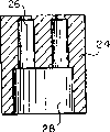
The second preformed plug 24 has been installed in last chamber 14.Shown in Fig. 7 and 9, plug 24 comprises the hole 26 of cavity 28 and support and alignment socket pin 36 and metal oxide varistor 30, and this remakes description in the back.Plug 20 and 24 all can be made of plastic.
With reference to figure 7, be metal oxide varistor 30 around each socket pins 36 again.Metal oxide varistor 30 is a tubulose, and compresses and be engaged on the socket pins.The length and the thickness of metal oxide varistor 30 have been determined actual breakdown voltage, thereby can adapt to special customer requirement.Can under about 1300 ℃ temperature, make metal oxide varistor by the compound of metal oxide powder being suppressed with the frangible ceramic body of sintering formation medium hardness.Should understand MOV of the present invention can produce with other suitable material and method that this specification sheets will be described.When assembling, metal oxide varistor 30 stretches in the cavity 28 and 18 of plug 24 and 20.
Following chamber 12 also comprises the low metal sleeve of ohmage 34, is used for providing between metal oxide varistor 30 and body skin 10 being electrically connected.The hole 32 that sleeve pipe 34 passes through socket pins 36 and each peripheral metal oxide varistor 30 when being included in the assembling detonator.Sleeve pipe 34 is clipped between plug 20 and 24, thereby each hole 26,32 and 22 in line.
Be contained on the body skin assembly is glass to metal seal head 40.Glass to metal seal provides the method that makes electric conductor pass through another environment airtightly from an environment.In addition, glass also is used as between the pin and the insulator between pin and the body skin except playing sealing function.By being fixed in, body skin and pin wherein make glass to metal seal assembly of the present invention in the graphite cake.Place glass mixture in required zone, then anchor clamps are placed on the belt conveyor that makes anchor clamps pass through high temperature furnace, this high temperature furnace makes it liquefy to the temperature build-up of glass.When high temperature furnace fell back on cooling room, glass solidification also adhered to the metal surface, formed the hermetic seal between pin and glass and body skin and the glass.
For hermetic seal is provided, glass to metal seal head 40 by Fig. 7 38 shown in circumference laser welding or adhering method be installed on the body skin 10.Laser welding/technique for sticking can provide good circumference hermetic seal.
As shown in Figure 7, being installed on the glass to metal seal head 40 is skid bed 48 and the cover plate dish assembly 44 that comprises pyrotechnic material.For extra hermetic seal is provided, use circumference laser welding/adhering method 38 that skid bed 48 is installed to head 40, disc 44 is installed to skid bed 48.
Figure 10 has disclosed second embodiment of high pressure resistant initiator of the present invention.The embodiment of Figure 10 is except being undertaken solid supplies with by being encapsulated in pins 50 in the glass to metal seal spare 40, and is identical with previous embodiment.If possible, identical label is used to represent identical part among all embodiment of the present invention.Because pin 50 does not comprise the socket described in first embodiment, the hole 26 of plug 24 can be a little bit smaller a little.
Then, will the method for the high pressure resistant initiator of assembly drawing 7 be described.Plug 20 and sleeve pipe 34 are pressed together in the following chamber 12 of body skin 10.Then, metal oxide varistor 30 compresses and is engaged in around each contact pin 36.Then the sub-component of contact pin 36 and metal oxide varistor 30 formations is inserted in the cavity 26 and 28 of plug 24.Then this sub-component is inserted in the cavity 14 of body skin 10, stretch in the hole 22 of plug 20 up to the solid-end that contacts pin 36.
The pin 42 that integrated circuit 46 is housed in the glass to metal seal head 40 inserts in the socket of pin 36, and skid bed 48 places on the head 40.Utilization circumference welding/adhering method 38 is installed to head on the body skin 10, and skid bed 48 is installed on the head 40.Then pyrotechnics mixture of powders 54 skid bed 48 of packing into, and with circumference welding/adhering method 38 cover plate dish 44 is installed on the skid bed 38.Method with any appropriate is installed in body skin 10 on the inflation pump then.
During the high pressure resistant initiator of assembling Figure 10, plug 20 and sleeve pipe 34 pressings are gone in the following chamber 12 of body skin 10.Then, plug 20 and sleeve pipe 35 pressings are gone in the following chamber 12 of body skin 10.Then the glass to metal seal head assembly that is made of head 40 and pin 50 is inserted in the cavity 26 of plug 24, metal oxide varistor 30 compress be engaged in every contact pin 50 around and insert in the cavity 28 of plug 24.Then this sub-component is inserted in the cavity 14 of body skin 10, stretch in the hole 22 of plug 20 up to the solid-end of pin 50.
Skid bed 48 places on the head 40, and utilization circumference welding/adhering method 38 is installed to head on the body skin 10, and skid bed 48 is installed on the head 40.Then pyrotechnics mixture of powders 54 skid bed 48 of packing into, and with circumference welding/adhering method 38 cover plate dish 44 is installed on it.Method with any appropriate is installed to body skin 10 in the inflation pump then.
With reference to Figure 11 and 12, will the 3rd embodiment of high pressure resistant initiator of the present invention be described.Body skin 10 comprises the plastic plug 56 that is pressed together on down the single preformed in the chamber 12.Plug 56 is cup-shaped, has and the close-fitting interface feature of security system electric wiring assembly (not shown) along its inside face.
The last chamber 14 of body skin 10 comprises metal oxide varistor 30 and glass to metal seal head 40.Metal oxide varistor 30 can be a) to carry out sintering operation formation subsequently by solidifying the metal oxide powder composition that forms again around each pin 50; Or b) metal oxide powder and glass mixture are mixed with after the integrated bond cmpd of the glass to metal seal head that sintering operation forms, so formed the metal oxide varistor and the glass to metal seal of integrated bond; Or c) prefabricated dummy slider or inserted sheet carry out sintering to be formed on the firm stupalith that is pressed into the position in the manufacturing process by the formation of curing metal oxide powder and to this dummy slider.
In another changed, metal oxide varistor can be positioned on the IC chip case chip of chamber 14, or integrated circuit 46 and rheostat can be positioned on the single integrated circuit sheet.
In the embodiment of Figure 11 and 12, glass to metal seal head 40 comprises the passage 60 as the aligning guide of integrated circuit 46 between the pin 50.With reference to figure 6, on integrated circuit bridge circuit element directly deposit as the explosive compound 62 of principal point burning things which may cause a fire disaster.
Be installed on the body skin 10 is skid bed 48 and cover plate dish 44 assemblies that comprise firework mixture 54.For hermetic seal is provided, by circumference laser welding/adhering method 38 skid bed 48 is installed on the body skin 10, and dish 44 is installed on the frame 48.
The embodiment of Figure 13 is except substituting the skid bed 48 and shrouding disc 44 assemblies of previous embodiment with tea cup with a cover 68, the embodiment of same Figure 11-12 is the same.Tea cup with a cover 68 is single parts, it be one comprise firework mixture 54 and be hermetically sealed to the sealing of body skin 10 by circumference laser welding/adhering method 38 at the bottom of cup.
The embodiment of Figure 14 is except body skin 10 comprises the end wall 8 of elongation, and the embodiment of same Figure 11-12 is the same, and therefore end wall 8 does not need independently skid bed 48 as the skid bed of firework mixture.So glass to metal seal head 40 can be hidden in the body skin 10.The cup-shaped cover plate dish that is similar to Figure 11 mid-game 44 is installed on the sidewall 8 of body skin 10 by circumference laser welding/adhering method 38.
Then, will the assemble method of Figure 11-14 embodiment be described.Metal oxide varistor can form with glass to metal seal, to make the integrated bond assembly that comprises body skin 10, pin 50, head 40 and metal oxide varistor 30.Metal oxide varistor also can be the independent component that inserts in the head of glass 40 dead aft cavitys.Plug 56 is press-fitted in the body skin 10, arrives cavity bottom up to it.Between pin 50 along passage 60 deposits binding, so that integrated circuit 46 is fixed on the head of glass 40.As autoregistration mechanism integrated circuit 46 is positioned between the pin 50 then.Can use electroconductive binder, wire bonds or scolder that integrated circuit 46 and pin 50 are electrically connected.
With reference to the embodiment of Figure 11, then skid bed 48 is installed on the body skin 10, and the firework mixture 54 of in skid bed 48, packing into.By circumference laser welding/adhering method 38 cover plate dish 44 is installed on the skid bed 48 then.
Then, with reference to Figure 12, detonation layer 62 is directly placed on the integrated circuit bridge circuit element, and make its drying.Remaining number of assembling steps is similar to Figure 11,13 and 14 embodiment.Should understand detonation layer 62 and can be used for all embodiment of the present invention.
According to the embodiment of Figure 13, cup 68 is equipped with firework mixture and is installed on the body skin 10 by circumference welding/adhering method 38.In the embodiment of Figure 14, firework mixture 54 is loaded in the cavity, and cover plate dish 44 is installed to body skin 10 by circumference welding/adhering method 38.
Though described the present invention corresponding to specific embodiments, many other variation and change and other application will become obviously to those those of skill in the art in this area.Therefore, preferably only limit the present invention with additional claim, rather than the special here content that discloses.
Claims (23)
1. the high pressure resistant initiator of car occupant security personnel electric system is characterized in that comprising:
Body skin with last chamber and following chamber;
The glass to metal seal head that on body skin, forms, the glass to metal seal head comprises the IC apparatus that is used to light pyrotechnic material;
Be used for this IC apparatus is linked the connecting device of auto electric joint, wherein descend the chamber that this electrical connector can be installed;
Place the electrostatic discharge protective device of this body skin, be used for this connecting device is carried out electrostatic discharge protective;
Be contained in the device that is used to hold pyrotechnic material on the body skin; And
Be used for the glass to metal seal head is hermetically sealed to the device of body skin.
2. high pressure resistant initiator as claimed in claim 1 is characterized in that electrostatic discharge protective device comprises metal oxide varistor.
3. high pressure resistant initiator as claimed in claim 2 is characterized in that metal oxide varistor comprises having the integrated bond thing that carries out the glass to metal seal head that forms behind the sintering operation subsequently by metal oxide powder is mixed with glass mixture.
4. high pressure resistant initiator as claimed in claim 2 is characterized in that connecting device comprises a pair of elongation pin of chamber and following chamber on the break-through body skin.
5. high pressure resistant initiator as claimed in claim 4 is characterized in that the metal oxide powder composition that reconstitutes by curing carries out sintering operation subsequently and forms metal oxide varistor around every pin.
6. high pressure resistant initiator as claimed in claim 4, it is characterized in that described metal oxide varistor comprises prefabricated inserted sheet, it forms by the curing metal oxide powder, and inserted sheet is carried out sintering go into the firm stupalith of body skin, this inserted sheet of pair of pins break-through to form pressing.
7. high pressure resistant initiator as claimed in claim 6 is characterized in that metal oxide varistor is that tubulose and compressing is engaged on the every pin.
8. high pressure resistant initiator as claimed in claim 4 is characterized in that the preformed plug that comprises that also at least one places chamber under the body skin, and this preformed plug comprises the device that joins with electrical connector.
9. high pressure resistant initiator as claimed in claim 4, it is characterized in that on body skin, being provided with in the chamber the first preformed plug, be provided with the second preformed plug in the following chamber of body skin, first and second plugs all comprise the device that is used to hold metal oxide varistor and pin.
10. high pressure resistant initiator as claimed in claim 9 is characterized in that also comprising the low metal sleeve of ohmage that places between body skin first and second plugs, is used for providing between metal oxide varistor and body skin being electrically connected.
11. high pressure resistant initiator as claimed in claim 4 is characterized in that the glass to metal seal head comprises and this head pin that pin is cooperated.
12. high pressure resistant initiator as claimed in claim 11, the diameter that it is characterized in that each head pin are about 0.508 millimeter.
13. high pressure resistant initiator as claimed in claim 1, the device that it is characterized in that being used to loading pyrotechnic material comprises skid bed and the cover plate dish assembly that installs to body skin, and the sealing of glass to metal seal head gas is connected in the skid bed.
14. high pressure resistant initiator as claimed in claim 1, the device that it is characterized in that being used to loading pyrotechnic material comprises the tea cup with a cover with the body skin hermetic seal.
15. high pressure resistant initiator as claimed in claim 1 is characterized in that body skin comprises the end wall of elongation, this end wall and cover plate dish comprise the device that loads pyrotechnic material, and the cover plate dish is hermetically sealed on the end wall.
16. high pressure resistant initiator as claimed in claim 4 is characterized in that the glass to metal seal head comprises along the passage of the diameter elongation of glass to metal seal head, is used to aim at the IC apparatus between the pin of this passage of break-through.
17. high pressure resistant initiator as claimed in claim 16 is characterized in that IC apparatus comprises the printed circuit board (PCB) between the pin that is located at the elongation of passage lastblock, is provided with the explosive mixture layer on printed circuit board (PCB).
18. high pressure resistant initiator as claimed in claim 1 is characterized in that airtight connection comprises the circumference laser welding.
19. high pressure resistant initiator as claimed in claim 1, it is bonding to it is characterized in that airtight connection comprises.
20. a method of assembling high pressure resistant initiator, this high pressure resistant initiator comprise the single-piece electrostatic discharge protective of car occupant security personnel electric system, it is characterized in that the method may further comprise the steps:
Provide the body skin of chamber and following chamber;
The device that is used to make detonator to link the auto electric joint is inserted upper and lower chamber;
Be formed for detonator is carried out the electrostatic discharge protective device of electrostatic discharge protective;
Electrostatic discharge protective device is inserted in the body skin, and electrostatic discharge protective device links to each other with connecting device;
Enclosure interior forms the glass to metal seal head outside, and the glass to metal seal head comprises the IC apparatus of lighting pyrotechnic material; And
Body skin is received in the device sealing that is used to load pyrotechnic material.
21. method as claimed in claim 20, it is characterized in that connecting device comprises the break-through body skin a pair of elongation pin of chamber up and down, the step that forms metal oxide varistor comprises solidifies the metal oxide powder composition that reconstitutes around each pin, and the metal oxide powder that reconstitutes of sintering.
22. method as claimed in claim 20, it is characterized in that the step that forms metal oxide varistor comprises that a metal oxide powder composition that reconstitutes is cured in the prefabricated inserted sheet, and inserted sheet carried out sintering, go into the firm stupalith of body skin to be formed on pin top pressing.
23. method as claimed in claim 20, it is characterized in that connecting device comprises the break-through body skin a pair of elongation pin of chamber up and down, the step that forms the glass to metal seal head comprises body skin and pin is fixed on the graphite cake, glass mixture is inserted in the body skin, graphite cake is heated to makes glass mixture be elevated to liquid high temperature, the glass mixture that cooling is liquid, solidify and adhere on body skin and the pin up to glass, to form hermetic seal between pin and the glass that solidifies and between body skin and the glass that solidifies.
Applications Claiming Priority (3)
| Application Number | Priority Date | Filing Date | Title |
|---|---|---|---|
| US08/632,700 US5932832A (en) | 1996-04-15 | 1996-04-15 | High pressure resistant initiator with integral metal oxide varistor for electro-static discharge protection |
| US08/632700 | 1996-04-15 | ||
| US08/632,700 | 1996-04-15 |
Publications (2)
| Publication Number | Publication Date |
|---|---|
| CN1168466A CN1168466A (en) | 1997-12-24 |
| CN1097532C true CN1097532C (en) | 2003-01-01 |
Family
ID=24536567
Family Applications (1)
| Application Number | Title | Priority Date | Filing Date |
|---|---|---|---|
| CN97110118A Expired - Fee Related CN1097532C (en) | 1996-04-15 | 1997-04-15 | High pressure resistant initiator with integral metal oxide varistor for electro-static discharge protection |
Country Status (11)
| Country | Link |
|---|---|
| US (1) | US5932832A (en) |
| EP (1) | EP0802092A1 (en) |
| JP (2) | JPH1035400A (en) |
| KR (1) | KR100260978B1 (en) |
| CN (1) | CN1097532C (en) |
| AR (1) | AR006642A1 (en) |
| AU (1) | AU700900B2 (en) |
| BR (1) | BR9701787A (en) |
| CA (1) | CA2201699A1 (en) |
| PL (1) | PL319476A1 (en) |
| ZA (1) | ZA972948B (en) |
Cited By (1)
| Publication number | Priority date | Publication date | Assignee | Title |
|---|---|---|---|---|
| CN104080660A (en) * | 2011-04-08 | 2014-10-01 | 奥托里夫Asp股份有限公司 | Initiator with molded ESD dissipater |
Families Citing this family (74)
| Publication number | Priority date | Publication date | Assignee | Title |
|---|---|---|---|---|
| US6070531A (en) * | 1997-07-22 | 2000-06-06 | Autoliv Asp, Inc. | Application specific integrated circuit package and initiator employing same |
| DE19733353C1 (en) * | 1997-08-01 | 1998-12-10 | Nico Pyrotechnik | Ignition unit for a personal protection device in a motor vehicle |
| US6250952B1 (en) | 1997-08-08 | 2001-06-26 | The Whitaker Corporation | Air bag connector |
| DE19801772C1 (en) * | 1998-01-19 | 1999-04-22 | Autoliv Dev | Igniter for gas generator of motor vehicle airbag |
| DE29807096U1 (en) * | 1998-04-20 | 1998-08-20 | TRW Occupant Restraint Systems GmbH & Co. KG, 73553 Alfdorf | Device containing pyrotechnic material |
| DE29810006U1 (en) | 1998-06-04 | 1998-10-01 | TRW Occupant Restraint Systems GmbH & Co. KG, 73553 Alfdorf | Igniter for a gas generator |
| DE19836280C1 (en) * | 1998-08-11 | 2000-05-11 | Telefunken Microelectron | Pyrotechnic igniter with integrated electronics to trigger a restraint system |
| FR2784176B1 (en) * | 1998-10-06 | 2004-11-26 | Livbag Snc | ELECTRO-PYROTECHNIC INITIATION SYSTEM PROTECTED AGAINST ELECTROSTATIC DISCHARGES |
| US6249228B1 (en) * | 1998-10-23 | 2001-06-19 | Trw Inc. | Vehicle occupant protection device and system having an anti-theft, anti-tamper feature |
| DE19856325A1 (en) | 1998-12-07 | 2000-06-15 | Bosch Gmbh Robert | Ignition device for restraint devices in a vehicle |
| FR2790078B1 (en) | 1999-02-18 | 2004-11-26 | Livbag Snc | ELECTROPYROTECHNIC IGNITER WITH ENHANCED IGNITION SAFETY |
| GB2347485A (en) | 1999-03-05 | 2000-09-06 | Breed Automotive Tech | Pretensioner |
| US6157548A (en) * | 1999-03-25 | 2000-12-05 | Illinois Tool Works Inc. | Electrically shielded housing |
| JP2000292100A (en) * | 1999-04-09 | 2000-10-20 | Showa Kinzoku Kogyo Kk | Electric ignition type gas generator |
| WO2001001061A1 (en) * | 1999-06-25 | 2001-01-04 | Dynamit Nobel Gmbh Explosivstoff- Und Systemtechnik | Ignition unit with an integrated electronic system |
| JP4426079B2 (en) | 1999-09-27 | 2010-03-03 | ダイセル化学工業株式会社 | Initiator assembly |
| FR2800865B1 (en) * | 1999-11-05 | 2001-12-07 | Livbag Snc | PYROTECHNIC INITIATOR WITH PHOTOGRAVE FILAMENT PROTECTED AGAINST ELECTROSTATIC DISCHARGES |
| US6357355B1 (en) * | 2000-02-10 | 2002-03-19 | Trw Inc. | Pyrotechnic igniter with radio frequency filter |
| EP1139059B1 (en) * | 2000-03-28 | 2006-07-12 | Hirschmann Automotive GmbH | Ignition device for a safety system |
| FR2809806B1 (en) * | 2000-05-30 | 2003-01-10 | Livbag Snc | ELECTRO-PYROTECHNIC INITIATOR WITH A THIN FILM BRIDGE AND A VERY LOW OPERATING ENERGY |
| DE10027464A1 (en) * | 2000-06-02 | 2001-12-13 | Hirschmann Austria Gmbh Rankwe | Ignition device for a security system |
| JP4813642B2 (en) * | 2000-08-09 | 2011-11-09 | ダイセル化学工業株式会社 | Electric initiator and initiator assembly using the same |
| US6578487B2 (en) * | 2000-12-08 | 2003-06-17 | Special Devices, Inc. | Pyrotechnic initiator with a narrowed sleeve retaining a pyrotechnic charge and methods of making same |
| US7124688B2 (en) * | 2000-12-08 | 2006-10-24 | Special Devices, Inc. | Overmolded body for pyrotechnic initiator and method of molding same |
| WO2002088619A1 (en) * | 2001-04-27 | 2002-11-07 | Daicel Chemical Industries, Ltd. | Initiator assembly and gas generator using the same |
| US6467414B1 (en) * | 2001-06-29 | 2002-10-22 | Breed Automotive Technology, Inc. | Ignitor with printed electrostatic discharge spark gap |
| DE10133223A1 (en) * | 2001-07-09 | 2002-10-17 | Trw Airbag Sys Gmbh & Co Kg | Pyrotechnic igniter for air bag deployment has section of casing engaging recess to form catch connection |
| DE10133221A1 (en) * | 2001-07-09 | 2002-10-17 | Trw Airbag Sys Gmbh & Co Kg | Igniter for a gas generator has a charge case made of a readily combustible material to avoid filter blockage |
| US6622627B2 (en) * | 2001-12-13 | 2003-09-23 | Arie Sansolo | Actuator apparatus |
| EP1327850B1 (en) * | 2002-01-10 | 2006-05-17 | Davey Bickford | Electro-explosive initiator and method of manufacture |
| US6874423B2 (en) * | 2002-10-21 | 2005-04-05 | Schott Glas | Hermetically sealed electrical feed-through device with a straight isolated pin in an offset oval glass seal |
| US6907827B2 (en) * | 2002-11-14 | 2005-06-21 | Special Devices, Inc. | Pyrotechnic initiator having output can with encapsulation material retention feature |
| JP3803636B2 (en) | 2002-12-26 | 2006-08-02 | 本田技研工業株式会社 | Ignition device for bus connection |
| DE20314580U1 (en) * | 2003-03-03 | 2004-08-05 | Schott Glas | Metal-glass fastening equipment lead-through for airbag or seat belt tension triggers has metal pins in a through-opening and a main body with front and rear sides and a release action |
| US8327765B2 (en) * | 2003-03-03 | 2012-12-11 | Schott Ag | Metal fixing material bushing and method for producing a base plate of a metal fixing material bushing |
| DE10321935A1 (en) * | 2003-05-15 | 2004-12-02 | Trw Occupant Restraint Systems Gmbh & Co. Kg | Data storage system for a vehicle occupant restraint system |
| JP4094529B2 (en) * | 2003-11-10 | 2008-06-04 | 本田技研工業株式会社 | Ignition device |
| US20060208474A1 (en) * | 2003-12-24 | 2006-09-21 | Nippon Kayaku Kabushiki Kaisha | Gas producer |
| JP4335725B2 (en) | 2004-03-30 | 2009-09-30 | 日本化薬株式会社 | Gas generator |
| DE102004060734B4 (en) | 2004-12-15 | 2008-10-16 | Amphenol-Tuchel Electronics Gmbh | Contact protection for connectors with protective device against interference |
| DE102005004920B3 (en) | 2005-02-02 | 2006-08-17 | Amphenol-Tuchel Electronics Gmbh | Contact protection for connectors with a shorting bridge with integrated switching element |
| ATE453850T1 (en) * | 2005-04-04 | 2010-01-15 | Trw Airbag Sys Gmbh | MODULAR ELECTROPYROTECHNIC IGNITOR CONSISTING OF TWO HALF PARTS MADE OF PLASTIC |
| US20060260498A1 (en) * | 2005-04-05 | 2006-11-23 | Daicel Chemical Industries, Ltd. | Igniter assembly |
| US8733250B2 (en) | 2006-01-27 | 2014-05-27 | Schott Ag | Metal-sealing material-feedthrough and utilization of the metal-sealing material feedthrough with an airbag, a belt tensioning device, and an ignition device |
| EP2092161A4 (en) * | 2006-11-27 | 2012-01-18 | Halliburton Energy Serv Inc | Apparatus and methods for sidewall percussion coring using a voltage activated igniter |
| WO2008112235A1 (en) * | 2007-03-12 | 2008-09-18 | Dyno Nobel Inc. | Detonator ignition protection circuit |
| US20110002078A1 (en) * | 2007-06-09 | 2011-01-06 | Lansburg David F | Low-voltage-insensitive electro-pyrotechnic device |
| CN101772689A (en) * | 2007-06-13 | 2010-07-07 | 日本化药株式会社 | Squib, gas generation device for airbag, and gas generation device for seatbelt pretensioner |
| US7845277B2 (en) * | 2008-05-28 | 2010-12-07 | Autoliv Asp, Inc. | Header assembly |
| CN103465861A (en) | 2008-09-30 | 2013-12-25 | Trw空气气袋系统股份有限公司 | Gas generator, method for the production thereof and module having the gas generator |
| US8056477B2 (en) * | 2009-06-10 | 2011-11-15 | Autoliv Asp, Inc. | Protection system for use with airbag inflators and initiators |
| JP4644296B2 (en) * | 2009-07-29 | 2011-03-02 | 昭和金属工業株式会社 | Gas generator |
| DE102010045641A1 (en) | 2010-09-17 | 2012-03-22 | Schott Ag | Process for producing a ring-shaped or plate-shaped element |
| US10684102B2 (en) | 2010-09-17 | 2020-06-16 | Schott Ag | Method for producing a ring-shaped or plate-like element |
| DE102011107852A1 (en) * | 2011-07-01 | 2013-01-03 | Trw Airbag Systems Gmbh | Method for manufacturing igniter for ignition device of pyrotechnic gas generator of motor vehicle-passenger protection device, involves connecting resistance wire of lighter with connection element of lighter directly by wire bonding |
| DE102012004966B3 (en) * | 2012-03-14 | 2013-01-03 | A&O Technologie GmbH | Ignition base for pyroelectrically igniting propellant in pyroelectric igniter used in micro gas generator for e.g. airbag in motor car, has part of projecting pins, and base provided with plastic sheathing below front surface upto outlet |
| JP5897417B2 (en) * | 2012-07-13 | 2016-03-30 | 株式会社ダイセル | Cover member for igniter |
| US8720948B2 (en) | 2012-09-26 | 2014-05-13 | Ford Global Technologies, Llc | Active bolster with protected weld for bladder |
| US9248802B2 (en) * | 2012-11-29 | 2016-02-02 | Autoliv Asp, Inc. | Surface mount initiators |
| US9050944B1 (en) * | 2012-11-30 | 2015-06-09 | Tk Holdings Inc. | Gas generating system with initiator sub-assembly |
| US9157708B1 (en) * | 2013-05-07 | 2015-10-13 | The United States Of America As Represented By The Secretary Of The Army | Electric and magnetic field hardened igniter for electrically fired ammunition |
| US8936273B1 (en) | 2013-08-26 | 2015-01-20 | Ford Global Technologies, Llc | Weld seam stress relief for active bolster with plastic-molded bladder |
| KR102069626B1 (en) * | 2013-09-03 | 2020-01-23 | 삼성전기주식회사 | Printed Circuit Board |
| US9939235B2 (en) * | 2013-10-09 | 2018-04-10 | Battelle Energy Alliance, Llc | Initiation devices, initiation systems including initiation devices and related methods |
| US9061643B1 (en) | 2014-09-10 | 2015-06-23 | Ford Global Technologies, Llc | Active bolster with interlocking gas barrier |
| JP6721483B2 (en) * | 2016-10-07 | 2020-07-15 | 日本化薬株式会社 | Igniter |
| KR101778168B1 (en) * | 2017-04-13 | 2017-09-13 | 국방과학연구소 | Initiator for rocket motor |
| CN107514937B (en) * | 2017-09-22 | 2019-08-23 | 中国兵器工业第二一三研究所 | A kind of high pressure-bearing closure of segmentation sealing-in |
| CN110418493B (en) * | 2019-07-04 | 2022-04-05 | 榆林学院 | Piezoresistor electrostatic protection assembly |
| JP7286458B2 (en) * | 2019-07-22 | 2023-06-05 | 日本化薬株式会社 | igniter |
| FR3100666B1 (en) * | 2019-09-05 | 2022-09-02 | Aptiv Tech Ltd | Connection set for passive safety device, protected against electrostatic discharge |
| RU2728908C1 (en) * | 2019-09-10 | 2020-08-03 | Российская Федерация, от имени которой выступает Государственная корпорация по атомной энергии "Росатом" (Госкорпорация "Росатом") | Electric fuse |
| CN110887413A (en) * | 2019-11-27 | 2020-03-17 | 西安航天动力研究所 | High insensitive miniaturized electric detonator |
| RU2756030C1 (en) * | 2021-01-11 | 2021-09-24 | Российская Федерация, от имени которой выступает Государственная корпорация по атомной энергии "Росатом" (Госкорпорация "Росатом") | Induction detonator (options) |
Family Cites Families (40)
| Publication number | Priority date | Publication date | Assignee | Title |
|---|---|---|---|---|
| US2408124A (en) * | 1941-09-11 | 1946-09-24 | Rolfes Hans Jay | Means for safeguarding electric igniters of blasting detonators against accidental firing |
| GB927705A (en) * | 1960-09-20 | 1963-06-06 | Graviner Manufacturing Co | Improvements in or relating to explosive charges |
| US3318243A (en) * | 1963-10-03 | 1967-05-09 | Atlas Chem Ind | Static protected detonator |
| US3420174A (en) * | 1967-09-29 | 1969-01-07 | Us Navy | Pulse sensitive electro-explosive device |
| US3683811A (en) * | 1970-06-22 | 1972-08-15 | Hercules Inc | Electric initiators for high energy firing currents |
| US3821686A (en) * | 1971-10-21 | 1974-06-28 | Gen Electric | Protective connector devices |
| US3928245A (en) * | 1973-07-09 | 1975-12-23 | Gen Electric | Metal oxide voltage-variable resistor composition |
| US4041436A (en) * | 1975-10-24 | 1977-08-09 | Allen-Bradley Company | Cermet varistors |
| JPS5261212A (en) * | 1975-11-13 | 1977-05-20 | Toyota Motor Co Ltd | Electric detonator |
| US4103274A (en) * | 1976-09-13 | 1978-07-25 | General Electric Company | Reconstituted metal oxide varistor |
| US4103619A (en) * | 1976-11-08 | 1978-08-01 | Nasa | Electroexplosive device |
| US4306499A (en) * | 1978-04-03 | 1981-12-22 | Thiokol Corporation | Electric safety squib |
| US4422381A (en) * | 1979-11-20 | 1983-12-27 | Ici Americas Inc. | Igniter with static discharge element and ferrite sleeve |
| DE3111080A1 (en) * | 1981-03-20 | 1982-09-30 | Heinrich Kopp Gmbh & Co Kg, 8756 Kahl | OVERVOLTAGE PROTECTION DEVICE FOR ELECTRICAL HOME INSTALLATION SYSTEMS |
| US4441427A (en) * | 1982-03-01 | 1984-04-10 | Ici Americas Inc. | Liquid desensitized, electrically activated detonator assembly resistant to actuation by radio-frequency and electrostatic energies |
| US4517895A (en) * | 1982-11-15 | 1985-05-21 | E. I. Du Pont De Nemours And Company | Electric initiator resistant to actuation by radio frequency and electrostatic energies |
| SE442674B (en) * | 1984-05-14 | 1986-01-20 | Bofors Ab | DEVICE FOR BUILT-IN ELTENDDON |
| CH663089A5 (en) * | 1984-05-21 | 1987-11-13 | Inventa Ag | POLE BODY FOR AN ELECTRIC IGNITION DEVICE, METHOD FOR THE PRODUCTION THEREOF AND THE USE THEREOF. |
| US4901183A (en) * | 1988-08-29 | 1990-02-13 | World Products, Inc. | Surge protection device |
| US5243911A (en) * | 1990-09-18 | 1993-09-14 | Dow Robert L | Attenuator for protecting electronic equipment from undesired exposure to RF energy and/or lightning |
| US5355800A (en) * | 1990-02-13 | 1994-10-18 | Dow Robert L | Combined EED igniter means and means for protecting the EED from inadvertent extraneous electricity induced firing |
| US5036768A (en) * | 1990-02-13 | 1991-08-06 | Dow Robert L | Attenuator for dissipating electromagnetic and electrostatic energy |
| US5016914A (en) * | 1990-02-14 | 1991-05-21 | Trw Vehicle Safety Systems Inc. | Vehicle occupant restraint system |
| US5057041A (en) * | 1990-06-29 | 1991-10-15 | Foxconn International | User configurable integrated electrical connector assembly |
| US5131679A (en) * | 1990-12-18 | 1992-07-21 | Trw Inc. | Initiator assembly for air bag inflator |
| US5241910A (en) * | 1991-04-05 | 1993-09-07 | Morton International, Inc. | Universal squib connector for a gas generator |
| US5200574A (en) * | 1991-04-05 | 1993-04-06 | Morton International, Inc. | Universal squib connector |
| US5230287A (en) * | 1991-04-16 | 1993-07-27 | Thiokol Corporation | Low cost hermetically sealed squib |
| US5431101A (en) * | 1991-04-16 | 1995-07-11 | Thiokol Corporation | Low cost hermetically sealed squib |
| US5367956A (en) * | 1992-02-07 | 1994-11-29 | Fogle, Jr.; Homer W. | Hermetically-sealed electrically-absorptive low-pass radio frequency filters and electro-magnetically lossy ceramic materials for said filters |
| FR2693721B1 (en) * | 1992-07-20 | 1994-10-21 | Ncs Pyrotechnie Technologies | Priming charge with annular percussion and its manufacturing process. |
| US5243492A (en) * | 1992-08-27 | 1993-09-07 | Coors Ceramics Company | Process for fabricating a hermetic coaxial feedthrough |
| DE4307774A1 (en) * | 1993-03-12 | 1994-09-15 | Dynamit Nobel Ag | Ignition device |
| FR2704944B1 (en) * | 1993-05-05 | 1995-08-04 | Ncs Pyrotechnie Technologies | Electro-pyrotechnic initiator. |
| ZA946555B (en) * | 1993-05-28 | 1995-06-12 | Altech Ind Pty Ltd | An electric igniter |
| JP2700100B2 (en) * | 1993-05-28 | 1998-01-19 | 日本工機株式会社 | Igniter |
| ZA948566B (en) * | 1993-11-18 | 1995-05-18 | Ici America Inc | Airbag igniter and method of manufacture |
| US5621183A (en) * | 1995-01-12 | 1997-04-15 | Trw Inc. | Initiator for an air bag inflator |
| US5616881A (en) * | 1995-05-30 | 1997-04-01 | Morton International, Inc. | Inflator socket pin collar for integrated circuit initaitor with integral metal oxide varistor for electro-static discharge protections |
| US5558366A (en) * | 1995-08-22 | 1996-09-24 | Trw Inc. | Initiator assembly for air bag inflator |
-
1996
- 1996-04-15 US US08/632,700 patent/US5932832A/en not_active Expired - Fee Related
-
1997
- 1997-04-02 AU AU16661/97A patent/AU700900B2/en not_active Ceased
- 1997-04-03 CA CA002201699A patent/CA2201699A1/en not_active Abandoned
- 1997-04-07 ZA ZA9702948A patent/ZA972948B/en unknown
- 1997-04-14 BR BR9701787A patent/BR9701787A/en not_active Application Discontinuation
- 1997-04-14 KR KR1019970013565A patent/KR100260978B1/en not_active IP Right Cessation
- 1997-04-14 AR ARP970101490A patent/AR006642A1/en unknown
- 1997-04-14 PL PL97319476A patent/PL319476A1/en unknown
- 1997-04-14 JP JP9096162A patent/JPH1035400A/en active Pending
- 1997-04-15 CN CN97110118A patent/CN1097532C/en not_active Expired - Fee Related
- 1997-04-15 EP EP97302557A patent/EP0802092A1/en not_active Withdrawn
-
1998
- 1998-10-16 JP JP1998008167U patent/JP3058511U/en not_active Expired - Lifetime
Cited By (2)
| Publication number | Priority date | Publication date | Assignee | Title |
|---|---|---|---|---|
| CN104080660A (en) * | 2011-04-08 | 2014-10-01 | 奥托里夫Asp股份有限公司 | Initiator with molded ESD dissipater |
| CN104080660B (en) * | 2011-04-08 | 2016-08-17 | 奥托里夫Asp股份有限公司 | There is the trigger of the electrostatic discharge dissipative device of molding |
Also Published As
| Publication number | Publication date |
|---|---|
| KR100260978B1 (en) | 2000-08-01 |
| MX9702543A (en) | 1998-03-31 |
| PL319476A1 (en) | 1997-10-27 |
| AR006642A1 (en) | 1999-09-08 |
| AU1666197A (en) | 1997-10-23 |
| JPH1035400A (en) | 1998-02-10 |
| ZA972948B (en) | 1997-11-03 |
| EP0802092A1 (en) | 1997-10-22 |
| JP3058511U (en) | 1999-06-18 |
| KR970069648A (en) | 1997-11-07 |
| CN1168466A (en) | 1997-12-24 |
| AU700900B2 (en) | 1999-01-14 |
| BR9701787A (en) | 1998-11-10 |
| US5932832A (en) | 1999-08-03 |
| CA2201699A1 (en) | 1997-10-15 |
Similar Documents
| Publication | Publication Date | Title |
|---|---|---|
| CN1097532C (en) | High pressure resistant initiator with integral metal oxide varistor for electro-static discharge protection | |
| US5431101A (en) | Low cost hermetically sealed squib | |
| US5230287A (en) | Low cost hermetically sealed squib | |
| US5639986A (en) | Airbag igniter and method of manufacture | |
| US6408759B1 (en) | Initiator with loosely packed ignition charge and method of assembly | |
| EP0779492B1 (en) | Inflator initiator with zener diode electrostatic discharge protector | |
| US6009809A (en) | Bridgewire initiator | |
| CA2360362C (en) | Igniter | |
| US5433147A (en) | Ignition device | |
| US5728964A (en) | Electrical initiator | |
| US8196512B1 (en) | Plastic encapsulated energetic material initiation device | |
| US5596163A (en) | Gas generator igniting capsule | |
| CN1269007A (en) | Ignition unit for passenger protection device of motor vehicle | |
| US5616881A (en) | Inflator socket pin collar for integrated circuit initaitor with integral metal oxide varistor for electro-static discharge protections | |
| CN1245558A (en) | Hybrid electronic detonator delay circuit assembly | |
| EP1738972A1 (en) | "Single stage airbag infaltor" | |
| KR101083526B1 (en) | Single increment initiator charges | |
| CN104567555A (en) | Igniting unit for an inflator, inflator, airbag module, vehicle safety system and method of manufacturing an igniting unit | |
| CA1144817A (en) | Electric igniter including two conductive bodies separated by an insulating body, a connective member and a pyrotechnic charge | |
| JPS6233515B2 (en) | ||
| GB2315118A (en) | Electro-explosvie device | |
| CN2580395Y (en) | Conductive film electric detonator without bridge-wire | |
| MXPA97002543A (en) | High pressure resistant initiator, integrated with metallic oxide varistor for protection against download electrostat |
Legal Events
| Date | Code | Title | Description |
|---|---|---|---|
| C10 | Entry into substantive examination | ||
| SE01 | Entry into force of request for substantive examination | ||
| C06 | Publication | ||
| PB01 | Publication | ||
| C14 | Grant of patent or utility model | ||
| GR01 | Patent grant | ||
| C19 | Lapse of patent right due to non-payment of the annual fee | ||
| CF01 | Termination of patent right due to non-payment of annual fee |