CN109700378B - Surface cleaning head for a vacuum cleaner - Google Patents
Surface cleaning head for a vacuum cleaner Download PDFInfo
- Publication number
- CN109700378B CN109700378B CN201910102865.1A CN201910102865A CN109700378B CN 109700378 B CN109700378 B CN 109700378B CN 201910102865 A CN201910102865 A CN 201910102865A CN 109700378 B CN109700378 B CN 109700378B
- Authority
- CN
- China
- Prior art keywords
- liquid
- dirty liquid
- dirty
- liquid recovery
- air escape
- Prior art date
- Legal status (The legal status is an assumption and is not a legal conclusion. Google has not performed a legal analysis and makes no representation as to the accuracy of the status listed.)
- Active
Links
Images

Abstract
The invention relates to a surface cleaning head for a vacuum cleaner, comprising a head part provided with a suction port and a liquid spray nozzle, and an upright part, wherein the upright part is provided with a liquid supply tank and a dirty liquid recovery system; the dirty liquid recovery system comprises a gas-liquid separator, a dirty liquid input passage communicating a suction port with the gas-liquid separator, a dirty liquid recovery box with a dirty liquid recovery chamber inside, and an air escape passage for escaping air after separation, wherein a floater moving up and down along with the liquid level in the dirty liquid recovery chamber is arranged in the dirty liquid recovery chamber, and a movable blocking piece is arranged in the air escape passage; when the blocking piece is positioned at a set position, the air escape passage is blocked by the blocking piece; the first magnetic attraction piece and the second magnetic attraction piece are arranged on the floater and the blocking piece respectively and are matched with each other in a magnetic attraction mode to fix the floater and the blocking piece, so that the floater and the blocking piece form a linkage relation. According to the scheme, the floater and the blocking piece which are in linkage relation are arranged, so that dirty liquid can be effectively prevented from entering the air escape passage after the dirty liquid recovery box is full of liquid.
Description
Technical Field
The present invention relates to the field of vacuum cleaners, and in particular to a surface cleaning head for attachment to a vacuum cleaner for wet cleaning of a surface.
Background
In the prior art, for wet cleaning of a surface to be cleaned, specialized wet cleaning devices have been provided which include a cleaning liquid delivery system for delivering a cleaning liquid to the surface to be cleaned, and a dirt recovery system for extracting spent cleaning fluid and debris (which may include dirt, dust, stains, dirt, hair, and other debris) from the surface. The cleaning liquid delivery system generally includes a supply tank for storing cleaning liquid, a spray nozzle for applying the cleaning liquid to the surface to be cleaned, and a fluid supply conduit for delivering the cleaning liquid from the supply tank to the spray nozzle. An agitator may be provided for agitating the cleaning fluid on the surface. A dirty liquid recovery system typically includes a dirty liquid recovery tank, a suction opening facing a surface to be cleaned and in fluid communication with the dirty liquid recovery tank through a working air conduit, and a suction source in fluid communication with the working air conduit to draw cleaning fluid from the surface to be cleaned and discharge the cleaning fluid through the suction opening and the working air conduit to the dirty liquid recovery tank.
Among the above-described wet cleaning apparatuses, a typical apparatus is disclosed in chinese patent publication No. CN206434268U, which discloses a surface cleaning apparatus comprising: a housing comprising an upright handle assembly and a base mounted to the upright handle assembly and adapted to move over a surface to be cleaned. The surface cleaning apparatus is further provided with a fluid delivery system comprising: a fluid dispenser; and at least one fluid delivery channel forming a portion of the fluid delivery path. The fluid delivery channel may be formed by a portion of the suction nozzle assembly on the base.
As a common household cleaning device, a vacuum cleaner is used for adsorbing dust and garbage on a dry floor, and the vacuum cleaner cannot work on a wet floor with dirty liquid or a floor which needs to be cleaned while spraying water. The reasons for its inoperability are mainly: the dirty liquid is easily sucked into the vacuum cleaner, but the suction motor assembly in the vacuum cleaner is usually not waterproof, and the water vapor entering into the motor assembly can damage the motor and cause the motor not to work normally.
A prior chinese patent application publication No. CN108478097A discloses a vacuum cleaner capable of attaching a cleaning attachment to perform a wet cleaning operation, and a chinese published patent document No. CN104768439A also discloses a moisture absorbing attachment attached to a dry vacuum cleaner for cleaning purposes. The attachments in both of the above documents achieve an expansion of the range of use of the vacuum cleaner using the ordinary dry vacuum motor, but both of them have disadvantages in terms of suction force and reliability of gas-liquid separation.
Disclosure of Invention
In view of the above, it is an object of the present invention to provide a surface cleaning head that achieves reliable gas-liquid separation at high suction.
In order to achieve the purpose of the invention, the invention adopts the following technical scheme: a surface cleaning head for a vacuum cleaner, comprising:
a head adapted to be moved over a surface to be cleaned, said head having a suction opening for drawing dirty liquid together with air into said head and at least one spray nozzle for delivering cleaning liquid;
the lower part of the upright part is rotationally connected with the head, and a liquid supply tank for containing cleaning liquid and a dirty liquid recovery system which is in fluid communication with the suction port are arranged on the upright part;
the dirty liquid recovery system comprises a gas-liquid separator for separating dirty liquid from air, a dirty liquid input passage for communicating the suction port with the gas-liquid separator, a detachable dirty liquid recovery box and an air escape passage for escaping air after separation, wherein a dirty liquid recovery chamber is arranged in the dirty liquid recovery box, a floater which moves up and down along with the liquid level in the dirty liquid recovery chamber is arranged in the dirty liquid recovery chamber, and a movable blocking piece is arranged in the air escape passage; when the blocking piece is positioned at a set position, the air escape passage is blocked by the blocking piece; the first magnetic part is suitable for being matched with the second magnetic part in a magnetic attraction manner to fix the floater and the blocking part, so that the floater and the blocking part form a linkage relation; when the floater floats upwards to a set liquid level along with the liquid level in the dirty liquid recovery chamber, the blocking piece moves to the set position along with the floater to block the air escape passage.
In the above technical solution, preferably, the dirty liquid recovery tank includes a tank body and a detachable tank cover located at the top of the tank body, the tank cover is provided with a dirty liquid inlet and a guide member at least partially extending into the dirty liquid recovery chamber, the guide member extends in an up-and-down direction, and the float is mounted on the guide member and is limited to move only along the guide member.
In the above technical solution, preferably, the gas-liquid separator includes an upper housing, a water-vapor separating member detachably mounted in the upper housing, and a top cover disposed on the top of the upper housing and capable of being manually opened, and the blocking member is connected to the water-vapor separating member; when the top cover is opened, the moisture separator and the barrier can be taken out of the upper shell. Further preferably, the upper casing is located above the liquid supply tank and the dirty liquid recovery tank. Or further preferably, said moisture separator includes a filter in the path of said air escape path, said filter being disposed adjacent said top cover, said filter being exposed and separately removable when said top cover is opened.
In the above technical solution, preferably, the air escape passage includes an air escape chamber located directly above the contaminated fluid recovery chamber, and the blocking member is limited to be movable only in the air escape chamber. Further preferably, the bottom of the gas-liquid separator has an opening, the dirty liquid recovery chamber is located below the opening, the air escape chamber is located above the opening, and the air escape chamber has an air inlet and an air outlet; when the float floats upwards to a set liquid level, the blocking piece moves to the air outlet and blocks the air outlet, and the air escape passage is blocked.
In the above technical solution, preferably, the waste liquid input path includes a flexible hose as a hard waste liquid pipe located above the flexible hose, and an upper end portion of the hard waste liquid pipe extends into the gas-liquid separator. More preferably, the liquid supply tank and the dirty liquid recovery tank are respectively positioned at two opposite sides of the hard dirty liquid pipe.
The invention obtains the following beneficial technical effects: through set up the float in dirty liquid collection box and set up the separation piece that can link with the float in the air escape channel, its structure can effectively prevent dirty liquid collection box full liquid back dirty liquid and enter into the air escape route to because separation piece and float adopt magnetic element fixed mutually, the connected mode is simple, and it is more convenient to assemble.
Drawings
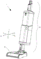
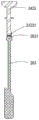
FIG. 1 is a perspective view of a surface cleaning head for a vacuum cleaner in accordance with the present invention;
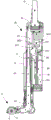
FIG. 2 is a schematic longitudinal cross-sectional view of a surface cleaning head of the present invention;
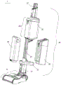
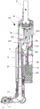
FIG. 3 is a disassembled schematic view of the surface cleaning head of the present invention;
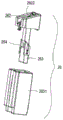
FIG. 4 is a disassembled view of the waste liquid recovery tank of the present invention;
FIG. 5 is a disassembled schematic view of the gas-liquid separator of the present invention;
FIG. 6 is a schematic view of the connection of the float and the barrier of the present invention;
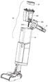
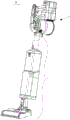
FIG. 7 is a perspective view of a vacuum cleaner incorporating a handheld vacuum cleaner of the present invention;
FIG. 8 is a schematic view of the direction of dirt liquid and air flow within the wet surface cleaning head of the present invention during operation of the vacuum cleaner;
FIG. 9 is a schematic view showing the positions of the components when the dirty liquid level in the dirty liquid recovery tank reaches a predetermined level during operation of the vacuum cleaner of the present invention;
wherein: 100. a vacuum cleaner; 1. a surface cleaning head; 2. a main machine of the dust collector; 10. a head portion; 20. an upright portion; 111. an upper cover; 112. a lower cover; 11. a housing; 113. a cover base; 12. a rolling brush chamber; 13. rolling and brushing; 14. a suction port; 15. a gap; 21. a lower connector; 22. a lower support table; 23. a sewage pipe; 24. an upper housing; 25. a liquid supply tank; 26. a dirty liquid recovery tank; 27. a connecting pipe; 251. a liquid supply chamber; 261. a dirty liquid recovery chamber; 262. a dirty liquid inlet; 263. a float; 241. gas-liquid inlet chamber; 242. an air escape chamber; 231. a flexible hose; 2411. an opening; 2421. an air inlet; 2422. an air outlet; 2423. a barrier; 28. a filter; 201. a gas-liquid separator; 202. a water-vapor separation member; 2601. a box body; 2602. a box cover; 264. a guide member; 2631. a magnetic member; 24231. a magnetic member; 203. and a top cover.
Detailed Description
For a detailed description of the technical contents, the structural features, the achieved objects and the effects of the invention, reference will be made to the embodiments illustrated in the accompanying drawings.
For purposes of description with respect to the figures, the terms "upper", "lower", "right", "left", "rear", "front", "vertical", "horizontal", "inner", "outer", and derivatives thereof shall relate to the perspective of a user from behind the cleaning base 1 (as oriented as shown in fig. 1).
Fig. 1 is a perspective view of a surface cleaning head 1 for a vacuum cleaner, the surface cleaning head 1 comprising a head 10 adapted to be moved over a surface to be cleaned and an upright 20 pivotally connected to the head 10 at a lower portion, the upright 20 being pivotable relative to the head 10 between an inclined position and an upright position.
As shown in FIG. 2, head 10 includes a housing 11 formed by an upper cover 111 and a lower cover 112, upper cover 111 and lower cover 112 being engaged and defining a partially enclosed chamber therebetween for accommodating a portion of the cleaning liquid delivery path and for accommodating a portion of the dirty liquid recovery path. The housing 11 further includes a cover base 113, the cover base 113 being coupled with a lower forward portion of the lower cover 112 to define a portion of the roll brush chamber 12, the roll brush chamber 12 having the roll brushes 13 mounted therein, and the roll brush chamber 12 having liquid injection nozzles (not shown) mounted therein for injecting the cleaning liquid into the roll brushes 13. A suction port 14 is arranged at the bottom of the lower cover 112, part of bristles of the rolling brush 13 extend to the outside through the suction port 14, and a gap 15 is formed between the rolling brush 13 and the inner wall surface of the upper cover 111 which is positioned at the front side of the rolling brush; when the rolling brush 13 rotates on the surface to be cleaned, the brush hairs on the rolling brush 13 pick up the dirty liquid and the solid waste on the surface to be cleaned by friction with the surface to be cleaned and send into the dirty liquid recovery pipe inside through the gap 15 together with air.
In this example, a cleaning liquid discharge system and a dirty liquid recovery system are provided in the surface cleaning head 1, and the cleaning liquid discharge system specifically includes a liquid supply tank 25, a liquid discharge nozzle, a cleaning liquid discharge path from the liquid supply tank 25 to the liquid discharge nozzle, and electronic components such as a necessary pump or valve unit provided in the cleaning liquid discharge path to control the discharge of the cleaning liquid.
The dirty liquid recovery system includes a gas-liquid separator 201 for separating dirty liquid from air, a dirty liquid input passage for communicating the suction port 14 and the gas-liquid separator 201, a dirty liquid recovery tank 26 for storing the separated dirty liquid, and an air escape passage for escaping the separated air.
As shown in the exploded view of the surface cleaning head 1 in fig. 3, the upright part 20 includes a lower connection head 21, a lower support table 22, a hard dirt tube 23 located in the middle, and an upper housing 24, and a liquid supply tank 25 and a dirt recovery tank 26 are separately detachable and installable between the lower connection head 21 and the lower support table 22. The upper casing 24 is a housing of the gas-liquid separator 201, the upper casing 24 is located above the liquid supply tank 25 and the dirty liquid recovery tank 26, an exhaust pipe 27 for connecting with a vacuum cleaner is provided on the top of the upper casing 24, and the exhaust pipe 27 constitutes a part of an air escape path. The hard soil liquid pipe 23 constitutes a part of the soil liquid input path. The liquid supply tank 25 and the foul liquid recovery tank 26 are located on opposite sides of the hard foul liquid pipe 23, respectively.
As further shown in fig. 2, the liquid supply tank 25 has a liquid supply chamber 251 therein for storing a cleaning liquid. The dirty liquid recovery tank 26 is provided therein with a dirty liquid recovery chamber 261 for storing dirty liquid. The dirt liquid input passage includes a section of flexible hose 231 located below the rigid dirt liquid pipe 23 in addition to the rigid dirt liquid pipe 23, and the flexible hose 231 passes through the lower connector 21 and communicates with the suction port 14 after passing through the junction between the upright part 20 and the head part 10. The suction port 14, the flexible hose 231, and the dirty liquid pipe 23 are connected in series to form a dirty liquid inlet passage for connecting the gas-liquid inlet chamber 241 and the suction port 14.
As shown in fig. 4, the dirty liquid recovery tank 26 includes a tank 2601 and a detachable tank cover 2602 positioned on the top of the tank 2601, the top of the tank cover 2602 is provided with a dirty liquid inlet 262 through which dirty liquid enters the tank, the tank cover 2602 is provided with a guide 264 extending downward into the dirty liquid recovery chamber 261, the guide 264 extends in the vertical direction, a float 263 that can move up and down is attached to the guide 264, and the float 263 is attached to the guide 264 and is limited to move up and down only along the guide 264.
Continuing with FIG. 2, the position of the float 263 inside the dirty liquid recovery chamber 261 is dependent on the liquid level of the dirty liquid recovery chamber 261. The upper housing 24 is provided therein with a gas-liquid inlet chamber 241 and an air escape chamber 242, the gas-liquid inlet chamber 241 is located above the dirty liquid recovery chamber 261, the gas-liquid inlet chamber 241 and the air escape chamber 242 are arranged side by side in the front-rear direction, and the upper portion of the dirty liquid pipe 23 extends upward into the gas-liquid inlet chamber 241. The bottom of the gas-liquid inlet chamber 241 is provided with an opening 2411, the upper end part of the sewage pipe 23 extending into the gas-liquid inlet chamber 242 is positioned above the opening 2411, and the sewage and air entering the gas-liquid inlet chamber 241 flow out of the gas-liquid inlet chamber 241 through the opening 2411. The air escape chamber 242 is for the outflow of air escaping from the opening 2411, and forms a part of an air escape passage, the air escape chamber 242 is located right above the dirty liquid recovery chamber 261, the air escape chamber 242 is provided with an air inlet 2421 and an air outlet 2422 located above the air inlet 2421, and the air inlet 2421 is located right above the dirty liquid inlet 262. Opening 2411 is located above the dirty liquid inlet 262 and below air inlet 2421 and is in communication with each other such that opening 2411 will be in communication with both the dirty liquid recovery chamber 261 and the air escape chamber 242 via dirty liquid inlet 262 and air inlet 2421. Air escape chamber 242 is provided with a barrier 2423 therein, barrier 2423 is limited to move only within air escape chamber 242, and air outlet 2422 is blocked when barrier 2423 is located at air outlet 2422. A barrier 2423 is provided in conjunction with float 263, the position of barrier 2423 inside air escape chamber 242 being dependent on the position of float 263; when float 263 floats upward to a set level (e.g., a set upper level limit), obstructor 2423 also moves upward to vent 2422 under the force of float 263 and blocks vent 2422.
As shown in fig. 5, a magnetic element 2631 is disposed on the float 263, a magnetic element 24231 is disposed on the blocking element 2423, and the magnetic element 2631 and the magnetic element 24231 are magnetically engaged to fix the float 263 and the blocking element 24231, so that the float 263 and the blocking element 2423 form a linkage relationship.
As shown in fig. 6, a detachable moisture separator 202 is disposed inside the upper casing 24, and a top cover 203 that can be opened manually is disposed on the top of the upper casing 24. The barrier part 2423 is connected to the water-vapor separation part 202; when the top cover 203 is opened, the moisture separator 202 along with the obstructor 2423 can be removed from the upper housing 24. The moisture separator 202 also includes a filter 28, the filter 28 being located in the path of the air escape path, the filter 28 being located adjacent the top cover 203, the filter 28 being exposed and readily removable when the top cover 203 is opened.
As shown in fig. 7, the vacuum cleaner 100 is configured by connecting a cleaning base 1 and a hand-held cleaner main body 2, and the cleaning base 1 can be operated by a negative pressure suction force of the hand-held cleaner main body 2.
The operation of the vacuum cleaner 100 comprising the above-described cleaning base 1 and the main body 2 of the hand-held vacuum cleaner will be described as follows:
as shown in fig. 8, when the vacuum cleaner 100 is started, the cleaning solution in the solution supply tank 25 is continuously delivered to the roller brush 13 through the cleaning solution output path, and then applied to the surface to be cleaned through the rotating roller brush 13, and at the same time, the dirty solution on the surface to be cleaned will be rolled up by the rotating roller brush, and sent from the suction port 14 to the dirty solution recovery channel together with the air, and then sequentially enter the gas-liquid inlet chamber 241 through the flexible hose 231 and the hard dirty solution pipe 23, and then the dirty solution and the air both flow out from the gas-liquid inlet chamber 241 through the opening 2411, the dirty solution will fall into the dirty solution recovery chamber 261 through the dirty solution inlet 262 at the top of the dirty solution recovery tank 26 due to gravity, the air will flow upwards into the air escape chamber 242 through the air inlet 2421, then flow out from the air outlet 2422, then pass through the filter 28, and enter the exhaust pipe 27, and the air escaping from the exhaust pipe 27 will enter the cleaner main body 2, and finally discharged to the outside.
As shown in fig. 9, as the dirty liquid level in the dirty liquid recovery chamber 261 rises, the float 263 in the dirty liquid recovery chamber 261 moves upward, so as to drive the blocking member 2423 in the air escape chamber 242 to move upward, and when the dirty liquid recovery chamber 261 rises to the set liquid level, the blocking member 2423 also just moves to the air outlet 2422 of the air escape chamber 242 (i.e. the set position capable of blocking the air escape path), the air outlet 2422 is blocked, and the whole air escape path is blocked.
In the present case, through the break-make that utilizes the float action control air escape way of foul solution collection box for foul solution collection box closes air escape way immediately when reaching the settlement liquid level, thereby effectively prevents that the foul solution from being smugglied secretly and overflowing, and the separation piece of float and control air escape way is fixed for the magnetism actuation mode moreover, and its connection structure is simple, dismantles simple to operate, and the part for the clean foul solution recovery system of user facilitates.
The above embodiments are merely illustrative of the technical ideas and features of the present invention, and the purpose thereof is to enable those skilled in the art to understand the contents of the present invention and implement the present invention, and not to limit the protection scope of the present invention. All equivalent changes or modifications made according to the spirit of the present invention should be covered within the protection scope of the present invention.
Claims (9)
1. A surface cleaning head for a vacuum cleaner, comprising:
a head adapted to be moved over a surface to be cleaned, said head having a suction opening for drawing dirty liquid together with air into said head and at least one spray nozzle for delivering cleaning liquid;
the lower part of the upright part is rotationally connected with the head, and a liquid supply tank for containing cleaning liquid and a dirty liquid recovery system which is in fluid communication with the suction port are arranged on the upright part; the method is characterized in that:
the dirty liquid recovery system comprises a gas-liquid separator for separating dirty liquid from air, a dirty liquid input passage for communicating the suction port with the gas-liquid separator, a detachable dirty liquid recovery box and an air escape passage for escaping air after separation, wherein a dirty liquid recovery chamber is arranged in the dirty liquid recovery box, a floater which moves up and down along with the liquid level in the dirty liquid recovery chamber is arranged in the dirty liquid recovery chamber, and a movable blocking piece is arranged in the air escape passage; when the blocking piece is positioned at a set position, the air escape passage is blocked by the blocking piece; the first magnetic part is suitable for being matched with the second magnetic part in a magnetic attraction manner to fix the floater and the blocking part, so that the floater and the blocking part form a linkage relation; when the floater floats upwards to a set liquid level along with the liquid level in the dirty liquid recovery chamber, the blocking piece moves to the set position along with the floater to block the air escape passage.
2. A surface cleaning head for a vacuum cleaner according to claim 1, wherein: the dirty liquid recovery box comprises a box body and a detachable box cover positioned at the top of the box body, wherein a dirty liquid inlet and a guide part at least partially extending into the dirty liquid recovery chamber are arranged on the box cover, the guide part extends along the vertical direction, and the floater is arranged on the guide part and limited to move along the guide part.
3. A surface cleaning head for a vacuum cleaner according to claim 1, wherein: the gas-liquid separator comprises an upper shell, a water-vapor separating part detachably arranged in the upper shell and a top cover which is arranged at the top of the upper shell and can be opened manually, and the blocking part is connected to the water-vapor separating part; when the top cover is opened, the moisture separator and the barrier can be taken out of the upper shell.
4. A surface cleaning head for a vacuum cleaner according to claim 3, wherein: the upper shell is positioned on the upper sides of the liquid supply tank and the dirty liquid recovery tank.
5. A surface cleaning head for a vacuum cleaner according to claim 3, wherein: the moisture separator includes a filter in the path of the air escape path, the filter being disposed adjacent the top cover, the filter being exposed and separately removable when the top cover is opened.
6. A surface cleaning head for a vacuum cleaner according to claim 1, wherein: the air escape passage comprises an air escape chamber located directly above the dirty liquid recovery chamber, and the barrier is defined to be movable only within the air escape chamber.
7. A surface cleaning head for a vacuum cleaner according to claim 6, wherein: the bottom of the gas-liquid separator is provided with an opening, the dirty liquid recovery chamber is positioned at the lower side of the opening, the air escape chamber is positioned at the upper side of the opening, and the air escape chamber is provided with an air inlet and an air outlet; when the float floats upwards to a set liquid level, the blocking piece moves to the air outlet and blocks the air outlet, and the air escape passage is blocked.
8. A surface cleaning head for a vacuum cleaner according to claim 1, wherein: the sewage liquid input passage comprises a flexible hose and a hard sewage liquid pipe positioned above the flexible hose, and the upper end part of the hard sewage liquid pipe extends into the gas-liquid separator.
9. A surface cleaning head for a vacuum cleaner according to claim 8, wherein: the liquid supply box and the dirty liquid recovery box are respectively positioned at two opposite sides of the hard dirty liquid pipe.
Priority Applications (1)
| Application Number | Priority Date | Filing Date | Title |
|---|---|---|---|
| CN201910102865.1A CN109700378B (en) | 2019-02-01 | 2019-02-01 | Surface cleaning head for a vacuum cleaner |
Applications Claiming Priority (1)
| Application Number | Priority Date | Filing Date | Title |
|---|---|---|---|
| CN201910102865.1A CN109700378B (en) | 2019-02-01 | 2019-02-01 | Surface cleaning head for a vacuum cleaner |
Publications (2)
| Publication Number | Publication Date |
|---|---|
| CN109700378A CN109700378A (en) | 2019-05-03 |
| CN109700378B true CN109700378B (en) | 2020-12-29 |
Family
ID=66264087
Family Applications (1)
| Application Number | Title | Priority Date | Filing Date |
|---|---|---|---|
| CN201910102865.1A Active CN109700378B (en) | 2019-02-01 | 2019-02-01 | Surface cleaning head for a vacuum cleaner |
Country Status (1)
| Country | Link |
|---|---|
| CN (1) | CN109700378B (en) |
Families Citing this family (5)
| Publication number | Priority date | Publication date | Assignee | Title |
|---|---|---|---|---|
| CN115067813B (en) * | 2021-03-12 | 2023-07-18 | 江苏美的清洁电器股份有限公司 | Self-cleaning method of cleaning device, cleaning system and computer readable storage medium |
| CN115108197B (en) * | 2021-03-17 | 2024-02-02 | 苏州瑞久智能科技有限公司 | Dirty liquid barrel device |
| CN113578806B (en) * | 2021-07-29 | 2022-10-28 | 深圳市杉川机器人有限公司 | Cleaning device |
| CN114947641B (en) * | 2021-08-23 | 2023-05-09 | 苏州简单有为科技有限公司 | Surface cleaning equipment |
| CN113749555B (en) * | 2021-09-18 | 2022-06-28 | 追觅创新科技(苏州)有限公司 | Cleaning device |
Family Cites Families (5)
| Publication number | Priority date | Publication date | Assignee | Title |
|---|---|---|---|---|
| US7107646B2 (en) * | 2003-04-23 | 2006-09-19 | Kuo-Chin Cho | Industrial oil/dust collector |
| CN100417360C (en) * | 2006-09-08 | 2008-09-10 | 泰怡凯电器(苏州)有限公司 | Wet type cleaning device |
| CN206151382U (en) * | 2016-07-14 | 2017-05-10 | 科沃斯机器人股份有限公司 | Recycling bin |
| CN206507879U (en) * | 2016-11-30 | 2017-09-22 | 永康市杰诺工贸有限公司 | A kind of dust catcher with ball-cock assembly |
| CN108784517A (en) * | 2017-05-03 | 2018-11-13 | 苏州倍思环保科技有限公司 | A kind of Novel dust-collecting water scooping machine |
-
2019
- 2019-02-01 CN CN201910102865.1A patent/CN109700378B/en active Active
Also Published As
| Publication number | Publication date |
|---|---|
| CN109700378A (en) | 2019-05-03 |
Similar Documents
| Publication | Publication Date | Title |
|---|---|---|
| CN109700378B (en) | Surface cleaning head for a vacuum cleaner | |
| CN109805832B (en) | Dirty liquid recovery subassembly and surface cleaning equipment | |
| CN210043932U (en) | Dirty liquid recovery unit and wet or dry dust collecting equipment | |
| KR102594933B1 (en) | suction washing machine | |
| CN109528075B (en) | Wet surface cleaning base and vacuum cleaner | |
| US7703172B2 (en) | Complex type cleaner | |
| CN209863666U (en) | Dirty liquid recovery unit and wet and dry dust catcher | |
| US11737633B2 (en) | Extraction cleaner with quick empty tank | |
| CN100369572C (en) | Complex type cleaner | |
| CN100413446C (en) | Complex type cleaner | |
| CN109528074B (en) | Surface cleaning base | |
| CN109645886B (en) | Cleaning base for vacuum cleaner | |
| CN109846419B (en) | Dirty liquid recovery unit and wet and dry dust catcher | |
| CN210643937U (en) | Vertical steam cleaning equipment | |
| US4127913A (en) | Fabric cleaning device | |
| CN209808210U (en) | Floor nozzle for a wet floor cleaning device | |
| KR100697080B1 (en) | Upright Vacuum Cleaner | |
| CN111743454A (en) | Floor nozzle for a wet floor cleaning device | |
| CN216256934U (en) | Matching structure and self-moving cleaning equipment with same | |
| CN209808205U (en) | Dirty liquid recovery subassembly and surface cleaning equipment | |
| CN209808203U (en) | Dirty liquid recovery unit and wet and dry dust catcher | |
| CN209574548U (en) | Wet type surface cleaning head | |
| KR100595576B1 (en) | Water collect box of upright type carpet water cleaner | |
| KR20070095558A (en) | Cleaner system improving docking structure between robot cleaner and docking station | |
| CN212234309U (en) | Surface cleaning floor brush and vacuum cleaner |
Legal Events
| Date | Code | Title | Description |
|---|---|---|---|
| PB01 | Publication | ||
| PB01 | Publication | ||
| SE01 | Entry into force of request for substantive examination | ||
| SE01 | Entry into force of request for substantive examination | ||
| GR01 | Patent grant | ||
| GR01 | Patent grant |