CN109690182B - Luminaire with plate-like light guide - Google Patents
Luminaire with plate-like light guide Download PDFInfo
- Publication number
- CN109690182B CN109690182B CN201780053049.5A CN201780053049A CN109690182B CN 109690182 B CN109690182 B CN 109690182B CN 201780053049 A CN201780053049 A CN 201780053049A CN 109690182 B CN109690182 B CN 109690182B
- Authority
- CN
- China
- Prior art keywords
- luminaire
- light guide
- main surface
- pattern
- radial section
- Prior art date
- Legal status (The legal status is an assumption and is not a legal conclusion. Google has not performed a legal analysis and makes no representation as to the accuracy of the status listed.)
- Active
Links
Images

Classifications
-
- G—PHYSICS
- G02—OPTICS
- G02B—OPTICAL ELEMENTS, SYSTEMS OR APPARATUS
- G02B6/00—Light guides; Structural details of arrangements comprising light guides and other optical elements, e.g. couplings
- G02B6/0001—Light guides; Structural details of arrangements comprising light guides and other optical elements, e.g. couplings specially adapted for lighting devices or systems
- G02B6/0011—Light guides; Structural details of arrangements comprising light guides and other optical elements, e.g. couplings specially adapted for lighting devices or systems the light guides being planar or of plate-like form
- G02B6/0081—Mechanical or electrical aspects of the light guide and light source in the lighting device peculiar to the adaptation to planar light guides, e.g. concerning packaging
- G02B6/0086—Positioning aspects
- G02B6/0091—Positioning aspects of the light source relative to the light guide
-
- G—PHYSICS
- G02—OPTICS
- G02B—OPTICAL ELEMENTS, SYSTEMS OR APPARATUS
- G02B6/00—Light guides; Structural details of arrangements comprising light guides and other optical elements, e.g. couplings
- G02B6/0001—Light guides; Structural details of arrangements comprising light guides and other optical elements, e.g. couplings specially adapted for lighting devices or systems
- G02B6/0011—Light guides; Structural details of arrangements comprising light guides and other optical elements, e.g. couplings specially adapted for lighting devices or systems the light guides being planar or of plate-like form
- G02B6/0013—Means for improving the coupling-in of light from the light source into the light guide
- G02B6/0015—Means for improving the coupling-in of light from the light source into the light guide provided on the surface of the light guide or in the bulk of it
- G02B6/002—Means for improving the coupling-in of light from the light source into the light guide provided on the surface of the light guide or in the bulk of it by shaping at least a portion of the light guide, e.g. with collimating, focussing or diverging surfaces
-
- G—PHYSICS
- G02—OPTICS
- G02B—OPTICAL ELEMENTS, SYSTEMS OR APPARATUS
- G02B6/00—Light guides; Structural details of arrangements comprising light guides and other optical elements, e.g. couplings
- G02B6/0001—Light guides; Structural details of arrangements comprising light guides and other optical elements, e.g. couplings specially adapted for lighting devices or systems
- G02B6/0011—Light guides; Structural details of arrangements comprising light guides and other optical elements, e.g. couplings specially adapted for lighting devices or systems the light guides being planar or of plate-like form
- G02B6/0033—Means for improving the coupling-out of light from the light guide
- G02B6/0035—Means for improving the coupling-out of light from the light guide provided on the surface of the light guide or in the bulk of it
- G02B6/0036—2-D arrangement of prisms, protrusions, indentations or roughened surfaces
-
- G—PHYSICS
- G02—OPTICS
- G02B—OPTICAL ELEMENTS, SYSTEMS OR APPARATUS
- G02B6/00—Light guides; Structural details of arrangements comprising light guides and other optical elements, e.g. couplings
- G02B6/0001—Light guides; Structural details of arrangements comprising light guides and other optical elements, e.g. couplings specially adapted for lighting devices or systems
- G02B6/0011—Light guides; Structural details of arrangements comprising light guides and other optical elements, e.g. couplings specially adapted for lighting devices or systems the light guides being planar or of plate-like form
- G02B6/0033—Means for improving the coupling-out of light from the light guide
- G02B6/0035—Means for improving the coupling-out of light from the light guide provided on the surface of the light guide or in the bulk of it
- G02B6/004—Scattering dots or dot-like elements, e.g. microbeads, scattering particles, nanoparticles
- G02B6/0043—Scattering dots or dot-like elements, e.g. microbeads, scattering particles, nanoparticles provided on the surface of the light guide
-
- G—PHYSICS
- G02—OPTICS
- G02B—OPTICAL ELEMENTS, SYSTEMS OR APPARATUS
- G02B6/00—Light guides; Structural details of arrangements comprising light guides and other optical elements, e.g. couplings
- G02B6/0001—Light guides; Structural details of arrangements comprising light guides and other optical elements, e.g. couplings specially adapted for lighting devices or systems
- G02B6/0011—Light guides; Structural details of arrangements comprising light guides and other optical elements, e.g. couplings specially adapted for lighting devices or systems the light guides being planar or of plate-like form
- G02B6/0033—Means for improving the coupling-out of light from the light guide
- G02B6/0035—Means for improving the coupling-out of light from the light guide provided on the surface of the light guide or in the bulk of it
- G02B6/0045—Means for improving the coupling-out of light from the light guide provided on the surface of the light guide or in the bulk of it by shaping at least a portion of the light guide
- G02B6/0046—Tapered light guide, e.g. wedge-shaped light guide
-
- G—PHYSICS
- G02—OPTICS
- G02B—OPTICAL ELEMENTS, SYSTEMS OR APPARATUS
- G02B6/00—Light guides; Structural details of arrangements comprising light guides and other optical elements, e.g. couplings
- G02B6/0001—Light guides; Structural details of arrangements comprising light guides and other optical elements, e.g. couplings specially adapted for lighting devices or systems
- G02B6/0011—Light guides; Structural details of arrangements comprising light guides and other optical elements, e.g. couplings specially adapted for lighting devices or systems the light guides being planar or of plate-like form
- G02B6/0066—Light guides; Structural details of arrangements comprising light guides and other optical elements, e.g. couplings specially adapted for lighting devices or systems the light guides being planar or of plate-like form characterised by the light source being coupled to the light guide
- G02B6/0068—Arrangements of plural sources, e.g. multi-colour light sources
Abstract
A luminaire (1) comprising a circular plate-like light guide (10) comprising an edge portion (11) between a first main surface (15) and a second main surface (17), at least a part (16) of the first main surface guide being tapered in a direction away from said edge portion; a plurality of solid state lighting elements (40) arranged along the edge portion; and a plurality of output coupling elements (30) arranged in a pattern on the second main surface of the circular plate-like light guide. The luminaire (1) may further comprise a controller (50) for individually controlling the solid state lighting elements (40) in order to configure the luminous output, e.g. beam profile, of the luminaire.
Description
Technical Field
The invention relates to a luminaire comprising a plate light guide comprising an edge portion between a first main surface and a second main surface, a plurality of solid state lighting elements arranged along said edge portion, and a plurality of out-coupling elements arranged in a pattern on the second main surface of the plate light guide.
Background
Solid State Lighting (SSL), such as LED lighting, is rapidly gaining popularity due to its energy certificate (credential) and superior lifetime compared to traditional lighting, such as incandescent, fluorescent, and halogen lighting. However, market penetration of such SSL devices is not without challenges. For example, the purchase cost of SSL devices is still higher than that of comparable conventional light sources, even though the effective cost of these SSL devices is significantly lower due to their much longer lifetime. Another serious challenge is to provide a luminaire comprising SSL elements, which provides the same visual experience as such conventional light sources. Considering that such luminaires typically comprise a plurality of SSL elements acting as point sources, this may lead to pixelation and glare in the luminous output of SSL-based luminaires, which is a far from trivial challenge.
For this reason, some light fixtures may include additional optical elements, such as diffusers, for diffusing the luminous output of the light fixture, thereby reducing pixelation and glare effects. One particular kind of such a diffuser is a plate light guide, which is an optical body comprising opposing total internal reflection surfaces, wherein light from SSL elements, such as LEDs, is typically coupled into the plate light guide through edge surfaces extending between the opposing total internal reflection surfaces. Light is coupled out of the plate-like light guide using, for example, an out-coupling structure on one of the surfaces, which breaks the total internal reflection and allows light to escape the plate-like light guide. Thus, by arranging the out-coupling structures in a specific pattern, the luminous output distribution of the plate-like light guide may be controlled to a certain extent. An example of a plate-like light guide is disclosed in US8,033,706B 1.
In certain application areas, for example in outdoor lighting, it may be aesthetically desirable to produce an asymmetric beam with good diffusing properties, i.e. with a uniformly illuminated light exit surface. It is not trivial to meet these requirements with a plate-like light guide.
Disclosure of Invention
The present invention seeks to provide a luminaire with a plate light guide that can produce an asymmetric beam with good uniformity.
According to an aspect, there is provided a luminaire comprising an elliptical plate light guide comprising: an edge portion between the first and second major surfaces, at least a portion of the first major surface tapering in a direction away from the edge portion; a plurality of solid state lighting elements arranged along the edge portion; and a plurality of out-coupling elements arranged in a pattern on at least one of the first and second main surfaces of the elliptical plate-like light guide, the elliptical plate-like light guide being divided into a first radial section and a second radial section, the first radial section having a constant thickness and comprising an edge portion, wherein part of the first main surface belongs to the second radial section and tapers from a border area with the first radial section to another edge portion of the elliptical plate-like light guide. Each radial section may be a semi-circular section or a symmetrical semi-elliptical section. This has the following advantages: only the portion of the edge of the plate light guide having a constant thickness, i.e. the constant height edge portion of the first radial section, needs to be optically coupled to the SSL elements in order to achieve an asymmetric beam pattern with the desired homogeneity. The other edge portion then has a decreasing height, since it relates to a tapered portion of the plate-like light guide.
In the present invention, the expression "radial segment" is understood to mean a circular radial sector of an ellipse, or a circular or elliptical segment, for example a semicircular segment or a symmetrical semi-elliptical segment, wherein, in this respect, symmetrical means that the segment has a mirror plane perpendicular to the main surface.
In one embodiment, the luminaire has the following features: a plurality of out-coupling elements are provided on the second main surface to facilitate light out-coupling through only one of the main surfaces, preferably through the second main surface or a preferably flat light exit surface, to facilitate a uniformly illuminated appearance of the light exit surface.
With an elliptical (e.g. circular) plate light guide, it is particularly challenging to achieve an asymmetric beam with good uniformity, i.e. a beam formed with substantially the entire light exit surface (i.e. the second main surface) is illuminated in a diffuse manner, especially if it may not be desirable to surround the entire edge or perimeter of the elliptical plate light guide with SSL elements. Moreover, the inherent symmetry of such plate-like light guides makes the generation of an asymmetric beam profile significantly challenging. The invention is based on the following insight: these challenges may be met by including tapered portions in the elliptical plate light guide, which tapers away from the SSL elements. This allows a high intensity luminous output to be produced in the vicinity of the SSL elements, whereas further regions of the plate light guide may be efficiently illuminated due to the tapered portion of the first main surface, which tapers (i.e. narrows) in a direction away from the SSL elements, thereby facilitating light outcoupling.
In a preferred embodiment, the luminaire further comprises a controller arranged to individually control the solid state lighting elements. With such a controller, different beam profiles can be generated by enabling different sets of SSL elements within the luminaire. This is particularly advantageous, for example, in case the actual beam profile to be generated by the luminaire becomes known only when the luminaire is mounted in a specific position. For example, for outdoor luminaires such as street lamps, the desired beam profile may depend on the width of the street and/or the location of the luminaire relative to the street, such that in this case it is desirable to configure the luminaire with a controller at the installation location of the luminaire. The shape of the elliptical plate light guide (e.g. circular plate light guide) of the luminaire ensures that a satisfactory homogeneity of the luminous output of the luminaire can be achieved for each of such different beam profiles. In this respect, elliptical means that the plate light guide has an elliptical shape when viewed/projected in a direction perpendicular to the second main surface of the plate light guide.
The light fixture can also include a wireless communication module coupled to the controller for remotely controlling the controller. This further facilitates easy configuration of the luminaire, e.g. selecting a specific set of SSL elements to be enabled by the controller in order to generate a specific beam profile as explained before, since the luminaire can be controlled from a remote location, thereby avoiding the need to have to physically access the luminaire, which may be problematic if the luminaire cannot be easily accessed (e.g. because it is mounted high).
In a preferred embodiment, the elliptical plate light guide is a circular plate light guide. A circular plate light guide provides a circular light exit surface that is uniformly illuminated, which is a popular, convenient shape for street lighting fixtures. The pattern of the out-coupling elements may comprise a first pattern on the first radial section and a second pattern on the second radial section, the first pattern being different from the second pattern in order to achieve a desired homogeneity. For example, the second pattern may have a higher density than the first pattern in order to increase the likelihood of light being coupled out of the plate light guide, to compensate for the fact that light originating from the SSL elements has to travel to a substantial part of the plate light guide before reaching the second radial section.
In an embodiment, the first pattern is a first gaussian spread and the second pattern is a second gaussian spread having a spread angle twice the first gaussian spread. It has been found that such a pattern achieves a particularly uniform light emission distribution across the second main surface of the plate-like light guide, i.e. a distribution in which substantially the entire second main surface is illuminated.
In an alternative embodiment, the edge portion surrounds the elliptical plate light guide, and wherein the elliptical plate light guide tapers radially from the edge portion to its center in order to achieve the desired lighting characteristics of the luminaire.
The out-coupling elements are not particularly limited and any suitable out-coupling elements may be used on the elliptical plate light guide. For example, the second major surface may be textured to form the out-coupling element. Alternatively, the output coupling element comprises a 3-D optical element or a printing white point.
In an embodiment, the second major surface is planar. However, the elliptical plate-like light guide comprising the second major surface may have any suitable shape, e.g. a curved shape, a dome shape, etc.
The elliptical plate light guide may be made of any suitable material. In an embodiment, the elliptical plate light guide comprises a polymeric material selected from the group consisting of polycarbonate, poly (methyl methacrylate), and polyethylene terephthalate. PMMA is particularly mentioned. The elliptical plate light guide may be manufactured in a cost-effective manner using such optical-grade polymer materials, for example, using molding techniques such as injection molding.
In some embodiments, the SSL elements may be identical. However, in alternative embodiments, the plurality of SSL elements may comprise SSL elements adapted to produce respective luminous outputs having different spectral compositions, e.g. different coloured LEDs. This has the advantage that the spectral composition of the luminous output of the luminaire can be configured in addition to the beam profile.
In some embodiments, uniformity of the luminous output distribution of the luminaire may not be desirable, for example in embodiments where the luminous output includes some aesthetic pattern (e.g., concentric circles, etc.). In such embodiments, the luminaire may further comprise at least one optical element optically coupled to the second major surface to achieve such an optical effect. For example, the at least one optical element may comprise a plurality of lenses, such as toric lenses.
A luminaire according to an embodiment of the invention may be an outdoor luminaire, such as a street lamp, which in an advantageous embodiment may be configured in situ in order to achieve a desired light emission distribution with the luminaire, as explained in more detail above. However, it should be understood that embodiments of the present invention are not limited to outdoor light fixtures, such as street lights. Any suitable type of light fixture, for example an indoor light fixture, may benefit from the concepts and embodiments of the invention as described in this application.
Drawings
Embodiments of the invention will now be described, by way of non-limiting example only, and in more detail, with reference to the accompanying drawings, in which:
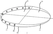
fig. 1 schematically depicts a perspective view of a luminaire according to an example embodiment;
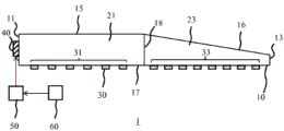
FIG. 2 schematically depicts a cross-sectional view of a luminaire according to FIG. 1;
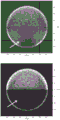
fig. 3 shows an image of a luminous output distribution achieved with a luminaire according to an example embodiment.
Fig. 4 schematically depicts a luminous output profile achieved with a luminaire in different configurations according to an example embodiment.
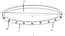
FIG. 5 schematically depicts a perspective view of a luminaire according to another example embodiment;
FIG. 6 schematically depicts a cross-sectional view of a luminaire according to FIG. 5; and
fig. 7 schematically depicts a cross-sectional view of a luminaire according to yet another example embodiment.
Detailed Description
It should be understood that the figures are merely schematic and are not drawn to scale. It should also be understood that the same reference numerals are used throughout the figures to indicate the same or similar parts.
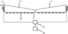
Fig. 1 schematically depicts a perspective view of an aspect of a luminaire 1 according to an embodiment, and fig. 2 schematically depicts a cross-section of the luminaire 1 along the dashed line in fig. 1. The luminaire 1 in this example embodiment comprises an elliptical plate-like light guide 10. In the context of the present application, an elliptical plate light guide is a plate light guide having an elliptical shape when viewed or projected in a direction perpendicular to a major surface (e.g., a second major surface as described below) of the plate light guide.
In at least some embodiments, the elliptical plate light guide 10 is a circular plate light guide. A circular plate light guide can be considered as a special case of an elliptical plate light guide, since it is well known from mathematics that a circle is a special case of an ellipse. The elliptical plate light guide 10 comprises a first major surface 15 opposite a second major surface 17, which surfaces act as Total Internal Reflection (TIR) surfaces of the elliptical plate light guide 10. As will be known per se, light incident on such TIR surfaces at angles below the critical angle of the TIR surface is internally reflected, which "captures" the light between the first main surface 15 and the second main surface 17, such that the light within the plate light guide 10 is guided between these surfaces.
The out-coupling element 30 may be provided on at least one of the main surfaces 15, 17 (here on the second main surface 17). The out-coupling elements 30 may be arranged in a defined pattern in order to control the position at which light is coupled out of the plate light guide 10, e.g. to control the uniformity of the luminous output of the plate light guide 10. For example, a lower density of such out-coupling elements 30 may be provided proximal to the light sources (e.g. SSL elements 40) compared to a more distal area of the plate light guide 10, in order to avoid excessive light coupling out of the plate light guide 10 proximal to such light sources. The output coupling element 30 may be provided in any suitable manner. For example, the out-coupling element 30 may be formed by roughening (e.g., texturing) the second major surface 17, such as by sand blasting, char milling, or the like. Alternatively, the out-coupling elements 30 may be formed on the second major surface 17 by positioning dedicated optical elements (e.g., 3-D elements such as lenslets, spheres, cones, prisms, etc.). Alternatively, the out-coupling element 30 may be formed as a white dot, for example by ink screen printing, ink jet printing, or the like. Many other suitable embodiments of such an output coupling element 30 will be immediately apparent to the skilled person.
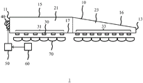
In the example embodiment shown in fig. 1 and 2, the elliptical plate light guide 10 comprises a first radial section 21 and a second radial section 23, which sections in combination form the plate light guide 10. In this embodiment, the elliptical plate light guide 10 is preferably a circular plate light guide 10, then the first and second radial sections 21, 23 are semi-circular radial sections. However, in the embodiment shown, the plate light guide is an elliptical plate light guide, but it should be understood that other shapes of radial sections are contemplated. The first radial section 21 is bounded by the constant height outer edge 11 extending between the first main surface 15 and the second main surface 17, i.e. the first radial section 21 may be a section of constant thickness. The second radial section 23 may include a tapered surface portion 16 of the first major surface 15, the tapered surface portion 16 tapering from the boundary 18 between the first radial section 21 and the second radial section 23. In other words, the thickness of the second radial section 23 decreases with increasing distance from the boundary 18. In an embodiment, the second radial section 23 is linearly tapered such that the second radial section 23 is delimited by a further edge 13 of the circular plate light guide 10 extending between the first main surface 15 and the second main surface 17, the further edge 13 decreasing in height with increasing distance from the boundary 18 along the circumference of the circular plate light guide 10.
Along the edge 11, a plurality of SSL elements 40 (e.g. LEDs) are arranged such that the luminous output of the SSL elements 40 is coupled into the first radial section 21 of the plate light guide 10 when the SSL elements 40 are engaged by the controller 50. The controller 50 is preferably adapted to individually control the respective SSL elements 40 such that the controller 50 can select which SSL elements 40 are to be deployed along the edge 11 in order to generate a specific beam profile with the luminaire 1. The SSL elements 40 may be the same SSL elements or may comprise different SSL elements, e.g. the SSL elements 40 may comprise different SSL elements arranged to produce respective luminous outputs having different spectral components, e.g. different colours of light. For example, the SSL elements 40 may include a red LED, a green LED, and a blue LED. Alternatively, the SSL elements 40 may comprise cold white LEDs, warm white LEDs and/or daylight LEDs. In such embodiments, the controller 50 may control the beam shape and/or spectral composition of the luminous output produced with the luminaire 1. Any suitable type of SSL elements 40 may be used for this purpose. The SSL elements 40 may be directly optically coupled into the plate light guide 10 through the edge 11, or alternatively may be coupled into the plate light guide 10 through the edge 11 using optical elements such as collimators, for example to ensure that substantially all light emitted by the SSL elements 40 is coupled into the plate light guide 10.
In an embodiment, the luminaire 1 further comprises a wireless communication module 60 coupled to the controller 50 for remotely controlling the controller 50. The wireless controller 60 may be adapted to communicate with a remote device (e.g., a dedicated remote controller), remote control functions programmed on a smart device such as a mobile phone, tablet computer, etc., using any suitable wireless communication protocol (e.g., Wi-Fi, bluetooth, Zigbee, NFC, mobile communication protocol, etc.), which in some embodiments may be secured using any suitable encryption technology. In this way, the luminaire 1 may be remotely configured by controlling the controller 50 through the wireless communication module 60, for example configuring the beam shape generated by the luminaire 1 (by instructing the controller 50 to select the appropriate SSL elements 40 to generate this beam shape such that it matches the required lighting function to be provided by the luminaire 1). This is particularly advantageous, for example, in outdoor lighting applications (e.g., street lamps), where the lighting profile to be produced by the street lamp may be configured to match the installation location and/or street size (e.g., the width of the street). However, such remote configurability of the luminaire 1 may be equally useful in other application areas (e.g. indoor lighting), for example to create certain aesthetic effects with the luminaire 1.
The SSL elements 40 may be mounted along the rim 11 in any suitable manner. For example, the SSL elements 40 may be mounted on an inner surface of a housing (not shown) facing the edge 11 of the luminaire 1, may be mounted on a carrier (not shown) attached to the housing or the plate light guide 10, may be directly attached to the plate light guide 10, etc. Many other suitable arrangements will be immediately apparent to the skilled person.
The first radial section 21 preferably has a constant thickness such that a substantial part of the light from the SSL elements 40 coupled into the plate light guide 10 may travel through the first radial section 21 towards the second radial section 23 by total internal reflection, wherein the emission of such light from the plate light guide 10 is facilitated by the tapered (inclined) surface portion 16 of the first main surface 15. This is at least partly because the inclined surface portion 16 reflects incident light towards the opposite second main surface 17 at an increased angle (compared to two opposite parallel surfaces) such that the probability of such reflected light rays falling onto the second main surface 17 at angles exceeding the critical angle for total internal reflection to occur is increased, thereby promoting escape of these light rays from the plate light guide 10 through the second main surface 17, i.e. the light exit surface of the plate light guide 10.
In order to achieve a substantially uniform luminous output from the light exit surface of the elliptical plate light guide 10 (e.g. a circular plate light guide), the pattern of out-coupling elements 30 may be divided into a first pattern 31 of out-coupling elements 30 on the part of the second main surface 17 of the first radial section 21 and a second pattern 33 of out-coupling elements 30 on the part of the second main surface 17 of the second radial section 23, wherein the first pattern is different from the second pattern. More specifically, the second pattern 33 may have a higher pattern density than the first pattern 31, so that the probability of light exiting the second radial section 23 is higher than the probability of light exiting the first radial section 21. In this way, the fact that there is a higher luminous flux in the first radial section 21 (since this section is proximal to the SSL elements 40) can be compensated by the difference in the patterns 31, 33 of the out-coupling elements 30, e.g. to ensure a relatively even distribution of light emission across the second main surface 17, or at least to ensure that substantially the entire main surface 17 emits light, albeit with different intensities in different regions.
Fig. 3 depicts two photographic images of a luminaire 1 according to two embodiments of the present invention, wherein in the top image the out-coupling elements 30 on the second main surface 17 are arranged based on a gaussian expansion function, wherein the gaussian angle or expansion angle on the first radial section 21 is half (5 °) the gaussian angle or expansion angle (10 °) on the second radial section 23. The second radial segment 23 is highlighted with a white arrow in each image. If this ratio (the spread angle of the out-coupling elements 30 on the second radial section 23 over the spread angle of the out-coupling elements on the first radial section 21) is about 2, a satisfactory uniform illumination of the second main surface 17 can be achieved. On the other hand, in the bottom image, the same spread angle of the gaussian spread of the out-coupling element 30 is deployed for the first radial section 21 and the second radial section 23. Thus, a major part of the light coupled into the plate light guide 10 by the edge 11 is emitted by the portion of the second main surface 17 of the first radial section 21, thus resulting in a poor uniformity of the luminous output of the luminaire 1.
Fig. 4 schematically depicts three different luminous output profiles (beam profiles) emitted from the second main surface 17 of the luminaire 1, wherein different sets of SSL elements 40 are enabled with the controller 50, according to an embodiment of the present invention. This clearly illustrates that by enabling different SSL elements along the edge 11 of the elliptical plate light guide 10, while maintaining a uniform luminous output across the second major surface 17, different (asymmetric) beam profiles can be generated.
Fig. 5 schematically depicts a perspective view of an aspect of a luminaire 1 according to another embodiment, and fig. 6 schematically depicts a cross-section of the luminaire 1 along the dashed line in fig. 5. The plate light guide 10 in this example embodiment is radially tapered from the edge portion 11 to its center, i.e. comprises a first main surface 15 that is radially tapered, such that the edge portion 11 surrounds the elliptical plate light guide 10, e.g. a circular plate light guide. In this embodiment, the SSL elements 40 may surround the plate light guide 10, i.e. may be arranged along the entire edge 11. In operation, the pairs of SSL elements 40 or the pairs of SSL element groups may be interfaced with the controller 50, e.g. in response to a configuration signal received through the wireless communication module 60, such that the luminous distribution generated with the luminaire 1 is symmetric about the dashed line in fig. 5, e.g. to achieve uniform illumination of the second main surface 17 as explained before. The pattern of out-coupling elements 30 may be arranged in any suitable pattern in order to facilitate such uniform illumination of the second main surface 17, as explained in more detail above.
In some embodiments, such as embodiments in which the luminaire 1 is designed to achieve certain aesthetic effects rather than a uniform, i.e. smooth or non-pixilated, luminous output, the luminaire 1 may further comprise at least one optical element optically coupled to the second major surface 17 in order to shape the luminous output produced by the second major surface 17. For example, as schematically depicted in fig. 7, the luminaire 1 may comprise a plurality of optical elements 70 (e.g. lenses such as toric lenses) which may for example be arranged to produce a certain light pattern, for example by way of non-limiting example concentric rings. The skilled person will immediately understand that the shape of such a light pattern is in no way limited, and that any suitable light pattern may be generated in this way.
The elliptical (e.g. circular) plate-like light guide 10 may be made in any suitable way using any suitable material or combination of materials in embodiments of the luminaire 1 of the present invention. For example, in some embodiments, the plate light guide 10 may be made of an optical grade polymer (or polymer blend) using one or more polymers, such as polycarbonate, poly (methyl methacrylate), and polyethylene terephthalate, which may facilitate manufacturing the plate light guide 10 in a cost-effective manner, e.g., using a molding technique such as, for example, injection molding. However, it should be understood that the plate light guide 10 is not limited to these example materials and manufacturing methods.
Further, while the second major surface 17 and, in some embodiments, portions of the first major surface 15 have been depicted as planar surfaces, it should be understood that this is by way of non-limiting example only, as embodiments in which these surfaces are curvilinear or curved are equally possible.
As explained before, in some embodiments, the luminaire 1 may be an outdoor luminaire, such as a street lamp, whose luminous output profile may be configurable, for example by the wireless communication module 60 remotely controlling the controller 50, such that the luminous output of the luminaire 1 may be adjusted to match the desired optical performance. However, the luminaire 1 is not limited to these applications; for example, it is also feasible that the luminaire 1 is an indoor luminaire, which may for example be configurable to achieve different aesthetic light emission output profiles by the configuration of the luminaire 1 as explained above.
It should be noted that the above-mentioned embodiments illustrate rather than limit the invention, and that those skilled in the art will be able to design many alternative embodiments without departing from the scope of the appended claims. In the claims, any reference signs placed between parentheses shall not be construed as limiting the claim. The word "comprising" does not exclude the presence of elements or steps other than those listed in a claim. The word "a" or "an" preceding an element does not exclude the presence of a plurality of such elements. The invention can be implemented by means of hardware comprising several distinct elements. In the device claim enumerating several means, several of these means may be embodied by one and the same item of hardware. The mere fact that certain measures are recited in mutually different dependent claims does not indicate that a combination of these measures cannot be used to advantage.
Claims (16)
1. A luminaire (1) comprising:
an elliptical plate-like light guide (10) comprising an edge portion (11) between a first main surface (15) and a second main surface (17), at least a portion (16) of the first main surface (15) tapering in a direction away from the edge portion (11);
a plurality of solid state lighting elements (40) arranged along the edge portion (11);
a plurality of out-coupling elements (30) arranged in a pattern on at least one of the main surfaces of the elliptical plate-like light guide (10),
the elliptical plate light guide (10) is divided into a first radial section (21) and a second radial section (23), the first radial section (21) having a constant thickness and comprising the edge portion (11); wherein the portion (16) of the first main surface (15) belongs to the second radial section (23) and the portion (16) tapers from a boundary region (18) of the second radial section (23) with the first radial section (21) to another edge portion (13) of the elliptical plate-like light guide (10),
wherein the pattern of the plurality of output coupling elements (30) comprises a first pattern (31) on the first radial section (21) and a second pattern (33) on the second radial section (23), the first pattern (31) being different from the second pattern (33).
2. The luminaire (1) according to claim 1, further comprising a controller (50), said controller (50) being arranged to individually control said solid state lighting elements (40).
3. The luminaire (1) according to claim 2, further comprising a wireless communication module (60) coupled to the controller (50) for remotely controlling the controller (50).
4. The luminaire (1) according to any one of claims 1-3, wherein the elliptical plate light guide (10) is a circular plate light guide (10).
5. The luminaire (1) according to any one of claims 1-3, wherein each radial section (21; 23) is a semi-circular section or a symmetrical semi-elliptical section.
6. The luminaire (1) according to claim 1, wherein the first pattern (31) is a first gaussian extension and the second pattern (33) is a second gaussian extension having an extension angle of twice the first gaussian extension.
7. The luminaire (1) according to any one of claims 1-3, wherein the plurality of output coupling elements (30) are arranged on the second main surface (17).
8. The luminaire (1) of any of claims 1-3, wherein the second main surface (17) is textured to form the out-coupling element (30), or wherein the out-coupling element (30) comprises a 3D optical element or a printed white dot.
9. The luminaire (1) according to any one of claims 1-3, wherein the second main surface (17) is planar.
10. The luminaire (1) according to any one of claims 1-3, wherein the elliptical plate light guide (10) comprises a polymer material selected from the group consisting of polycarbonate, polymethylmethacrylate, and polyethylene terephthalate.
11. The luminaire (1) according to any one of claims 1-3, wherein the plurality of solid state lighting elements (40) comprises solid state elements adapted to produce respective luminous outputs having different spectral compositions.
12. The luminaire (1) according to any one of claims 1-3, further comprising at least one optical element (70) optically coupled to the second main surface (17).
13. The luminaire (1) of claim 12, wherein the at least one optical element (70) comprises a plurality of lenses.
14. The luminaire (1) of claim 13, wherein the plurality of lenses are toric lenses.
15. A luminaire (1) according to any one of claims 1-3, wherein the luminaire (1) is an outdoor luminaire.
16. A luminaire (1) according to claim 15, wherein said outdoor luminaire is a street lamp.
Applications Claiming Priority (3)
| Application Number | Priority Date | Filing Date | Title |
|---|---|---|---|
| EP16186078.8 | 2016-08-29 | ||
| EP16186078 | 2016-08-29 | ||
| PCT/EP2017/068588 WO2018041470A1 (en) | 2016-08-29 | 2017-07-24 | Luminaire with light guide. |
Publications (2)
| Publication Number | Publication Date |
|---|---|
| CN109690182A CN109690182A (en) | 2019-04-26 |
| CN109690182B true CN109690182B (en) | 2021-11-26 |
Family
ID=56925981
Family Applications (1)
| Application Number | Title | Priority Date | Filing Date |
|---|---|---|---|
| CN201780053049.5A Active CN109690182B (en) | 2016-08-29 | 2017-07-24 | Luminaire with plate-like light guide |
Country Status (5)
| Country | Link |
|---|---|
| US (1) | US10830941B2 (en) |
| EP (1) | EP3504476A1 (en) |
| JP (1) | JP7080221B2 (en) |
| CN (1) | CN109690182B (en) |
| WO (1) | WO2018041470A1 (en) |
Families Citing this family (5)
| Publication number | Priority date | Publication date | Assignee | Title |
|---|---|---|---|---|
| JP7056424B2 (en) * | 2018-07-13 | 2022-04-19 | 豊田合成株式会社 | Light guide |
| US11287558B2 (en) | 2019-09-10 | 2022-03-29 | Hubbell Lighting, Inc. | Canopy luminaire |
| WO2022148743A1 (en) | 2021-01-11 | 2022-07-14 | Signify Holding B.V. | Lightguide based luminaire for disinfection and illumination |
| WO2023180416A1 (en) | 2022-03-24 | 2023-09-28 | Signify Holding B.V. | Lightguide plate with lighting gradient |
| WO2023217833A1 (en) | 2022-05-12 | 2023-11-16 | Signify Holding B.V. | Fixating a light guide without compromising the optical function |
Citations (7)
| Publication number | Priority date | Publication date | Assignee | Title |
|---|---|---|---|---|
| JP2007188681A (en) * | 2006-01-11 | 2007-07-26 | Alps Electric Co Ltd | Surface light-emitting device |
| US7969531B1 (en) * | 2007-03-08 | 2011-06-28 | Jabil Circuit, Inc. | Integrated multi-function light guide for LCD backlighting |
| US8033706B1 (en) * | 2004-09-09 | 2011-10-11 | Fusion Optix, Inc. | Lightguide comprising a low refractive index region |
| WO2012127389A1 (en) * | 2011-03-18 | 2012-09-27 | Koninklijke Philips Electronics N.V. | Light guide material, optical device and method |
| CN103499041A (en) * | 2013-10-18 | 2014-01-08 | 潘定国 | LED coaxial combination optical engine and illumination lamp thereof |
| WO2015036224A1 (en) * | 2013-09-10 | 2015-03-19 | Koninklijke Philips N.V. | A light emitting device |
| WO2015145344A1 (en) * | 2014-03-26 | 2015-10-01 | Telematics Wireless Ltd. | System and method of controlling street lights |
Family Cites Families (17)
| Publication number | Priority date | Publication date | Assignee | Title |
|---|---|---|---|---|
| JPH11183731A (en) * | 1997-12-18 | 1999-07-09 | Nissha Printing Co Ltd | Surface light emitting device |
| JP4198281B2 (en) | 1999-09-13 | 2008-12-17 | 日本ライツ株式会社 | Light guide plate and flat illumination device |
| JP2008311471A (en) * | 2007-06-15 | 2008-12-25 | Toyoda Gosei Co Ltd | Light emitting device |
| CN102047156B (en) * | 2008-05-30 | 2014-03-26 | 皇家飞利浦电子股份有限公司 | Round illumination device |
| KR101489672B1 (en) * | 2008-07-23 | 2015-02-11 | 엘지디스플레이 주식회사 | Liquid crystal display device |
| JP2012501001A (en) * | 2008-08-26 | 2012-01-12 | 潘定国 | Directional circular reflector with equilateral triangular prism and disk-shaped light having the same |
| KR20120030388A (en) * | 2009-04-24 | 2012-03-28 | 코닌클리즈케 필립스 일렉트로닉스 엔.브이. | Luminaire with functionality-enhancing structure |
| TWI471504B (en) * | 2010-10-27 | 2015-02-01 | Young Lighting Technology Corp | Flat light source module |
| CN102128377A (en) | 2011-03-21 | 2011-07-20 | 中山伟强科技有限公司 | LED light guide plate lamp assembly |
| JP2013206853A (en) | 2012-03-29 | 2013-10-07 | Toshiba Lighting & Technology Corp | Lighting system |
| ITMI20121399A1 (en) * | 2012-08-07 | 2014-02-08 | Artemide Spa | LED LIGHTING LAMP |
| US8944662B2 (en) * | 2012-08-13 | 2015-02-03 | 3M Innovative Properties Company | Diffractive luminaires |
| US9366799B2 (en) * | 2013-03-15 | 2016-06-14 | Cree, Inc. | Optical waveguide bodies and luminaires utilizing same |
| CN106574759B (en) | 2014-09-30 | 2019-05-28 | 麦克赛尔株式会社 | Lamps apparatus for vehicle |
| US20170031080A1 (en) * | 2015-07-27 | 2017-02-02 | Osram Sylvania Inc. | Edge-Lit Stepped Light Guide for Downlight Module |
| US10061073B2 (en) * | 2017-01-20 | 2018-08-28 | Oculus Vr, Llc | Circular backlight for a liquid crystal display |
| EP3369985B1 (en) * | 2017-03-02 | 2020-06-10 | Signify Holding B.V. | Luminaire with light guide |
-
2017
- 2017-07-24 CN CN201780053049.5A patent/CN109690182B/en active Active
- 2017-07-24 US US16/326,334 patent/US10830941B2/en active Active
- 2017-07-24 JP JP2019511906A patent/JP7080221B2/en active Active
- 2017-07-24 WO PCT/EP2017/068588 patent/WO2018041470A1/en active Application Filing
- 2017-07-24 EP EP17745705.8A patent/EP3504476A1/en active Pending
Patent Citations (7)
| Publication number | Priority date | Publication date | Assignee | Title |
|---|---|---|---|---|
| US8033706B1 (en) * | 2004-09-09 | 2011-10-11 | Fusion Optix, Inc. | Lightguide comprising a low refractive index region |
| JP2007188681A (en) * | 2006-01-11 | 2007-07-26 | Alps Electric Co Ltd | Surface light-emitting device |
| US7969531B1 (en) * | 2007-03-08 | 2011-06-28 | Jabil Circuit, Inc. | Integrated multi-function light guide for LCD backlighting |
| WO2012127389A1 (en) * | 2011-03-18 | 2012-09-27 | Koninklijke Philips Electronics N.V. | Light guide material, optical device and method |
| WO2015036224A1 (en) * | 2013-09-10 | 2015-03-19 | Koninklijke Philips N.V. | A light emitting device |
| CN103499041A (en) * | 2013-10-18 | 2014-01-08 | 潘定国 | LED coaxial combination optical engine and illumination lamp thereof |
| WO2015145344A1 (en) * | 2014-03-26 | 2015-10-01 | Telematics Wireless Ltd. | System and method of controlling street lights |
Also Published As
| Publication number | Publication date |
|---|---|
| JP2019536198A (en) | 2019-12-12 |
| EP3504476A1 (en) | 2019-07-03 |
| US20190219758A1 (en) | 2019-07-18 |
| US10830941B2 (en) | 2020-11-10 |
| JP7080221B2 (en) | 2022-06-03 |
| WO2018041470A1 (en) | 2018-03-08 |
| CN109690182A (en) | 2019-04-26 |
Similar Documents
| Publication | Publication Date | Title |
|---|---|---|
| CN110325787B (en) | Luminaire with light guide | |
| CN109690182B (en) | Luminaire with plate-like light guide | |
| US10416370B2 (en) | Asymmetrical light intensity distribution from luminaire | |
| JP5481223B2 (en) | Lighting device and lens sheet | |
| US10345509B2 (en) | Luminaire having an asymmetrical light distribution pattern | |
| CN103597273B (en) | In the panel have lining cave in have the edge-illuminated type illumination panel of lower shot-light | |
| US10072820B2 (en) | Tunable daylight experience using micro faceted foils | |
| CN102644864B (en) | Light-emitting device and use the ligthing paraphernalia of this light-emitting device | |
| JP2012503273A (en) | Color mixing method for consistent color quality | |
| EP2726780B1 (en) | Light guide | |
| US20190170927A1 (en) | Indirect luminaire | |
| US20200386936A1 (en) | Luminaire having an asymmetrical light distribution pattern | |
| JP7042962B2 (en) | Asymmetric light intensity distribution from luminaires | |
| WO2013150380A2 (en) | Low profile lighting module | |
| JP5785551B2 (en) | Lighting equipment and optical components | |
| CN104421841B (en) | Reflective tower, light reflection subassembly and illumination and/or signal indicating device | |
| US10801698B2 (en) | High visual comfort road and urban LED lighting | |
| TWM526038U (en) | Light guide plate and lighting device thereof | |
| CN112449671B (en) | Collimating lens and lighting device |
Legal Events
| Date | Code | Title | Description |
|---|---|---|---|
| PB01 | Publication | ||
| PB01 | Publication | ||
| SE01 | Entry into force of request for substantive examination | ||
| SE01 | Entry into force of request for substantive examination | ||
| GR01 | Patent grant | ||
| GR01 | Patent grant |