CN109591889B - Frame structure for vehicle - Google Patents
Frame structure for vehicle Download PDFInfo
- Publication number
- CN109591889B CN109591889B CN201811107736.3A CN201811107736A CN109591889B CN 109591889 B CN109591889 B CN 109591889B CN 201811107736 A CN201811107736 A CN 201811107736A CN 109591889 B CN109591889 B CN 109591889B
- Authority
- CN
- China
- Prior art keywords
- vehicle
- cross member
- bracket
- cross
- stabilizer
- Prior art date
- Legal status (The legal status is an assumption and is not a legal conclusion. Google has not performed a legal analysis and makes no representation as to the accuracy of the status listed.)
- Active
Links
Images


Classifications
-
- B—PERFORMING OPERATIONS; TRANSPORTING
- B62—LAND VEHICLES FOR TRAVELLING OTHERWISE THAN ON RAILS
- B62D—MOTOR VEHICLES; TRAILERS
- B62D21/00—Understructures, i.e. chassis frame on which a vehicle body may be mounted
- B62D21/02—Understructures, i.e. chassis frame on which a vehicle body may be mounted comprising longitudinally or transversely arranged frame members
-
- B—PERFORMING OPERATIONS; TRANSPORTING
- B62—LAND VEHICLES FOR TRAVELLING OTHERWISE THAN ON RAILS
- B62D—MOTOR VEHICLES; TRAILERS
- B62D25/00—Superstructure or monocoque structure sub-units; Parts or details thereof not otherwise provided for
- B62D25/08—Front or rear portions
- B62D25/082—Engine compartments
Abstract
The invention aims to provide a vehicle frame structure capable of effectively improving rigidity at a front part of a vehicle. A vehicle frame structure (100) for a vehicle front section is characterized by comprising a pair of side frames (102a, 102b) extending in the vehicle front-rear direction and spaced apart from each other in the vehicle width direction, a 1 st cross member (104) erected near the front ends of the pair of side frames (102a, 102b), a 2 nd cross member (108) erected on the pair of side frames (102a, 102b) at the vehicle rear side of the 1 st cross member (104), and a 1 st cross member bracket (124) and a 2 nd cross member bracket (126) erected on the 1 st cross member (104) and the 2 nd cross member (108).
Description
Technical Field
The present invention relates to a vehicle frame structure.
Background
Among frame structures of a vehicle, a structure in which a plurality of cross members are bridged between a pair of side frames extending in a vehicle front-rear direction as shown in fig. 10 of patent document 1, for example, is called a ladder frame (ladder frame). Since the ladder frame has high vehicle rigidity, it is often used in off-road vehicles and the like that travel in unpaved places.
Documents of the prior art
Patent document
Patent document 1: japanese Utility model No. 2526165
Disclosure of Invention
Problems to be solved by the invention
In vehicles having a ladder frame structure, further improvement in rigidity is now desired. In particular, a traveling vehicle is likely to receive a torsional load by the left and right front wheels, and the rigidity of the front portion of the vehicle is effectively improved.
In view of the above problems, an object of the present invention is to provide a vehicle frame structure that can effectively improve rigidity in a vehicle front portion.
Means for solving the problems
In order to solve the above problem, a typical structure of a vehicle frame structure according to the present invention is a vehicle frame structure of a vehicle front portion, the vehicle frame structure including: the vehicle body structure includes a pair of side frames extending in a vehicle front-rear direction and spaced apart from each other in a vehicle width direction, a 1 st cross member erected near front ends of the pair of side frames, a 2 nd cross member erected on the pair of side frames at a vehicle rear side of the 1 st cross member, and one or more cross member brackets erected on the 1 st cross member and the 2 nd cross member.
ADVANTAGEOUS EFFECTS OF INVENTION
According to the present invention, it is possible to provide a vehicle frame structure capable of effectively improving rigidity in a vehicle front portion.
Drawings
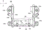
Fig. 1(a) is a view of the vehicle frame structure 100 as viewed from above, and fig. 1(b) is a view of the vehicle frame structure 100 of fig. 1(a) as viewed from below.
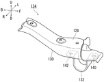
Fig. 2(a) is a perspective view showing the 1 st beam 104 of fig. 1(a) alone, and fig. 2(b) is a perspective view showing the 1 st beam bracket 124 of fig. 1(a) alone.
Fig. 3 is a sectional view a-a of the vehicle frame structure of fig. 1 (a).
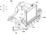
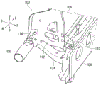
Fig. 4(a) is a view of the vehicle frame structure 100 as viewed from diagonally above the right side of the vehicle, and fig. 4(b) is an enlarged view of the vicinity of the base of the radiator 106 in fig. 4 (a).
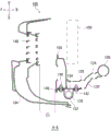
Fig. 5(a) is a view of the vicinity of the radiator sub-frame 112 as viewed from above, and fig. 5(b) is a perspective view of the radiator sub-frame 112 and the like of fig. 4(b) as viewed obliquely from below on the right side of the vehicle.
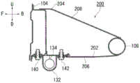
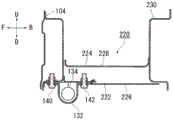
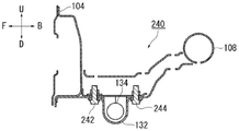
Fig. 6(a) is a view showing a beam bracket 200 according to modification 1, fig. 6(b) is a view showing a beam bracket 220 according to modification 2, and fig. 6(c) is a view showing a beam bracket 240 according to modification 3.
Description of the reference numerals
100. A frame structure for a vehicle; 102a, a side frame on the right side of the vehicle; 102b, a vehicle left side frame; 104. the 1 st cross beam; 104a, the front side member of the 1 st cross member; 104b, the rear member of the 1 st cross member; 106. a heat sink; 108. a 2 nd cross beam; 110. a front side heat sink bracket; 112. a radiator sub-frame; 114. a rear side heat sink bracket; 116. an intercooler bracket; 118. an intercooler; 120. a vehicle body mount; 122. a coil spring support; 124. 1 st beam bracket; 126. a 2 nd beam bracket; 128. an upper member of the beam bracket; 130. a lower member of the beam bracket; 132. a stabilizer mount; 134. a stabilizer; 136. a central region of the stabilizer; 138a, the curved region of the right side of the vehicle; 138b, the curved region of the left side of the vehicle; 140. a mounting point of the front side; 142. a mounting point at the rear side; 144. a front bumper; 146. 1 st beam leading edge; 148. a bumper mesh; 200. the cross beam bracket of modification 1; 202. a lower member of a cross member bracket according to modification 1; 204. an upper member of a cross member bracket according to modification 1; 206. a bottom surface of the lower member; 208. an upper surface of the upper member; 220. the cross beam bracket of modification 2; 222. a lower member of a cross member bracket according to modification 2; 224. an upper member of a cross member bracket according to modification 2; 226. a bottom surface of the lower member; 228. an upper surface of the upper member; 230. the 2 nd cross member of the modification; 240. the cross beam bracket of modification 3; 242. a mounting point of the front side; 244. a mounting point at the rear side; e1, gap.
Detailed Description
A vehicle frame structure according to an embodiment of the present invention is a vehicle frame structure of a vehicle front portion, the vehicle frame structure including: a pair of side frames extending in a vehicle front-rear direction and spaced apart from each other in a vehicle width direction; a 1 st cross member erected at the front ends of the pair of side frames; a 2 nd cross member that is erected on the pair of side frames at the vehicle rear side of the 1 st cross member; and one or more cross beam brackets, the one or more cross beam brackets mounted to the No. 1 cross beam and the No. 2 cross beam.
According to the above configuration, the stress that has conventionally occurred at the joint between the 1 st cross member and the side frame can be dispersed to the 2 nd cross member by the cross member bracket. Therefore, according to the above configuration, the torsional rigidity of the vehicle can be improved, and vibrations and the like during traveling can be further suppressed.
The plurality of cross members may be disposed on the left and right sides with respect to the vehicle center in the vehicle width direction. According to this structure, the torsional rigidity of the vehicle can be improved uniformly in the vehicle width direction.
The vehicle frame structure may further include a stabilizer having a central region extending in the vehicle width direction, the central region of the stabilizer intersecting the cross member bracket, and the stabilizer may be attached to the cross member bracket at attachment points in front and rear of the intersection.
According to the above configuration, the mounting rigidity of the stabilizer can be further improved by mounting the mounting points on the front and rear sides of the stabilizer to the cross member bracket.
The stabilizer may be attached to the cross member bracket such that the center region is located further to the vehicle rear side than the front edge of the 1 st cross member.
According to the above configuration, by disposing the stabilizer at the position rearward of the front edge of the 1 st cross member, a gap can be secured between the 1 st cross member and the front bumper in front thereof. This gap serves as a buffer region when the vehicle contacts a pedestrian, a so-called pedestrian protection stroke region, and therefore can exhibit a pedestrian protection effect. Further, by securing the gap at this position, the degree of freedom in designing the exterior member such as the front bumper can be improved.
At least one of the mounting points for the stabilizer may be provided in the cross member bracket in a region overlapping with the 1 st cross member.
According to the above configuration, by attaching at least one of the front and rear attachment points of the stabilizer to both the beam bracket and the 1 st beam, not only can the attachment rigidity of the stabilizer be improved, but also the coupling between the beam bracket and the 1 st beam becomes strong, and the stress dispersion can be promoted, and the torsional rigidity of the vehicle can be further improved.
The bottom surface of the cross member bracket may extend linearly in the vehicle front-rear direction when viewed from the side of the vehicle.
According to the above configuration, when the stress dispersion from the 1 st beam to the beam bracket occurs, the beam bracket is less likely to be deformed.
The vehicle frame structure may further include a radiator support that is provided between at least one of the pair of side frames and the beam bracket closest to the at least one side frame and is bridged between the 1 st beam and the 2 nd beam, and the radiator support is to be attached to a predetermined radiator.
According to the above configuration, the radiator can be attached with high rigidity in a range of high rigidity surrounded by the cross bracket, the side frame, and the like.
[ examples ] A method for producing a compound
Suitable embodiments of the present invention are described in detail below with reference to the appended drawings. Dimensions, materials, and other specific numerical values shown in such embodiments are merely examples for facilitating understanding of the present invention, and are not intended to limit the present invention unless otherwise specified. In the present specification and the drawings, elements having substantially the same function and configuration are denoted by the same reference numerals, and overlapping description thereof is omitted, and elements not directly related to the present invention are not shown.
Fig. 1(a) and 1(b) show a vehicle frame structure 100 according to embodiment 1 of the present invention. Fig. 2(a) and 2(b) are views showing the 1 st beam 104 and the beam bracket 124 in fig. 1 (a). In fig. 1(a), 1(b) and other drawings of the present application, the vehicle longitudinal direction is illustrated by arrows f (forward) and b (backward), the vehicle lateral direction is illustrated by arrows l (left) and r (right), and the vehicle vertical direction is illustrated by arrows u (upward) and d (downward), respectively.
Fig. 1(a) shows a vehicle frame structure 100 as viewed from above. The vehicle frame structure 100 is a framework of a vehicle located at the front of the vehicle, and includes a pair of side frames 102a and 102b, and a plurality of cross members such as a 1 st cross member 104 and a 2 nd cross member 108. In the vehicle frame structure 100, the rigidity of the entire structure including the side frames 102a and 102b and the 1 st and 2 nd cross members 104 and 108 is improved.
The pair of side frames 102a and 102b included in the vehicle frame structure 100 are members extending in the vehicle front-rear direction, and are provided apart from each other in the vehicle width direction. A vehicle body mount 120a and a vehicle body mount 120b are provided on the outer sides of the side frames 102a and 102b near the front ends thereof, and coil spring brackets 122a and 122b are provided on the rear sides thereof. The vehicle body mount 120a and the vehicle body mount 120b support the vehicle body from below, and the coil spring holder 122a and the coil spring holder 122b support the coil spring of the suspension from above.
The 1 st cross member 104 is erected inside the front end of the side frame 102a in the vehicle width direction. Fig. 2(a) is a perspective view showing the 1 st cross member 104 of fig. 1(a) alone. The 1 st cross member 104 is a structure in which a front side member 104a in the shape of a wall on the vehicle front side is joined to a rear side member 104b bulging rearward on the vehicle rear side, and which has a closed cross section and is high in bending rigidity. The 1 st cross member 104 is joined to the side frames 102a and 102b (see fig. 1 a) by welding.
As shown in fig. 1(a), a 2 nd cross member 108 is provided between the side frames 102a and 102b at a position rearward of the 1 st cross member 104 in the vehicle. In the present embodiment, the 2 nd cross member 108 is a substantially tubular member having a circular closed cross section, has high bending rigidity, and extends in a slightly curved shape in the vicinity of the center in the vehicle width direction. The 2 nd cross member 108 is inserted into a mounting hole provided in the side frame 102a and joined to the side frame 102a (see fig. 4 a). The 2 nd cross member 108 does not need to have a tubular structure, and a structure having a rectangular open cross section similar to a general cross member can also obtain the same effect.
A plurality of cross member brackets are provided to span the 1 st cross member 104 and the 2 nd cross member 108 in the vehicle front-rear direction. In the present embodiment, two in total are provided, namely, a 1 st cross bracket 124 on the right side in the vehicle width direction and a 2 nd cross bracket 126 on the left side in the vehicle width direction. Of the cross brackets, the 1 st cross bracket 124 on the vehicle right side is slightly longer than the 2 nd cross bracket 126 in the vehicle front-rear direction, but has substantially the same structure.
Fig. 2(b) is a perspective view showing the 1 st cross member bracket 124 of fig. 1(a) alone. The 1 st cross member bracket 124 is a member that extends slightly curved in the vehicle front-rear direction, and has a structure with high bending rigidity in which an upper member 128 and a lower member 130 are joined to each other to form a closed cross section.
According to the configuration shown in fig. 1(a), torsional stress that has conventionally occurred at the joint between the side frame 102a, the side frame 102b, and the 1 st cross member 104 due to input from the suspension of the front wheel can be dispersed to the 2 nd cross member 108 by the 1 st cross member bracket 124 and the 2 nd cross member bracket 126. That is, according to the present embodiment, the torsional rigidity of the vehicle is improved, and the vibration and the like during traveling can be further suppressed.
In particular, in the present embodiment, the 1 st cross bracket 124 and the 2 nd cross bracket 126 are disposed on the left and right sides with respect to the vehicle center in the vehicle width direction. According to this structure, the torsional rigidity of the front portion of the vehicle can be effectively improved in the vehicle width direction. In this case, the 1 st cross bracket 124 and the 2 nd cross bracket 126 may be disposed at positions symmetrical to the vehicle center, whereby the torsional rigidity of the vehicle can be effectively improved uniformly in the vehicle width direction. Further, the vehicle frame structure 100 does not necessarily have a plurality of cross member brackets, and by erecting one cross member bracket between the 1 st cross member 104 and the 2 nd cross member 108, the rigidity of the vehicle can be improved.
Fig. 1(b) is a view showing the vehicle frame structure 100 of fig. 1(a) as viewed from below. The vehicle frame structure 100 also has a stabilizer 134. The stabilizer 134 is also called a stabilizer bar, is a member for suppressing the inclination of the vehicle, and is mounted on left and right suspensions. The stabilizer 134 has a central region 136 extending in the vehicle width direction, and a curved region 138a and a curved region 138b that curve toward the suspension from both ends of the central region 136 and toward the vehicle rear.
Refer to fig. 2(b) again. A stabilizer mount 132 for mounting a stabilizer 134 is provided at the lower side of the 1 st beam bracket 124. The stabilizer attachment 132 projects in a U-letter shape toward the vehicle lower side, and holds the stabilizer 134 to support the stabilizer 134.
As shown in fig. 1(b), the central region 136 of the stabilizer 134 intersects the 1 st and 2 nd beam brackets 124, 126, and the stabilizer 134 is attached to each beam bracket at attachment points on both front and rear sides of the intersection, for example, an attachment point 140 and an attachment point 142 on the 1 st beam bracket 124. Since each beam bracket is erected on the 1 st beam 104 and the 2 nd beam 108 and has high rigidity, the mounting rigidity of the stabilizer 134 can be improved.
Fig. 3 is a sectional view a-a of the vehicle frame structure 100 of fig. 1 (a). Also shown in fig. 3 is a front bumper 144 and a radiator 106 illustrated by dashed lines. The front side of the lower member 130 of the 1 st beam bracket 124 is formed in a flange shape, and the lower member 130 is joined to the bottom surface of the 1 st beam 104 by welding, bolting, or the like. The front side of the upper member 128 is also joined to the rear surface of the 1 st cross member 104 by welding or the like.
The mounting points 140, 142 of the stabilizer mount 132 are implemented by bolts and bolt holes. In particular, the vehicle front side mounting point 140 is provided in a region of the 1 st cross member bracket 124 that overlaps the 1 st cross member 104 when viewed in the vertical direction (see fig. 1(b)), and fastens the stabilizer mount 132, the 1 st cross member bracket 124, and the 1 st cross member 104 together. The rear mounting point 142 is used to fasten the stabilizer mount 132 and the 1 st cross-beam bracket 124 together.
According to the above-described mounting point 140, by mounting the stabilizer 134 on both the 1 st cross member bracket 124 and the 1 st cross member 104, not only the mounting rigidity of the stabilizer 134 can be improved, but also the coupling between the 1 st cross member bracket 124 and the 1 st cross member 104 can be strengthened, and the stress dispersion can be promoted, thereby further improving the torsional rigidity of the vehicle.
The stabilizer 134 is attached to the 1 st cross member bracket 124 by the stabilizer mount 132 described above such that the center region 136 is positioned further to the vehicle rear side than the front edge 146 of the 1 st cross member 104. By disposing the stabilizer 134 rearward of the front edge 146 of the 1 st cross member 104, a gap E1 is ensured between the 1 st cross member 104 and the front bumper 144 in front thereof (for example, a bumper net 148 protruding toward the vehicle rear side in the front bumper 144). The gap E1 serves as a buffer region when the vehicle contacts a pedestrian, a so-called pedestrian protection stroke region, and therefore can exert a pedestrian protection effect. Further, by securing the gap E1 at this position, the degree of freedom in designing the exterior member such as the front bumper 144 can be improved.
Fig. 4(a) and 4(b) are perspective views of the vehicle frame structure 100 of fig. 1 (a). In fig. 4(a), the vehicle frame structure 100 is viewed from obliquely above the right side of the vehicle. In the vehicle frame structure 100, the radiator 106, which is a heavy object, can be sufficiently fixed.
Fig. 4(b) is an enlarged view of the vicinity of the base of the heat sink 106 in fig. 4 (a). In the present embodiment, the radiator 106 is supported with respect to the 1 st cross member 104 and the 2 nd cross member 108 rearward thereof by a front radiator support 110, a radiator sub-frame 112, and a rear radiator support 114 in this order from the front of the vehicle. The front radiator support 110 is joined to the upper portion of the 1 st cross member 104, and the rear radiator support 114 is joined to the 2 nd cross member 108. The radiator sub-frame 112 is joined to the front radiator support 110 and the rear radiator support 114 so as to be bridged between the front radiator support 110 and the rear radiator support 114 in the vehicle longitudinal direction.
Fig. 5(a) and 5(b) show the vicinity of the radiator sub-frame 112 of fig. 4(b) from other directions. Fig. 5(a) is a view of the vicinity of the radiator sub-frame 112 as viewed from above. The aforementioned components such as the radiator sub-frame 112 are mounted on the 1 st cross member 104 and the 2 nd cross member 108 between the side frame 102a and the 1 st cross member bracket 124 located at the closest position to the side frame 102 a. Thus, in the vehicle frame structure 100, the radiator 106 can be supported with high rigidity.
Fig. 5(b) is a perspective view of the radiator sub-frame 112 and the like in fig. 4(b) as viewed obliquely from below on the right side of the vehicle. An intercooler 118 for reducing the temperature of intake air of a turbo (supercharger) is also mounted on the radiator sub-frame 112 via an intercooler bracket 116. The radiator sub-frame 112 is erected on the 1 st cross member 104 and the 2 nd cross member 108 and is provided with high rigidity, and therefore can also appropriately support the intercooler 118.
As described above, the front radiator support 110, the radiator sub-frame 112, and the rear radiator support 114 in fig. 5(a) are erected between the side frame 102a and the 1 st cross member bracket 124 closest to the side frame 102a on the 1 st cross member 104 and the 2 nd cross member 108. This range is a very rigid portion, and therefore, shearing of the welded portion and the like can be effectively prevented, and the radiator 106 and the intercooler 118, which are load-bearing objects, can be firmly supported and prevented from falling off. Therefore, even when an impact is applied to the vehicle from the front, the displacement of the radiator 106 and the like toward the rear of the vehicle can be suppressed, and the occupant can be protected.
(modification example)
Fig. 6(a), 6(b), and 6(c) are views showing modifications of the 1 st cross member bracket 124 in fig. 3. The beam bracket of each modification is not limited by the installation position, and can be applied to any of the 1 st beam bracket 124 and the 2 nd beam bracket 126 of fig. 1(a) and 1 (b). Hereinafter, the same components as those described are denoted by the same reference numerals, and the description thereof is omitted. Note that, even if a component having the same name as the component already described is given a different reference numeral, the component is regarded as having the same function unless otherwise specified.
Fig. 6(a) is a view showing a cross beam bracket 200 according to modification 1. In the cross member bracket 200, the front side of the lower member 202 is joined to the bottom surface of the 1 st cross member 104, and the front side of the upper member 204 is joined to the top surface of the 1 st cross member 104. Further, the bottom surface 206 of the lower member 202 is configured to extend linearly in the vehicle front-rear direction from the bottom surface of the 1 st cross member 104 to the 2 nd cross member 108 when viewed from the side of the vehicle. The upper surface 208 of the upper member 204 also has a structure extending linearly and obliquely from the top surface of the 1 st cross member 104 to the 2 nd cross member 108.
The beam bracket 200 has a structure in which bent portions are further reduced from the lower member 202 and the upper member 204. With this beam bracket 200, when stress dispersion occurs from the 1 st beam 104 to this beam bracket 200, deformation can be made difficult to occur, and the load can be efficiently transmitted from the 1 st beam 104 to the 2 nd beam 108.
Fig. 6(b) is a view showing a beam bracket 220 according to modification 2. Here, the 2 nd beam 230 shown in fig. 6(b) has a similar configuration to the 1 st beam 104 having a flat surface, unlike the circular 2 nd beam 108 of fig. 6 (a). Therefore, the beam bracket 220 has the following structure: not only the bottom surface 226 of the lower member 222 but also the upper surface 228 of the upper member 224 linearly extend in the vehicle front-rear direction.
The upper side member 224 of the beam bracket 220 spans the rear surface of the 1 st beam 104 and the front surface of the 2 nd beam 230 and engages the rear surface of the 1 st beam 104 and the front surface of the 2 nd beam 230. The lower member 222 spans the bottom surface of the 1 st beam 104 and the bottom surface of the 2 nd beam 230 and is joined to the bottom surface of the 1 st beam 104 and the bottom surface of the 2 nd beam 230. In the beam bracket 220, the bending portion is also cut from the upper member 224 and the lower member 222, so that deformation is less likely to occur, and the load can be efficiently transmitted from the 1 st beam 104 to the 2 nd beam 230.
Fig. 6(c) is a view showing a beam bracket 240 according to modification 3. In the beam bracket 240, a front mounting point 242 of the stabilizer mount 132 is located rearward of the 1 st beam 104, and is fastened only to the beam bracket 240 together with a rear mounting point 244. With this configuration, the stabilizer 134 is disposed further toward the vehicle rear side than the 1 st cross member 104, and the clearance E1, which is the stroke region for pedestrian protection shown in fig. 3, can be ensured even more.
While the preferred embodiments of the present invention have been described above with reference to the accompanying drawings, it is needless to say that the present invention is not limited to such examples. It is clear that those skilled in the art can conceive various modifications and variations within the scope of the claims and that these modifications and variations also fall within the technical scope of the present invention.
Industrial applicability
The present invention can be used for a vehicle frame structure.
Claims (5)
1. A vehicle frame structure at a front portion of a vehicle, the vehicle frame structure comprising:
a pair of side frames extending in a vehicle front-rear direction and spaced apart from each other in a vehicle width direction;
a 1 st cross member erected at the front ends of the pair of side frames;
a 2 nd cross member that is erected on the pair of side frames at the vehicle rear side of the 1 st cross member;
one or more beam brackets which are erected on the 1 st beam and the 2 nd beam; and
a stabilizer having a central region extending in a vehicle width direction,
the central region of the stabilizer intersects the cross beam bracket, the stabilizer being mounted to the cross beam bracket at mounting points forward and rearward of the intersection,
at least one of the mounting points for mounting the stabilizer to the cross-beam bracket is provided in a region of the cross-beam bracket overlapping with the 1 st cross-beam.
2. The frame structure for a vehicle according to claim 1,
the plurality of beam brackets are arranged on the left and right sides with respect to the vehicle center in the vehicle width direction.
3. The frame configuration for a vehicle according to claim 1 or 2,
the stabilizer is attached to the cross member bracket at a position rearward of the front edge of the 1 st cross member in the central region.
4. The frame configuration for a vehicle according to claim 1 or 2,
the bottom surface of the cross member bracket extends linearly in the vehicle front-rear direction when viewed from the side of the vehicle.
5. The frame configuration for a vehicle according to claim 1 or 2,
the vehicle frame structure further includes a radiator support that is provided between the side frame and the cross member bracket closest to the side frame and that is bridged between the 1 st cross member and the 2 nd cross member, and that is used for mounting a radiator.
Applications Claiming Priority (2)
| Application Number | Priority Date | Filing Date | Title |
|---|---|---|---|
| JP2017193496A JP6977461B2 (en) | 2017-10-03 | 2017-10-03 | Vehicle frame structure |
| JP2017-193496 | 2017-10-03 |
Publications (2)
| Publication Number | Publication Date |
|---|---|
| CN109591889A CN109591889A (en) | 2019-04-09 |
| CN109591889B true CN109591889B (en) | 2021-12-14 |
Family
ID=65727730
Family Applications (1)
| Application Number | Title | Priority Date | Filing Date |
|---|---|---|---|
| CN201811107736.3A Active CN109591889B (en) | 2017-10-03 | 2018-09-21 | Frame structure for vehicle |
Country Status (4)
| Country | Link |
|---|---|
| JP (1) | JP6977461B2 (en) |
| CN (1) | CN109591889B (en) |
| DE (1) | DE102018124202B4 (en) |
| FR (1) | FR3071807B1 (en) |
Citations (7)
| Publication number | Priority date | Publication date | Assignee | Title |
|---|---|---|---|---|
| JP2000142054A (en) * | 1998-11-16 | 2000-05-23 | Mazda Motor Corp | Stabilizer attaching bracket structure |
| DE102011085757A1 (en) * | 2010-11-27 | 2012-05-31 | Ford Global Technologies, Llc | ENERGY MANAGEMENT STRUCTURE |
| DE102011103090A1 (en) * | 2011-05-25 | 2012-11-29 | Thyssenkrupp Steel Europe Ag | Vehicle body and its use |
| CN103183060A (en) * | 2011-12-27 | 2013-07-03 | 本田技研工业株式会社 | Vehicle-body front structure |
| CN103481951A (en) * | 2012-06-12 | 2014-01-01 | 三菱自动车工业株式会社 | Vehicle body front structure |
| CN103738404A (en) * | 2013-11-29 | 2014-04-23 | 天津博信汽车零部件有限公司 | Frame and vehicle comprising same |
| CN204296387U (en) * | 2014-12-04 | 2015-04-29 | 北京汽车研究总院有限公司 | Automobile front suspension assembly and automobile |
Family Cites Families (7)
| Publication number | Priority date | Publication date | Assignee | Title |
|---|---|---|---|---|
| JP2526165B2 (en) | 1990-07-26 | 1996-08-21 | 三菱自動車エンジニアリング株式会社 | Pallet positioning jig |
| JP3346697B2 (en) * | 1996-02-22 | 2002-11-18 | ダイハツ工業株式会社 | Car body front structure |
| JPH10230869A (en) * | 1997-02-19 | 1998-09-02 | Daihatsu Motor Co Ltd | Car body front part structure of automobile |
| JP3526537B2 (en) * | 1998-12-21 | 2004-05-17 | 享栄エンジニアリング株式会社 | Front body structure of vehicle |
| US20140062129A1 (en) * | 2012-09-04 | 2014-03-06 | GM Global Technology Operations LLC | Impact deflection and absorption structure |
| DE102013011562A1 (en) * | 2013-07-11 | 2015-01-15 | Audi Ag | Subframe for a motor vehicle |
| JP6241259B2 (en) * | 2013-12-19 | 2017-12-06 | 三菱自動車工業株式会社 | Body structure |
-
2017
- 2017-10-03 JP JP2017193496A patent/JP6977461B2/en active Active
-
2018
- 2018-09-21 CN CN201811107736.3A patent/CN109591889B/en active Active
- 2018-09-28 FR FR1859022A patent/FR3071807B1/en active Active
- 2018-10-01 DE DE102018124202.6A patent/DE102018124202B4/en active Active
Patent Citations (7)
| Publication number | Priority date | Publication date | Assignee | Title |
|---|---|---|---|---|
| JP2000142054A (en) * | 1998-11-16 | 2000-05-23 | Mazda Motor Corp | Stabilizer attaching bracket structure |
| DE102011085757A1 (en) * | 2010-11-27 | 2012-05-31 | Ford Global Technologies, Llc | ENERGY MANAGEMENT STRUCTURE |
| DE102011103090A1 (en) * | 2011-05-25 | 2012-11-29 | Thyssenkrupp Steel Europe Ag | Vehicle body and its use |
| CN103183060A (en) * | 2011-12-27 | 2013-07-03 | 本田技研工业株式会社 | Vehicle-body front structure |
| CN103481951A (en) * | 2012-06-12 | 2014-01-01 | 三菱自动车工业株式会社 | Vehicle body front structure |
| CN103738404A (en) * | 2013-11-29 | 2014-04-23 | 天津博信汽车零部件有限公司 | Frame and vehicle comprising same |
| CN204296387U (en) * | 2014-12-04 | 2015-04-29 | 北京汽车研究总院有限公司 | Automobile front suspension assembly and automobile |
Also Published As
| Publication number | Publication date |
|---|---|
| CN109591889A (en) | 2019-04-09 |
| JP6977461B2 (en) | 2021-12-08 |
| DE102018124202A1 (en) | 2019-04-04 |
| JP2019064506A (en) | 2019-04-25 |
| FR3071807A1 (en) | 2019-04-05 |
| DE102018124202B4 (en) | 2022-08-25 |
| FR3071807B1 (en) | 2024-01-19 |
Similar Documents
| Publication | Publication Date | Title |
|---|---|---|
| JP5974475B2 (en) | Front subframe structure of automobile | |
| JP4029301B2 (en) | Vehicle under-run protector mounting structure | |
| EP2749478B1 (en) | Structure for front section of vehicle body | |
| JP4346317B2 (en) | Auto body front structure | |
| US20070176443A1 (en) | Automobile front body structure | |
| WO2017065086A1 (en) | Structure for side part of body of vehicle | |
| US10005412B2 (en) | Vehicle front portion structure | |
| US8020925B2 (en) | Front structure of cab-over type vehicle | |
| JP5870673B2 (en) | Front subframe structure of automobile | |
| JP5949044B2 (en) | Front subframe structure | |
| JP2008195094A (en) | Front body structure of vehicle | |
| CN112455542B (en) | Auxiliary frame for vehicle | |
| KR102359711B1 (en) | Sub frame apparatus for vehicle | |
| CN110949517B (en) | Rear auxiliary frame structure | |
| JP4601837B2 (en) | Battery bracket structure | |
| CN111746648A (en) | Subframe for vehicle | |
| EP3025935B1 (en) | Suspension member | |
| CN109591889B (en) | Frame structure for vehicle | |
| JP4069605B2 (en) | Lower body structure of the vehicle | |
| KR101682810B1 (en) | Half type sub frame for automobile | |
| JP6754006B2 (en) | Torque rod mounting structure | |
| JP2007131187A (en) | Front section vehicle body structure of automobile | |
| CN109552423B (en) | Front body structure of vehicle | |
| CN112789213B (en) | Subframe structure | |
| KR102359712B1 (en) | Sub frame for vehicle |
Legal Events
| Date | Code | Title | Description |
|---|---|---|---|
| PB01 | Publication | ||
| PB01 | Publication | ||
| SE01 | Entry into force of request for substantive examination | ||
| SE01 | Entry into force of request for substantive examination | ||
| GR01 | Patent grant | ||
| GR01 | Patent grant |