CN109578552B - From gear structure of taking oil ring - Google Patents
From gear structure of taking oil ring Download PDFInfo
- Publication number
- CN109578552B CN109578552B CN201910067621.4A CN201910067621A CN109578552B CN 109578552 B CN109578552 B CN 109578552B CN 201910067621 A CN201910067621 A CN 201910067621A CN 109578552 B CN109578552 B CN 109578552B
- Authority
- CN
- China
- Prior art keywords
- oil
- proof ring
- ring
- groove
- gear
- Prior art date
- Legal status (The legal status is an assumption and is not a legal conclusion. Google has not performed a legal analysis and makes no representation as to the accuracy of the status listed.)
- Active
Links
Images


Classifications
-
- F—MECHANICAL ENGINEERING; LIGHTING; HEATING; WEAPONS; BLASTING
- F16—ENGINEERING ELEMENTS AND UNITS; GENERAL MEASURES FOR PRODUCING AND MAINTAINING EFFECTIVE FUNCTIONING OF MACHINES OR INSTALLATIONS; THERMAL INSULATION IN GENERAL
- F16H—GEARING
- F16H55/00—Elements with teeth or friction surfaces for conveying motion; Worms, pulleys or sheaves for gearing mechanisms
- F16H55/02—Toothed members; Worms
- F16H55/17—Toothed wheels
-
- F—MECHANICAL ENGINEERING; LIGHTING; HEATING; WEAPONS; BLASTING
- F16—ENGINEERING ELEMENTS AND UNITS; GENERAL MEASURES FOR PRODUCING AND MAINTAINING EFFECTIVE FUNCTIONING OF MACHINES OR INSTALLATIONS; THERMAL INSULATION IN GENERAL
- F16H—GEARING
- F16H57/00—General details of gearing
- F16H57/04—Features relating to lubrication or cooling or heating
Landscapes
- Engineering & Computer Science (AREA)
- General Engineering & Computer Science (AREA)
- Mechanical Engineering (AREA)
- General Details Of Gearings (AREA)
- Gears, Cams (AREA)
Abstract
The invention provides a gear structure with an oil-proof ring, which comprises a gear part and a cylindrical oil-proof ring, wherein a central shaft of the oil-proof ring and a central shaft of the gear part are on the same straight line, the oil-proof ring is connected with the gear part, and a reserved connecting hole is formed in the middle of the gear structure with the oil-proof ring. The gear structure with the oil-proof ring has the advantages of being simple and reasonable in structure, capable of effectively preventing grease loss, improving the utilization rate of the grease, effectively improving the lubricating property of the gear part and avoiding the slipping phenomenon caused by the grease.
Description
Technical Field
The invention relates to the field of gears, in particular to a gear structure with an oil-proof ring.
Background
The gear is under high-speed moving operating condition, must paint high temperature antifriction lubricating grease at tooth portion, because rotatory centrifugal force phenomenon, the grease can be along tooth's socket throw away skew gear engagement position and cause the grease to run off for the utilization ratio of grease itself can not be ensured, the grease of throwing away simultaneously can drop to drive ring and transmission notch, cause the position that need not use the grease and should lead to the fact side effect such as skidding for the grease that drops, reliability and the life of product when the product that can't guarantee to use the gear uses.
Disclosure of Invention
It is an object of the present invention to provide a gear structure with an oil-tight ring, which solves one or more of the above mentioned problems of the prior art.
The invention provides a gear structure with an oil-proof ring, which comprises a gear part and a cylindrical oil-proof ring, wherein a central shaft of the oil-proof ring and a central shaft of the gear part are on the same straight line, the oil-proof ring is connected with the gear part, the gear structure with the oil-proof ring is vertically placed, the bottom of the oil-proof ring is connected with the top of the gear part, the oil-proof ring and the gear part are vertically projected, the projection of the oil-proof ring covers the projection of the gear part, and a reserved connecting hole is formed in the middle of the gear structure with the oil-proof ring.
Wherein, the oil-proof ring and the gear part are integrally cast and molded.
The gear part forms a projection A on the oil-proof ring by utilizing a vertical projection technology, and the part of the outer side edge of the oil-proof ring, which exceeds the projection A, is a retainer ring.
The bottom of the gear part is provided with a circular groove, reinforcing ribs are arranged in the groove, the tops of the reinforcing ribs are connected with the bottom of the gear part, the reinforcing ribs comprise eight strip-shaped first reinforcing ribs which are circumferentially and uniformly distributed by taking the reserved connecting holes as centers, and an arc-shaped second reinforcing rib is arranged between every two adjacent first reinforcing ribs and is totally eight second reinforcing ribs.
Furthermore, eight second strengthening ribs set up on same circle A, and circle A and recess are the concentric circle structure at the horizontal cross-section of same height.
The middle position of the gear part is provided with a first through hole and a first groove, the first groove is communicated with the first through hole, the outer side of the first groove is provided with a second groove, a transmission ring is arranged between the first groove and the second groove, at least three transmission ring buckling grooves are evenly arranged on the transmission ring, the middle position of the oil-proof ring is provided with a second through hole, the first groove and the second groove are communicated with the second through hole, and the first through hole, the first groove, the second groove and the second through hole are connected to form a reserved connecting hole.
Further, first through-hole is cylindrical, and first recess is cylindrical, and the second recess is ring shape, the drive ring is the ring form, and even hoop sets up six drive ring buckle grooves on the drive ring, the second through-hole is cylindrical.
Furthermore, the inner side and the outer side of the transmission ring clamping groove are respectively communicated with the first groove and the second groove.
The gear structure with the oil-proof ring has the advantages that:
1. the structure is simple and reasonable;
2. through the design of the oil-proof ring, the lost grease flows back to the meshing position through the retainer ring, so that the grease loss can be effectively prevented, meanwhile, the utilization rate of the grease is increased, the lubricity of the gear part is effectively improved, the service life of the gear part is prolonged, and the use comfort of customers is improved;
3. the design through preventing oil ring has effectually avoided the grease to splash to the position that drive ring, transmission buckle groove etc. do not need to use the grease and cause side effect such as skid, and the effectual product of overcoming the use gear is because the function failure that the grease skidded and caused in the use, the effectual reliability of having guaranteed in the use, by a wide margin the life of promotion product.
Drawings
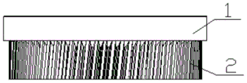
FIG. 1 is a front view of a gear structure with an oil-proof ring according to an embodiment of the present invention;
FIG. 2 is a top view of a gear structure with an oil seal according to an embodiment of the present invention;
FIG. 3 is a schematic cross-sectional view of a gear structure with an oil-proof ring according to an embodiment of the present invention;
fig. 4 is a bottom view of a gear structure with an oil-proof ring in one embodiment of the invention.
Detailed Description
As shown in fig. 1 to 4, the invention provides a gear structure with an oil-proof ring, the gear structure with the oil-proof ring comprises a gear portion 2 and a cylindrical oil-proof ring 1, a central axis of the oil-proof ring 1 and a central axis of the gear portion 2 are on the same straight line, the oil-proof ring 1 is connected with the gear portion 2, the gear structure with the oil-proof ring is vertically placed, the bottom of the oil-proof ring 1 is connected with the top of the gear portion 2, the oil-proof ring 1 and the gear portion 2 are vertically projected, the projection of the oil-proof ring 1 covers the projection of the gear portion 2, the gear portion 2 forms a projection a on the oil-proof ring 1 by using a vertical projection technology, a part of the outer side of the oil-proof ring 1, which exceeds the projection a, is a retaining ring, and a reserved connecting hole is arranged in the middle position of the gear structure with the oil-proof ring. Through the effectual grease that has avoided of the design of oil drain ring 1 to splash to the drive ring, the position that need not use the grease such as transmission buckle groove causes side effects such as skidding, the effectual product of using the gear of overcoming is because the function failure that the grease skids and causes in the use, the effectual reliability of having guaranteed in the use, by a wide margin the life of product, simultaneously through the effectual grease that will run off of retaining ring reflux to the meshing position, can effectively prevent the grease loss, the utilization ratio of grease has been increased simultaneously, the effectual lubricity that has promoted gear part, the life of gear part has been promoted, the comfort level that the improvement customer used.
As the optimization of this embodiment, oil ring 1 and gear portion 2 integrated casting shaping, the effectual joint strength who promotes between oil ring 1 and the gear portion 2 has guaranteed the life of taking the gear structure of oil ring certainly.
As a preferred embodiment, as shown in fig. 3 and 4, the bottom of the gear part 2 is provided with a circular groove, a reinforcing rib 9 is arranged in the groove, the top of the reinforcing rib 9 is connected with the bottom of the gear part 2, the reinforcing rib 9 includes eight strip-shaped first reinforcing ribs which are circumferentially and uniformly distributed by using the reserved connecting hole as a center, an arc-shaped second reinforcing rib is arranged between two adjacent first reinforcing ribs, eight second reinforcing ribs are arranged on the same circle a, and the circle a and the groove are in a concentric circle structure at the same height horizontal section. Therefore, the stability of the structure of the gear part 2 can be better improved, and the service life of the gear part 2 is further ensured.
As a preferred embodiment, as shown in fig. 2 and 3, a cylindrical first through hole 4 and a cylindrical first groove 5 are provided in the middle of the gear portion 2, the first groove 5 is communicated with the first through hole 4, a second groove 7 is provided outside the first groove 5, an annular transmission coil 3 is provided between the first groove 5 and the second groove 7, six transmission coil fastening grooves 6 are uniformly and annularly provided on the transmission coil 3, a cylindrical second through hole 8 is provided in the middle of the oil-proof ring 1, the first groove 5 and the second groove 7 are both communicated with the second through hole 8, the first through hole 4, the first groove 5, the second groove 7 and the second through hole 8 are connected to form a reserved connection hole, and the inner side and the outer side of the transmission coil fastening groove 6 are respectively communicated with the first groove 5 and the second groove 7.
The foregoing is only a preferred form of the invention and it should be noted that several similar variations and modifications could be made by one skilled in the art without departing from the inventive concept and these should also be considered within the scope of the invention.
Claims (7)
1. A gear structure with an oil-proof ring is characterized by comprising a gear part (2) and a cylindrical oil-proof ring (1), wherein the central shaft of the oil-proof ring (1) and the central shaft of the gear part (2) are on the same straight line, the oil-proof ring (1) is connected with the gear part (2), the gear structure with the oil-proof ring is vertically placed, the bottom of the oil-proof ring (1) is connected with the top of the gear part (2), the oil-proof ring (1) and the gear part (2) are vertically projected, the projection of the oil-proof ring (1) covers the projection of the gear part (2), a reserved connecting hole is arranged at the middle position of the gear structure with the oil-proof ring, a first through hole (4) and a first groove (5) are arranged at the middle position of the gear part (2), the first groove (5) is communicated with the first through hole (4), a second groove (7) is arranged at the outer side of the first groove (5), be equipped with between first recess (5) and second recess (7) drive ring (3), evenly be equipped with three drive ring buckle groove (6) at least on drive ring (3), the intermediate position of oil ring (1) is equipped with second through-hole (8), and first recess (5) and second recess (7) all communicate with second through-hole (8), and first through-hole (4), first recess (5), second recess (7) and second through-hole (8) are connected and are formed and reserve the connecting hole.
2. The gear structure with the oil-proof ring is characterized in that the oil-proof ring (1) is integrally cast and formed with the gear part (2) according to the claim 1.
3. The gear structure with the oil-proof ring is characterized in that the gear part (2) forms a projection A on the oil-proof ring (1) by utilizing a vertical projection technology, and the part of the outer side edge of the oil-proof ring (1) beyond the projection A is a retaining ring.
4. The gear structure with the oil-proof ring is characterized in that a circular groove is formed in the bottom of the gear portion (2), reinforcing ribs (9) are arranged in the groove, the tops of the reinforcing ribs (9) are connected with the bottom of the gear portion (2), the reinforcing ribs (9) comprise eight strip-shaped first reinforcing ribs which are circumferentially and uniformly distributed by taking the reserved connecting hole as a center, and an arc-shaped second reinforcing rib is arranged between every two adjacent first reinforcing ribs, so that eight second reinforcing ribs are arranged.
5. The gear structure with the oil-proof ring as claimed in claim 4, wherein eight second reinforcing ribs are arranged on the same circle A, and the horizontal section of the circle A and the horizontal section of the groove at the same height are in a concentric circle structure.
6. The gear structure with the oil-proof ring is characterized in that the first through hole (4) is cylindrical, the first groove (5) is cylindrical, the second groove (7) is annular, the transmission ring (3) is annular, six transmission ring buckling grooves (6) are uniformly and annularly arranged on the transmission ring (3), and the second through hole (8) is cylindrical.
7. The gear structure with the oil-proof ring is characterized in that the inner side and the outer side of the transmission ring buckling groove (6) are respectively communicated with the first groove (5) and the second groove (7).
Priority Applications (1)
| Application Number | Priority Date | Filing Date | Title |
|---|---|---|---|
| CN201910067621.4A CN109578552B (en) | 2019-01-24 | 2019-01-24 | From gear structure of taking oil ring |
Applications Claiming Priority (1)
| Application Number | Priority Date | Filing Date | Title |
|---|---|---|---|
| CN201910067621.4A CN109578552B (en) | 2019-01-24 | 2019-01-24 | From gear structure of taking oil ring |
Publications (2)
| Publication Number | Publication Date |
|---|---|
| CN109578552A CN109578552A (en) | 2019-04-05 |
| CN109578552B true CN109578552B (en) | 2022-02-01 |
Family
ID=65917349
Family Applications (1)
| Application Number | Title | Priority Date | Filing Date |
|---|---|---|---|
| CN201910067621.4A Active CN109578552B (en) | 2019-01-24 | 2019-01-24 | From gear structure of taking oil ring |
Country Status (1)
| Country | Link |
|---|---|
| CN (1) | CN109578552B (en) |
Families Citing this family (1)
| Publication number | Priority date | Publication date | Assignee | Title |
|---|---|---|---|---|
| CN116697024A (en) * | 2022-02-28 | 2023-09-05 | 日本电产(大连)有限公司 | Gear box and gear motor |
Citations (7)
| Publication number | Priority date | Publication date | Assignee | Title |
|---|---|---|---|---|
| US4643040A (en) * | 1984-08-08 | 1987-02-17 | Siemens Aktiengesellschaft | Worm gear train arrangement and housing |
| CN101115938A (en) * | 2005-01-19 | 2008-01-30 | 株式会社美姿把 | Rolling Dies for Gears and Gear Forming |
| CN101384412A (en) * | 2006-02-21 | 2009-03-11 | 博格华纳公司 | Integrated shaft, gear and rotor |
| CN104373559A (en) * | 2014-08-22 | 2015-02-25 | 洛阳轴研科技股份有限公司 | Two-shaft assembly used in speed changer of loader |
| CN105545927A (en) * | 2015-11-27 | 2016-05-04 | 沪东重机有限公司 | Diesel engine crankshaft gear connection structure convenient to replace after failure |
| CN207064605U (en) * | 2017-07-08 | 2018-03-02 | 余姚市宇洲电器有限公司 | A kind of wiper gear |
| CN108953560A (en) * | 2018-08-02 | 2018-12-07 | 泰州里华齿轮制造有限公司 | A kind of stable washer of adjustable gear of special reinforcement type |
Family Cites Families (5)
| Publication number | Priority date | Publication date | Assignee | Title |
|---|---|---|---|---|
| AT506562B1 (en) * | 2007-04-30 | 2011-05-15 | Miba Sinter Austria Gmbh | PULLEY |
| CN201973205U (en) * | 2011-03-22 | 2011-09-14 | 浙江吉隆机械有限公司 | Pinion |
| CN203703058U (en) * | 2014-01-28 | 2014-07-09 | 东莞市洁澳思五金制品有限公司 | A Zinc Alloy Die Casting Spur Gear |
| CN207161669U (en) * | 2017-08-08 | 2018-03-30 | 泰兴市金城纺机齿轮制造有限公司 | A kind of large-scale frame wear-resistant gear |
| CN107606107A (en) * | 2017-09-07 | 2018-01-19 | 泰州市瑞洋汽车配件厂 | A kind of special multiaxis assembling gear part |
-
2019
- 2019-01-24 CN CN201910067621.4A patent/CN109578552B/en active Active
Patent Citations (7)
| Publication number | Priority date | Publication date | Assignee | Title |
|---|---|---|---|---|
| US4643040A (en) * | 1984-08-08 | 1987-02-17 | Siemens Aktiengesellschaft | Worm gear train arrangement and housing |
| CN101115938A (en) * | 2005-01-19 | 2008-01-30 | 株式会社美姿把 | Rolling Dies for Gears and Gear Forming |
| CN101384412A (en) * | 2006-02-21 | 2009-03-11 | 博格华纳公司 | Integrated shaft, gear and rotor |
| CN104373559A (en) * | 2014-08-22 | 2015-02-25 | 洛阳轴研科技股份有限公司 | Two-shaft assembly used in speed changer of loader |
| CN105545927A (en) * | 2015-11-27 | 2016-05-04 | 沪东重机有限公司 | Diesel engine crankshaft gear connection structure convenient to replace after failure |
| CN207064605U (en) * | 2017-07-08 | 2018-03-02 | 余姚市宇洲电器有限公司 | A kind of wiper gear |
| CN108953560A (en) * | 2018-08-02 | 2018-12-07 | 泰州里华齿轮制造有限公司 | A kind of stable washer of adjustable gear of special reinforcement type |
Also Published As
| Publication number | Publication date |
|---|---|
| CN109578552A (en) | 2019-04-05 |
Similar Documents
| Publication | Publication Date | Title |
|---|---|---|
| KR101179656B1 (en) | Lubricating pinion, lubricating device, gearbox and method for manufacturing lubricating pinion | |
| US9506550B2 (en) | Gear for a spur gear stage without play | |
| CN109578552B (en) | From gear structure of taking oil ring | |
| US10151382B2 (en) | Planetary gear carrier assembly and related method of making | |
| US9568088B2 (en) | Plug for a planetary pin assembly | |
| US8783996B2 (en) | Insert ring for spline coupling | |
| CN202612582U (en) | Lubrication structure of transmission gear | |
| JP6903757B2 (en) | Rolling boots with at least one reinforcing fin | |
| CN110296204B (en) | Shaft sealing structure and integrated driving system | |
| CN107757259B (en) | Non-inflatable tyre | |
| CN209725152U (en) | A kind of transmission combination gear | |
| CN205401641U (en) | Tooth wheel hub | |
| CN210034351U (en) | Input shaft structure of two-gear electric transmission | |
| CN207297675U (en) | The drag ring of synchronizer | |
| CN117267360A (en) | Multi-point forced lubrication system of box-type transmission and box-type transmission | |
| CN205423597U (en) | Automobile synchronizer | |
| JP5120591B2 (en) | Thrust bearing | |
| CN219413230U (en) | Anti-rust guide wheel shaft | |
| KR100243592B1 (en) | Automotive Bush | |
| CN222526844U (en) | Spline lubricating structure, escalator and personnel transportation device | |
| CN205588915U (en) | A connect bearing for bumper shock absorber | |
| CN216279271U (en) | Self-lubricating gearbox gear | |
| US2142632A (en) | End closure for axle housings | |
| CN219432386U (en) | Integrated transmission intermediate shaft | |
| CN217874167U (en) | Shaft seat sealing structure of cold header |
Legal Events
| Date | Code | Title | Description |
|---|---|---|---|
| PB01 | Publication | ||
| PB01 | Publication | ||
| SE01 | Entry into force of request for substantive examination | ||
| SE01 | Entry into force of request for substantive examination | ||
| GR01 | Patent grant | ||
| GR01 | Patent grant |