CN109489623B - Method for measuring uneven settlement of approach at bridge head by adopting three-dimensional laser scanner - Google Patents
Method for measuring uneven settlement of approach at bridge head by adopting three-dimensional laser scanner Download PDFInfo
- Publication number
- CN109489623B CN109489623B CN201811411269.3A CN201811411269A CN109489623B CN 109489623 B CN109489623 B CN 109489623B CN 201811411269 A CN201811411269 A CN 201811411269A CN 109489623 B CN109489623 B CN 109489623B
- Authority
- CN
- China
- Prior art keywords
- point cloud
- cloud data
- road
- registration
- elevation
- Prior art date
- Legal status (The legal status is an assumption and is not a legal conclusion. Google has not performed a legal analysis and makes no representation as to the accuracy of the status listed.)
- Active
Links
- 238000000034 method Methods 0.000 title claims abstract description 37
- 238000013459 approach Methods 0.000 title claims abstract description 22
- 238000001514 detection method Methods 0.000 claims abstract description 26
- 238000013519 translation Methods 0.000 claims description 9
- 239000003550 marker Substances 0.000 claims description 6
- 241000287196 Asthenes Species 0.000 claims description 3
- 239000003086 colorant Substances 0.000 claims description 3
- 238000007781 pre-processing Methods 0.000 claims description 3
- 238000005259 measurement Methods 0.000 abstract description 8
- 238000010586 diagram Methods 0.000 description 3
- 238000012544 monitoring process Methods 0.000 description 3
- 238000003384 imaging method Methods 0.000 description 2
- 230000009286 beneficial effect Effects 0.000 description 1
- 230000007547 defect Effects 0.000 description 1
- 238000012545 processing Methods 0.000 description 1
- 230000003068 static effect Effects 0.000 description 1
- 239000000126 substance Substances 0.000 description 1
- 239000002023 wood Substances 0.000 description 1
Images


Classifications
-
- G—PHYSICS
- G01—MEASURING; TESTING
- G01C—MEASURING DISTANCES, LEVELS OR BEARINGS; SURVEYING; NAVIGATION; GYROSCOPIC INSTRUMENTS; PHOTOGRAMMETRY OR VIDEOGRAMMETRY
- G01C5/00—Measuring height; Measuring distances transverse to line of sight; Levelling between separated points; Surveyors' levels
Abstract
The invention discloses a method for measuring uneven settlement of a bridge head approach by adopting a three-dimensional laser scanner, which comprises the following steps: carrying a three-dimensional laser scanner on a road to be detected by utilizing a moving carrier to perform walking and stopping scanning, and acquiring multi-station and multi-period point cloud data of the road to be detected; respectively carrying out plane registration and elevation registration on multi-station and multi-stage point cloud data by using the traffic markers; and uniformly selecting a plurality of deformation detection points with the same plane position in the point cloud data of each period after registration, and respectively calculating and comparing the elevation data of the deformation detection points in the point cloud data of different periods according to the plane positions of the deformation detection points so as to obtain the differential settlement information of the road to be detected. The invention has the advantages that: the movable carrier is used for carrying the three-dimensional laser scanner to scan, so that the uneven settlement information of the bridge head approach can be rapidly, comprehensively and accurately acquired, meanwhile, the operator can carry out measurement operation on the movable carrier, and the safety coefficient of measurement is effectively improved.
Description
Technical Field
The invention relates to the field of three-dimensional laser imaging and measurement, in particular to a method for measuring uneven settlement of a bridge head approach by adopting a three-dimensional laser scanner.
Background
The bridge approach of the highway is easy to have uneven settlement in the use process, and the vehicle can jump when passing through the approach at high speed, thereby seriously affecting the driving safety. Therefore, the settlement monitoring is required to be carried out at the bridge head approach of the highway regularly.
At present, a precise leveling method is adopted for monitoring the bridge head approach settlement, the precision of the traditional leveling method is high, but operation personnel need to perform operations such as station erecting, ruler supporting, measurement and the like on an emergency lane, the danger coefficient is high, and the personal safety of the operation personnel cannot be guaranteed.
The three-dimensional laser scanning technology is a non-contact measuring method and has the advantages of high measuring speed, high measuring precision and the like, so the three-dimensional laser scanning technology has obvious technical advantages in settlement monitoring of bridge head approach.
Disclosure of Invention
The invention aims to provide a method for measuring uneven settlement of a bridge head approach by adopting a three-dimensional laser scanner according to the defects of the prior art, wherein the method comprises the steps of carrying the three-dimensional laser scanner by a motion carrier, and scanning the three-dimensional laser scanner on a road to be detected in a walking and stopping manner to obtain point cloud data of the road to be detected in multiple stations and multiple periods; respectively carrying out plane registration and elevation registration on multi-station and multi-stage point cloud data by using traffic sign lines; and uniformly selecting a plurality of deformation detection points with the same plane position in the point cloud data of each period after registration, and respectively calculating and comparing the elevation data of the deformation detection points in the point cloud data of different periods according to the plane positions of the deformation detection points so as to obtain the differential settlement information of the road to be detected.
The purpose of the invention is realized by the following technical scheme:
a method for measuring uneven settlement of a bridge head approach by adopting a three-dimensional laser scanner is characterized by comprising the following steps: stopping the moving carrier loaded with the three-dimensional laser scanner once at intervals in the process of advancing on a road to be detected, and scanning the road to be detected by using the three-dimensional laser scanner during each stationary period to acquire point cloud data of the road of the station including a traffic marker until the multi-station scanning of the road to be detected is completed; repeating the steps at intervals to realize the multi-period scanning of the road to be detected; respectively carrying out plane registration and elevation registration on multi-station point cloud data and multi-stage point cloud data in each stage by using the traffic marker; and uniformly selecting a plurality of deformation detection points with the same plane position in the point cloud data of each period after registration, and respectively calculating and comparing the elevation data of the deformation detection points in the point cloud data of different periods according to the plane positions of the deformation detection points so as to obtain the differential settlement information of the road to be detected.
And preprocessing the acquired point cloud data such as denoising, compressing and the like before the multi-station and multi-period point cloud data registration.
The method further comprises the steps of: and performing three-dimensional display on the uneven settlement of the road to be detected by adopting different colors to generate an uneven settlement three-dimensional deviation chromatogram of the road to be detected.
The method for performing plane registration and elevation registration on multi-station point cloud data and multi-stage point cloud data in each stage by using the traffic marker comprises the following steps: generating a gray image of the road to be detected by using the intensity information of the point cloud data; identifying the traffic sign in the gray image by adopting an image identification technology; extracting the traffic signs in the point cloud data of two adjacent stations and two adjacent stages, and performing plane registration and elevation registration on the point cloud data of the two adjacent stations and the two adjacent stages; and repeating the steps to complete the registration of the point cloud data of multiple stations and phases in each phase.
When the traffic sign is a rectangular traffic sign line, the specific process of performing plane registration on the point cloud data of two adjacent stations and two adjacent periods comprises the following steps:
(1) extracting four corner points of the rectangular traffic sign line in the point cloud data Plane coordinates of (2):
 ;
;
(2) calculating the rotation angle of the two adjacent stations/two adjacent phases of plane coordinate transformation The calculation formula is as follows:
 ,
, ,
, wherein, in the step (A),
 the slopes of the two long sides of the rectangular traffic sign line in the previous station/period,
 slopes of two long sides of the rectangular traffic sign line in a latter station/phase;
(3) calculating plane coordinate translation parameters of two adjacent stations/two adjacent phases :
:


(4) Performing plane registration on the point cloud data of two adjacent stations/two adjacent periods: the plane coordinate before the point cloud data of the next station/the next period is registered as Then the registered plane coordinates are:

the specific process of performing elevation registration on the point cloud data of two adjacent stations comprises the following steps:
selecting a public point cloud set with the radius of 2cm in the point cloud data of two adjacent stations, wherein the public point cloud set is positioned in the middle area of the road to be detected Separately computing a set of point clouds
 Is recorded as
 And then the elevation translation parameters of two adjacent stations
 (ii) a The elevation coordinate before the point cloud data of the next station are registered is set as
 And then the registered elevation coordinates are:
 。
。
the specific process for performing elevation registration on the point cloud data of two adjacent periods comprises the following steps:
selecting a common point cloud set with the radius of 2cm in an elevation reference area with a stable foundation of the road to be detected from the point cloud data of two adjacent periods Separately computing a set of point clouds
 Is recorded as
 And then the elevation translation parameters of two adjacent stations
 (ii) a The elevation coordinate before the point cloud data of the later period is registered as
 And then the registered elevation coordinates are:
 。
。
the invention has the advantages that: (1) the uneven settlement information of the bridge head approach can be rapidly, comprehensively and accurately obtained by utilizing the moving carrier to carry the three-dimensional laser scanner for scanning; (2) the operation personnel can carry out the measurement operation on the motion carrier, have effectively improved the factor of safety of measurement.
Drawings
FIG. 1 is a schematic view of a process for measuring differential settlement of a bridge approach by using a three-dimensional laser scanner according to the present invention;
FIG. 2 is a schematic structural diagram of a three-dimensional laser scanner carried by a moving carrier according to the present invention;
FIG. 3 is a schematic view of a traffic sign line of a road to be detected in the present invention;
FIG. 4 is a schematic diagram of registered point cloud data in accordance with the present invention;
FIG. 5 is a schematic diagram of the distribution of deformation detection points according to the present invention;
FIG. 6 is a three-dimensional deviation chromatogram of the differential settlement of the road to be detected in the invention;
fig. 7 is an enlarged view of a portion a of fig. 6.
Detailed Description
The features of the present invention and other related features are described in further detail below by way of example in conjunction with the following drawings to facilitate understanding by those skilled in the art:
referring to fig. 1-7, the labels 1-4 in the figures are: the device comprises a motion carrier 1, a three-dimensional laser scanner 2, a traffic sign line 3 and a deformation detection point 4.
Example (b): as shown in fig. 1-7, the embodiment specifically relates to a method for measuring uneven settlement of a bridge approach by using a three-dimensional laser scanner, in which a moving carrier 1 is used to carry a three-dimensional laser scanner 2 to scan and stop on a road to be detected to obtain point cloud data of the road to be detected in multiple stations and multiple periods; carrying out plane registration and elevation registration on multi-station and multi-stage point cloud data by using the traffic sign line 3; and uniformly selecting a plurality of deformation detection points 4 with the same plane position in the point cloud data of each period after registration, and respectively calculating and comparing the elevation data of the deformation detection points 4 in the point cloud data of different periods according to the plane positions of the deformation detection points 4, thereby obtaining the differential settlement information of the road to be detected.
As shown in fig. 1 to 7, the method for measuring uneven settlement of a bridge approach by using a three-dimensional laser scanner in the embodiment includes the following steps:
(1) processing and integrating a set of motion carrier 1, carrying a three-dimensional laser scanner 2 by using the motion carrier 1 and moving forward on a road to be detected, enabling a detection person to perform walking and stopping scanning on the motion carrier 1 through the three-dimensional laser scanner 2, namely controlling the motion carrier 1 to stop moving once at a certain distance, scanning point cloud data of the station for acquiring the road to be detected by using the three-dimensional laser scanner 2 during a static period, ensuring that a traffic sign line 3 on the road to be detected is completely scanned and acquired in a scanning process, and repeating the steps until multi-station scanning of the road to be detected is completed; as shown in fig. 2, the moving carrier 1 in this embodiment is a measuring vehicle with a skylight, a measuring platform is installed at the top of the measuring vehicle, and a three-dimensional gazing scanner 2 and a leveling device are installed on the platform, so that leveling, scanning and other operations of measuring personnel are facilitated; the traffic sign line 3 in this embodiment is rectangular as shown in fig. 3, and certainly, traffic signs in other shapes such as circles can be selected, and the traffic sign line 3 is used as a mark with obvious and same characteristics in cloud data of each point and can be used for registration among the cloud data of each point;
(2) repeating the step (1) at intervals of time, such as one week or one month, and carrying out scanning by using the three-dimensional laser scanner 2 carried by the motion carrier 1 to obtain multi-phase point cloud data of the road to be detected;
(3) preprocessing multi-station and multi-period point cloud data such as denoising and compressing;
(4) the method comprises the following steps of respectively carrying out plane registration and elevation registration on multi-station point cloud data and multi-period point cloud data in each period by using a traffic sign line 3, wherein the specific process comprises the following steps: generating a gray image of the road to be detected at each station and each period by using the intensity information of the point cloud data; identifying the traffic sign line in the gray image by adopting an image identification technology; extracting parameters of traffic signs in the point cloud data of two adjacent stations and two adjacent stages, and performing plane registration and elevation registration on the point cloud data of the two adjacent stations and the two adjacent stages; repeating the steps to complete the registration of the point cloud data of multiple stations and multiple periods in each period; wherein the content of the first and second substances,
(4.1) when the traffic sign is a rectangular traffic sign line 3, the specific process of carrying out plane registration on the point cloud data of two adjacent stations and two adjacent periods comprises the following steps:
(a) extracting four corner points of traffic sign line 3 in point cloud data Plane coordinates of (2):
 ;
;
(b) calculating the rotation angle of the two adjacent stations/two adjacent phases of plane coordinate transformation The calculation formula is as follows:
 ,
, ,
, wherein, in the step (A),
 the slopes of the two long sides of the
 traffic sign line 3 in the previous station/period, the slopes of the two long sides of the
 traffic sign line 3 in the latter station/phase;
(c) calculating plane coordinate translation parameters of two adjacent stations/two adjacent phases The calculation formula is as follows:

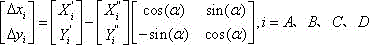
(d) performing plane registration on the point cloud data of two adjacent stations/two adjacent periods: the plane coordinate before the point cloud data of the next station/the next period is registered as Then the registered plane coordinates are:

(4.2) the specific process of performing elevation registration on the point cloud data of two adjacent stations comprises the following steps:
(a) selecting a public point cloud set with the radius of 2cm in the point cloud data of two adjacent stations, wherein the public point cloud set is positioned in the middle area of the road to be detected Separately computing a set of point clouds
 Is recorded as
 ;
;
(b) The elevation translation parameters of two adjacent stations ;
;
(c) The elevation coordinate before the point cloud data of the next station are registered is set as And then the registered elevation coordinates are:
 ;
;
(4.3) the specific process of performing elevation registration on the point cloud data of two adjacent periods comprises the following steps:
(a) selecting a common point cloud set with the radius of 2cm in an elevation reference area with a stable foundation of the road to be detected from the point cloud data of two adjacent periods Separately computing a set of point clouds
 Is recorded as
 ;
;
(b) The elevation translation parameters of two adjacent stations ;
;
(c) The elevation coordinate before the point cloud data of the later period is registered as And then the registered elevation coordinates are:
 ;
;
the imaging of the multi-station point cloud data after the registration is completed through the steps is shown in FIG. 4;
(5) uniformly selecting a plurality of deformation detection points 4 with the same plane position in the point cloud data of each period after registration, uniformly distributing the deformation detection points 4 on a road to be detected, wherein the distance between the deformation detection points 4 is not more than 1m, the number of the deformation detection points is determined according to the length and the width of the road to be detected, then respectively calculating the elevation data of the plurality of deformation detection points 4 selected in the point cloud data of each period according to the plane position of the deformation detection points, comparing the change condition of the elevation data between different periods, and analyzing the uneven settlement information of the road to be detected; as shown in fig. 5, in this embodiment, four rows of deformation detection points are selected on the road image to be detected, and each row has a plurality of deformation detection points arranged along the extending direction of the road to be detected;
(6) three-dimensionally displaying the uneven settlement of the road to be detected by adopting different colors to generate an uneven settlement three-dimensional deviation chromatogram of the road to be detected, as shown in FIG. 6; wherein, a wood board is artificially added on the road to be detected between two scanning stages to form a road surface 'bulge', namely a part indicated by A in figure 6, and the enlarged view is shown in figure 7; the uneven settlement condition of the road to be detected can be visually and clearly seen from fig. 6 and 7; of course, a report can be automatically generated, and the uneven settlement condition can be directly and accurately reflected in a data form.
The beneficial effect of this embodiment is: (1) the uneven settlement information of the bridge head approach can be rapidly, comprehensively and accurately obtained by utilizing the moving carrier to carry the three-dimensional laser scanner for scanning; (2) the operation personnel can carry out the measurement operation on the motion carrier, have effectively improved the factor of safety of measurement.
Claims (5)
1. A method for measuring uneven settlement of a bridge head approach by adopting a three-dimensional laser scanner is characterized by comprising the following steps: stopping the moving carrier loaded with the three-dimensional laser scanner once at intervals in the process of advancing on a road to be detected, and scanning the road to be detected by using the three-dimensional laser scanner during each stationary period to acquire point cloud data of the road of the station including a traffic marker until the multi-station scanning of the road to be detected is completed; repeating the steps at intervals to realize the multi-period scanning of the road to be detected; respectively carrying out plane registration and elevation registration on multi-station point cloud data and multi-stage point cloud data in each stage by using the traffic marker; uniformly selecting a plurality of deformation detection points with the same plane position in the point cloud data of each period after registration, and respectively calculating and comparing the elevation data of the deformation detection points in the point cloud data of different periods according to the plane positions of the deformation detection points so as to obtain the differential settlement information of the road to be detected;
the method for performing plane registration and elevation registration on multi-station point cloud data and multi-stage point cloud data in each stage by using the traffic marker comprises the following steps: generating a gray image of the road to be detected by using the intensity information of the point cloud data; identifying the traffic sign in the gray image by adopting an image identification technology; extracting the traffic signs in the point cloud data of two adjacent stations and two adjacent stages, and performing plane registration and elevation registration on the point cloud data of the two adjacent stations and the two adjacent stages; repeating the steps to complete the registration of the point cloud data of multiple stations and multiple periods in each period; when the traffic sign is a rectangular traffic sign line, the specific process of performing plane registration on the point cloud data of two adjacent stations and two adjacent periods comprises the following steps:
(1) extracting four corner points of the rectangular traffic sign line in the point cloud data Plane coordinates of (2):
 ;
;
(2) calculating the rotation angle of the two adjacent stations/two adjacent phases of plane coordinate transformation The calculation formula is as follows:
 ,
, ,
, wherein, in the step (A),
 the slopes of the two long sides of the rectangular traffic sign line in the previous station/period,
 slopes of two long sides of the rectangular traffic sign line in a latter station/phase;
(3) calculating plane coordinate translation parameters of two adjacent stations/two adjacent phases :
:


(4) Performing plane registration on the point cloud data of two adjacent stations/two adjacent periods: the plane coordinate before the point cloud data of the next station/the next period is registered as Then the registered plane coordinates are:

2. the method for measuring bridge approach differential settlement by using the three-dimensional laser scanner as claimed in claim 1, wherein the obtained point cloud data is subjected to denoising and compressing preprocessing before the multi-station and multi-period point cloud data is registered.
3. The method for measuring bridge approach differential settlement using three-dimensional laser scanner as claimed in claim 1, characterized in that the method further comprises the steps of: and performing three-dimensional display on the uneven settlement of the road to be detected by adopting different colors to generate an uneven settlement three-dimensional deviation chromatogram of the road to be detected.
4. The method for measuring uneven settlement of the approach of the bridge head by using the three-dimensional laser scanner as claimed in claim 1, wherein the specific process of performing elevation registration on the point cloud data of two adjacent stations comprises the following steps:
selecting a public point cloud set with the radius of 2cm in the point cloud data of two adjacent stations, wherein the public point cloud set is positioned in the middle area of the road to be detected Separately computing a set of point clouds
 Is recorded as
 And then the elevation translation parameters of two adjacent stations
 (ii) a The elevation coordinate before the point cloud data of the next station are registered is set as
 And then the registered elevation coordinates are:
 。
。
5. the method for measuring uneven settlement of the approach of the bridge head by using the three-dimensional laser scanner as claimed in claim 1, wherein the specific process of performing elevation registration on the point cloud data of two adjacent stages comprises the following steps:
selecting a common point cloud set with the radius of 2cm in an elevation reference area with a stable foundation of the road to be detected from the point cloud data of two adjacent periods Separately computing a set of point clouds
 Is recorded as
 And then the elevation translation parameters of two adjacent stations
 (ii) a The elevation coordinate before the point cloud data of the later period is registered as
 And then the registered elevation coordinates are:
 。
。
Priority Applications (1)
| Application Number | Priority Date | Filing Date | Title |
|---|---|---|---|
| CN201811411269.3A CN109489623B (en) | 2018-11-24 | 2018-11-24 | Method for measuring uneven settlement of approach at bridge head by adopting three-dimensional laser scanner |
Applications Claiming Priority (1)
| Application Number | Priority Date | Filing Date | Title |
|---|---|---|---|
| CN201811411269.3A CN109489623B (en) | 2018-11-24 | 2018-11-24 | Method for measuring uneven settlement of approach at bridge head by adopting three-dimensional laser scanner |
Publications (2)
| Publication Number | Publication Date |
|---|---|
| CN109489623A CN109489623A (en) | 2019-03-19 |
| CN109489623B true CN109489623B (en) | 2021-05-11 |
Family
ID=65697785
Family Applications (1)
| Application Number | Title | Priority Date | Filing Date |
|---|---|---|---|
| CN201811411269.3A Active CN109489623B (en) | 2018-11-24 | 2018-11-24 | Method for measuring uneven settlement of approach at bridge head by adopting three-dimensional laser scanner |
Country Status (1)
| Country | Link |
|---|---|
| CN (1) | CN109489623B (en) |
Families Citing this family (4)
| Publication number | Priority date | Publication date | Assignee | Title |
|---|---|---|---|---|
| CN110670461A (en) * | 2019-11-14 | 2020-01-10 | 上海宝冶建筑工程有限公司 | Method for detecting flatness of airport pavement |
| CN113326554A (en) * | 2020-11-18 | 2021-08-31 | 上海慕荣电气有限公司 | Point cloud data-based observation method for settlement evolution process of foundation of transformer substation equipment |
| CN112381944B (en) * | 2020-11-18 | 2023-03-28 | 同济大学 | Point cloud data-based 4D observation method for transmission line tower deformation |
| CN113808124A (en) * | 2021-09-27 | 2021-12-17 | 河南中检工程检测有限公司 | Bridgehead bump judgment method based on point cloud technology |
Citations (6)
| Publication number | Priority date | Publication date | Assignee | Title |
|---|---|---|---|---|
| CN102607512A (en) * | 2011-01-25 | 2012-07-25 | 吴立新 | Vehicle-mounted laser measuring method for mining area subsidence |
| JP2015052205A (en) * | 2013-09-05 | 2015-03-19 | 鹿島建設株式会社 | Compaction management method and compaction management system |
| CN104533520A (en) * | 2014-12-01 | 2015-04-22 | 长沙理工大学 | Tunnel arch crown settlement and peripheral convergence monitoring method |
| CN106597470A (en) * | 2016-12-22 | 2017-04-26 | 中国矿业大学 | Three-dimensional point cloud data acquisition device and three-dimensional point cloud data acquisition method by means of two-dimensional laser scanner |
| CN106840088A (en) * | 2017-02-27 | 2017-06-13 | 武汉理工大学 | A kind of onboard combined navigation roadbed subsidence method for fast measuring |
| CN107063179A (en) * | 2017-04-27 | 2017-08-18 | 上海同岩土木工程科技股份有限公司 | A kind of movable tunnel cross section deformation detection means |
-
2018
- 2018-11-24 CN CN201811411269.3A patent/CN109489623B/en active Active
Patent Citations (6)
| Publication number | Priority date | Publication date | Assignee | Title |
|---|---|---|---|---|
| CN102607512A (en) * | 2011-01-25 | 2012-07-25 | 吴立新 | Vehicle-mounted laser measuring method for mining area subsidence |
| JP2015052205A (en) * | 2013-09-05 | 2015-03-19 | 鹿島建設株式会社 | Compaction management method and compaction management system |
| CN104533520A (en) * | 2014-12-01 | 2015-04-22 | 长沙理工大学 | Tunnel arch crown settlement and peripheral convergence monitoring method |
| CN106597470A (en) * | 2016-12-22 | 2017-04-26 | 中国矿业大学 | Three-dimensional point cloud data acquisition device and three-dimensional point cloud data acquisition method by means of two-dimensional laser scanner |
| CN106840088A (en) * | 2017-02-27 | 2017-06-13 | 武汉理工大学 | A kind of onboard combined navigation roadbed subsidence method for fast measuring |
| CN107063179A (en) * | 2017-04-27 | 2017-08-18 | 上海同岩土木工程科技股份有限公司 | A kind of movable tunnel cross section deformation detection means |
Also Published As
| Publication number | Publication date |
|---|---|
| CN109489623A (en) | 2019-03-19 |
Similar Documents
| Publication | Publication Date | Title |
|---|---|---|
| CN109489623B (en) | Method for measuring uneven settlement of approach at bridge head by adopting three-dimensional laser scanner | |
| US10755132B2 (en) | Methods for extracting surface deformation feature of object based on linear scanning three-dimensional point cloud | |
| CN106093963A (en) | A kind of method improving railway vehicle-mounted Laser Radar Scanning data precision | |
| CN107239780A (en) | A kind of image matching method of multiple features fusion | |
| Cabo et al. | An algorithm for automatic road asphalt edge delineation from mobile laser scanner data using the line clouds concept | |
| CN103954458B (en) | Non-contacting type four-wheel aligner and detecting method thereof | |
| CN109544607B (en) | Point cloud data registration method based on road sign line | |
| CN103927748B (en) | A kind of coordinate scaling method based on many rectangular images distance transformation model | |
| CN203824548U (en) | Bridge structure concrete surface observation area measuring instrument | |
| CN107664492A (en) | The deflection angle measuring method and system of harbour gantry crane laser scanner installation | |
| CN105891220A (en) | Pavement marker line defect detecting device and detecting method thereof | |
| CN112785654A (en) | Calibration method and device for track geometry detection system | |
| CN102446355A (en) | Method for detecting target protruding from plane based on double viewing fields without calibration | |
| CN110660094A (en) | Subway tunnel mobile scanning point cloud fine division method based on image recognition | |
| Umehara et al. | Research on identification of road features from point cloud data using deep learning | |
| CN102306382A (en) | Image correcting method of accident scene based on inherent characteristics of road environment | |
| JP5274173B2 (en) | Vehicle inspection device | |
| Jaselskis et al. | Pilot study on laser scanning technology for transportation projects | |
| Ji et al. | Accurate and robust registration of high-speed railway viaduct point clouds using closing conditions and external geometric constraints | |
| CN112595719B (en) | Pavement disease fine detection method based on three-dimensional laser scanning technology | |
| Popovic et al. | Semi-automatic classification of power lines by using airborne lidar | |
| KR102568111B1 (en) | Apparatus and method for detecting road edge | |
| JP2010276485A (en) | System for simultaneously measuring object to be measured from a plurality of direction using laser measuring apparatus | |
| CN109785407B (en) | Highway tunnel defect information drawing and structuring method based on APP | |
| JP2006113645A (en) | Moving locus analysis method |
Legal Events
| Date | Code | Title | Description |
|---|---|---|---|
| PB01 | Publication | ||
| PB01 | Publication | ||
| SE01 | Entry into force of request for substantive examination | ||
| SE01 | Entry into force of request for substantive examination | ||
| GR01 | Patent grant | ||
| GR01 | Patent grant | ||
| CP03 | Change of name, title or address |
Address after: No.38 Shuifeng Road, Yangpu District, Shanghai 200092 Patentee after: Shanghai Survey, Design and Research Institute (Group) Co.,Ltd. Address before: No.38 Shuifeng Road, Yangpu District, Shanghai 200092 Patentee before: SGIDI ENGINEERING CONSULTING (Group) Co.,Ltd. |
|
| CP03 | Change of name, title or address |