CN109416315B - Machine vision method and system - Google Patents
Machine vision method and system Download PDFInfo
- Publication number
- CN109416315B CN109416315B CN201780028097.9A CN201780028097A CN109416315B CN 109416315 B CN109416315 B CN 109416315B CN 201780028097 A CN201780028097 A CN 201780028097A CN 109416315 B CN109416315 B CN 109416315B
- Authority
- CN
- China
- Prior art keywords
- image
- data processing
- processing device
- data
- burst
- Prior art date
- Legal status (The legal status is an assumption and is not a legal conclusion. Google has not performed a legal analysis and makes no representation as to the accuracy of the status listed.)
- Active
Links
Images
Classifications
-
- G—PHYSICS
- G01—MEASURING; TESTING
- G01N—INVESTIGATING OR ANALYSING MATERIALS BY DETERMINING THEIR CHEMICAL OR PHYSICAL PROPERTIES
- G01N21/00—Investigating or analysing materials by the use of optical means, i.e. using sub-millimetre waves, infrared, visible or ultraviolet light
- G01N21/84—Systems specially adapted for particular applications
- G01N21/88—Investigating the presence of flaws or contamination
- G01N21/89—Investigating the presence of flaws or contamination in moving material, e.g. running paper or textiles
-
- G—PHYSICS
- G01—MEASURING; TESTING
- G01N—INVESTIGATING OR ANALYSING MATERIALS BY DETERMINING THEIR CHEMICAL OR PHYSICAL PROPERTIES
- G01N21/00—Investigating or analysing materials by the use of optical means, i.e. using sub-millimetre waves, infrared, visible or ultraviolet light
- G01N21/01—Arrangements or apparatus for facilitating the optical investigation
-
- G—PHYSICS
- G01—MEASURING; TESTING
- G01N—INVESTIGATING OR ANALYSING MATERIALS BY DETERMINING THEIR CHEMICAL OR PHYSICAL PROPERTIES
- G01N29/00—Investigating or analysing materials by the use of ultrasonic, sonic or infrasonic waves; Visualisation of the interior of objects by transmitting ultrasonic or sonic waves through the object
- G01N29/14—Investigating or analysing materials by the use of ultrasonic, sonic or infrasonic waves; Visualisation of the interior of objects by transmitting ultrasonic or sonic waves through the object using acoustic emission techniques
-
- B—PERFORMING OPERATIONS; TRANSPORTING
- B65—CONVEYING; PACKING; STORING; HANDLING THIN OR FILAMENTARY MATERIAL
- B65G—TRANSPORT OR STORAGE DEVICES, e.g. CONVEYORS FOR LOADING OR TIPPING, SHOP CONVEYOR SYSTEMS OR PNEUMATIC TUBE CONVEYORS
- B65G47/00—Article or material-handling devices associated with conveyors; Methods employing such devices
-
- G—PHYSICS
- G01—MEASURING; TESTING
- G01M—TESTING STATIC OR DYNAMIC BALANCE OF MACHINES OR STRUCTURES; TESTING OF STRUCTURES OR APPARATUS, NOT OTHERWISE PROVIDED FOR
- G01M13/00—Testing of machine parts
-
- G—PHYSICS
- G01—MEASURING; TESTING
- G01N—INVESTIGATING OR ANALYSING MATERIALS BY DETERMINING THEIR CHEMICAL OR PHYSICAL PROPERTIES
- G01N21/00—Investigating or analysing materials by the use of optical means, i.e. using sub-millimetre waves, infrared, visible or ultraviolet light
- G01N21/84—Systems specially adapted for particular applications
- G01N21/88—Investigating the presence of flaws or contamination
- G01N21/89—Investigating the presence of flaws or contamination in moving material, e.g. running paper or textiles
- G01N21/8901—Optical details; Scanning details
-
- G—PHYSICS
- G01—MEASURING; TESTING
- G01N—INVESTIGATING OR ANALYSING MATERIALS BY DETERMINING THEIR CHEMICAL OR PHYSICAL PROPERTIES
- G01N21/00—Investigating or analysing materials by the use of optical means, i.e. using sub-millimetre waves, infrared, visible or ultraviolet light
- G01N21/84—Systems specially adapted for particular applications
- G01N21/88—Investigating the presence of flaws or contamination
- G01N21/89—Investigating the presence of flaws or contamination in moving material, e.g. running paper or textiles
- G01N21/892—Investigating the presence of flaws or contamination in moving material, e.g. running paper or textiles characterised by the flaw, defect or object feature examined
- G01N21/898—Irregularities in textured or patterned surfaces, e.g. textiles, wood
- G01N21/8983—Irregularities in textured or patterned surfaces, e.g. textiles, wood for testing textile webs, i.e. woven material
-
- G—PHYSICS
- G01—MEASURING; TESTING
- G01N—INVESTIGATING OR ANALYSING MATERIALS BY DETERMINING THEIR CHEMICAL OR PHYSICAL PROPERTIES
- G01N29/00—Investigating or analysing materials by the use of ultrasonic, sonic or infrasonic waves; Visualisation of the interior of objects by transmitting ultrasonic or sonic waves through the object
- G01N29/44—Processing the detected response signal, e.g. electronic circuits specially adapted therefor
- G01N29/4409—Processing the detected response signal, e.g. electronic circuits specially adapted therefor by comparison
- G01N29/4427—Processing the detected response signal, e.g. electronic circuits specially adapted therefor by comparison with stored values, e.g. threshold values
-
- G—PHYSICS
- G05—CONTROLLING; REGULATING
- G05B—CONTROL OR REGULATING SYSTEMS IN GENERAL; FUNCTIONAL ELEMENTS OF SUCH SYSTEMS; MONITORING OR TESTING ARRANGEMENTS FOR SUCH SYSTEMS OR ELEMENTS
- G05B13/00—Adaptive control systems, i.e. systems automatically adjusting themselves to have a performance which is optimum according to some preassigned criterion
-
- G—PHYSICS
- G05—CONTROLLING; REGULATING
- G05B—CONTROL OR REGULATING SYSTEMS IN GENERAL; FUNCTIONAL ELEMENTS OF SUCH SYSTEMS; MONITORING OR TESTING ARRANGEMENTS FOR SUCH SYSTEMS OR ELEMENTS
- G05B23/00—Testing or monitoring of control systems or parts thereof
- G05B23/02—Electric testing or monitoring
- G05B23/0205—Electric testing or monitoring by means of a monitoring system capable of detecting and responding to faults
- G05B23/0218—Electric testing or monitoring by means of a monitoring system capable of detecting and responding to faults characterised by the fault detection method dealing with either existing or incipient faults
- G05B23/0224—Process history based detection method, e.g. whereby history implies the availability of large amounts of data
- G05B23/0227—Qualitative history assessment, whereby the type of data acted upon, e.g. waveforms, images or patterns, is not relevant, e.g. rule based assessment; if-then decisions
- G05B23/0235—Qualitative history assessment, whereby the type of data acted upon, e.g. waveforms, images or patterns, is not relevant, e.g. rule based assessment; if-then decisions based on a comparison with predetermined threshold or range, e.g. "classical methods", carried out during normal operation; threshold adaptation or choice; when or how to compare with the threshold
-
- G—PHYSICS
- G05—CONTROLLING; REGULATING
- G05B—CONTROL OR REGULATING SYSTEMS IN GENERAL; FUNCTIONAL ELEMENTS OF SUCH SYSTEMS; MONITORING OR TESTING ARRANGEMENTS FOR SUCH SYSTEMS OR ELEMENTS
- G05B23/00—Testing or monitoring of control systems or parts thereof
- G05B23/02—Electric testing or monitoring
- G05B23/0205—Electric testing or monitoring by means of a monitoring system capable of detecting and responding to faults
- G05B23/0259—Electric testing or monitoring by means of a monitoring system capable of detecting and responding to faults characterized by the response to fault detection
- G05B23/0286—Modifications to the monitored process, e.g. stopping operation or adapting control
-
- G—PHYSICS
- G05—CONTROLLING; REGULATING
- G05B—CONTROL OR REGULATING SYSTEMS IN GENERAL; FUNCTIONAL ELEMENTS OF SUCH SYSTEMS; MONITORING OR TESTING ARRANGEMENTS FOR SUCH SYSTEMS OR ELEMENTS
- G05B23/00—Testing or monitoring of control systems or parts thereof
- G05B23/02—Electric testing or monitoring
- G05B23/0205—Electric testing or monitoring by means of a monitoring system capable of detecting and responding to faults
- G05B23/0259—Electric testing or monitoring by means of a monitoring system capable of detecting and responding to faults characterized by the response to fault detection
- G05B23/0297—Reconfiguration of monitoring system, e.g. use of virtual sensors; change monitoring method as a response to monitoring results
-
- G—PHYSICS
- G06—COMPUTING; CALCULATING OR COUNTING
- G06F—ELECTRIC DIGITAL DATA PROCESSING
- G06F16/00—Information retrieval; Database structures therefor; File system structures therefor
- G06F16/40—Information retrieval; Database structures therefor; File system structures therefor of multimedia data, e.g. slideshows comprising image and additional audio data
- G06F16/48—Retrieval characterised by using metadata, e.g. metadata not derived from the content or metadata generated manually
- G06F16/483—Retrieval characterised by using metadata, e.g. metadata not derived from the content or metadata generated manually using metadata automatically derived from the content
-
- G—PHYSICS
- G06—COMPUTING; CALCULATING OR COUNTING
- G06T—IMAGE DATA PROCESSING OR GENERATION, IN GENERAL
- G06T7/00—Image analysis
- G06T7/0002—Inspection of images, e.g. flaw detection
- G06T7/0004—Industrial image inspection
-
- H—ELECTRICITY
- H04—ELECTRIC COMMUNICATION TECHNIQUE
- H04N—PICTORIAL COMMUNICATION, e.g. TELEVISION
- H04N23/00—Cameras or camera modules comprising electronic image sensors; Control thereof
- H04N23/60—Control of cameras or camera modules
- H04N23/66—Remote control of cameras or camera parts, e.g. by remote control devices
-
- G—PHYSICS
- G01—MEASURING; TESTING
- G01N—INVESTIGATING OR ANALYSING MATERIALS BY DETERMINING THEIR CHEMICAL OR PHYSICAL PROPERTIES
- G01N21/00—Investigating or analysing materials by the use of optical means, i.e. using sub-millimetre waves, infrared, visible or ultraviolet light
- G01N21/84—Systems specially adapted for particular applications
- G01N21/88—Investigating the presence of flaws or contamination
- G01N21/89—Investigating the presence of flaws or contamination in moving material, e.g. running paper or textiles
- G01N2021/8909—Scan signal processing specially adapted for inspection of running sheets
-
- G—PHYSICS
- G05—CONTROLLING; REGULATING
- G05B—CONTROL OR REGULATING SYSTEMS IN GENERAL; FUNCTIONAL ELEMENTS OF SUCH SYSTEMS; MONITORING OR TESTING ARRANGEMENTS FOR SUCH SYSTEMS OR ELEMENTS
- G05B2219/00—Program-control systems
- G05B2219/30—Nc systems
- G05B2219/37—Measurements
- G05B2219/37208—Vision, visual inspection of workpiece
-
- G—PHYSICS
- G05—CONTROLLING; REGULATING
- G05B—CONTROL OR REGULATING SYSTEMS IN GENERAL; FUNCTIONAL ELEMENTS OF SUCH SYSTEMS; MONITORING OR TESTING ARRANGEMENTS FOR SUCH SYSTEMS OR ELEMENTS
- G05B2219/00—Program-control systems
- G05B2219/30—Nc systems
- G05B2219/37—Measurements
- G05B2219/37337—Noise, acoustic emission, sound
-
- G—PHYSICS
- G06—COMPUTING; CALCULATING OR COUNTING
- G06T—IMAGE DATA PROCESSING OR GENERATION, IN GENERAL
- G06T2207/00—Indexing scheme for image analysis or image enhancement
- G06T2207/30—Subject of image; Context of image processing
- G06T2207/30108—Industrial image inspection
- G06T2207/30164—Workpiece; Machine component
Abstract
The invention relates to a method comprising: capturing, by an image sensor of a machine vision system, an image of an object to be monitored at a first image capture frequency, sending the captured image data to an image data processing device and analyzing the received image data by the image data processing device, and wherein if image data is detected to include an offset, a trigger signal is sent for triggering the image sensor to reconfigure it to capture an image burst and for sending the captured image burst data to the image data processing device for further analysis. The invention also relates to a computer program product and a machine vision system for performing the method.
Description
Technical Field
The invention relates to a method for imaging of a continuous manufacturing process, in which method a camera is used for burst-mode imaging of an object to be monitored.
The invention also relates to a system and a computer program product for causing an apparatus to perform the method.
Background
In a continuous manufacturing process, there is a material or product that is continuously passed through the machine. In such processes, the product must be monitored to detect possible deviations or wall panel breakage. Furthermore, the condition of the machine itself may be monitored in order to detect possible machine faults or process deviations, which may cause those aforementioned product deviations or wall panel breakage, but which may also cause unplanned or planned downtime of the machine/machinery or damage to the machine itself. By this monitoring(s) it is possible to obtain a high quality end product. The product, machine, or process may be monitored, for example, by a machine vision system such as a camera system. The captured image is analyzed by the processing unit.
Disclosure of Invention
An improved method and technical equipment for carrying out the method have now been invented. Various aspects of the invention include a method, a machine vision system comprising at least one image sensor and possibly also an acoustic sensor, and a computer readable medium comprising a computer program stored therein, characterized by what is stated in the independent claims. Various embodiments of the invention are disclosed in the dependent claims.
According to a first aspect of the invention, there is provided a method comprising: capturing images of an object to be monitored by an image sensor of a machine vision system at a first image capture frequency, sending the captured image data to a data processing device, and analyzing the received image data by the data processing device, and wherein if it is detected that the received image data comprises a deviation, the data processing device is arranged to send a trigger signal for triggering the image sensor such that at least one image sensor is reconfigured to capture image bursts at a second image capture frequency and send the captured image burst data to the data processing device for further analysis.
According to an embodiment, the method further comprises recording an acoustic environment surrounding the machine vision system, sending said recorded acoustic environment data to a data processing device, and analyzing said received acoustic environment data by said data processing device, and wherein if it is detected that said received acoustic environment data comprises a deviation, said data processing device is arranged to send a trigger signal for triggering the image sensor such that the at least one image sensor is reconfigured to capture image bursts at the second image capture frequency and send the captured image burst data to said data processing device for further analysis. According to an embodiment, the method further comprises determining a root cause of the deviation, and determining, based on the root cause, an image sensor reconfigured to capture the image burst. According to an embodiment, the image sensor continues to capture images at the first image capture frequency after the image burst. According to an embodiment, the trigger signal determines an image capture frequency of the image burst. According to an embodiment, the trigger signal determines an image resolution of an image captured during the image burst. According to an embodiment, the trigger signal determines the time length of the image burst.
According to a second aspect of the present invention, there is provided a machine vision system for monitoring an object to be monitored, comprising: an image sensor and a data processing device, wherein the image sensor is arranged to capture images of the object to be monitored at a first image capture frequency and to send the captured image data to a data processing device for analysis, and wherein if it is detected that the received image data comprises a deviation, the data processing device is arranged to send a trigger signal for triggering the image sensor such that at least one image sensor is reconfigured to capture image bursts at a second image capture frequency and to send the captured image burst data to the data processing device for further analysis.
According to an embodiment, the machine vision system further comprises an acoustic sensor, wherein the sensor is arranged to record an acoustic environment surrounding the machine vision system, and wherein the acoustic sensor is further arranged to send the recorded acoustic environment data to a data processing device for analysis, and wherein if it is detected that the received acoustic environment data comprises a deviation, the data processing device is arranged to send a trigger signal for triggering the image sensor such that the at least one image sensor is reconfigured to capture image bursts at the second image capture frequency and send the captured image burst data to the data processing device for further analysis. According to an embodiment, the data processing apparatus further determines a root cause of the deviation, and determines, based on the root cause, the image sensor reconfigured to capture the image burst. According to an embodiment, the image sensor continues to capture images at the first image capture frequency after the image burst. According to an embodiment, the trigger signal determines an image capture frequency of the image burst. According to an embodiment, the trigger signal determines an image resolution of an image captured during the image burst. According to an embodiment, the trigger signal determines the time length of the image burst.
According to a third aspect of the invention, there is provided a computer program product, embodied on a non-transitory computer readable medium, comprising computer program code, configured to, when executed on at least one processor, cause the system to capture images of an object to be monitored by an image sensor of a machine vision system at a first image capture frequency, send the captured image data to a data processing device, and analyzing, by the data processing device, the received image data, and wherein if it is detected that the received image data comprises a deviation, the data processing apparatus is arranged to send a trigger signal for triggering the image sensors such that at least one image sensor is reconfigured to capture image bursts at the second image capture frequency and send the captured image burst data to the data processing apparatus for further analysis.
According to an embodiment, the system further records an acoustic environment surrounding the machine vision system, sends said recorded acoustic environment data to a data processing device, and analyzes said received acoustic environment data by said data processing device, and wherein if it is detected that said received acoustic environment data comprises a deviation, said data processing device is arranged to send a trigger signal for triggering the image sensor such that the at least one image sensor is reconfigured to capture image bursts at the second image capture frequency and send the captured image burst data to said data processing device for further analysis. According to an embodiment, the system also determines a root cause of the deviation, and determines an image sensor reconfigured to capture the image burst based on the root cause. According to an embodiment, the image sensor continues to capture images at the first image capture frequency after the image burst. According to an embodiment, the trigger signal determines an image capture frequency of the image burst. According to an embodiment, the trigger signal determines an image resolution of an image captured during the image burst. According to an embodiment, the trigger signal determines the time length of the image burst.
Drawings
Various embodiments of the present invention will be described in more detail below with reference to the attached drawing figures, wherein:
FIG. 1 illustrates a machine vision system in accordance with an example embodiment;
FIG. 2 illustrates a machine vision system in accordance with an example embodiment; and
fig. 3 illustrates an inspection method of a machine vision system according to an example embodiment.
Detailed Description
The present invention relates to a machine vision system according to an example embodiment and comprises at least one image sensor for detecting deviations in a wallboard product, machine or process. The term "deviation" in this context includes any deviation detectable from a product, machine or process, for example a defect, a hole, a stain, a definite change, a grey or dark dot, a stripe, a wrinkle, a bubble or a pattern in a wall panel, or a fault or error or defect or deviation in the mechanical structure of a machine, or a defect or deviation in some other part of a process. The image sensor is used to capture an image of a moving object, such as a wall panel or a machine, which is a monitoring target of the image sensor. The image sensor of the machine vision system may be, for example, a camera, e.g., a c-mos or ccd camera, a matrix or line scan camera, a black and white or color camera, a conventional or smart camera, or any suitable camera. The object arranged to be monitored may be illuminated for imaging. A machine vision system according to embodiments may be arranged in or in combination with a wall panel monitoring beam or wall panel monitoring rail, for example, for supporting one or more image sensors and possibly one or more lights.
Many deviations make one image or a sequential image of few captured deviations insufficient, but the product or machine must be monitored more carefully (e.g., with multiple images having a high frequency) in order to detect the entire deviation or to determine the root cause of the deviation. This means that more images of the deviations may be needed. Furthermore, the condition of the machine itself may also require more accurate monitoring in order to be able to detect possible machine/machine fault(s) or process deviations. This more accurate monitoring may again require multiple sequential images with a high frequency.
The invention further relates to a method according to an exemplary embodiment of the invention, wherein one or more images of the wall plate are captured by one or more image sensors in a so-called first image capture mode at a first image capture frequency, and image data of the one or more captured images are analyzed by a data processing device of the image sensor and/or sent to an external data processing device for analysis. If it is detected that the one or more captured images include a deviation, the at least one image sensor may be configured by the trigger signal to capture at least one burst of images. The term "image burst" in this context refers to a period of time during which the image sensor is in a high-speed image capture mode. The images captured during the image burst may also include image areas that at least partially overlap, and they may also have higher resolution. The detected deviation may cause triggering of the same image sensor that captured the image that includes deviations of one or more other image sensors than the image sensor or deviations of one or more other image sensors in addition to the image sensor. The data processing device may reconfigure, i.e. change the configuration of the image sensor, for example by a trigger signal, such that the image sensor is configured into a second image capturing frequency mode, which is an image burst mode. The trigger signal may also determine for the image sensor the image capture frequency to be captured and/or the resolution of the image burst, how the images should overlap and/or the length of time of the image burst.
Instead of or in addition to the deflection detection of the material web, if a deflection (e.g., a predetermined change) is detected in the acoustic representation of the process machine via an auditory analysis during the first image capture mode, the acoustic representation of the process machine may be analyzed and the at least one image sensor may also be configured by the trigger signal to capture at least one image burst in the second image capture frequency mode. The auditory analysis may be performed, for example, by a data processing device of the image sensor and/or an external data processing device. The data processing device of the image sensor and/or the external data processing device may comprise an acquisition unit receiving acoustic environment data of the process, which is ambient sound, i.e. audio signals surrounding the image sensor imaging the process and comprising the acoustic sensor(s), such as a microphone recording the acoustic environment.
Furthermore, at least one image sensor may also be triggered manually to capture at least one image burst, or one image sensor may also trigger more than one image burst by one trigger signal, such that there is a predetermined interval between image bursts.
During an image burst, the one or more triggered image sensors are in a second image capture frequency mode. The image capture frequency of the second image capture frequency mode is higher than the image capture frequency of the first image capture frequency mode. During the first image capture frequency mode, the image sensor may capture, for example, 50-100 images per second, and during the second image capture frequency mode, the image sensor may capture, for example, 500-1000 images per second. Typically, an image burst takes a relatively short time, e.g., 0.5-1 second, because it can produce so much image data for analysis. Further, the image of the image burst may have a higher resolution than an image captured outside the image burst (i.e., outside the second image capture frequency mode, i.e., during the first image capture frequency mode). An image sensor adapted to capture and also adapted to transmit image burst data comprising a plurality of images (possibly high resolution images) needs to have sufficient processing power. The image sensor that captures the image burst may store the image burst data in its memory before it sends the image burst data for analysis to a data processing device (e.g., an external data processing device wirelessly or via a wired connection to the image sensor). Thus, the data transmission rate may not form a limitation on the transmission of the image burst data.
One or more image sensors for the machine vision system that are triggered to capture the image burst, or alternatively, the image sensor or an external data processing device may determine the image sensor(s) used to trigger the image burst in the signal, may be predetermined for the machine vision system or directly for the machine vision system.
For example, an image sensor triggered for capturing an image burst may be defined as follows. The image sensor(s) may be determined based on the detected deviation in the material web. The machine vision system may define correlations between material web deviations and their root cause. There may be a root cause of a particular type of discrepancy that is stored in the memory of the data processing system. Further, the machine vision system is enabled to determine one or more image sensors in such location(s) based on the root cause, which or the region where the root cause causes deviation(s) should be imaged more carefully by the image burst. Further, instead of or in addition to the deflection detection of the material web, the image sensor used to capture the image burst may be determined based on the detected deflection in the mechanical acoustic representation. The data processing device of the machine vision system may again define the correlation between the deviation(s) of the acoustic representation of the machine and their root cause. Again, based on the root cause(s), the data processing device may determine one or more image sensors in the location of the root cause of the deviation, for example, in an area or near a particular machine where the root cause causes a change in the acoustic representation of the machine. It is possible to predetermine the root cause of the deviation for the machine vision system.
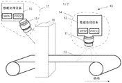
Fig. 1 shows an embodiment of the invention, wherein a machine vision system 10 is disclosed in connection with an object 13 to be monitored. The machine vision system comprises at least two smart cameras 14, 17 comprising image sensors 11, 15 and data processing device parts 12, 16. The area image sensor 11 is arranged to capture images from the object to be monitored (i.e. the movable wall-like material) and to send the image data of each image to the data processing device part 12 of the smart camera 14. The area image sensor 15 is arranged to capture images from the object i to be monitored and to send the image data of each image to the data processing device part 16 of the smart camera 17.
The data processing device part 12, 16 comprises at least one processor, at least one memory including computer program code for one or more program elements and means (e.g. a receiver or transceiver) for receiving image data from the sensor 11 wirelessly or via a wired connection, and means (e.g. a transmitter or transceiver) for sending a trigger signal wirelessly or via a wired connection. There may be multiple processors, such as general purpose processors and graphics processors, as well as DSP processors and/or multiple different memories, such as volatile memories for storing data and programs at runtime and non-volatile memories such as a hard disk for persistently storing data and programs. The data processing device part 12 of the smart camera 14 and the data processing device part 16 of the smart camera 17 may be any computing device suitable for processing image data, such as a computer. The data processing device sections 12, 16 are in electronic communication with the area image sensors 11, 15 via signal lines, respectively. The smart cameras 14, 17 may also include a video controller and an audio controller for generating signals that may be generated for a user having a computer accessory. The smart cameras 14, 17 produce output to the user through output devices. The video controller may be connected to a display. The display may be, for example, a flat panel display or a projector for producing larger images. The audio controller may be connected to a sound source, such as a speaker or headphones. The smart cameras 14, 17 may also include acoustic sensors, such as microphones.
The data processing device part 12, 16 is configured to receive, as image data, images captured by the image sensor 11, 15 at a first image capturing frequency from the image sensor 11, 15. The data processing device part 12, 16 analyzes the above-mentioned images and, if for example the data processing device part 12 detects a deviation, it may configure the image sensor 11 or alternatively the second image sensor 15 of the second camera 16 or both by a trigger signal by indicating an image burst that should be captured and image burst data that should be sent to the data processing device part 12, 16 for further analysis, i.e. an image burst that the data processing device part 12 requests from the image sensor 11 and/or from the image sensor 15 to the processing device part 16. During an image burst, image sensor(s) 11 and/or 15 capture images at a second image capture frequency that is higher than the first image capture frequency. The data processing device section 12 may also define the number of images of an image burst or the duration of an image burst for the image sensor(s) 11 and/or 15 in the trigger signal, or it may be predetermined for the image sensor(s) 11 and/or 15. After the requested image burst has been captured by image sensor(s) 11 and/or 15, image sensor(s) 11 and/or 15 begin capturing images at the first image capture frequency and transmitting image data until the next image burst trigger signal is received. In this embodiment, the second image sensor 15 captures an image of an object to be monitored, which is a machine 18 arranged in front of the image sensor 11 in the production line. Furthermore, since the machine 18 is located earlier in the process than the position in which the deviation is found by the image sensor 11, it is possible, for example, to check whether the machine 18 is working properly or whether the machine 18 causes a deviation of the material web. The data processing device portion 12 may also be arranged to inform a user of the machine comprising the machine vision system 10.
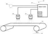
Fig. 2 shows an embodiment of the invention, wherein a machine vision system 20 is disclosed in connection with a moving object 23 to be monitored. The machine vision system comprises at least two image sensors 21, 25, an acoustic sensor 26 and a data processing device 22 for processing acoustic data and image data. The image sensors 21, 25 are arranged to capture images from a moving object 23 being a wall of material and to send data of each image to the data processing device 22. The acoustic sensor 26 is arranged to capture acoustic data around the moving object 23 to be monitored.
The data processing device 22 comprises at least one processor, at least one memory including computer program code for one or more program elements, and means for receiving image data wirelessly or via a wired connection (e.g. a receiver or transceiver) and means for sending the configuration by a trigger signal wirelessly or via a wired connection (e.g. a transmitter or transceiver). There may be multiple processors, such as general purpose processors and graphics processors, as well as DSP processors and/or multiple different memories, such as volatile memories for storing data and programs at runtime and non-volatile memories such as a hard disk for persistently storing data and programs. The data processing device 22 may be any computing device suitable for processing image data, such as a computer. The data processing device 22 is in electronic communication with the image sensors 21, 25 and the acoustic sensor 26 via signal lines. To process signals to/from the signal lines, the data processing device 22 includes I/O circuitry. The connections between the image sensors 21, 25 and the acoustic sensor 26 and the data processing device 22 and between the acoustic sensor 26 and the data processing device 22 are wired or wireless networks. The data processing device 22 may also include a video controller and an audio controller for generating signals that may be generated to a user with a computer accessory. The video controller may be connected to a display. The display may be, for example, a flat panel display or a projector for producing larger images. The audio controller may be connected to a sound source, such as a speaker or headphones. The data processing device 22 may also include an acoustic sensor, such as a microphone.
The data processing device 22 is configured to receive from the image sensors 21, 25 images captured at a first image capture frequency and acoustic data captured by the acoustic sensor 26. The data processing device 22 analyzes the above-mentioned image and acoustic data and if the data processing device 22 detects a deviation, it may configure the image sensor 21 or alternatively the second image sensor 25 or both by a trigger signal indicating that an image burst should be captured and image burst data that should be sent to the data processing device 22 for further analysis (i.e. the data processing device 22 requests an image burst from the image sensor 21 and/or from the image sensor 25). During an image burst, image sensor(s) 21 and/or 25 capture images at a second image capture frequency that is higher than the first image capture frequency.
In this embodiment, a second image sensor 25 is arranged in the production line before the image sensor 21 for imaging the object 23 to be monitored. Therefore, if the data processing device 22 detects a deviation of the image data received from the image sensor 21, it is possible that there is an error in the moving object 23 to be monitored already in an earlier stage of the process and the second image sensor 25 is triggered to perform an image burst.
The data processing device 22 may also define the number of images of an image burst or the duration of an image burst for the image sensor(s) 21 and/or 25, or it may be predetermined for the image sensor(s) 21 and/or 25. After the image sensor(s) 21 and/or 25 have captured and the image data has sent the requested image burst data, the image sensor(s) 21 and/or 25 begin capturing and at the first image capture frequency until the next image burst trigger signal is received. The data processing device 22 may also be arranged to notify a user of a machine comprising the machine vision system 20.
Some image sensors may also provide the possibility of having a plurality of predetermined configuration sets, which, if used, may speed up the process of reconfiguring the image sensors 21, 25 into different modes. In case of a predetermined set of configurations, instead of a list of parameters, a simple command from the data processing device 22 would be sufficient to reconfigure the image sensors 21, 25 to perform an image burst. It is also possible that the image sensor automatically switches to the image burst mode without a trigger signal or any other command (e.g. at a predetermined moment).
It is also possible to use several image burst mode types in one machine vision system, e.g. the image capture frequency or image burst length used or the number of image bursts may vary and they may depend on the root cause, e.g. imaging target or deviation. Again, the data processing apparatus may determine what image burst mode to use for the image sensors (e.g., by a trigger signal), or may predetermine the type of image burst mode for each image sensor in advance. If the image burst mode type is predetermined in advance, it may be sufficient to receive a simple trigger signal indicating only that a change to the image burst state mode is required.
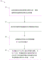
Fig. 3 illustrates a deviation checking method 30 of a machine vision system according to an example embodiment. In step 31, an image sensor of a machine vision system captures images of an object to be monitored at a first image capture frequency. In step 32, the image data processing apparatus transmits the captured image data to the image data processing apparatus. In step 33 the image data processing device analyzes the received image data and if it is detected that the received image data comprises a deviation, the image data processing device sends in step 34 a trigger signal for triggering the image sensors such that at least one image sensor is reconfigured to capture image bursts at the second image capturing frequency and to send the captured image burst data to the image data processing device for further analysis. It should be noted that the image sensor may also be used for imaging other types of moving object(s) than wall-like materials.
Various embodiments of the present invention may be implemented by means of computer program code located in a memory and causing an apparatus to perform the invention. For example, an apparatus being a computing device, e.g., a data processing device, may comprise circuitry and electronics for analyzing, receiving and transmitting data, computer program code in a memory, and a processor that, when running the computer program code, causes the apparatus to perform the features of an embodiment. When executing the computer program code, the processor may perform the steps of the method of: capturing, by an image sensor, e.g. a camera sensor, an image(s) of an object to be monitored at a first image capturing frequency, transmitting image data of said captured images, analyzing the received images, and if it is detected that said received images comprise deviations or if it is detected that the mechanical acoustic representation comprises changes, the data processing device is arranged to transmit a configuration to at least one image sensor by means of a trigger signal, and wherein said at least one image sensor is arranged to capture image bursts imaged during a relatively short period of time at a second image capturing frequency. After the image burst, the image sensor continues to image at the first image capture frequency. The method may further comprise the step wherein the data processing device is arranged to store and send image data of said image burst to the data processing device for further analysis. It should be noted that a defect in the image or a change in the mechanical acoustic representation may not always be required to cause the data processing device to trigger an image burst, but the image burst may also be triggered randomly by the data processing device.
Considerable advantages are achieved by the present invention when compared to methods and systems of existing machine vision systems that include at least an image sensor, such as a camera adapted to capture bursts of images. By means of the arrangement according to the invention, it is possible to use the image sensor in two different modes, wherein the first mode comprises imaging at a first image capturing frequency and the second mode comprises imaging at a second image capturing frequency for a short period of time when required. In addition, with the arrangement according to the invention it is also possible to provide image burst data when needed (e.g. when separate and less frequently captured images do not give sufficient information).
It is obvious that the invention is not exclusively limited to the embodiments presented above, but that it can be modified within the scope of the appended claims.
Claims (13)
1. A machine vision method, comprising:
capturing, by an image sensor of a machine vision system, an image of an object to be monitored at a first image capture frequency;
transmitting the captured image data to a data processing device; and
analyzing the received image data by the data processing device, and wherein
If it is detected that the received image data comprises a deviation, the data processing device is arranged to send a trigger signal for triggering at least the image sensor capturing the image data comprising the deviation, such that at least the image sensor is reconfigured to capture image bursts at a second image capture frequency, wherein the trigger signal defines a duration of the image bursts, and wherein the second image capture frequency of the image bursts is higher than the first image capture frequency, and is reconfigured to send the captured image burst data to the data processing device for further analysis.
2. The method of claim 1, wherein the method further comprises:
recording an acoustic environment surrounding the machine vision system;
transmitting recorded acoustic environment data comprising an acoustic representation of a process machine to the data processing device; and
analyzing the received acoustic environment data by the data processing device, and wherein
If it is detected that the received acoustic environment data comprises a change in the acoustic representation of the process machine during a first image capture mode, the data processing device is arranged to send a trigger signal for triggering an image sensor such that at least one image sensor is reconfigured to capture image bursts at the second image capture frequency and send the captured image burst data to the data processing device for further analysis.
3. The method according to claim 1 or 2, wherein the method further comprises:
defining a correlation between deviations of the objects to be monitored and their causes;
determining a cause of the detected deviation; and
determining, based on the reason, the image sensor reconfigured to capture the burst of images, wherein the image sensor is in a position that: in which position the cause causes the detected deviation.
4. The method of claim 1 or 2, wherein the image sensor continues to capture images at the first image capture frequency after the burst of images.
5. The method of claim 1 or 2, wherein the trigger signal determines an image capture frequency of the image burst.
6. The method of claim 1 or 2, wherein the trigger signal determines an image resolution of images captured during the image burst.
7. A machine vision system for monitoring an object to be monitored, comprising an image sensor and a data processing device, wherein the image sensor is arranged to capture images of the object to be monitored at a first image capture frequency and to send captured image data to the data processing device for analysis, and wherein if it is detected that the received image data comprises a deviation, the data processing device is arranged to send a trigger signal for triggering at least the image sensor that captures the image data comprising the deviation, such that at least the image sensor is reconfigured to capture image bursts at a second image capture frequency, wherein the trigger signal defines a duration of the image bursts, and wherein the second image capture frequency of the image bursts is higher than the first image capture frequency, and is reconfigured to send the captured image burst data to the data processing apparatus for further analysis.
8. The machine vision system of claim 7, wherein the machine vision system further comprises an acoustic sensor, wherein the acoustic sensor is arranged to record an acoustic environment surrounding the machine vision system, and wherein the acoustic sensor is further arranged to transmit recorded acoustic environment data comprising an acoustic representation of the process machine to the data processing device for analysis, and wherein if it is detected that the received acoustic environment data comprises a change in the acoustic representation of the process machine during the first image capture mode, the data processing apparatus is arranged to send a trigger signal for triggering the image sensors such that at least one image sensor is reconfigured to capture image bursts at the second image capture frequency, and sending the captured image burst data to the data processing device for further analysis.
9. The machine-vision system of claim 7 or 8, wherein the data processing device further:
defining a correlation between deviations of the objects to be monitored and their causes;
determining a cause of the detected deviation; and
determining, based on the reason, the image sensor reconfigured to capture the burst of images, wherein the image sensor is in a position that: in which position the cause causes the detected deviation.
10. The machine-vision system of claim 7 or 8, wherein the image sensor continues to capture images at the first image capture frequency after the burst of images.
11. The machine-vision system of claim 7 or 8, wherein the trigger signal determines an image capture frequency of the image bursts.
12. The machine-vision system of claim 7 or 8, wherein the trigger signal determines an image resolution of images captured during the image burst.
13. A computer readable storage medium having instructions stored thereon, wherein the instructions, when executed by a processor, implement the steps of a method according to claim 1 or 2.
Applications Claiming Priority (3)
| Application Number | Priority Date | Filing Date | Title |
|---|---|---|---|
| FI20165389 | 2016-05-06 | ||
| FI20165389A FI128735B (en) | 2016-05-06 | 2016-05-06 | A machine vision method and system |
| PCT/FI2017/050322 WO2017191361A1 (en) | 2016-05-06 | 2017-04-28 | A machine vision method and system |
Publications (2)
| Publication Number | Publication Date |
|---|---|
| CN109416315A CN109416315A (en) | 2019-03-01 |
| CN109416315B true CN109416315B (en) | 2021-10-15 |
Family
ID=60202809
Family Applications (1)
| Application Number | Title | Priority Date | Filing Date |
|---|---|---|---|
| CN201780028097.9A Active CN109416315B (en) | 2016-05-06 | 2017-04-28 | Machine vision method and system |
Country Status (6)
| Country | Link |
|---|---|
| US (1) | US10451562B2 (en) |
| EP (1) | EP3452806B1 (en) |
| JP (1) | JP6902051B2 (en) |
| CN (1) | CN109416315B (en) |
| FI (1) | FI128735B (en) |
| WO (1) | WO2017191361A1 (en) |
Families Citing this family (5)
| Publication number | Priority date | Publication date | Assignee | Title |
|---|---|---|---|---|
| JP6333871B2 (en) * | 2016-02-25 | 2018-05-30 | ファナック株式会社 | Image processing apparatus for displaying an object detected from an input image |
| DE102018107689A1 (en) * | 2018-03-29 | 2019-10-02 | Krones Ag | Method and device for inspecting containers |
| CN109001225B (en) * | 2018-04-27 | 2023-07-11 | 上海宝钢工业技术服务有限公司 | Device and method for detecting fatigue crack of crane beam of crane |
| CN113138191B (en) * | 2020-01-20 | 2022-08-05 | 上海各瑟信息科技有限公司 | System and method for analyzing name of detection object part |
| CN113298057B (en) * | 2021-07-27 | 2021-10-01 | 浙江力嘉电子科技有限公司 | Exception detection method and device for off-site law enforcement system, electronic device and storage medium |
Citations (9)
| Publication number | Priority date | Publication date | Assignee | Title |
|---|---|---|---|---|
| US5040057A (en) * | 1990-08-13 | 1991-08-13 | Picker International, Inc. | Multi-mode TDI/raster-scan television camera system |
| CA2088816C (en) * | 1992-02-07 | 2000-03-28 | Roger-Henri Roch | Device for detecting print misregisters, arranged in a rotary printing machine |
| CN1668081A (en) * | 2005-05-10 | 2005-09-14 | 北京中星微电子有限公司 | A shooting method and device for monitoring |
| CN101002229A (en) * | 2004-06-09 | 2007-07-18 | 科格内克斯科技及投资公司 | Method and apparatus for improved vision detector image capture and analysis |
| WO2007096475A1 (en) * | 2006-02-22 | 2007-08-30 | Viconsys Oy | Method for monitoring a rapidly-moving paper web and corresponding system |
| EP2042654A2 (en) * | 2007-09-26 | 2009-04-01 | Voith Patent GmbH | Band calendar device and method for operating a band calendar device |
| CN102656445A (en) * | 2009-12-16 | 2012-09-05 | 宝洁公司 | Systems and methods for monitoring on-line webs using line scan cameras |
| WO2015001196A1 (en) * | 2013-07-05 | 2015-01-08 | Procemex Oy | Synchronization of imaging |
| CN105141922A (en) * | 2015-09-02 | 2015-12-09 | 广东美的制冷设备有限公司 | Security monitoring method based on air conditioner and air conditioner |
Family Cites Families (14)
| Publication number | Priority date | Publication date | Assignee | Title |
|---|---|---|---|---|
| JPH10294933A (en) * | 1997-04-18 | 1998-11-04 | Mitsubishi Electric Corp | Video monitoring system |
| JP3581566B2 (en) * | 1998-06-10 | 2004-10-27 | 株式会社日立製作所 | Monitoring system |
| JP2001276027A (en) * | 2000-03-29 | 2001-10-09 | Hitachi Medical Corp | Digital radiographic instrument |
| US6750466B2 (en) | 2001-02-09 | 2004-06-15 | Wintriss Engineering Corporation | Web inspection system |
| US20050276445A1 (en) | 2004-06-09 | 2005-12-15 | Silver William M | Method and apparatus for automatic visual detection, recording, and retrieval of events |
| FI119708B (en) * | 2006-02-01 | 2009-02-13 | Viconsys Oy | Device for checking a path |
| US7983933B2 (en) * | 2006-12-06 | 2011-07-19 | Microsoft Corporation | Patient monitoring via image capture |
| US8213685B2 (en) * | 2007-01-05 | 2012-07-03 | American Traffic Solutions, Inc. | Video speed detection system |
| JP5377482B2 (en) * | 2008-06-23 | 2013-12-25 | 三菱電機株式会社 | In-train monitoring system and in-train monitoring method |
| DE202010008084U1 (en) | 2010-07-15 | 2011-10-21 | Eltromat Gmbh | Device for monitoring the printing result in rotary printing machines |
| WO2014144628A2 (en) * | 2013-03-15 | 2014-09-18 | Master Lock Company | Cameras and networked security systems and methods |
| CA2942852C (en) * | 2013-03-15 | 2023-03-28 | Interaxon Inc. | Wearable computing apparatus and method |
| US9244042B2 (en) * | 2013-07-31 | 2016-01-26 | General Electric Company | Vibration condition monitoring system and methods |
| US9245187B1 (en) * | 2014-07-07 | 2016-01-26 | Geo Semiconductor Inc. | System and method for robust motion detection |
-
2016
- 2016-05-06 FI FI20165389A patent/FI128735B/en active IP Right Grant
-
2017
- 2017-04-28 WO PCT/FI2017/050322 patent/WO2017191361A1/en unknown
- 2017-04-28 JP JP2018558158A patent/JP6902051B2/en active Active
- 2017-04-28 EP EP17792557.5A patent/EP3452806B1/en active Active
- 2017-04-28 US US16/093,724 patent/US10451562B2/en active Active
- 2017-04-28 CN CN201780028097.9A patent/CN109416315B/en active Active
Patent Citations (9)
| Publication number | Priority date | Publication date | Assignee | Title |
|---|---|---|---|---|
| US5040057A (en) * | 1990-08-13 | 1991-08-13 | Picker International, Inc. | Multi-mode TDI/raster-scan television camera system |
| CA2088816C (en) * | 1992-02-07 | 2000-03-28 | Roger-Henri Roch | Device for detecting print misregisters, arranged in a rotary printing machine |
| CN101002229A (en) * | 2004-06-09 | 2007-07-18 | 科格内克斯科技及投资公司 | Method and apparatus for improved vision detector image capture and analysis |
| CN1668081A (en) * | 2005-05-10 | 2005-09-14 | 北京中星微电子有限公司 | A shooting method and device for monitoring |
| WO2007096475A1 (en) * | 2006-02-22 | 2007-08-30 | Viconsys Oy | Method for monitoring a rapidly-moving paper web and corresponding system |
| EP2042654A2 (en) * | 2007-09-26 | 2009-04-01 | Voith Patent GmbH | Band calendar device and method for operating a band calendar device |
| CN102656445A (en) * | 2009-12-16 | 2012-09-05 | 宝洁公司 | Systems and methods for monitoring on-line webs using line scan cameras |
| WO2015001196A1 (en) * | 2013-07-05 | 2015-01-08 | Procemex Oy | Synchronization of imaging |
| CN105141922A (en) * | 2015-09-02 | 2015-12-09 | 广东美的制冷设备有限公司 | Security monitoring method based on air conditioner and air conditioner |
Also Published As
| Publication number | Publication date |
|---|---|
| FI128735B (en) | 2020-11-13 |
| FI20165389A (en) | 2017-11-07 |
| CN109416315A (en) | 2019-03-01 |
| WO2017191361A1 (en) | 2017-11-09 |
| EP3452806A4 (en) | 2020-02-05 |
| JP2019517193A (en) | 2019-06-20 |
| US10451562B2 (en) | 2019-10-22 |
| EP3452806B1 (en) | 2023-07-26 |
| US20190137410A1 (en) | 2019-05-09 |
| EP3452806C0 (en) | 2023-07-26 |
| EP3452806A1 (en) | 2019-03-13 |
| JP6902051B2 (en) | 2021-07-14 |
Similar Documents
| Publication | Publication Date | Title |
|---|---|---|
| CN109416315B (en) | Machine vision method and system | |
| JP2018032396A5 (en) | ||
| EP3452811B1 (en) | A machine vision method and system for monitoring manufacturing processes | |
| US10440217B2 (en) | Apparatus and method for processing three dimensional image | |
| WO2017191362A1 (en) | Acoustic analysation of an operational state of process machinery | |
| US20160142682A1 (en) | Synchronization of Imaging | |
| CN106961514A (en) | Terminal installation and information output method | |
| JP2018055370A (en) | Inspection device | |
| JP2019517193A5 (en) | ||
| KR20100117793A (en) | Apparatus for analyzing sound source | |
| WO2020141253A1 (en) | A method of using a machine-readable code for instructing camera for detecting and monitoring objects | |
| JP6995633B2 (en) | Molded product take-out system | |
| US20230228691A1 (en) | Smart synchronization method of a web inspection system | |
| US9172916B2 (en) | Web monitoring system | |
| JP2021128110A (en) | Belt conveyor monitoring device | |
| KR101830331B1 (en) | Apparatus for detecting abnormal operation of machinery and method using the same | |
| FI128820B (en) | A machine vision method and system for monitoring manufacturing processes | |
| KR102542068B1 (en) | Apparatus and method for generating triger signal | |
| KR102180506B1 (en) | Camera device supporting automatic image correction for noise included in image | |
| JP6770052B2 (en) | Structure soundness evaluation device | |
| JP2003114166A (en) | Method and apparatus for detection of decentering of compound lens | |
| WO2022073553A3 (en) | Device and method for monitoring surfaces or spaces | |
| JP2012012127A (en) | Device for monitoring inside of elevator car | |
| JP2023084862A (en) | Ultrasonic diagnostic device and control method of ultrasonic diagnostic device | |
| KR20210065619A (en) | Image analysis apparatus |
Legal Events
| Date | Code | Title | Description |
|---|---|---|---|
| PB01 | Publication | ||
| PB01 | Publication | ||
| SE01 | Entry into force of request for substantive examination | ||
| SE01 | Entry into force of request for substantive examination | ||
| GR01 | Patent grant | ||
| GR01 | Patent grant |