CN109154259B - Fuel supply device - Google Patents
Fuel supply device Download PDFInfo
- Publication number
- CN109154259B CN109154259B CN201780026010.4A CN201780026010A CN109154259B CN 109154259 B CN109154259 B CN 109154259B CN 201780026010 A CN201780026010 A CN 201780026010A CN 109154259 B CN109154259 B CN 109154259B
- Authority
- CN
- China
- Prior art keywords
- main body
- detection unit
- fuel
- rotation
- liquid level
- Prior art date
- Legal status (The legal status is an assumption and is not a legal conclusion. Google has not performed a legal analysis and makes no representation as to the accuracy of the status listed.)
- Active
Links
Images


Classifications
-
- F—MECHANICAL ENGINEERING; LIGHTING; HEATING; WEAPONS; BLASTING
- F02—COMBUSTION ENGINES; HOT-GAS OR COMBUSTION-PRODUCT ENGINE PLANTS
- F02M—SUPPLYING COMBUSTION ENGINES IN GENERAL WITH COMBUSTIBLE MIXTURES OR CONSTITUENTS THEREOF
- F02M37/00—Apparatus or systems for feeding liquid fuel from storage containers to carburettors or fuel-injection apparatus; Arrangements for purifying liquid fuel specially adapted for, or arranged on, internal-combustion engines
- F02M37/04—Feeding by means of driven pumps
- F02M37/08—Feeding by means of driven pumps electrically driven
- F02M37/10—Feeding by means of driven pumps electrically driven submerged in fuel, e.g. in reservoir
-
- F—MECHANICAL ENGINEERING; LIGHTING; HEATING; WEAPONS; BLASTING
- F02—COMBUSTION ENGINES; HOT-GAS OR COMBUSTION-PRODUCT ENGINE PLANTS
- F02M—SUPPLYING COMBUSTION ENGINES IN GENERAL WITH COMBUSTIBLE MIXTURES OR CONSTITUENTS THEREOF
- F02M37/00—Apparatus or systems for feeding liquid fuel from storage containers to carburettors or fuel-injection apparatus; Arrangements for purifying liquid fuel specially adapted for, or arranged on, internal-combustion engines
- F02M37/0011—Constructional details; Manufacturing or assembly of elements of fuel systems; Materials therefor
-
- F—MECHANICAL ENGINEERING; LIGHTING; HEATING; WEAPONS; BLASTING
- F02—COMBUSTION ENGINES; HOT-GAS OR COMBUSTION-PRODUCT ENGINE PLANTS
- F02M—SUPPLYING COMBUSTION ENGINES IN GENERAL WITH COMBUSTIBLE MIXTURES OR CONSTITUENTS THEREOF
- F02M37/00—Apparatus or systems for feeding liquid fuel from storage containers to carburettors or fuel-injection apparatus; Arrangements for purifying liquid fuel specially adapted for, or arranged on, internal-combustion engines
- F02M37/04—Feeding by means of driven pumps
- F02M37/08—Feeding by means of driven pumps electrically driven
- F02M37/10—Feeding by means of driven pumps electrically driven submerged in fuel, e.g. in reservoir
- F02M37/103—Mounting pumps on fuel tanks
-
- F—MECHANICAL ENGINEERING; LIGHTING; HEATING; WEAPONS; BLASTING
- F02—COMBUSTION ENGINES; HOT-GAS OR COMBUSTION-PRODUCT ENGINE PLANTS
- F02M—SUPPLYING COMBUSTION ENGINES IN GENERAL WITH COMBUSTIBLE MIXTURES OR CONSTITUENTS THEREOF
- F02M37/00—Apparatus or systems for feeding liquid fuel from storage containers to carburettors or fuel-injection apparatus; Arrangements for purifying liquid fuel specially adapted for, or arranged on, internal-combustion engines
- F02M37/04—Feeding by means of driven pumps
- F02M37/08—Feeding by means of driven pumps electrically driven
- F02M37/10—Feeding by means of driven pumps electrically driven submerged in fuel, e.g. in reservoir
- F02M37/106—Feeding by means of driven pumps electrically driven submerged in fuel, e.g. in reservoir the pump being installed in a sub-tank
Landscapes
- Engineering & Computer Science (AREA)
- Chemical & Material Sciences (AREA)
- Combustion & Propulsion (AREA)
- Mechanical Engineering (AREA)
- General Engineering & Computer Science (AREA)
- Level Indicators Using A Float (AREA)
- Cooling, Air Intake And Gas Exhaust, And Fuel Tank Arrangements In Propulsion Units (AREA)
Abstract
The fuel supply device (100) comprises a liquid level detector (40), and the liquid level detector (40) detects the height of the liquid level by using a floating body (60) floating on the fuel. A supply main body part (20a) of the fuel supply device (100) is arranged inside a fuel tank (90) through an insertion opening (92), and supplies fuel to the outside of the fuel tank (90). The liquid level detection unit (50) having the float (60) is capable of rotating relative to the supply main body (20a), and the range of rotation is defined so as to include at least the Insertion Direction (ID) of the supply main body (20 a). A distal end portion (50a) of the liquid surface detection unit (50) that is farthest from the virtual center axis of rotation (Ar2) is disposed above a Virtual Plane (VP) that includes the center axis of rotation (Ar2) and the Center of Gravity (CG) of the liquid surface detection unit (50) in the direction of rotation of the liquid surface detection unit (50).
Description
Cross reference to related applications
The present application is based on Japanese patent application No. 2016-.
Technical Field
The present invention relates to a fuel supply device that is disposed in a fuel tank and supplies fuel in the fuel tank to an internal combustion engine.
Background
Conventionally, for example, patent document 1 discloses a fuel supply device including a fuel gauge (sender gauge) that detects a liquid level of fuel using a float (float). The fuel gauge includes a main body fixed to a pump unit of the fuel supply device, and a gauge arm (gauge arm) and a liquid level detecting unit such as a float, which are rotatable relative to the pump unit. The pump unit and the fuel gauge of the fuel supply device are inserted into the fuel tank through the insertion opening, and are disposed inside the fuel tank.
Generally, a main body of the fuel gauge is provided with a stopper (stopper) that regulates a rotation range of the liquid level detection unit by regulating a displacement of the rotatable liquid level detection unit. As in patent document 1, the rotation range of the liquid level detection unit is defined to include at least the insertion direction of the pump unit. Therefore, when the pump unit or the like is inserted into the fuel tank, the float attached to the tip end side of the liquid level detection unit comes into contact with the bottom wall surface of the fuel tank and receives a reaction force from the bottom wall surface.
Here, the float body of patent document 1 is shaped so as to have a larger volume on the lower side than on the upper side in the rotation direction, so that even when the remaining amount of the fuel stored in the fuel tank becomes small, the float body can follow the height of the liquid surface even in the vicinity of the bottom wall surface due to the buoyancy received from the fuel. Therefore, when the float interferes with the bottom wall surface during the insertion operation, the liquid level detection unit is rotated downward by a force acting on the float from the bottom wall surface, and strongly comes into close contact with the regulating portion that regulates displacement in the downward direction. As a result, the liquid level detection unit, the regulating portion, and the like may be damaged.
Documents of the prior art
Patent document
Disclosure of Invention
The present invention has been made in view of the above problems, and an object of the present invention is to provide a fuel supply device that can avoid damage to a liquid level detection unit, a regulating portion, and the like before use.
In order to achieve the above object, a first aspect of the present invention is a fuel supply device in which a supply body is inserted into an insertion opening provided in a fuel tank in a posture in which a specific insertion direction is oriented toward the insertion opening, the fuel supply device including a liquid level detector for detecting a height of a liquid level by a float floating in fuel, the fuel supply device including: a supply main body section having a lower limit regulating section for regulating downward displacement of the floating body, disposed inside the fuel tank, and supplying fuel to the outside of the fuel tank; and a liquid surface detection unit having a float and being capable of rotating relative to the supply body, the rotation in the downward direction being restricted by contact with the lower limit restricting portion, the rotation range being defined to include at least a space in the insertion direction of the supply body, and a tip end portion of the liquid surface detection unit, which is farthest from the virtual rotation center axis, being provided above a virtual plane including the rotation center axis and a center of gravity of the liquid surface detection unit in the rotation direction of the liquid surface detection unit.
According to this aspect, during the insertion operation of inserting the supply body of the fuel supply device into the fuel tank, the liquid level detection means is in a posture in which a part thereof is positioned in the insertion direction of the supply body and the center of gravity is positioned in the gravity direction of the virtual rotation center axis. At this time, a tip portion of the liquid level detection means, which is farthest from the rotation central axis, is located on an upper side in the rotation direction with respect to a virtual plane including the rotation central axis and the center of gravity. Therefore, even when the tip end portion interferes with the bottom wall surface of the fuel tank by the insertion operation, the liquid level detection unit is rotated upward by the force acting from the bottom wall surface. If the rotation of the liquid level detection unit in the downward direction is prevented in this way, the liquid level detection unit can be prevented from being strongly adhered to the lower limit stopper by the force acting from the bottom wall surface of the fuel tank. Therefore, damage to the liquid level detection unit, the regulating portion, and the like before use of the fuel supply device can be avoided.
Drawings
The above and other objects, features and advantages of the present invention will become more apparent from the following detailed description with reference to the accompanying drawings.
Fig. 1 is a diagram showing a state in which a fuel supply device according to a first embodiment is installed in a fuel tank.
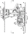
Fig. 2 is a sectional view taken along line II-II of fig. 1.
Fig. 3 is a perspective view of the liquid level detector.
Fig. 4 is a view showing a process of mounting the fuel supply device to the fuel tank.
Fig. 5 is a view showing a process of mounting the fuel supply device to the fuel tank.
Fig. 6 is a view showing a process of mounting the fuel supply device to the fuel tank.
Fig. 7 is a view showing a process of mounting the fuel supply device to the fuel tank.
Fig. 8 is a view showing a process of mounting the fuel supply device to the fuel tank.
Fig. 9 is a view showing a process of mounting the fuel supply device to the fuel tank.
Fig. 10 is a view showing a process of mounting the fuel supply device to the fuel tank.
Fig. 11 is a diagram showing a state in which the fuel supply device of the second embodiment is installed in a fuel tank.
Fig. 12 is a sectional view taken along line XII-XII of fig. 11.
Fig. 13 is a diagram schematically showing the configuration of the liquid level detection unit according to modification 1.
Fig. 14 is a diagram schematically showing the configuration of the liquid level detection unit according to modification 2.
Detailed Description
Embodiments of the present invention will be described below with reference to the drawings. In each embodiment, corresponding components are denoted by the same reference numerals, and redundant description thereof may be omitted. In the case where only a part of the configuration is described in each embodiment, the configuration of the other embodiment described above can be applied to the other part of the configuration. In addition, not only the combinations of the configurations explicitly described in the description of the respective embodiments, but also the configurations of the plurality of embodiments may be partially combined with each other without explicit description as long as no particular obstacle is generated in the combination. Further, combinations of the configurations described in the embodiments and the modifications, which are not explicitly shown, are also considered to be disclosed in the following description.
(first embodiment)
A fuel supply apparatus 100 according to a first embodiment of the present invention shown in fig. 1 is provided inside a fuel tank 90. The fuel tank 90 is formed of a resin material or a metal material in a hollow shape. The fuel tank 90 is mounted on the vehicle together with the internal combustion engine 110, and stores liquid fuel such as gasoline or light oil that is consumed by the internal combustion engine 110. A circular insertion opening 92 is provided in a top wall 91 of the fuel tank 90. A part of the structure of the fuel supply apparatus 100 is inserted into the interior of the fuel tank 90 through the insertion opening 92. The vertical direction of the structure disposed inside the fuel tank 90 substantially coincides with the vertical direction of the vehicle stopped on the horizontal plane.
As shown in fig. 1 and 2, the fuel supply apparatus 100 includes a flange (flange)10, a sub-tank 20, a column 30, a liquid level detector 40, and the like.
The flange 10 is formed of a resin material into a circular plate shape as a whole. The flange 10 is attached to a top wall 91 of the fuel tank 90 so as to close off the insertion opening 92. The flange 10 is formed with a fuel supply pipe 11 and a connector 12. The fuel supply pipe 11 forms a fuel path through which the fuel supplied from the sub-tank 20 flows toward the internal combustion engine 110. A plug portion electrically connected to the control circuit system 120 is fitted to the connector 12.
The sub-tank 20 is housed inside the fuel tank 90 and is located below the flange 10. The sub-tank 20 is formed in an elongated shape as a whole, and is pressed against a bottom wall surface 94 of a bottom wall 93 of the fuel tank 90 in an installation posture in which the longitudinal direction is along the bottom wall surface 94 (hereinafter referred to as "bottom wall surface"). The sub-tank 20 includes a sub-tank body 21 and a fuel pump 22.
The sub-tank body 21 is formed in a flat rectangular parallelepiped shape as a whole. The sub-tank body 21 is placed on the bottom wall surface 94 of the fuel tank 90. The fuel stored in the fuel tank 90 flows into the sub-tank main body 21. The sub-tank body 21 temporarily stores the fuel sucked by the fuel pump 22.
The fuel pump 22 is an electric pump such as a vane pump or a trochoid pump. The fuel pump 22 is formed in a cylindrical shape as a whole. The fuel pump 22 is fixed to the sub-tank main body 21 in a posture in which the axial direction is along the longitudinal direction of the sub-tank 20. The fuel pump 22 is connected to the connector 12 via flexible wiring that is freely bent. Control signals are supplied from the control circuitry 120 to the fuel pump 22 via the connection 12. The control circuit system 120 controls the operation of the fuel pump 22 for sucking the fuel stored in the sub-tank main body 21. The fuel pump 22 supplies the fuel sucked into the fuel tank 90 to the internal combustion engine 110 outside the fuel tank 90.
The strut 30 is housed inside the fuel tank 90. The strut 30 mechanically couples the flange 10 and the sub-tank 20 separately. The strut 30 rotatably supports the sub-tank 20. The strut 30 includes a lower strut part 31, an upper strut part 32, an elastic member 33, and the like.
Lower support column part 31 and upper support column part 32 are formed of a resin material. The lower pillar portion 31 is attached to the sub-tank body 21. The lower support pillar portion 31 is rotatable relative to the sub-tank body portion 21 about a virtual body rotation axis Ar 1. With the structure of the lower support column portion 31, the support column 30 rotatably supports the sub-tank 20 about the body rotation axis Ar1 as a rotation center. The body rotation axis Ar1 is defined at a position offset to one side from the center of the sub-tank 20 in the longitudinal direction. When the sub-tank 20 is in the installation posture, the body rotation axis Ar1 is in a posture along the bottom wall surface 94. The upper support column part 32 is formed in a cylindrical shape extending downward from the flange 10. Upper column part 32 is fitted with lower column part 31 by sliding from below.
The elastic member 33 is a coil spring formed of a metal material. The elastic member 33 is disposed in a state of being compressed between the lower column part 31 and the upper column part 32. Elastic member 33 causes a downward restoring force to act on lower support part 31. According to the above configuration, the sub-tank 20 is pressed against the bottom wall 93 by the fixation of the flange 10 to the top wall 91. The relative position of lower support column part 31 and upper support column part 32 can be changed according to expansion and contraction of fuel tank 90.
The liquid level detector 40 shown in fig. 1 to 3 is housed in the fuel tank 90 together with the sub-tank 20. The liquid level detector 40 detects the liquid level of the fuel stored in the fuel tank 90 by using the float 60 floating in the fuel. The liquid level detector 40 includes a detector body (sensor body)41 and a liquid level detection unit 50.
The detector main body 41 is formed of a resin material. The detector body 41 is fixed to the sub-tank 20 by being attached to the sub-tank body 21. The detector main body 41 and the sub-tank 20 constitute a supply main body 20a that rotatably supports the liquid surface detection unit 50. A hall ic (hall ic) is housed in the detector main body 41. The hall IC is a sensor that detects the rotational phase of the liquid level detection unit 50. The detector body 41 is formed with a plurality of pairs of upper limit limiting portions 42 and lower limit limiting portions 43. The upper limit stopper 42 and the lower limit stopper 43 are disposed to face each other in the vertical direction.
The liquid surface detection unit 50 is relatively rotatable around a virtual rotation center axis Ar2 with respect to the supply body portion 20 a. The virtual rotation center axis Ar2 is defined as an attitude along the main body rotation axis Ar 1. Therefore, when the supply body 20a (sub-tank 20) is in the installation posture, the posture is along the bottom wall surface 94. The rotation center axis Ar2 is located above the body rotation axis Ar1 of the supply body 20 a. The rotation center axis Ar2 and the main body rotation axis Ar1 are located on opposite sides with respect to the center of the supply main body 20a in the longitudinal direction.
The liquid level detection unit 50 includes a magnet frame 51, a detector arm (sensor arm)55, and a floating body 60.
The magnet holder 51 is formed of a resin material into a circular plate shape as a whole. A pair of magnets is housed in the magnet holder 51. The pair of magnets are disposed so as to sandwich the hall IC, and a magnetic field is applied to the hall IC. The magnet holder 51 has a plurality of limiting holes 52 formed therein.
The detector arm 55 is formed of a metal material into a round bar shape. One end portion of the detector arm body 55 is bent with respect to the main body portion. The detector arm 55 is attached to the magnet frame 51 in a state where one end portion thereof is inserted into one of the plurality of limiting holes 52. One end portion inserted through the limiting hole 52 is in contact with the upper limit limiting portion 42 and the lower limit limiting portion 43 by the rotation of the liquid level detection unit 50.
The floating body 60 is formed of a material such as foam hard rubber into a flat rectangular parallelepiped shape as a whole. The sides of the float 60 are rounded off with a small (a few millimeters) R. The float 60 is attached to the other end of the detector arm 55. The float 60 can float on the liquid surface of the fuel, slide in a long direction along the liquid surface, and displace in the vertical direction following the change in the liquid surface of the fuel. The liquid level detection unit 50 rotates relative to the supply main body 20a due to the vertical displacement of the float 60.
In the liquid level detection unit 50 described above, one end of the detector arm 55 is in contact with the upper limit stopper 42 due to the upward displacement of the float 60 accompanying the rise in the liquid level. Thereby, the upward displacement of the floating body 60 and the upward rotation of the liquid level detection unit 50 are restricted. As a result, the floating body 60 is prevented from contacting the top wall 91.
Further, due to downward displacement of the float 60 accompanying the liquid level decrease, the end of the detector arm 55 contacts the lower limit stopper 43. Thereby, the downward displacement of the floating body 60 and the downward rotation of the liquid level detection unit 50 are restricted. As a result, the floating body 60 is prevented from contacting the bottom wall 93.
The liquid level detector 40 detects the rotation phase of the liquid level detection unit 50 rotated by the displacement of the float 60 using the hall IC. The hall IC is electrically connected to an in-vehicle device, such as an instrument cluster, provided outside the fuel tank 90. The detection result of the hall IC is acquired by the meter cluster, and information indicating the remaining fuel amount is provided to the driver of the vehicle and the like.
In the fuel supply device 100 described above, the sub-tank 20, the liquid level detector 40, and the like are inserted into the fuel tank 90 through the insertion opening 92 as described above. The structure and function of preventing the liquid level detector 40 from being damaged during such insertion work, and the respective assembly steps including the insertion work will be described below with reference to fig. 4 to 10. Fig. 4 to 10 show a case where the sub-tank 20 and the liquid level detector 40 are inserted into the insertion opening 92 in a posture in which the longitudinal direction of the supply body portion 20a is directed in the vertical direction, as a worst state in which the float 60 is most likely to interfere with the bottom wall surface 94.
Here, the insertion direction ID used in the following description is a direction defined with respect to the supply body 20a, and specifically, is a direction from the body rotation axis Ar1 toward the rotation center axis Ar2 along the longitudinal direction of the supply body 20 a. Note that the "upper side" and the "lower side" used above are relative directions defined with respect to the supply main body portion 20a, and therefore are distinguished from the absolute vertical direction and are also used in the following description. The rotation direction of the liquid level detection unit is also based on the "upper side" and the "lower side" of the supply main body 20a in the set state. That is, in the insertion operation, regardless of the orientation of the supply body 20a, the direction of approach to the ceiling wall 91 in the installed state is the "upper side" and the direction of approach to the bottom wall 93 is the "lower side". Specifically, in fig. 4 to 10 in which the liquid surface detector 40 is viewed from the front, the left side with respect to the rotation center axis Ar2 is the "upper side", and the right side with respect to the rotation center axis Ar2 is the "lower side".
As shown in fig. 4, the form of the fuel supply apparatus 100 at the start of the insertion work (hereinafter referred to as "insertion form") is different from the form of the fuel supply apparatus 100 in a state of being set in the fuel tank 90 (hereinafter referred to as "set form", see fig. 1).
Specifically, the support column 30 in the inserted state is most extended in the axial direction by the restoring force of the elastic member 33 (see fig. 2). In the insertion mode and the installation mode, the relative posture of the supply main body portion 20a with respect to the support column 30 is different. The supply body 20a in the insertion state is in an insertion posture in which the support portion of the liquid level detection unit 50 is rotated downward relative to the support column 30, as compared with the state in the installation state. Specifically, an imaginary line that is along the extending direction of the strut 30 on an imaginary vertical plane orthogonal to the body rotation axis Ar1 and intersects the body rotation axis Ar1 is taken as the strut axis CAL. In addition, a virtual line that is along the longitudinal direction of the supply main body portion 20a and intersects the main body rotation axis Ar1 on the vertical plane is defined as a main body axis BAL. In the vertical plane, the angle formed by the column axis CAL and the main body axis BAL is substantially 90 degrees when the supply main body 20a is in the installation position. On the other hand, when the supply body 20a is in the insertion posture, the angle formed by the stay axis CAL and the body axis BAL is an obtuse angle of 90 degrees or more, for example, as large as about 130 degrees.
The rotation range of the liquid level detection unit 50 is defined so as to include at least a space for supplying the insertion direction ID of the main body portion 20 a. During the insertion operation, the main body portion 20a is supplied and inserted into the insertion opening 92 in a posture in which the specific insertion direction ID is directed toward the insertion opening 92. At this time, the support column 30, the flange 10, and the supply body 20a are held by the operator. On the other hand, the liquid level detection unit 50 is not fixed to the supply body 20a and is not held by the operator, and is therefore inserted into the insertion opening 92 in a state of being rotatable with respect to the supply body 20 a. Therefore, the liquid level detection unit 50 passes through the insertion opening 92 in a state of hanging down from the supply main body portion 20a by the action of gravity. That is, the liquid surface detection unit 50 is inserted into the insertion opening 92 at a rotational phase in which the center of gravity CG is located in the gravity direction (directly below) of the rotation center axis Ar2 in the rotation range.
In the above state, the distal end portion 50a of the liquid surface detection unit 50 farthest from the rotation central axis Ar2 becomes the portion of the supply body portion 20a inserted into the insertion opening 92 and the liquid surface detection unit 50 that is the farthest in the insertion direction ID. In the first embodiment, among the four sides of the float 60 along the rotation central axis Ar2, the side farthest from the rotation central axis Ar2 is the tip end portion 50 a. The distal end portion 50a first contacts the bottom wall surface 94 (see fig. 5). At this time, if the liquid level detection unit 50 rotates downward due to the force acting on the distal end portion 50a from the bottom wall surface 94, one end portion of the detector arm 55 strongly contacts the lower limit stopper 43 (see fig. 3). As a result, each part of the liquid level detector 40 may be damaged.
In order to avoid such damage, the distal end portion 50a of the liquid surface detection unit 50 is provided on the upper side in the rotation direction of the liquid surface detection unit 50 with respect to the virtual plane VP including the rotation center axis Ar2 and the center of gravity CG. During the insertion operation, the virtual plane VP is substantially parallel to the vertical direction due to the gravity acting on the liquid level detection unit 50. Therefore, the liquid surface detection unit 50, which is rotatable with respect to the supply main body portion 20a during the insertion operation, is in a state in which the distal end portion 50a is positioned above the rotation central axis Ar 2.
As shown in fig. 5, the distal end portion 50a that has moved in the insertion direction ID due to the continuation of the insertion operation of the supply main body portion 20a and the liquid level detection unit 50 interferes with the bottom wall surface 94. At this time, the contact point IP between the distal end portion 50a and the bottom wall surface 94 is located above the rotation center axis Ar 2. Therefore, the reaction force RF acting on the distal end portion 50a from the bottom wall surface 94 at the contact portion IP becomes a force to rotate the liquid level detection unit 50 upward.
As described above, even when the insertion operation is continued while the posture of the supply body portion 20a is maintained in the substantially vertical state, the liquid level detection unit 50 rotates to the full tank indication side while sliding the tip end portion 50a chamfered by R upward relative to the bottom wall surface 94, as shown in fig. 6. As a result, the supply body portion 20a can pass through the insertion opening 92 while retracting the floating body 60 from between the sub-tank 20 and the bottom wall surface 94.
As shown in fig. 7, when the supply body portion 20a passes through the insertion opening 92, the operator rotates the entire fuel supply device 100. Through such a step, the supply main body portion 20a is gradually rotated in the standing direction from the posture in which the longitudinal direction is along the vertical direction to the posture in which the supply main body portion is along the bottom wall surface 94. As a result, the reaction force RF (see fig. 5) acting on the floating body 60 from the bottom wall surface 94 gradually disappears, and thus the liquid level detection unit 50 starts to rotate downward due to the action of gravity. The liquid level detection unit 50 rotates downward within a predetermined rotation range. Therefore, a load that may cause breakage does not act on the liquid level detection unit 50.
As shown in fig. 8, when the supply body 20a reaches the bottom wall surface 94, a reaction force from the bottom wall surface 94 acts on the supply body 20 a. Therefore, the supply main body portion 20a rotates upward relative to the support column 30 about the main body rotation axis Ar1 by the action of the operator who pushes the flange 10 in the insertion direction ID. As described above, the angle formed by the strut axis CAL and the main body axis BAL gradually approaches 90 degrees from the obtuse angle in the inserted state. As a result, the one end portion of the detector arm 55 comes into contact with the lower limit stopper 43 (see fig. 3), and the floating body 60 is lifted from the bottom wall surface 94.
As shown in fig. 9, the bottom surface of the supply main body portion 20a is seated on the bottom wall surface 94 by relative rotation with respect to the support column 30. At this time, the angle formed by the strut axis CAL and the body axis BAL around the body rotation axis Ar1 is substantially 90 degrees. As a result, the supply body 20a is rotated upward with respect to the support 30 than the insertion position in which the supply body can pass through the insertion opening 92. The operator presses the flange 10 toward the insertion opening 92 against the restoring force of the elastic member 33 (see fig. 2). As a result, as shown in fig. 10, the insertion opening 92 is closed by the flange 10. As described above, the series of steps of assembling the fuel supply apparatus 100 is completed.
In the liquid surface detection unit 50 of the first embodiment described above, the distal end portion 50a is provided on the upper side with respect to the virtual plane VP including the rotation center axis Ar2 and the center of gravity CG. Therefore, even if the distal end portion 50a contacts the bottom wall surface 94 by the insertion operation, the contact point IP thereof is located above the rotation center axis Ar2 (see fig. 5). As a result, the liquid level detection unit 50 rotates upward by the force acting on the floating body 60 from the bottom wall surface 94.
Thus, if the liquid level detection unit 50 is prevented from rotating downward, the liquid level detection unit 50 can be prevented from being strongly adhered to the lower limit stopper 43 by the force acting on the float 60 from the bottom wall surface 94. Therefore, damage to the liquid level detection unit 50, the lower limit stopper 43, and the like before use of the fuel supply device 100 can be avoided.
The fuel supply device 100 according to the first embodiment is configured such that the supply main body portion 20a is rotatable with respect to the support column 30. The supply body 20a is inserted into the insertion opening 92 in an insertion posture in which the supply body 20a is rotated downward with respect to the support 30 as compared with the installation posture of the supply body 20a at the time of installation. In the fuel supply device 100 of this embodiment, since it can be inserted into the insertion opening 92 having a limited opening area, the rotation range of the liquid level detection unit 50 is defined in the space in the insertion direction ID of the supply main body portion 20 a. Therefore, the above-described structure in which the breakage is avoided by preventing the rotation in the downward direction is particularly effective for the fuel supply device 100 in which the supply main body portion 20a can rotate with respect to the support column 30.
In the first embodiment, the rotation center axis Ar2 of the liquid surface detection unit 50 is located above the body rotation axis Ar1 of the supply body 20 a. Therefore, when the supply main body portion 20a rotates relatively upward with respect to the support column 30, the floating body 60 is lifted in time and separated from the bottom wall surface 94 (see fig. 5). As described above, the liquid level detector 40 is less likely to be damaged during the insertion operation.
Further, in the first embodiment, the rotation center axis Ar2 is defined as an attitude along the body rotation axis Ar 1. Therefore, when the insertion operation is started, if the longitudinal direction of the supply body portion 20a is made to be along the axial direction of the insertion opening 92, the rotation center axis Ar2 is also in a posture along the horizontal direction (see fig. 4). As described above, since the liquid level detection unit 50 is easily rotated smoothly with respect to the supply body 20a at the start of the insertion operation, the center of gravity CG can be reliably positioned in the gravity direction of the rotation center axis Ar 2. As a result, when the float 60 interferes, the contact point IP between the distal end portion 50a and the bottom wall surface 94 is reliably located above the rotation center axis Ar 2. Therefore, the liquid level detection unit 50 can be rotated upward stably to avoid damage.
(second embodiment)
A fuel supply device 200 according to a second embodiment of the present invention shown in fig. 11 and 12 is a modification of the first embodiment. In the second embodiment, the mounting posture of the liquid level detector 40 with respect to the sub-tank 220 is different from that of the first embodiment. The liquid surface detector 40 is fixed to the sub-tank 220 so that the rotation center axis Ar202 is inclined with respect to the body rotation axis Ar 1. According to the installation posture of the liquid level detector 40 as described above, the rotation range of the liquid level detection unit 50 can be set while avoiding the obstacle OB existing inside the fuel tank 90.
Specifically, the rotation center axis Ar202 of the second embodiment is set in a posture along the bottom wall surface 94, similarly to the body rotation axis Ar 1. On the other hand, when the rotation center axis Ar202 and the body rotation axis Ar1 are projected onto the same virtual horizontal plane along the vertical direction (see fig. 12), the rotation center axis Ar202 is inclined with respect to the body rotation axis Ar1 on the virtual horizontal plane. If the central axis Ar202 is to be rotated on the virtual horizontal planeThe angle formed by the body rotation axis Ar1 is the inclination angle θaxThe inclination angle theta of the second embodimentaxIs set to, for example, about 35 °.
The rotation center axis Ar202 of the second embodiment described above is defined as an attitude intersecting a virtual orthogonal plane VOP orthogonal to the body rotation axis Ar1, and is not parallel to the orthogonal plane VOP. Therefore, even if the longer direction of the supply main body 220a is made to be along the vertical direction at the time of the insertion work, the rotation center axis Ar202 is not vertical. As described above, the liquid surface detection unit 50 can rotate with respect to the supply body 220a at the start of the insertion operation so that the distal end portion 250a is positioned above the rotation center axis Ar 202. Therefore, the fuel supply device 200 according to the second embodiment can also avoid damage to the liquid level detector 40. In the second embodiment, among the plurality of corner portions formed in the float 60, one corner portion farthest from the rotation central axis Ar202 and farthest from the supply body portion 20a is a tip portion 250 a.
(other embodiments)
Although the embodiments have been described above, the present invention is not limited to the above embodiments, and can be applied to various embodiments and combinations without departing from the scope of the present invention.
The detector arm 55 according to the above embodiment has a shape in which the middle portion is bent downward in the rotational direction. The floating body 60 of the above embodiment is formed in a flat rectangular parallelepiped shape. However, the shapes of the detector arm and the floating body can be changed as appropriate as long as the distal end portion can be positioned above the virtual plane VP including the rotation center axis and the center of gravity.
For example, the liquid level detection unit 350 of modification 1 shown in fig. 13 includes a detector arm 355 and a float 360 having different shapes from those of the first embodiment. The middle portion of the detector arm 355 is bent or curved upward in the rotation direction of the liquid surface detection unit 350. The float 360 is formed in a triangular prism shape so as to be attached to the detector arm 355 in an attitude along the rotation center axis Ar2 in the axial direction. Among the three sides of the float 360 along the rotation central axis Ar2, the side farthest from the rotation central axis Ar2 serves as the tip end portion 350a of the liquid surface detection unit 350. The distal end portion 350a is located above a virtual plane VP including the rotation center axis Ar2 and the center of gravity CG. Therefore, in modification 1, the liquid level detection unit 350 can be prevented from being damaged by interference with the bottom wall surface 94 (see fig. 4) during the insertion operation.
The liquid level detection unit 450 of modification 2 shown in fig. 14 also includes a detector arm 455 and a float 460 having different shapes from those of the first embodiment. The middle portion of the detector arm 455 bends or flexes downward in the rotational direction of the liquid surface detection unit 450. The floating body 460 is formed in a cylindrical shape so that the attitude along the rotation center axis Ar2 in the axial direction is attached to the detector arm 455. Of the cylindrical side surfaces of the float 460, a band-shaped region farthest from the rotation central axis Ar2 serves as the tip end portion 450a of the liquid surface detection unit 450. The distal end portion 450a is located above a virtual plane VP including the rotation center axis Ar2 and the center of gravity CG. Therefore, in modification 2, the liquid level detection unit 450 can be prevented from being damaged by interference with the bottom wall surface 94 (see fig. 4) during the insertion operation.
Further, the tip portion may be formed by a member other than the float in the liquid level detection unit. In the case where the floating body forms the distal end portion, the surface roughness of the outer surface of the floating body is preferably set to a value that does not come into close contact with the bottom wall surface and can smoothly slide on the bottom wall surface. The shape of the distal end portion may be any of planar, linear, and dotted. Further, a plurality of portions farthest from the rotation center axis may be defined as tip portions. In such an aspect, all the distal end portions are provided on the upper surface side of the virtual plane.
In the state where the rotation center axis Ar202 is inclined with respect to the body rotation axis Ar1 as in the second embodiment (see fig. 12), the inclination angle θ viewed from above isaxCan be changed as appropriate. Specifically, the tilt angle may be 0 ° ≦ θaxThe range of < 90 DEG is appropriately modified. If the angle is within such an angle range, the liquid level detection means can be positioned relatively to the insertion operation by gravityThe supply main body rotates.
Further, the rotation center axis Ar202 of the second embodiment is defined to be horizontal, but the rotation center axis may be defined to be inclined with respect to the bottom wall surface or the horizontal surface. As described above, if the rotation center axis is defined in an attitude intersecting the orthogonal plane VOP, the liquid level detection unit can be rotated upward to exhibit the effect of avoiding damage and deformation.
Further, regardless of how the attachment posture of the liquid level detector to the sub-tank is defined, as described above, the "upper side" and the "lower side" in the rotation direction of the liquid level detection unit are defined with reference to the supply main body in the installed state. That is, the liquid level detection unit in the installed state rotates to the "upper side" due to the rise of the liquid level and rotates to the "lower side" due to the fall of the liquid level, regardless of the posture of the rotation central axis.
The upper limit limiter and the lower limit limiter of the above embodiment are provided in the detector main body among the sub-tank and the detector main body constituting the supply main body. However, at least one of the upper limit limiting section and the lower limit limiting section may be formed so as to protrude on the rotation orbit of the liquid level detection unit, as a member or a part provided not on the detector main body but on the sub-tank.
The body rotation axis Ar1 and the rotation center axis Ar2 of the above embodiment are disposed on opposite sides of the center of the supply body in the longitudinal direction. However, the body rotation axis Ar1 and the rotation center axis Ar2 may be disposed on the same side with respect to the center of the supply body in the longitudinal direction.
The liquid level detector 40 (see fig. 3) of the above embodiment has a detection structure for detecting the rotational phase of the liquid level detection means using a hall IC and a magnet. However, the detection structure of the liquid level detector can be changed as appropriate. For example, the fuel supply device may be provided with a liquid level detector that outputs the rotational phase of the liquid level detection means as a resistance value by a detection structure that displaces the variable resistance value and the slide plate relative to each other.
The fuel supply device of the above embodiment is configured to rotate the supply main body portion inside the fuel tank about the main body rotation axis with respect to the flange and the stay. However, the supply main body may be configured to be only slidably displaced with respect to the flange and the support column, and not to be rotated with respect thereto.
The rotation center axis of the above embodiment is defined above the body rotation axis. However, the vertical positions of the body rotation axis and the rotation center axis of the supply body may be matched with each other. Alternatively, the body rotation axis may be provided above the rotation center axis.
Claims (4)
1. A fuel supply device, a supply main body part (20a, 220a) of which is inserted into an insertion opening (92) provided in a fuel tank (90) in a posture in which the insertion main body part is oriented in a specific Insertion Direction (ID) toward the insertion opening (92), the fuel supply device comprising a liquid level detector (40) for detecting a height of a liquid level by a float (60, 360, 460) floating in fuel,
the disclosed device is provided with:
a supply main body part (20a, 220a) having a lower limit limiting part (43) that limits downward displacement of the float body (60, 360, 460), the supply main body part being disposed inside the fuel tank (90) and supplying fuel to the outside of the fuel tank (90);
a liquid level detection unit (50, 350, 450) that has the float (60, 360, 460) and is capable of rotating relative to the supply body portion (20a, 220a), and that limits downward rotation by contact with the lower limit limiting portion (43), the rotation range being defined as a space that includes at least the Insertion Direction (ID) of the supply body portion (20a, 220 a); and
a support column (30) that rotatably supports the supply main body part (20a, 220a) with a virtual main body rotation axis (Ar1) as a rotation center,
the installation posture of the supply main body part (20a, 220a) in a state of being installed inside the fuel tank (90) is a posture that: a posture in which the supply main body portion (20a, 220a) is rotated upward with respect to the stay (30) as compared with an insertion posture of the supply main body portion (20a, 220a) that can pass through the insertion opening (92),
in the insertion posture, the liquid surface detection unit (50, 350, 450) is in a state of being freely rotatable with respect to the supply main body portion (20a, 220a),
the distal end portion (50a, 250a, 350a, 450a) of the liquid surface detection unit (50, 350, 450) that is farthest from the virtual rotation central axis (Ar2, Ar202) is provided on the upper side in the rotation direction of the liquid surface detection unit (50, 350, 450) with respect to a Virtual Plane (VP) that includes the rotation central axis (Ar2, Ar202) and the Center of Gravity (CG) of the liquid surface detection unit (50, 350, 450).
2. The fuel supply apparatus according to claim 1,
the rotation center axis (Ar2, Ar202) of the liquid surface detection unit (50, 350, 450) is located above the main body rotation axis (Ar1) of the supply main body portion (20a, 220 a).
3. The fuel supply apparatus according to claim 1 or 2,
the rotation center axis (Ar2, Ar202) of the liquid surface detection unit (50, 350, 450) is specified as an attitude intersecting a Virtual Orthogonal Plane (VOP) orthogonal to the main body rotation axis (Ar 1).
4. The fuel supply apparatus according to claim 1 or 2,
the rotation center axis (Ar2) of the liquid surface detection unit (50, 350, 450) is specified as an attitude along the main body rotation axis (Ar1) of the supply main body portion (20 a).
Applications Claiming Priority (3)
| Application Number | Priority Date | Filing Date | Title |
|---|---|---|---|
| JP2016090582A JP6394636B2 (en) | 2016-04-28 | 2016-04-28 | Fuel supply device |
| JP2016-090582 | 2016-04-28 | ||
| PCT/JP2017/013164 WO2017187875A1 (en) | 2016-04-28 | 2017-03-30 | Fuel supply device |
Publications (2)
| Publication Number | Publication Date |
|---|---|
| CN109154259A CN109154259A (en) | 2019-01-04 |
| CN109154259B true CN109154259B (en) | 2020-09-25 |
Family
ID=60160329
Family Applications (1)
| Application Number | Title | Priority Date | Filing Date |
|---|---|---|---|
| CN201780026010.4A Active CN109154259B (en) | 2016-04-28 | 2017-03-30 | Fuel supply device |
Country Status (4)
| Country | Link |
|---|---|
| US (1) | US11111890B2 (en) |
| JP (1) | JP6394636B2 (en) |
| CN (1) | CN109154259B (en) |
| WO (1) | WO2017187875A1 (en) |
Families Citing this family (10)
| Publication number | Priority date | Publication date | Assignee | Title |
|---|---|---|---|---|
| JP6599248B2 (en) * | 2016-01-21 | 2019-10-30 | 愛三工業株式会社 | Fuel supply device |
| JP6390681B2 (en) * | 2016-03-14 | 2018-09-19 | 株式会社デンソー | Fuel supply device |
| JP6388001B2 (en) * | 2016-04-20 | 2018-09-12 | 株式会社デンソー | Fuel supply device |
| JP6662757B2 (en) * | 2016-11-18 | 2020-03-11 | 株式会社デンソー | Fuel supply device and method of attaching and detaching fuel supply device |
| JP6968738B2 (en) * | 2018-03-28 | 2021-11-17 | 愛三工業株式会社 | Fuel tank lid |
| JP6968737B2 (en) * | 2018-03-28 | 2021-11-17 | 愛三工業株式会社 | Fuel supply device |
| CN111902624B (en) * | 2018-03-28 | 2022-05-03 | 爱三工业株式会社 | Fuel tank cap |
| JP6918733B2 (en) * | 2018-03-28 | 2021-08-11 | 愛三工業株式会社 | Fuel tank lid |
| JP6992669B2 (en) * | 2018-04-27 | 2022-01-13 | 株式会社デンソー | Fuel supply device |
| JP7083734B2 (en) * | 2018-10-15 | 2022-06-13 | 愛三工業株式会社 | Fuel supply device |
Citations (10)
| Publication number | Priority date | Publication date | Assignee | Title |
|---|---|---|---|---|
| JPH02144654U (en) * | 1989-05-09 | 1990-12-07 | ||
| US6216908B1 (en) * | 1999-04-29 | 2001-04-17 | Daimlerchrysler Corporation | Pivotal fuel sending unit |
| US6230690B1 (en) * | 1998-03-19 | 2001-05-15 | Denso Corporation | Fuel supply apparatus for vehicle |
| CN1414352A (en) * | 2001-10-22 | 2003-04-30 | 雅马哈发动机株式会社 | Device for measuring fuel-oil level of fuel-oil tank |
| CN1474047A (en) * | 2002-08-09 | 2004-02-11 | ������������ʽ���� | Fuel supply device and fuel suuplus indicator of fuel supply device |
| CN1512054A (en) * | 2002-12-27 | 2004-07-14 | 日立优喜雅汽车配件有限公司 | Fuel supply system for vehicle |
| CN1541328A (en) * | 2001-08-28 | 2004-10-27 | 日本精机株式会社 | Liquid level sensor device |
| CN1776213A (en) * | 2004-11-17 | 2006-05-24 | 株式会社电装 | Fuel supply device mounted on fuel tank |
| CN101260852A (en) * | 2007-03-07 | 2008-09-10 | 三菱电机株式会社 | Fuel supply device |
| JP2012184760A (en) * | 2011-02-17 | 2012-09-27 | Aisan Industry Co Ltd | Fuel supply device |
Family Cites Families (8)
| Publication number | Priority date | Publication date | Assignee | Title |
|---|---|---|---|---|
| JP2595697B2 (en) | 1988-11-25 | 1997-04-02 | 富士通株式会社 | Message processing system |
| US5168891A (en) * | 1992-02-06 | 1992-12-08 | Gt Development Corporation | Float valve and utilization system |
| JP3758113B2 (en) * | 1998-03-19 | 2006-03-22 | 株式会社デンソー | Vehicle fuel supply device |
| US6864445B1 (en) * | 2003-09-03 | 2005-03-08 | Lewis J. Daly | Latching fluid level switch |
| JP4619685B2 (en) * | 2004-05-07 | 2011-01-26 | 矢崎総業株式会社 | Liquid level sensor using float and liquid level detection method using float |
| FR2875858B1 (en) * | 2004-09-28 | 2010-10-22 | Marwal Systems | COMPOUND ASSEMBLY OF A PICKUP MODULE AND AN ACCESSORY INSERABLE IN A FUEL TANK OF A MOTOR VEHICLE |
| JP5983494B2 (en) * | 2013-03-28 | 2016-08-31 | 株式会社デンソー | Liquid level detector |
| JP6297451B2 (en) * | 2014-08-26 | 2018-03-20 | 愛三工業株式会社 | Fuel supply device |
-
2016
- 2016-04-28 JP JP2016090582A patent/JP6394636B2/en active Active
-
2017
- 2017-03-30 US US16/096,783 patent/US11111890B2/en active Active
- 2017-03-30 WO PCT/JP2017/013164 patent/WO2017187875A1/en active Application Filing
- 2017-03-30 CN CN201780026010.4A patent/CN109154259B/en active Active
Patent Citations (10)
| Publication number | Priority date | Publication date | Assignee | Title |
|---|---|---|---|---|
| JPH02144654U (en) * | 1989-05-09 | 1990-12-07 | ||
| US6230690B1 (en) * | 1998-03-19 | 2001-05-15 | Denso Corporation | Fuel supply apparatus for vehicle |
| US6216908B1 (en) * | 1999-04-29 | 2001-04-17 | Daimlerchrysler Corporation | Pivotal fuel sending unit |
| CN1541328A (en) * | 2001-08-28 | 2004-10-27 | 日本精机株式会社 | Liquid level sensor device |
| CN1414352A (en) * | 2001-10-22 | 2003-04-30 | 雅马哈发动机株式会社 | Device for measuring fuel-oil level of fuel-oil tank |
| CN1474047A (en) * | 2002-08-09 | 2004-02-11 | ������������ʽ���� | Fuel supply device and fuel suuplus indicator of fuel supply device |
| CN1512054A (en) * | 2002-12-27 | 2004-07-14 | 日立优喜雅汽车配件有限公司 | Fuel supply system for vehicle |
| CN1776213A (en) * | 2004-11-17 | 2006-05-24 | 株式会社电装 | Fuel supply device mounted on fuel tank |
| CN101260852A (en) * | 2007-03-07 | 2008-09-10 | 三菱电机株式会社 | Fuel supply device |
| JP2012184760A (en) * | 2011-02-17 | 2012-09-27 | Aisan Industry Co Ltd | Fuel supply device |
Also Published As
| Publication number | Publication date |
|---|---|
| JP6394636B2 (en) | 2018-09-26 |
| WO2017187875A1 (en) | 2017-11-02 |
| CN109154259A (en) | 2019-01-04 |
| US11111890B2 (en) | 2021-09-07 |
| JP2017198157A (en) | 2017-11-02 |
| US20190211785A1 (en) | 2019-07-11 |
Similar Documents
| Publication | Publication Date | Title |
|---|---|---|
| CN109154259B (en) | Fuel supply device | |
| CN110242456B (en) | Fuel supply device | |
| JP5983494B2 (en) | Liquid level detector | |
| KR102113741B1 (en) | Fuel pump module | |
| KR102090362B1 (en) | Liquid level detecting apparatus | |
| US6837222B2 (en) | Fuel supply apparatus | |
| TW201238798A (en) | Apparatus for supplying fuel | |
| US6792923B2 (en) | Fuel supply system for vehicle | |
| US10780775B2 (en) | Tank lid unit and fuel supply device | |
| US10697819B2 (en) | Liquid level detecting device with arm fixing portion having holding groove for receiving float arm | |
| JP6555090B2 (en) | Liquid level detector | |
| US10317268B2 (en) | Liquid level detection device | |
| US10712193B2 (en) | Liquid level detecting device | |
| CN109313062B (en) | Fuel liquid level detection device | |
| JPH04109330U (en) | Bottom-based liquid level detection device for automotive synthetic resin fuel tanks | |
| WO2018168424A1 (en) | Electronic device having fixed conductive plate and flexible conductive plate | |
| JP3758113B2 (en) | Vehicle fuel supply device | |
| JP2019060267A (en) | Fuel inlet member | |
| JP5626186B2 (en) | Fuel tank structure | |
| JP2004184178A (en) | Liquid level sensor | |
| JP6540447B2 (en) | Liquid level detection device | |
| JP2019085993A (en) | Fuel pump module | |
| US20170343408A1 (en) | Liquid level detection device | |
| JP2020200821A (en) | Fuel supply device | |
| JP2017075876A (en) | Liquid level detector |
Legal Events
| Date | Code | Title | Description |
|---|---|---|---|
| PB01 | Publication | ||
| PB01 | Publication | ||
| SE01 | Entry into force of request for substantive examination | ||
| SE01 | Entry into force of request for substantive examination | ||
| GR01 | Patent grant | ||
| GR01 | Patent grant | ||
| TR01 | Transfer of patent right | ||
| TR01 | Transfer of patent right |
Effective date of registration: 20230620 Address after: Aichi Prefecture, Japan Patentee after: AISAN KOGYO Kabushiki Kaisha Address before: Aichi Prefecture, Japan Patentee before: DENSO Corp. |