CN109123792B - Driving module of electronic cigarette - Google Patents
Driving module of electronic cigarette Download PDFInfo
- Publication number
- CN109123792B CN109123792B CN201710446914.4A CN201710446914A CN109123792B CN 109123792 B CN109123792 B CN 109123792B CN 201710446914 A CN201710446914 A CN 201710446914A CN 109123792 B CN109123792 B CN 109123792B
- Authority
- CN
- China
- Prior art keywords
- valve
- electronic cigarette
- liquid
- cigarette
- channel
- Prior art date
- Legal status (The legal status is an assumption and is not a legal conclusion. Google has not performed a legal analysis and makes no representation as to the accuracy of the status listed.)
- Active
Links
Images


Classifications
-
- A24F47/008—
Abstract
A drive module of an electronic cigarette is suitable for the electronic cigarette containing cigarette liquid, and comprises a shell, a suction nozzle, a sensor, an atomization component, a liquid storage component, a fluid conveying device and other components, wherein the drive module comprises a battery, a connection interface, a power panel and a control panel, the drive module is used for receiving a control signal and transmitting the drive signal, controlling a voltage controller to calculate a specific voltage value according to the control signal, converting the voltage of a drive power supply into the specific voltage value through voltage conversion, and then transmitting the specific voltage value of the drive signal to the atomization component so as to respectively provide the drive power supply with the specific voltage value to the fluid conveying device and the atomization component, so that the fluid conveying device conveys the cigarette liquid to the atomization component, and the atomization component atomizes the cigarette liquid to generate atomized smoke.
Description
[ technical field ] A method for producing a semiconductor device
The present disclosure relates to a driving module for an electronic cigarette, and more particularly, to a driving module for an electronic cigarette containing cigarette liquid.
[ background of the invention ]
The use of electronic cigarettes, or so-called electronic cigarettes, is rapidly expanding as a replacement for traditional real tobacco smoking cigarettes. As shown in fig. 1A, 1B, the electronic cigarette includes components that can be assembled together and then installed within the housing 1. The housing 1 comprises a first housing 1a and a second housing 1b which may be a thin-walled metal tube, such as stainless steel, having a length and diameter similar to a conventional tobacco cigarette, the elements of which include a drive module 2, a sensor 3, an atomizer means 4 and a liquid storage means 5. The driving module 2 and the sensor 3 are installed in the first housing 1a, and at least one air inlet 1c is disposed on the first housing 1a in a region close to the sensor 3. The atomization component 4 and the liquid storage component 5 are arranged in the second shell 1b, the atomization component 4 is fixedly supported by a bracket 7, the atomization component 4 comprises an electric heater 41, a liquid permeating component 42 sleeved on the electric heater 41 and a liquid conducting component 43 tightly matched with the liquid permeating component 42, and the electric heater 41 is of a hollow structure; and the liquid storage part 5 is installed in the second casing 1b, and has a passage 51 inside through which gas flows, and a reservoir 52 at the periphery of the passage 51, and the liquid conductive member 43 is fitted over the liquid permeable member 42, and the conducting portion 431 of the liquid conductive member 43 is in contact with the reservoir 52, so that cigarette liquid in the reservoir 52 is absorbed and permeated into the liquid permeable member 42. A connecting part 10 is arranged between the atomizing part 4 and the sensor 3 to form an air flow circuit which is communicated with the channel 51 of the liquid storage part 5, so that the external air can enter from at least one air inlet 1c, pass through the sensor 3 and then be guided into the channel 51 of the liquid storage part 5 through the electric heater 41. Wherein the connecting member 10 can be used for electrical connection and air inlet connection. In addition, the element of the electronic cigarette is further provided with an electrode ring 8 electrically connected to two lead wires (not shown) of the electric heater 41, respectively, the electrode ring 8 is electrically connected to the driving module 2 through the connecting member 10 and the sensor 3, and the sensor 3 opens or closes the entire circuit according to the presence or absence of the detected air flow. Finally, a suction nozzle 9 is assembled to one end of the second housing 1b, and communicates with the passage 51 of the liquid storage member 5. When a user inhales the mouthpiece 9, air in the electronic cigarette flows. At this time, the sensor 3 turns on the electric circuit, and the electric heater 41 is activated to heat. When the user stops inhaling, the gas stops flowing and the sensor 3 closes the circuit to stop the electric heater 41 from heating. Thus, the cigarette liquid permeates into the liquid permeating part 42 from the liquid storage container 52 through the conducting part 431 of the liquid conducting part 43, when the user inhales air again through the suction nozzle 9, the air in the electronic cigarette flows, the sensor 3 opens the circuit according to the air flow, the driving module 2 supplies power to the electrode ring 8 to start the electric heater 41 to heat, the cigarette liquid permeating into the liquid permeating part 42 is atomized through the electric heater 41, and the user can inhale the atomized cigarette in the channel 51 of the liquid storage part 5 through the suction nozzle 9.
The above-mentioned design of the electronic cigarette in which the cigarette liquid permeates into the liquid permeable member 42 from the conducting portion 431 of the liquid conducting member 43 has problems that, firstly, the permeation amount cannot be precisely controlled by the conducting portion 431 of the liquid conducting member 43, and the liquid permeable member 42 adsorbs the cigarette liquid unevenly, so that the liquid permeating member 42 contains a portion with a small cigarette liquid amount, and the liquid droplets are not uniform, and the smoker feels uncomfortable in taste due to the generation of scorching smoke when heated by the electric heater 41; second, also because the conducting portion 431 of the liquid conducting member 43 cannot accurately control the amount of penetration, when the suction nozzle 9 is facing upward, the gravity force will cause the cigarette liquid in the liquid storage container 52 to not completely stop the amount of flow penetrating into the liquid penetrating member 42, and when the liquid penetrating member 42 is full, the cigarette liquid will drip to the connecting member 10 and leak out from the air inlet 1c through the sensor 3, causing the problem of oil leakage.
In addition, the feeling of smoking an electronic cigarette and a real cigarette still has a certain gap. People often adopt a quick, short and forceful suction mode when smoking a real cigarette, but only the suction time is prolonged to suck the real cigarette softly when using an electronic cigarette and a vaporizer. The reason is that real cigarettes, when the user inhales quickly, will inhale a large amount of oxygen, causing an increase in the speed of combustion and atomization of the tobacco, thereby helping the user to inhale his desired amount of smoke. However, the conventional electronic cigarette cannot change the power of the power source transmitted to the electric heater to adjust the heating speed during smoking, and further, the heating speed is too fast, which results in too fast atomization of the tobacco tar in the atomizer, and the liquid supply speed of the conventional electronic cigarette due to the siphon phenomenon is too slow to match with the atomization speed of the tobacco tar, which results in insufficient evaporation of the atomizer or burnout of the atomizer. Since the power supply to the atomizer is constant based on a typical electronic cigarette, the user can only have enough time for the atomizer to heat and atomize the tobacco tar by drawing the cigarette gently for a long time. It can be seen that the existing electronic cigarette still has many disadvantages, and the above problems result in significant difference between the real cigarette and the electronic cigarette, which is not beneficial for smokers to choose the electronic cigarette to replace the real cigarette.
In view of the above, how to develop an electronic cigarette that can improve the above-mentioned technical deficiencies of the known electronic cigarette, develop an electronic cigarette that can replace a real cigarette, and provide a driving module of an electronic cigarette that can be used in industry is a problem that needs to be solved urgently.
[ summary of the invention ]
The main objective of the present invention is to provide a driving module for an electronic cigarette, which is mainly formed by combining a fluid delivery device with a liquid guide tube of an atomizing component and matching with the driving module to precisely control the permeation amount of the liquid in the atomizing component, so as to solve the problems of uneven smoke taste and oil leakage caused by liquid drops in the known electronic cigarette technology, and monitor the pressure of the passing air flow, so as to output an adjustment signal to adjust the control signal of the control module in accordance with the suction manner of a user, and adjust the driving frequency of the fluid delivery device and the driving power of the heater module to change the speed of liquid supply and the speed of oil atomization, so that the user can rapidly inhale a large amount of smoke, and can keep each mouth sucking the same amount of smoke when continuously inhaling in one mouth after another.
In order to achieve the above object, a broader aspect of the present invention is to provide a driving module for an electronic cigarette, which is suitable for an electronic cigarette containing cigarette liquid, the electronic cigarette including a housing, a mouthpiece, a sensor, an atomizing component, a liquid storage component, a fluid delivery device, and the like, the driving module for the electronic cigarette including: a battery for providing a driving power source for the electronic cigarette; a connection interface electrically connected to the battery; the power panel is connected with the connecting interface and electrically connected with a driving power supply of the battery, and comprises a voltage converter, a heater module and a voltage controller, wherein the voltage converter is used for regulating and controlling the voltage of the output driving power supply, the heater module is used for driving the atomizing component to heat and atomize cigarette liquid, and the voltage control panel is used for calculating a specific voltage value; the control panel is connected with the connecting interface and is electrically connected with the driving power supply of the battery, and the control panel comprises a microprocessor and a fluid transmission driver, wherein the microprocessor is used for receiving the control signal and transmitting the driving signal, and the fluid transmission driver is used for providing the driving signal to the fluid transmission device; when the microprocessor receives the control signal, the microprocessor controls the voltage controller to calculate a specific voltage value according to the control signal, the voltage converter modulates the voltage of the driving power supply provided by the battery into the specific voltage value, and the microprocessor sends a driving signal to the fluid transmission driver and the heater module so as to respectively provide the specific voltage value of the driving power supply to the fluid transmission driver and the atomization component, so that the fluid transmission device and the atomization component can be enabled, the fluid transmission device transmits the cigarette liquid to the atomization component, and the atomization component atomizes the cigarette liquid to generate atomized smoke.
[ description of the drawings ]
Fig. 1A is a schematic cross-sectional view of a conventional electronic cigarette.
Fig. 1B is an enlarged schematic view of a atomization component of a known electronic cigarette.
Fig. 2A is a schematic cross-sectional view of an electronic cigarette according to a preferred embodiment of the present disclosure.
Fig. 2B is an enlarged schematic view of the atomizing member of fig. 2A.
Fig. 2C is a schematic front view of an atomizing part of an electronic cigarette according to a preferred embodiment of the present disclosure.
Fig. 3A is a block diagram of the components associated with the drive module of the electronic cigarette according to the preferred embodiment of the present invention.
Fig. 3B is a schematic diagram illustrating the connection interface, the power board and the control board of fig. 3A.
Fig. 3C is a schematic diagram illustrating signal transmission and control of the driving module shown in fig. 3A.
Fig. 4 is a schematic perspective view of a fluid delivery device of an electronic cigarette according to a preferred embodiment of the present disclosure.
Fig. 5A is a front exploded view of a fluid transport device of an electronic cigarette according to a preferred embodiment of the present invention.
Fig. 5B is a schematic rear exploded view of a fluid transport device of an electronic cigarette according to a preferred embodiment of the present disclosure.
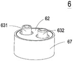
Fig. 6A is a front view of a valve body of a fluid delivery device of an electronic cigarette according to a preferred embodiment of the present invention.
Fig. 6B is a schematic bottom view of the valve body of the fluid delivery device of the electronic cigarette according to the preferred embodiment of the present invention.
Fig. 7A is a front view of a valve chamber seat of a fluid delivery device of an electronic cigarette according to a preferred embodiment of the present invention.
Fig. 7B is a schematic bottom view of a valve chamber of a fluid delivery device of an electronic cigarette according to a preferred embodiment of the present invention.
Fig. 8 is a front view of a valve diaphragm of a fluid delivery device of an electronic cigarette according to a preferred embodiment of the present invention.
Fig. 9 is a perspective view of a valve chamber seat of a fluid delivery device of an electronic cigarette according to a preferred embodiment of the present disclosure.
Fig. 10A is a front view of a valve cover of a fluid delivery device of an electronic cigarette according to a preferred embodiment of the present invention.
Fig. 10B is a schematic view of a bottom surface of a valve cover of the fluid delivery device of the electronic cigarette according to the preferred embodiment of the present invention.
Fig. 11 is a schematic cross-sectional view of a fluid delivery device of an electronic cigarette according to a preferred embodiment of the present invention.
Fig. 12A is a schematic diagram of a fluid-conveying operation state of the fluid-conveying device of the electronic cigarette according to the preferred embodiment of the present invention 1.
Fig. 12B is a schematic diagram of a fluid-conveying operation state of the fluid-conveying device of the electronic cigarette according to the preferred embodiment of the present invention 2.
[ detailed description ] embodiments
Exemplary embodiments that embody features and advantages of this disclosure are described in detail below in the detailed description. It will be understood that the present disclosure is capable of various modifications without departing from the scope of the disclosure, and that the description and drawings are to be regarded as illustrative in nature, and not as restrictive.
Referring to fig. 2A, fig. 2B, fig. 2C, fig. 3A, fig. 3B and fig. 3C, the electronic cigarette according to the preferred embodiment of the present invention includes a housing 1, a driving module 2, a sensor 3, an atomizing component 4, a liquid storage component 5, a fluid delivery device 6, a bracket 7 and a suction nozzle 9. The housing 1 of the present embodiment is assembled by butting the first housing 1a and the second housing 1 b. The battery 23 of the driving module 2 is disposed in the first housing 1a, in this embodiment, the driving module 2 includes a connection interface 20, a power board 21, a control board 22 and a battery 23, the connection interface 20, the power board 21 and the control board 22 are disposed in the second housing 1b, and the power board 21 and the control board 22 are correspondingly disposed on the connection interface 20, so that the power board 21 and the control board 22 are electrically connected to the battery 23 of the driving module 2 through the connection interface 20 of the driving module 2 and are assembled with the first housing 1a and the second housing 1b through the connection interface 20, the second housing 1b further includes an airflow chamber 1d, and the sensor 3, the atomizing part 4, the liquid storage part 5, the fluid delivery device 6 and the bracket 7 are mounted in the second housing 1 b.
In this embodiment, the first casing 1a and the second casing 1b can be, but not limited to, a thin-walled metal tube, such as: stainless steel, having a length and diameter similar to a conventional tobacco cigarette. In the embodiment, at least one air inlet 1c is disposed on the surface of the second housing and disposed adjacent to the fluid transmission device 6, so that the external air can enter from the at least one air inlet 1c and then pass through the airflow chamber 1d of the second housing 1b, the sensor 3 and the suction nozzle 9, thereby forming an airflow loop. In some other embodiments, the at least one air inlet 1c may also be disposed at any position that can be communicated with the airflow chamber 1d, and the at least one air inlet 1c, the airflow chamber 1d, the sensor 3 and the suction nozzle 9 form the airflow loop, so that the atomized smoke can be guided out of the second housing 1b through the airflow chamber 1d, the sensor 3 and the suction nozzle 9 in sequence for the user to suck, but not limited thereto.
In this embodiment, the suction nozzle 9 closes one end of the second housing 1b, the sensor 3 is disposed in the second housing 1b and is adjacent to and communicated with the suction nozzle 9, the sensor 3 is used for sensing air flow and controlling the on/off of the driving power supply of the electronic cigarette; the atomizing member 4 is disposed in the second housing 1b in a manner perpendicular to the inner wall of the second housing 1b, and is disposed adjacent to the sensor 3.
In this embodiment, the atomizing member 4 is disposed in the second housing 1b in a manner perpendicular to the inner wall of the second housing 1b, and disposed adjacent to the sensor 3, and includes an electric heater 41 and a liquid guiding tube 44, the electric heater 41 is a hollow structure, two leads of the electric heater 41 are connected (not shown) to the driving module 2 through a connection interface 20 to realize electric connection, and control the electric heater 41 to start heating or stop heating according to the flow condition detected by the sensor 3, the liquid guiding tube 44 is a liquid conducting tube member, which can be a stainless steel tube member or a heat-resistant tube member, the front end of the liquid guiding tube 44 has an input port 441, a plurality of through holes 442 are disposed on the tube wall of the liquid guiding tube 44, and the electric heater 41 is sleeved on the periphery of the liquid guiding tube 44 to atomize the cigarette liquid to generate an atomized smoke for the user to eat. In this embodiment, the oil inlet pipe 6c is a high temperature resistant flexible pipe, but not limited thereto, the support 7 inside the airflow chamber 1d can be avoided by the arrangement of the oil inlet pipe 6c to be directly communicated to the atomizing component 4, and the flexible pipe has high degree of freedom, so that the disassembly, assembly and maintenance can be facilitated, and the flexibility of the maintenance of the whole internal elements can be improved.
In this embodiment, the bracket 7 is also disposed in the second casing 1b and connected to the inner wall of the second casing 1b, and the bracket 7 includes two protruding portions 71, the two protruding portions 71 are used for fixing and supporting the atomizing component 4 thereon and connected to the atomizing component 4 for providing a supporting force to the atomizing component 4, but not limited thereto, and may be changed according to actual situations. The two protrusions 71 of the bracket 7 support the atomization component 4, so that the contact area with the atomization component 4 can be reduced, and the distribution area of the electric heater 41 sleeved on the periphery of the liquid guide tube 44 is larger, thereby improving the efficiency of heating atomization.
In this embodiment, the liquid storage part 5 is disposed in the second housing 1b for storing the cigarette liquid. The fluid delivery device 6 is also disposed in the second housing 1b and disposed at the bottom of the liquid storage part 5, the fluid delivery device 6 has an input channel 6a, an output channel 6b and an oil inlet pipe 6c, the input channel 6a is communicated with the liquid storage part 5, the output channel 6b penetrates the liquid storage part 5 and is communicated to the input port 441 of the liquid guide tube 44 of the atomizing part 4 through the oil inlet pipe 6c, which is not limited thereto, wherein the fluid delivery device 6 is used as a valve switch to deliver the cigarette liquid inside the liquid storage part 5, and the fluid delivery device 6 is supported and positioned by a support seat 1e and mounted in the second housing 1 b.
In this embodiment, the power board 21 of the driving module 2 includes a voltage converter 211, a heater module 212 and a voltage controller 213, wherein the voltage converter 211 is used for adjusting the voltage of the outputted driving power, the heater module 212 is used for driving the electric heater 41 of the atomizing component 4 to heat and atomize the cigarette liquid, and the voltage controller 213 is used for calculating a specific voltage value.
In this embodiment, the control board 22 further comprises a microprocessor 222 and a fluid transmission driver 221, the microprocessor 222 is used for receiving a control signal and transmitting a driving signal, and the fluid transmission driver 221 is used for providing the driving signal to the fluid transmission device 6 for transmitting the cigarette liquid (as shown in fig. 2A). In this embodiment, when the microprocessor 222 receives the control signal, the microprocessor 222 controls the voltage controller 213 to calculate the specific voltage value according to the control signal, the voltage converter 211 modulates the voltage of the driving power provided by the battery 23 into the specific voltage value through the connection interface 20, and the microprocessor 222 sends the driving signal to the fluid transmission driver 221 and the heater module 212, so that the fluid transmission driver 221 and the heater module 212 respectively provide the driving power with the specific voltage value to the fluid transmission device 6 and the electric heater 41 of the atomization component 4, and the fluid transmission driver 221 is used to provide the driving signal to the fluid transmission device 6 so as to enable the transmission of the cigarette liquid to the electric heater 41 of the atomization component 4 to atomize the cigarette liquid, thereby implementing the transmission and atomization of the cigarette liquid. Therefore, the electronic cigarette of the present embodiment can be electrically connected to the batteries 23 with different voltages by the design of the power supply board 21 of the driving module 2 and the driving module of the control board 22 with adjustable power supply. In addition, through the design of the power supply board 21 of the driving module 2 and the driving module of the adjustable power supply of the control board 22, the specific voltage value is adjusted according to the strength of the airflow generated by the user sucking the atomized smoke, and the voltage change of the driving power supply changes the driving power of the fluid transmission device 6 and the electric heater 41, and the transmission rate of the fluid transmission device 6 and the heating and atomizing rate of the electric heater 41, so that the concentration of the atomized smoke in each mouth is the same in the process of sucking the atomized smoke by the user, and the atomized smoke in each mouth cannot change due to the strength of the sucking force or the high or low sucking speed, thereby achieving the best sucking taste of the electronic cigarette.
In the present embodiment, the battery 23 of the driving module 2 may be, but is not limited to, a rechargeable battery. In some embodiments, the battery 23 of the driving module 2 may also be a disposable battery. In this embodiment, the first housing 1a is also used to detachably configure the battery 23 of the driving module 2, so as to facilitate the portable operation of the whole electronic cigarette device, if the power of the battery 23 is partially insufficient, only the battery 23 with insufficient power of the driving module 2 needs to be replaced, and another new set of batteries 23 (or fully charged batteries 23) needs to be installed and replaced, and the first housing 1a and the second housing 1b are fixedly assembled through the connection interface 20, so that the electronic cigarette device can be re-configured to be portable and electrically connected to operate.
In this embodiment, the sensor 3 further includes an airflow sensor 31 and an air pressure sensor 32. The air flow sensor 31 can provide a control signal to the driving module 2 according to the pressure or speed of the passing air flow to turn on or off the driving power of the driving module 2, the air pressure sensor 32 can change the atomization speed of the tobacco tar and the liquid supply speed according to the monitored pressure of the passing air flow, that is, the pressure of the passing air flow can be monitored according to the suction pressure of a user, the control signal is adjusted to adjust the control signal of the driving module 2, the driving frequency of the fluid delivery device 6 is adjusted to adjust the supply rate of the tobacco tar liquid, and the power of the driving power of the atomizing component 4 is adjusted to adjust the atomization rate of the tobacco tar liquid.
In this embodiment, when the sensor 3 senses the airflow, the sensor 3 sends a control signal to the driving module 2 according to the sensed airflow pressure, so that the driving module 2 controls the fluid delivery device 6 to start to operate according to the control signal, the cigarette liquid in the liquid storage component 5 is guided out from the input channel 6a, delivered to the liquid guide tube 44 of the atomizing component 4 through the output channel 6b and the oil inlet tube 6c, and permeates to the outside of the liquid guide tube 44 through the plurality of through holes 442, so as to control the cigarette liquid to be quantitatively delivered to the electric heater 41 of the atomizing component 4, and heated by the electric heater 41 to generate atomized smoke, and finally, the opening 92 of the suction nozzle 9 is used for the user to suck, and when the user sucks the cigarette by using the at least one air inlet 1c, the air is guided into the airflow loop, thereby balancing the pressure inside and outside the housing 1. On the contrary, when the sensor 3 senses that the air flow stops, the sensor 3 stops sending the control signal to the driving module 2, so that the fluid delivery device 6 stops delivering the cigarette liquid, and the electronic cigarette stops operating. Therefore, by quantitatively delivering the cigarette liquid to the atomization component 4 for atomization, a user can quickly inhale a large amount of atomized smoke, and simultaneously keep the amount and concentration of the atomized smoke in each mouth the same, so as to improve the optimal smoking taste of the electronic cigarette.
The present embodiment further includes a light emitting diode 1f disposed at the front end of the first housing 1a, which can receive the driving power outputted by the battery 23 of the driving module 2, and is controlled by the control board 22 to emit light or extinguish for warning the operation message of the electronic cigarette, and the control board 22 can control the light generated by the light emitting diode 24 with different intensities, so as to provide the prompting function for the smoker to draw the flow intensity of the smoke stream, but not limited thereto.
Referring to fig. 2A, as shown in the figure, the suction nozzle 9 is assembled at one end of the second housing 1b and is communicated with the airflow chamber 1d, and the suction nozzle 9 has a filter cotton 91 and an opening 92, the filter cotton 91 is placed and sealed at one end of the second housing 1b to seal the connection port between the suction nozzle 9 and the second housing 1b, so that the cigarette liquid which is not completely atomized by the initial heating can be blocked by the filter cotton 91 to form a filtering protection measure for preventing inhalation.
With continued reference to fig. 4, 5A, 5B, 6A, 6B, 7A and 7B, the valve body 63 and the valve chamber seat 65 are the main structures for guiding the fluid to enter and exit in the fluid conveying device 6 of the present invention. The valve body 63 has an inlet channel 631 and an outlet channel 632 respectively passing through the first surface 633 and the second surface 634, the inlet channel 631 communicates with an inlet opening 6311 on the second surface 634, the second surface 634 has a groove 6341 surrounding the inlet opening 6311, and has a protrusion 6343 protruding around the inlet opening 6311, the outlet channel 632 communicates with an outlet opening 6321 on the second surface 634, the second surface 634 has a groove 6342 surrounding the outlet opening 6321, and a plurality of mortise slots 63b are disposed on the second surface 634 of the valve body 63.
The valve cavity seat 65 is provided with a plurality of tenons 65a on the third surface 655, which can be correspondingly sleeved in the mortise 63b of the valve body 63, so that the valve body 63 and the valve cavity seat 65 can be combined with each other and stacked for positioning. The valve cavity seat 65 has an inlet valve channel 651 and an outlet valve channel 652 extending through the third surface 655 to the fourth surface 656, and the third surface 655 has a groove 653 surrounding the inlet valve channel 651, and the third surface 655 has a protrusion 6521 protruding around the outlet valve channel 652, and has a groove 654 surrounding the outlet valve channel 652, and further, a pressure chamber 657 is recessed in the fourth surface 656 to communicate with the inlet valve channel 651 and the outlet valve channel 652, respectively, and the fourth surface 656 has a stepped groove 658 outside the pressure chamber 657.
Referring to fig. 5A, 5B and 8, when the main material of the valve diaphragm 64 is Polyimide (PI) polymer, the manufacturing method mainly uses Reactive Ion Etching (RIE) to coat the photosensitive photoresist on the valve structure, expose and develop the valve structure pattern, and then perform etching, so that the valve structure on the valve diaphragm 64 can be etched because the Polyimide (PI) sheet is protected from etching by the photoresist covering portion. Valve membrane 64 is a flat sheet structure. As shown in fig. 8, two valve plates 641a, 641b having the same thickness are respectively retained in the two through regions 64a, 64b of the valve diaphragm 64, and a plurality of extension brackets 642a, 642b are respectively disposed around the periphery of the valve plates 641a, 641b for elastic support, and a hollow hole 643a, 643b is respectively formed between adjacent extension brackets 642a, 642b, so that a valve plate 641a, 641b having the same thickness can be elastically supported by the extension brackets 642a, 642b to be protruded and deformed by a displacement amount to form a valve switch structure. The valve sheets 641a, 641b may be circular, rectangular, square, or various geometric patterns, but not limited thereto. Furthermore, the valve membrane 64 is provided with a plurality of positioning holes 64c, which can be inserted into the tenons 65a of the valve cavity seat 65 on the third surface 655, so that the positioning valve membrane 64 is supported on the valve cavity seat 65, and the valve sheets 641a and 641b respectively cover the inlet valve passage 651 and the outlet valve passage 652 (as shown in fig. 8) of the valve cavity seat 65, in this embodiment, the number of the tenons 65a is 2, and therefore, the number of the positioning holes 64c is 2, but not limited thereto, and can be set according to the number of the tenons 65 a.
Referring to fig. 11, when the valve body 63 and the valve chamber seat 65 are combined and stacked, the grooves 6341, 6342 of the valve body 63 are respectively sleeved with a sealing ring 68a, 68b, the grooves 653, 654 of the valve chamber seat 65 are respectively sleeved with a sealing ring 68c, 68d, the valve body 63 and the valve chamber seat 65 are combined and stacked, the sealing rings 68a, 68b, 68c, 68d can be used to prevent fluid leakage around the valve body, so that the inlet channel 631 of the valve body 63 corresponds to the inlet valve channel 651 of the valve chamber seat 65, the opening/closing inlet channel 631 of the valve plate 641a of the valve diaphragm 64 and the inlet valve channel 651 are communicated, the outlet channel 632 of the valve body 63 corresponds to the outlet valve channel 652 of the valve chamber seat 65, the opening/closing outlet channel 632 of the valve plate 64 and the outlet valve channel 652 are communicated, and when the valve plate 641a of the valve diaphragm 64 is opened, the inlet channel 631 introduces fluid through the inlet valve channel 651 to the pressure chamber 657, and when the valve disc 641b of the valve diaphragm 64 is opened, the fluid in the pressure chamber 657 is discharged through the outlet valve channel 652 to the outside through the outlet channel 632.
Referring to fig. 5A and 5B, the actuator 66 is assembled by a vibrating plate 661 and a piezoelectric element 662, wherein the piezoelectric element 662 is attached and fixed on a surface of the vibrating plate 661. In the present embodiment, the vibrating plate 661 is made of metal, and the piezoelectric element 662 is made of piezoelectric powder of lead zirconate titanate (PZT) series with high piezoelectric number, and is attached to the vibrating plate 661, so that the piezoelectric element 662 is driven to deform by applying a voltage, and the vibrating plate 661 is driven to vibrate and deform in a vertical reciprocating manner along with the applied voltage, so as to drive the fluid conveying device 6 to operate. The vibrating plate 661 of the actuator 66 is assembled on the fourth surface 656 of the valve cavity seat 65 to cover the pressure chamber 657, and the fourth surface 656 is provided with a stepped groove 658 outside the pressure chamber 657 for receiving a sealing ring 68e therein to prevent fluid leakage around the pressure chamber 657.
As is apparent from the above description, the valve body 63, the valve diaphragm 64, the valve chamber seat 65, and the actuator 66 constitute the main structure of the fluid transport device 6 for guiding the transport fluid in and out. In order to position the stacked structure without using locking elements (such as screws, nuts, bolts, etc.) to lock, position and assemble, in the preferred embodiment of the present invention, the valve cover 62 and the outer cylinder 67 are designed, the valve body 63, the valve diaphragm 64, the valve chamber seat 65, and the actuator 66 are sequentially stacked inside the outer cylinder 67, and the valve cover 62 is directly tightly fitted inside the outer cylinder 67 to position and assemble, thereby forming the fluid delivery device 6 of the present invention.
Referring to fig. 5A, 5B and 9, the outer tube 67 is made of metal, and has an inner wall 671 surrounding a hollow space, and a bottom of the inner wall 671 of the outer tube 67 has a protruding ring structure 672. Referring to fig. 10A and 10B, the valve cover 62 is also made of a metal material, and has a first through hole 621 and a second through hole 622 that are respectively inserted into the inlet channel 631 and the outlet channel 632 of the valve body 63, and the bottom edge of the valve cover 62 has a chamfer 623, and the outer diameter of the valve cover 62 is slightly larger than the inner wall 671 of the outer tube 67.
Thus, referring to fig. 5A and 5B, the valve body 63, the valve diaphragm 64, the valve chamber seat 65, and the actuator 66 are sequentially stacked and then placed in the inner wall 671 of the outer tube 67, the entire laminated structure is carried on the collar structure 672 of the outer tube 67, so that the valve cover 62 can be smoothly guided into the inner wall 671 of the outer tube 67 by the chamfer 623 due to the design that the outer diameter is slightly larger than the inner wall 671 of the outer tube 67, the positioning valve body 63, the valve diaphragm 64, the valve cavity seat 65 and the actuator 66 are assembled and combined in a tight fit manner to form the fluid conveying device 6 in a stacking manner, the actuator 66 can also be located in the hollow space of the inner wall 671 of the outer tube 67, and the piezoelectric element 662 is applied with voltage to drive the vibrating plate 661 to reciprocate vertically to generate deformation resonance, so as to achieve the purpose of locking and positioning the assembled fluid delivery device 6 without using a locking element (such as a screw, a nut, a bolt, etc.).
As shown in fig. 11, in the fluid delivery device 6 of the present invention, the inlet valve passage 651 of the valve chamber seat 65 is disposed corresponding to the inlet opening 6311 of the valve body 63, and the valve piece 641a of the valve diaphragm 64 is used to seal the inlet opening 6311 of the valve body 63, and the valve piece 641a is used to cover the inlet opening 6311 of the valve body 63, and the convex portion structure 6343 of the valve body 63 is used to generate a preload (preload) effect, which is helpful to generate a greater preload effect to prevent the reverse flow, while the outlet valve passage 652 is disposed corresponding to the outlet opening 6321 of the valve body 63, and the valve piece 641b of the valve diaphragm 64 is used to seal the outlet valve passage 652 of the valve chamber seat 65, and the convex portion structure 6521 of the valve chamber seat 65 is used to generate a preload (preload) effect, which is helpful to generate a greater preload effect, the fluid delivery device 6 is constructed so that no backflow occurs between the inlet channel 631 and the outlet channel 632 of the valve body 63 when the fluid delivery device is not actuated by preventing the backflow of the pressure chamber 657.
As can be seen from the above description, the fluid delivery device 6 of the present embodiment performs the fluid transfer operation, as shown in fig. 12A, when the piezoelectric element 662 of the actuator 66 is actuated by the applied voltage to deform the vibration plate 661 concavely, the volume of the pressure chamber 657 increases, thereby generating a suction force to rapidly open the valve plate 641a of the valve diaphragm 64 by a suction force, so that a large amount of fluid can be sucked from the inlet channel 631 of the valve body 63, and flows through the inlet opening 6311 of the valve body 63, through the through-hole 643a of the valve diaphragm 64 (not labeled in fig. 12A, see fig. 8), through the inlet valve passage 651 of the valve chamber seat 65 to the pressure chamber 657 for temporary storage, at the same time, the outlet valve channel 652 is also exposed to a suction force, and the valve plate 641b of the valve membrane 64 is supported by the extension 642b to be entirely flush against the boss structure 6521 to assume a closed state.
Thereafter, as shown in fig. 12B, when the direction of the electric field applied to the piezoelectric element 662 is changed, the piezoelectric element 662 deforms the vibrating plate 661 to deform upward, the pressure chamber 657 contracts to reduce the volume, the fluid in the pressure chamber 657 is compressed, the inlet valve channel 651 receives a thrust force at the same time, the valve plate 641a of the valve diaphragm 64 receives the thrust force, the extending support 642a supports the valve plate 64 to be entirely in flat contact with the protrusion structure 6343 to be in a closed state, the fluid cannot flow backward through the inlet valve channel 651, the outlet valve channel 652 also receives the thrust force, the valve plate 641B of the valve diaphragm 64 receives the thrust force, the extending support 642B supports the valve plate to be entirely in a state of being separated from the flat contact with the protrusion structure 6521 to be in an open state, the fluid can flow out of the pressure chamber 657 through the outlet valve channel 652, and then flows through the outlet valve channel 652 of the valve seat 65, The through-hole 643B (not labeled in fig. 12B, see fig. 8) of the valve membrane 64, the outlet opening 6321 of the valve body 63 and the outlet channel 632 exit the fluid delivery device 6, thereby completing the fluid delivery process. The fluid can be continuously transported by repeating the operations shown in fig. 12A and 12B, so that the fluid transporting device 6 of the present invention can achieve efficient transportation without causing backflow during the transportation process.
The fluid delivery device 6 is positioned and installed in the second housing 1b, assembled on the support base 1e, and disposed at the bottom of the liquid storage part 5, the inlet channel 631 of the fluid delivery device 6 communicates with the input channel 6a to the liquid storage part 5, the outlet channel 632 of the fluid delivery device 6 communicates with the output channel 6b and the oil inlet pipe 6c, and the output channel 6b and the oil inlet pipe 6c communicate with the input port 441 of the liquid guide tube 44 of the atomization part 4, so that the cigarette liquid can be delivered to the liquid guide tube 44 by the fluid delivery device 6 and permeate out of the liquid guide tube 44 through the plurality of through holes 442. Therefore, when the fluid delivery device 6 is driven by the voltage control provided by the control board 22, the cigarette liquid can be quantitatively delivered from the liquid storage part 5, and can be used as a switch to control the supply of the cigarette liquid in the liquid storage part 5, so that the cigarette liquid is quantitatively delivered and guided into the liquid guide tube 44, under the same pressure, the cigarette liquid can be uniformly delivered and permeated outside the liquid guide tube 44 through the plurality of through holes 442, so as to generate liquid drop homogenization, and the delivery can be controlled to be closed when the content outside the liquid guide tube 44 is full, so that the fluid delivery device 6 is combined with the arrangement of the atomization part 4 to form a controllable switch to accurately control the amount of the cigarette liquid permeating the atomization part 4, and the problems of uneven smoke taste and poor oil permeation caused by the liquid drops in the known electronic cigarette technology are solved.
As can be seen from the above, the specific implementation of the electronic cigarette of the present invention is described as follows, when the user inhales from the opening 92 of the mouthpiece 9, the air in the electronic cigarette flows, at this time, the sensor 3 turns on the circuit, and the electric heater 41 is started to heat; when the user stops inhaling from the opening 92 of the mouthpiece 9, the flow of air stops and the sensor 3 closes the circuit to stop the electric heater 41 from heating; thus, the fluid delivery device 6 of the present application combines with the atomization component 4 to form a controllable switch to accurately control the amount of the liquid permeating the atomization component 4, the liquid storing component 5 of the cigarette permeates the liquid guide tube 44 quantitatively under the control of the fluid delivery device 6, when the user inhales air through the opening 92 of the suction nozzle 9, the gas in the electronic cigarette flows, the sensor 3 opens the whole circuit according to the airflow, the driving module 2 supplies power to the heating module 23 to start the electric heater 41 to heat, and the liquid permeating the liquid guide tube 44 quantitatively can be controlled, and the liquid is quantitatively delivered to the electric heater 41 to generate atomized smoke, and the atomized smoke is guided out by the suction nozzle 9, so as to provide the user with the smoking. In addition, when the user inhales from the opening 92 of the suction nozzle 9, the air pressure sensor 32 can be used to monitor the pressure of the passing air flow according to the suction pressure of the user, the output signal can be adjusted to adjust the control signal of the control board 22, and the driving frequency of the fluid delivery device 6 and the driving power of the electric heater 41 can be adjusted to change the atomization speed and the liquid supply speed of the cigarette liquid in a fixed amount, so that the user can inhale a large amount of atomized smoke quickly, and can keep the amount and concentration of the atomized smoke in each mouth the same after one mouth.
In summary, the present disclosure provides a driving module for an electronic cigarette, which mainly controls a fluid delivery device to form a controllable switch to accurately control the amount of liquid permeating an atomizing component of the cigarette, and is provided with a sensor, when the sensor senses the air flow, the sensor sends a control signal to the control panel of the driving module according to the air flow pressure, so that the control panel controls the power panel to calculate a specific voltage value according to the control signal, the voltage of the driving power supply provided by the battery through the connection interface is adjusted to the specific voltage value, the control panel drives the fluid delivery device to start to operate, the cigarette liquid in the liquid storage part is led out from the input channel and is delivered into the catheter through the output channel, the liquid permeates out of the liquid guide pipe through a plurality of through holes so as to control the cigarette liquid to be quantitatively conveyed to an electric heater of the atomization component to generate atomized smoke, and the atomized smoke is provided for a user to suck by an opening of the suction nozzle; when the sensor senses that the air flow stops, the sensor stops sending a control signal to the driving module, so that the fluid conveying device stops conveying the cigarette liquid, and the electronic cigarette stops operating. Therefore, the sensor monitors the pressure of the passing air flow, adjusts the output signal to adjust the control signal of the control panel, modulates the driving frequency of the fluid conveying device and the driving power supply power of the heater module to change the atomizing speed and the liquid supply speed of the tobacco tar, and prevents the conveying operation of the fluid conveying device against the reverse flow, so that the high-efficiency transmission can be achieved, and the problems of uneven smoke taste and oil leakage caused by liquid drops in the known electronic cigarette technology are solved. Therefore, the electronic cigarette of the present application has great industrial application value, and the application is proposed according to the law.
Various modifications may be made by those skilled in the art without departing from the scope of the invention as defined by the appended claims.
[ notation ] to show
1: shell body
1 a: first shell
1 b: second shell
1 c: air inlet
1 d: airflow chamber
1 e: supporting seat
1 f: light emitting diode
2: drive module
20: connecting interface
21: power panel
211: voltage converter
212: heater module
213: voltage controller
22: control panel
221: fluid delivery actuator
222: microprocessor
23: battery with a battery cell
3: sensor with a sensor element
31: airflow sensor
32: air pressure sensor
4: atomizing component
41: electric heater
42: fluid permeable member
43: liquid conducting member
431: conducting part
44: liquid guiding tube
441: input port
442: through hole
5: liquid storage member
51: channel
52: liquid storage container
6: fluid delivery device
6 a: input channel
6 b: output channel
6 c: oil inlet pipe
62: valve cover
621: the first through hole
622: second through hole
623: chamfering
63: valve body
631: inlet channel
6311: an inlet opening
632: outlet channel
6321: outlet opening
633: first surface
634: second surface
6341. 6342: groove
6343: convex part structure
63 b: mortise and tenon slot
64: valve diaphragm
64a, 64 b: through region
641a, 641 b: valve plate
642a, 642 b: extension support
643a, 643 b: hollow hole
64 c: locating hole
65: valve cavity seat
651: inlet valve passage
652: outlet valve passage
6521: convex part structure
653. 654: groove
655: third surface
656: the fourth surface
657: pressure chamber
658: segment difference groove
65 a: clamping tenon
66: actuator
661: vibrating plate
662: piezoelectric element
67: outer cylinder
671: inner wall
672: convex ring structure
68a, 68b, 68c, 68d, 68 e: sealing ring
7: support frame
71: projection part
8: electrode ring
9: suction nozzle
91: filter cotton
92: opening holes
10: connecting part
Claims (18)
1. A drive module of electronic cigarette is suitable for an electronic cigarette containing a cigarette liquid, and the electronic cigarette comprises a shell, a suction nozzle, a sensor, an atomization component, a liquid storage component and a fluid conveying device, and is characterized in that the drive module of electronic cigarette comprises:
a battery for providing a driving power supply for the electronic cigarette;
a connection interface electrically connected to the battery;
a power panel electrically connected to the battery through the connection interface and including a voltage converter, a heater module and a voltage controller, wherein the voltage converter is used for modulating the voltage of the battery output driving power, the heater module is used for driving the atomization component to heat and atomize the cigarette liquid, and the voltage controller is used for calculating a specific voltage value; and
the control panel is electrically connected with the battery through the connecting interface and comprises a microprocessor and a fluid transmission driver, wherein the microprocessor is used for receiving a control signal and transmitting a driving signal, and the fluid transmission driver is used for providing the driving signal to the fluid transmission device;
when the microprocessor receives the control signal, the microprocessor controls the voltage controller to calculate the specific voltage value according to the control signal, then the voltage converter modulates the voltage of the driving power supply provided by the battery into the specific voltage value, the microprocessor sends the driving signal to the fluid transmission driver and the heater module, so that the fluid transmission driver and the heater module respectively provide the driving power supply with the specific voltage value for the fluid transmission device and the atomization component, the fluid transmission device and the atomization component are enabled, the fluid transmission device transmits the cigarette liquid to the atomization component, and the atomization component atomizes the cigarette liquid to generate atomized smoke;
the sensor of the electronic cigarette further comprises an airflow sensor and an air pressure sensor, the airflow sensor controls the electronic cigarette to be turned on or turned off according to the passing airflow, and the air pressure sensor changes and adjusts the output control signal according to the monitored passing airflow pressure so as to adjust the driving frequency of the fluid conveying device and the driving power of the heater module and change the liquid supply speed of the fluid conveying device and the speed of the atomizing component for atomizing the cigarette liquid.
2. The driving module of claim 1, wherein the housing of the electronic cigarette is assembled by a first housing and a second housing, wherein the first housing is internally installed with the battery, the second housing is internally installed with the sensor, the liquid storage component, the fluid delivery device, the atomizing component, the connection interface, the power board and the control board, and the first housing and the second housing are assembled and electrically connected through the connection interface.
3. The driving module of claim 1, wherein the electronic cigarette further comprises a bracket disposed in the housing and connected to an inner wall of the housing for providing a supporting force to the atomizing member.
4. The drive module of the electronic cigarette of claim 1, wherein the battery of the drive module of the electronic cigarette is a disposable battery.
5. The drive module of the electronic cigarette of claim 1, wherein the battery of the drive module of the electronic cigarette is a rechargeable battery.
6. The driving module of an electronic cigarette of claim 1, wherein the electronic cigarette further comprises a light emitting diode.
7. The driving module of claim 6, wherein the light emitting diode of the electronic cigarette is disposed at one end of the housing and controlled by the control board to emit light or extinguish for providing an operation message alarm.
8. The driving module of claim 6, wherein the light emitting diode of the electronic cigarette is disposed at one end of the housing and controlled by the control board to adjust the brightness of the light emitting diode to provide a prompt for smoking the intensity of the atomized smoke.
9. The driving module of an electronic cigarette as in claim 1, wherein the atomizing member comprises an electric heater and a liquid guide tube, the liquid guide tube being a stainless material member.
10. The driving module of the electronic cigarette according to claim 1, wherein the atomizing part of the electronic cigarette comprises an electric heater and a liquid guide tube, the liquid guide tube being a heat-resistant tube part.
11. The driving module of claim 1, wherein the suction nozzle of the electronic cigarette includes a filter cotton therein, and the filter cotton seals the connection port between the suction nozzle and the housing, so that the cigarette liquid which is not completely atomized by heating is blocked by the filter cotton to form a filtering protection measure against inhalation.
12. The drive module of an electronic cigarette of claim 1 wherein the fluid transport device further comprises:
the valve body is provided with an inlet channel, an outlet channel, a first surface and a second surface, the inlet channel and the outlet channel are arranged between the first surface and the second surface in a penetrating mode, the inlet channel is communicated with an inlet opening on the second surface, and the outlet channel is communicated with an outlet opening on the second surface;
the valve diaphragm is provided with two valve plates with the same thickness, a plurality of extension supports are respectively arranged around the peripheries of the two valve plates for elastic support, and a hollow hole is respectively formed between every two adjacent extension supports;
the valve cavity seat is provided with a third surface, a fourth surface, an inlet valve channel and an outlet valve channel, the inlet valve channel and the outlet valve channel are arranged between the third surface and the fourth surface in a penetrating mode, the two valve sheets of the valve membrane are respectively borne on the inlet valve channel and the outlet valve channel to form valve structures, and a pressure chamber is recessed on the fourth surface and is respectively communicated with the inlet valve channel and the outlet valve channel;
an actuator covering the pressure chamber of the valve cavity seat;
the valve body, the valve diaphragm, the valve cavity seat and the actuator are assembled in sequence respectively, the actuator drives and controls the inlet channel to suck the cigarette liquid, and the outlet channel outputs the cigarette liquid.
13. The electronic cigarette driving module of claim 12, wherein the second surface of the valve body of the fluid delivery device is provided with a plurality of mortise slots, and the third surface of the valve cavity seat is provided with a plurality of tenons for being correspondingly sleeved in the mortise slots to position the valve cavity seat assembly on the valve body.
14. The electronic cigarette driving module of claim 13, wherein the valve membrane of the fluid transfer device is disposed between the valve body and the valve cavity seat, and a plurality of positioning holes are disposed at positions corresponding to the plurality of tenons of the valve cavity seat, respectively, for penetrating into the plurality of tenons to position the valve membrane.
15. The driving module of an electronic cigarette according to claim 12, wherein the second surface of the valve body of the fluid delivery device has a plurality of grooves surrounding the inlet opening and the outlet opening, respectively, and the valve chamber seat has a plurality of grooves surrounding the inlet valve passage and the outlet valve passage, respectively, on the third surface, the plurality of grooves being for a sealing ring to be fitted therein, respectively, for preventing fluid leakage to the periphery.
16. The electronic cigarette driving module of claim 12, wherein the valve body of the fluid delivery device has a protrusion on the second surface surrounding the inlet opening protrusion, and the valve chamber seat has a protrusion on the third surface surrounding the outlet valve passage protrusion, the two protrusions respectively urging the two valve flaps of the valve membrane into engagement to facilitate pre-capping against reverse flow and generate a pre-stressing force.
17. The driving module of claim 12, wherein the actuator of the fluid delivery device is assembled by a vibrating plate and a piezoelectric element, wherein the piezoelectric element is attached to a surface of the vibrating plate for applying a voltage to drive the piezoelectric element to deform, and the vibrating plate of the actuator is disposed on the fourth surface of the valve cavity seat to cover the pressure chamber.
18. The drive module of an electronic cigarette of claim 12 wherein the fluid transport device further comprises:
a valve cover body which is provided with a first through hole and a second through hole; and
an outer cylinder having an inner wall surrounding a hollow space, and a convex ring structure at the bottom of the inner wall, so that the valve body, the valve membrane, the valve chamber seat and the actuator are stacked in the hollow space in sequence and supported on the convex ring structure, and the first through hole and the second through hole of the valve cover are sleeved into the inlet channel and the outlet channel of the valve body respectively.
Priority Applications (1)
| Application Number | Priority Date | Filing Date | Title |
|---|---|---|---|
| CN201710446914.4A CN109123792B (en) | 2017-06-14 | 2017-06-14 | Driving module of electronic cigarette |
Applications Claiming Priority (1)
| Application Number | Priority Date | Filing Date | Title |
|---|---|---|---|
| CN201710446914.4A CN109123792B (en) | 2017-06-14 | 2017-06-14 | Driving module of electronic cigarette |
Publications (2)
| Publication Number | Publication Date |
|---|---|
| CN109123792A CN109123792A (en) | 2019-01-04 |
| CN109123792B true CN109123792B (en) | 2021-08-06 |
Family
ID=64829906
Family Applications (1)
| Application Number | Title | Priority Date | Filing Date |
|---|---|---|---|
| CN201710446914.4A Active CN109123792B (en) | 2017-06-14 | 2017-06-14 | Driving module of electronic cigarette |
Country Status (1)
| Country | Link |
|---|---|
| CN (1) | CN109123792B (en) |
Families Citing this family (4)
| Publication number | Priority date | Publication date | Assignee | Title |
|---|---|---|---|---|
| CN109924548A (en) * | 2019-04-04 | 2019-06-25 | 惠州市新泓威科技有限公司 | The atomising device and its control method of controllable intake dosage |
| CN110173885B (en) * | 2019-04-18 | 2023-10-27 | 深圳市天士力神通本草技术开发有限公司 | Atomizer and heating structure of atomizer |
| CN111642819A (en) * | 2020-06-30 | 2020-09-11 | 英华达(上海)科技有限公司 | Electronic cigarette with filtering function |
| CN113397223A (en) * | 2021-06-30 | 2021-09-17 | 深圳市艾溹技术研究有限公司 | Electronic atomization device and atomization assembly thereof |
Citations (3)
| Publication number | Priority date | Publication date | Assignee | Title |
|---|---|---|---|---|
| CN101581291A (en) * | 2008-05-16 | 2009-11-18 | 研能科技股份有限公司 | Fluid conveying device |
| CN105962417A (en) * | 2015-03-13 | 2016-09-28 | 方特慕控股第私人有限公司 | Aerosol generating component for an electronic smoking device, electronic smoking device and method for generating an inhalant |
| WO2017037457A1 (en) * | 2015-09-01 | 2017-03-09 | Beyond Twenty Limited | Electronic vaporiser system |
Family Cites Families (3)
| Publication number | Priority date | Publication date | Assignee | Title |
|---|---|---|---|---|
| CN205196989U (en) * | 2013-06-26 | 2016-05-04 | 吉瑞高新科技股份有限公司 | Electronic cigarette |
| WO2016118645A1 (en) * | 2015-01-22 | 2016-07-28 | Fontem Holdings 1 B.V. | Electronic vaporization devices |
| CN207167763U (en) * | 2017-06-14 | 2018-04-03 | 研能科技股份有限公司 | The drive module of electronic cigarette |
-
2017
- 2017-06-14 CN CN201710446914.4A patent/CN109123792B/en active Active
Patent Citations (3)
| Publication number | Priority date | Publication date | Assignee | Title |
|---|---|---|---|---|
| CN101581291A (en) * | 2008-05-16 | 2009-11-18 | 研能科技股份有限公司 | Fluid conveying device |
| CN105962417A (en) * | 2015-03-13 | 2016-09-28 | 方特慕控股第私人有限公司 | Aerosol generating component for an electronic smoking device, electronic smoking device and method for generating an inhalant |
| WO2017037457A1 (en) * | 2015-09-01 | 2017-03-09 | Beyond Twenty Limited | Electronic vaporiser system |
Also Published As
| Publication number | Publication date |
|---|---|
| CN109123792A (en) | 2019-01-04 |
Similar Documents
| Publication | Publication Date | Title |
|---|---|---|
| TWI644626B (en) | Driving module of electronic cigarette | |
| TWI642369B (en) | Electronic cigarette | |
| TWI653944B (en) | Electronic cigarette | |
| CN109123792B (en) | Driving module of electronic cigarette | |
| TWI644625B (en) | Electronic cigarette | |
| TWI640257B (en) | Electronic cigarette | |
| TWI640256B (en) | Electronic cigarette | |
| TWI631910B (en) | Electronic cigarette | |
| CN108968151B (en) | Electronic cigarette | |
| CN108685183B (en) | Electronic cigarette | |
| TWI625099B (en) | Electronic cigarette | |
| CN108685180B (en) | Electronic cigarette | |
| CN108685181B (en) | Electronic cigarette | |
| TWM547850U (en) | Electronic cigarette | |
| TWI640255B (en) | Electronic cigarette | |
| CN108685178B (en) | Electronic cigarette | |
| TWM544801U (en) | Electronic cigarette | |
| CN210130351U (en) | Electronic cigarette | |
| TW201836493A (en) | Electronic cigarette | |
| TWM548451U (en) | Driving module of electronic cigarette | |
| CN108685177B (en) | Electronic cigarette | |
| TWM546115U (en) | Electronic cigarette | |
| CN210130352U (en) | Electronic cigarette | |
| CN210901391U (en) | Electronic cigarette | |
| CN108685182B (en) | Electronic cigarette |
Legal Events
| Date | Code | Title | Description |
|---|---|---|---|
| PB01 | Publication | ||
| PB01 | Publication | ||
| SE01 | Entry into force of request for substantive examination | ||
| SE01 | Entry into force of request for substantive examination | ||
| GR01 | Patent grant | ||
| GR01 | Patent grant |