CN109108552B - Welding tool for output cam of spring operating mechanism and using method of welding tool - Google Patents
Welding tool for output cam of spring operating mechanism and using method of welding tool Download PDFInfo
- Publication number
- CN109108552B CN109108552B CN201811141187.1A CN201811141187A CN109108552B CN 109108552 B CN109108552 B CN 109108552B CN 201811141187 A CN201811141187 A CN 201811141187A CN 109108552 B CN109108552 B CN 109108552B
- Authority
- CN
- China
- Prior art keywords
- support
- welding
- cam
- workpiece
- hole
- Prior art date
- Legal status (The legal status is an assumption and is not a legal conclusion. Google has not performed a legal analysis and makes no representation as to the accuracy of the status listed.)
- Active
Links
- 238000003466 welding Methods 0.000 title claims abstract description 74
- 238000000034 method Methods 0.000 title claims abstract description 11
- 238000003825 pressing Methods 0.000 claims abstract description 47
- 230000005540 biological transmission Effects 0.000 claims description 24
- 238000005056 compaction Methods 0.000 description 2
- 230000007547 defect Effects 0.000 description 2
- 238000004519 manufacturing process Methods 0.000 description 2
- 238000012986 modification Methods 0.000 description 2
- 230000004048 modification Effects 0.000 description 2
- 230000009286 beneficial effect Effects 0.000 description 1
- 238000005266 casting Methods 0.000 description 1
Images


Classifications
-
- B—PERFORMING OPERATIONS; TRANSPORTING
- B23—MACHINE TOOLS; METAL-WORKING NOT OTHERWISE PROVIDED FOR
- B23K—SOLDERING OR UNSOLDERING; WELDING; CLADDING OR PLATING BY SOLDERING OR WELDING; CUTTING BY APPLYING HEAT LOCALLY, e.g. FLAME CUTTING; WORKING BY LASER BEAM
- B23K37/00—Auxiliary devices or processes, not specially adapted for a procedure covered by only one of the other main groups of this subclass
- B23K37/04—Auxiliary devices or processes, not specially adapted for a procedure covered by only one of the other main groups of this subclass for holding or positioning work
- B23K37/0426—Fixtures for other work
- B23K37/0435—Clamps
- B23K37/0443—Jigs
-
- Y—GENERAL TAGGING OF NEW TECHNOLOGICAL DEVELOPMENTS; GENERAL TAGGING OF CROSS-SECTIONAL TECHNOLOGIES SPANNING OVER SEVERAL SECTIONS OF THE IPC; TECHNICAL SUBJECTS COVERED BY FORMER USPC CROSS-REFERENCE ART COLLECTIONS [XRACs] AND DIGESTS
- Y02—TECHNOLOGIES OR APPLICATIONS FOR MITIGATION OR ADAPTATION AGAINST CLIMATE CHANGE
- Y02P—CLIMATE CHANGE MITIGATION TECHNOLOGIES IN THE PRODUCTION OR PROCESSING OF GOODS
- Y02P70/00—Climate change mitigation technologies in the production process for final industrial or consumer products
- Y02P70/10—Greenhouse gas [GHG] capture, material saving, heat recovery or other energy efficient measures, e.g. motor control, characterised by manufacturing processes, e.g. for rolling metal or metal working
Landscapes
- Physics & Mathematics (AREA)
- Optics & Photonics (AREA)
- Engineering & Computer Science (AREA)
- Mechanical Engineering (AREA)
- Resistance Welding (AREA)
Abstract
The invention discloses a welding fixture for an output cam of a spring operating mechanism and a use method thereof, wherein a fixed hole is formed in the center of a fixed disc, a short support is fixedly arranged at the front and rear parts of the fixed disc respectively, a long support is fixedly arranged at the left part of the fixed disc, an upper inner support is sleeved on the long support, a main support is fixedly arranged at the right part of the fixed disc, a rectangular fixed block is arranged at the middle part of the main support, a sliding hole is formed in the middle part of the fixed block, a lower support is sleeved in the sliding hole, a pressing device is respectively arranged on the short support and the main support, the pressing device comprises a rotating rod and an eccentric wheel, and workpieces to be welded are arranged in the fixed hole of the fixed disc; when the workpiece is used, the workpiece is placed into the fixing hole, the workpiece is limited through the upper support and the lower support respectively, and after the workpiece is compressed through the compressing device, the workpiece is convenient to spot-weld, and the workpiece is convenient to subsequently process; the invention has the advantages of accurate positioning and convenient use.
Description
Technical Field
The invention belongs to the technical field of welding tools, and particularly relates to a welding tool for an output cam of a spring operating mechanism and a use method of the welding tool.
Background
In actual production of the spring operating mechanism, the output cam is used as a main power executing component, so that the mutual position relation among all parts of the output cam needs to be ensured, if the spring operating mechanism cannot normally operate due to the reason of processing and manufacturing the output cam, the time for opening or closing the circuit breaker is changed, and the uncompensated loss is likely to be caused to electric equipment of a user; the existing output cams are usually cast to ensure the precision, but the output cams have the defects of casting, further require subsequent processing, have larger workload during actual processing, have difficult precision to be effectively ensured, and are inconvenient to operate during processing.
In order to solve the above problems, it is necessary to develop a welding fixture for the output cam of the spring operating mechanism, which has accurate positioning and convenient use, and a using method thereof.
Disclosure of Invention
The invention aims to overcome the defects of the prior art and provide an output cam welding tool with a spring operating mechanism and a use method thereof, wherein the output cam welding tool is accurate in positioning and convenient to use.
The purpose of the invention is realized in the following way: in a first aspect, a welding fixture for a cam output mechanism of a spring operation is provided, a fixing groove is formed in the disc surface on the front side and the rear side of a fixing disc, a semicircular fixing hole is formed in the center of the fixing disc, short supports are fixedly arranged on the front side and the rear side of the fixing disc respectively, the short supports are in the form of stepped shafts, a lower supporting surface is arranged on the short supports, a lower pressing hole is formed in the upper portion of each short support, the center of each lower pressing hole is 23-24mm away from the lower supporting surface, a long support is fixedly arranged on the left portion of the fixing disc, the long support comprises a supporting post and a supporting plate, a supporting plate is fixedly arranged on the upper portion of each supporting post in a welding mode, an upper inner supporting sleeve is arranged on the long support, the upper inner supporting sleeve comprises a circular ring and an inner supporting body, the short supports are fixedly arranged together in a welding mode, the circular ring is arranged on the upper portion of each supporting plate, a main supporting plate is fixedly arranged on the right portion of the fixing disc, a rectangular supporting block is fixedly arranged on the center of each lower pressing hole, the distance between the lower supporting plate and the main supporting plate is 23mm, a pressing device is arranged on the lower supporting sleeve is fixedly arranged on the center of the main supporting plate, the main supporting plate is provided with a pressing hole, the upper sliding rod is fixedly arranged on the center of the main supporting plate, the upper supporting plate is provided with a pressing device is arranged at the center of the upper supporting hole, the upper sliding rod is provided with a pressing device, the pressing device is arranged on the center of the upper sliding rod is arranged, and the upper sliding rod is arranged, the upper end is provided with a pressing device is arranged, and the pressing device is arranged. The right-hand member of rotary rod is provided with plum blossom shape and revolves the head, the left end of rotary rod is provided with hexagonal axle section, the cover is equipped with the eccentric wheel on the hexagonal axle section, be provided with the work piece that waits to weld in the fixed orifices of fixed disk, the work piece includes transmission shaft, output cam and welding cam.
Further, the lower supporting surface is a shoulder plane of the short-supported stepped shaft.
Further, the axis of the lower pressing hole is along the front-rear direction of the fixed disk.
Further, the center of the lower pressing hole is spaced from the lower supporting surface by 23.5mm.
Further, the inner support body is provided with a large support ring and a small support ring, under the working state, the large support ring and the transmission shaft are concentric, the small support ring and the main support are concentric, and the height of the inner support body is equal to the distance between two welding cams of the workpiece.
Further, the distance from the center of the upper pressing hole to the upper supporting surface is 22.5mm.
Further, the lower supporting plate is provided with a center ring and a side ring, the center ring and the transmission shaft are concentric in the working state, the side ring and the short support are concentric in the center, and the height of the lower supporting plate is equal to the distance between the two output cams of the workpiece.
Further, the eccentricity of the eccentric is 1.4mm.
Further, the positions of the short support, the main support and the fixing holes are in one-to-one correspondence with the design positions of the workpiece.
In a second aspect, a method for using a welding tool for an output cam of a spring operating mechanism is provided, including the following steps:
(1) Fixing the fixed disc on the welding rotary table through the fixed groove, and placing the transmission shaft of the workpiece into the fixed hole;
(2) After passing through the transmission shaft, the output cams are placed on a lower supporting surface of the short support, the internal space between the upper output cam and the lower output cam is ensured through a lower support arranged in the sliding hole, and the upper output cam is tightly pressed through a pressing device;
(3) After passing through the transmission shaft, the lower welding cam is placed on the upper supporting surface of the main support and the upper surface of the supporting plate, and then the axial and circumferential positioning of the upper welding cam is completed through the inner supporting body and the pressing device;
(4) And performing circumferential spot welding on the upper surface of the upper welding cam, the lower surface of the lower welding cam, the upper surface of the upper output cam and the lower surface of the lower output cam, which are contacted with the transmission shaft, respectively by a welding machine.
Due to the adoption of the technical scheme, the invention has the beneficial effects that:
(1) The relative positions of the transmission shaft, the output cam and the welding cam of the workpiece are ensured through the fixed holes, the short support and the main support, so that the circumferential direction of the workpiece is positioned accurately;
(2) The lower part of the output cam of the workpiece and the lower part of the welding cam are supported through the lower supporting surface, the supporting plate and the upper supporting surface; the distance between the two output cams at the lower part is ensured through the upper inner support; the interval between the two welding cams at the upper part is ensured through the arranged lower support; the upper part of the output cam and the upper part of the welding cam are ensured to be pressed by the pressing device, and meanwhile, the pressing device can move back and forth along the hole in the upper pressing hole or the lower pressing hole, so that the contact position of the pressing device and a workpiece can be conveniently adjusted, the phenomenon that the output cam or the welding cam is tilted due to uneven stress is prevented, and the axial positioning precision of the workpiece in welding positioning is affected;
(3) Through the upper internal stay, the lower support and the pressing device, after spot welding positioning is finished on one workpiece, the workpiece is conveniently taken down from the welding device, and meanwhile, the pressing device adopts the eccentric wheel, and the output cam and the welding cam are pressed in a smaller space, so that the use of a welding gun is not influenced, and the spot welding is more convenient.
Drawings
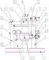
Fig. 1 is a perspective view of the present invention.
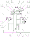
Fig. 2 is a front view of the present invention.
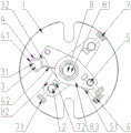
Fig. 3 is a top view of the present invention.
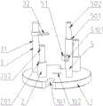
Fig. 4 is a left side view of the present invention.
Fig. 5 is a perspective view of the components 1, 2, 3, 5 of the invention in combination.
Fig. 6 is a perspective view of the component 4 of the present invention.
Fig. 7 is a perspective view of the component 6 of the present invention.
Fig. 8 is a perspective view of the component 7 of the present invention.
Fig. 9 is a perspective view of the component 8 of the present invention.
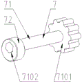
In the figure: 1. the fixed disk 2, the short support 3, the long support 31, the stay 32, the stay plate 4, the upper inner support 41, the circular ring 42, the inner support 5, the main support 51, the fixed block 6, the lower support 61, the slide bar 62, the lower stay plate 63, the rotating wheel 7, the pressing device 71, the rotating rod 72, the eccentric wheel 8, the workpiece 81, the transmission shaft 82, the output cam 83, the welding cam 101, the fixed slot 102, the fixed hole 201, the lower support surface 202, the lower pressing hole 4201, the large support ring 4202, the small support ring 501, the upper support surface 502, the upper pressing hole 5101, the sliding hole 6201, the center ring 6202, the side ring 7101, the quincuncial rotary head 7102, and the hexagonal shaft segment.
Detailed Description
The technical scheme of the invention is further specifically described below through examples and with reference to the accompanying drawings.
As shown in fig. 1 to 9, in a first aspect, there is provided a welding fixture for an output cam of a spring operating mechanism, a fixing groove 101 is provided on a disc surface on both front and rear sides of a fixing disc 1, so that the fixing disc 1 can be fixed on a welding turntable, a semicircular fixing hole 102 is provided in the center of the fixing disc 1, short supports 2 are respectively fixedly provided on the front and rear sides of the fixing disc 1, the short supports 2 are in the form of stepped shafts, a lower support surface 201 is provided on the short supports 2, the lower support surface 201 is a shoulder plane of the stepped shaft of the short supports 2, a distance from the lowermost output cam 82 to the bottom surface of a transmission shaft 81 is ensured by the provided lower support surface 201, a distance from the center of the lower pressing hole 202 to the lower support surface 201 is 23-24mm, and here, preferably 23.5mm is ensured.
As shown in fig. 1-9, the left part of the fixing disc 1 is fixedly provided with a long support 3, the long support 3 comprises a support column 31 and a support plate 32, the upper part of the support column 31 is fixedly provided with the support plate 32 in a welding manner, the long support 3 is sleeved with an upper inner support 4, the upper inner support 4 comprises a circular ring 41 and an inner support 42, the circular ring 41 and the inner support 42 are fixed together in a welding manner, the circular ring 41 is sleeved on the long support 3, the circular ring 41 is positioned on the upper part of the support plate 32, the inner support 42 is provided with a large support ring 4201 and a small support ring 4202, in an operating state, the large support ring 4201 is concentric with a transmission shaft 81, the small support ring 4202 is concentric with the main support 5, the height of the inner support 42 is equal to the distance between two welding cams 83 of the workpiece 8, the relative positions of the two welding cams 83 are guaranteed, and when the inner support 4 is not in use, the workpiece 8 is separated from the workpiece 8 by rotating.
As shown in fig. 1-9, a main support 5 is fixedly arranged at the right part of the fixing disc 1, a rectangular fixing block 51 is arranged at the middle part of the main support 5, a sliding hole 5101 is arranged at the middle part of the fixing block 51, the upper part of the main support 5 is in the form of a stepped shaft, the main support 5 is provided with an upper support surface 501, an upper compaction hole 502 is arranged at the upper part of the main support 5, the distance from the center of the upper compaction hole 502 to the upper support surface 501 is 22-23mm, preferably 22.5mm, a lower support 6 is sleeved in the sliding hole 5101, the lower support 6 comprises a sliding rod 61, a lower support plate 62 and a rotating wheel 63, the left end of slide bar 61 is fixed through welded mode and is provided with down the fagging 62, the right-hand member of slide bar 61 is fixed through key hookup or threaded connection's mode and is provided with runner 63, be provided with center ring 6201 and lateral part ring 6202 on the fagging 62, under the operational mode, center ring 6201 is concentric with transmission shaft 81, lateral part ring 6202 is concentric with short support 2, the height of fagging 62 is equal with the distance between two output cams 82 of work piece 8, has guaranteed the axial accuracy of two output cams 82 of lower part, simultaneously, because lower support 6 can follow slide hole 5101 and remove, the work piece 8 of being convenient for takes out after the spot welding.
As shown in fig. 1-9, the lower pressing hole 202 and the upper pressing hole 502 are respectively provided with a pressing device 7, the pressing device 7 comprises a rotating rod 71 and an eccentric wheel 72, the right end of the rotating rod 71 is provided with a quincuncial rotating head 7101, the left end of the rotating rod 71 is provided with a hexagonal shaft section 7102, the hexagonal shaft section 7102 is sleeved with the eccentric wheel 72, the eccentric distance of the eccentric wheel 72 is 1.4mm, a workpiece 8 to be welded is arranged in the fixing hole 102 of the fixing disc 1, and the workpiece 8 comprises a transmission shaft 81, an output cam 82 and a welding cam 83.
As shown in fig. 1-9, the positions of the short support 2, the main support 5 and the fixing hole 102 are in one-to-one correspondence with the design position of the workpiece 8, so that the positioning precision of the workpiece 8 in the circumferential direction among all parts is ensured.
In a second aspect, a method for using a welding tool for an output cam of a spring operating mechanism is provided, including the following steps:
1. fixing the fixed disc 1 on a welding rotary table through a fixed groove 101, and placing a transmission shaft 81 of a workpiece 8 into a fixed hole 102;
2. after passing through the transmission shaft 81, the output cams 82 are placed on the lower supporting surface 201 of the short support 2, at this time, because the number of the short supports 2 is two and the short supports are fixed along the front and rear parts of the fixed disc 1, the lower bottom surfaces of the output cams 82 are guaranteed to be positioned on the same plane, meanwhile, the relative positions of the lower output cams 82 on the transmission shaft 81 are guaranteed through the lower supporting surface 201 and the fixed holes 102, the inner distance between the upper output cams 82 and the lower output cams 82 is guaranteed through the lower support 6 arranged in the sliding holes 5101, and the upper output cams 82 are pressed through the pressing device 7, so that the axial directions and the circumferential directions of the output cams 82 are accurately positioned;
3. after passing through the transmission shaft 81, the lower welding cam 83 is placed on the upper supporting surface 501 of the main support 5 and the upper surface of the supporting plate 32, the lower welding cam 83 is axially positioned, and then the axial and circumferential positioning of the upper welding cam 83 is completed through the inner supporting body 42 and the pressing device 7;
4. the upper surface of the upper welding cam 83, the lower surface of the lower welding cam 83, the upper surface of the upper output cam 82, and the lower surface of the lower output cam 82 are spot-welded in the circumferential direction by a welding machine, respectively, and the spot-welded work 8 is removed and fed to a welding turret to be finally welded.
The whole operation process ensures that each part of the workpiece 8 is accurately positioned in the axial direction and the circumferential direction, ensures the precision of the workpiece 8, and simultaneously, the upper inner support 4, the lower support 6 and the pressing device 7 occupy smaller space when the workpiece 8 is positioned, so that a welding gun has enough operation space when in spot welding, and is convenient for welding.
The above embodiments are only for illustrating the technical solution of the present invention and not for limiting the same, and although the present invention has been described in detail with reference to the above embodiments, it should be understood by those skilled in the art that modifications and equivalents may be made to the specific embodiments of the present invention without departing from the spirit and scope of the present invention, and all modifications and equivalents are intended to be included in the scope of the claims of the present invention.
Claims (8)
1. A spring operating mechanism output cam welding frock, its characterized in that: the disc surface of the front side and the back side of the fixed disc (1) is provided with a fixed groove (101), the center of the fixed disc (1) is provided with a semicircular fixed hole (102), the front side and the back side of the fixed disc (1) are respectively fixedly provided with a short support (2), the short support (2) adopts a stepped shaft mode, the short support (2) is provided with a lower support surface (201), the lower support surface (201) is a shoulder plane of the stepped shaft of the short support (2), the upper part of the short support (2) is provided with a lower pressing hole (202), the axis of the lower pressing hole (202) is along the front direction and the back direction of the fixed disc (1), the center of the lower pressing hole (202) is 23-24mm away from the lower support surface (201), the left part of the fixed disc (1) is fixedly provided with a long support (3), the long support (3) comprises a support column (31) and a support plate (32), the upper part of the support column (31) is fixedly provided with a support plate (32) in a welding mode, the upper support (3) is provided with a support ring (41) and the inner support body (41) is fixedly sleeved in the ring (41), the circular ring (41) is positioned at the upper part of the supporting plate (32), the right part of the fixed disc (1) is fixedly provided with a main support (5), the middle part of the main support (5) is provided with a rectangular fixed block (51), the middle part of the fixed block (51) is provided with a sliding hole (5101), the upper part of the main support (5) adopts a stepped shaft mode, the main support (5) is provided with an upper supporting surface (501), the upper part of the main support (5) is provided with an upper pressing hole (502), the center of the upper pressing hole (502) is 22-23mm away from the upper supporting surface (501), the sliding hole (5101) is sleeved with a lower support (6), the lower support (6) comprises a sliding rod (61), a lower supporting plate (62) and a rotating wheel (63), the left end of the sliding rod (61) is fixedly provided with a lower supporting plate (62), the right end of the main support (5) is fixedly provided with a rotating wheel (63) in a key connection or threaded connection mode, the lower pressing hole (202) is separated from the upper pressing hole (502) by the center, the upper pressing hole (502) is provided with a rotating rod (717), the rotating rod (71) is provided with a rotating rod (71), the hexagonal shaft section (7102) is sleeved with an eccentric wheel (72), a workpiece (8) to be welded is arranged in a fixing hole (102) of the fixing disc (1), and the workpiece (8) comprises a transmission shaft (81), an output cam (82) and a welding cam (83).
2. The spring operator output cam welding fixture of claim 1, wherein: the center of the lower pressing hole (202) is 23.5mm away from the lower supporting surface (201).
3. The spring operator output cam welding fixture of claim 1, wherein: the inner support body (42) is provided with a large support ring (4201) and a small support ring (4202), under the working state, the large support ring (4201) and the transmission shaft (81) are concentric, the small support ring (4202) and the main support (5) are concentric, and the height of the inner support body (42) is equal to the distance between two welding cams (83) of the workpiece (8).
4. The spring operator output cam welding fixture of claim 1, wherein: the distance between the center of the upper pressing hole (502) and the upper supporting surface (501) is 22.5mm.
5. The spring operator output cam welding fixture of claim 1, wherein: the lower supporting plate (62) is provided with a center ring (6201) and a side ring (6202), under the working state, the center ring (6201) is concentric with the transmission shaft (81), the side ring (6202) is concentric with the short support (2), and the height of the lower supporting plate (62) is equal to the distance between two output cams (82) of the workpiece (8).
6. The spring operator output cam welding fixture of claim 1, wherein: the eccentricity of the eccentric wheel (72) is 1.4mm.
7. The spring operator output cam welding fixture of claim 1, wherein: the positions of the short support (2), the main support (5) and the fixing holes (102) are in one-to-one correspondence with the design positions of the workpiece (8).
8. A method of using the spring operator output cam welding tool of claim 1, comprising the steps of:
(1) Fixing the fixed disc (1) on a welding rotary table through a fixed groove (101), and placing a transmission shaft (81) of a workpiece (8) into a fixed hole (102);
(2) After passing through the transmission shaft (81), the output cams (82) are placed on a lower supporting surface (201) of the short support (2), the inner space between the upper output cams (82) and the lower output cams (82) is ensured through a lower support (6) arranged in a sliding hole (5101), and the upper output cams (82) are pressed by a pressing device (7);
(3) The lower welding cam (83) passes through the transmission shaft (81), is placed on the upper supporting surface (501) of the main support (5) and the upper surface of the supporting plate (32), and then passes through the inner supporting body (42) and the pressing device (7) to complete the axial and circumferential positioning of the upper welding cam (83);
(4) The upper surface of the upper welding cam (83), the lower surface of the lower welding cam (83), the upper surface of the upper output cam (82) and the lower surface of the lower output cam (82) are respectively subjected to circumferential spot welding by a welding machine at the contact position with the transmission shaft (81).
Priority Applications (1)
| Application Number | Priority Date | Filing Date | Title |
|---|---|---|---|
| CN201811141187.1A CN109108552B (en) | 2018-09-28 | 2018-09-28 | Welding tool for output cam of spring operating mechanism and using method of welding tool |
Applications Claiming Priority (1)
| Application Number | Priority Date | Filing Date | Title |
|---|---|---|---|
| CN201811141187.1A CN109108552B (en) | 2018-09-28 | 2018-09-28 | Welding tool for output cam of spring operating mechanism and using method of welding tool |
Publications (2)
| Publication Number | Publication Date |
|---|---|
| CN109108552A CN109108552A (en) | 2019-01-01 |
| CN109108552B true CN109108552B (en) | 2023-06-23 |
Family
ID=64857155
Family Applications (1)
| Application Number | Title | Priority Date | Filing Date |
|---|---|---|---|
| CN201811141187.1A Active CN109108552B (en) | 2018-09-28 | 2018-09-28 | Welding tool for output cam of spring operating mechanism and using method of welding tool |
Country Status (1)
| Country | Link |
|---|---|
| CN (1) | CN109108552B (en) |
Family Cites Families (9)
| Publication number | Priority date | Publication date | Assignee | Title |
|---|---|---|---|---|
| CN102229033A (en) * | 2010-09-26 | 2011-11-02 | 上海交运汽车精密冲压件有限公司 | Cam limiting device for welding tool |
| CN104511761A (en) * | 2013-09-26 | 2015-04-15 | 西安众智惠泽光电科技有限公司 | Cam driving type compressing clamp for shaft workpieces |
| BR112017017581B1 (en) * | 2015-02-16 | 2022-12-06 | Smc Corporation | CLAMPING DEVICE |
| CN205702997U (en) * | 2016-04-20 | 2016-11-23 | 厦门银华机械有限公司 | U-shaped piston rod head welding tooling |
| CN206029127U (en) * | 2016-08-30 | 2017-03-22 | 广州市华劲机械制造有限公司 | Cam scaffold weldment frock |
| CN206236575U (en) * | 2016-12-20 | 2017-06-09 | 河南长征电气有限公司 | A kind of frock for the assembling of vacuum circuit breaker switching-in spring |
| CN206839469U (en) * | 2017-04-18 | 2018-01-05 | 大明重工有限公司 | A kind of welding tooling |
| CN107553371B (en) * | 2017-10-23 | 2018-12-11 | 安徽巨一自动化装备有限公司 | Flexible positioning and clamping mechanism for cylinder type component |
| CN208977140U (en) * | 2018-09-28 | 2019-06-14 | 河南长征电气有限公司 | A kind of spring operating mechanism output cam welding tooling |
-
2018
- 2018-09-28 CN CN201811141187.1A patent/CN109108552B/en active Active
Also Published As
| Publication number | Publication date |
|---|---|
| CN109108552A (en) | 2019-01-01 |
Similar Documents
| Publication | Publication Date | Title |
|---|---|---|
| CN201172164Y (en) | Fixture for processing rocker of automobile engine | |
| CN201950493U (en) | Clamping device for processing housing part | |
| US3203316A (en) | Machine tool construction | |
| CN109108552B (en) | Welding tool for output cam of spring operating mechanism and using method of welding tool | |
| CN203471399U (en) | Adjustable positioning mechanism | |
| CN205630094U (en) | Quick drilling anchor clamps | |
| CN105583654A (en) | Tool fixture used for machining key groove of taper shaft | |
| CN216461823U (en) | Lathe eccentric chuck for machining eccentric workpiece | |
| CN203918668U (en) | Big-block engine bent axle numerically control grinder | |
| CN203076925U (en) | Clamp for machining counterbored hole of connecting rod and oil hole on engine | |
| CN205702997U (en) | U-shaped piston rod head welding tooling | |
| CN210360347U (en) | Clamp for drilling central holes at two ends of steering knuckle | |
| CN208977140U (en) | A kind of spring operating mechanism output cam welding tooling | |
| CN104669011A (en) | Four-axis linkage drilling and tapping tooling of motor end cover | |
| CN108994648A (en) | A kind of fuel rail class product curved face processing tooling | |
| CN203680043U (en) | Plate clamp device used for polishing machine and polishing machine | |
| CN210652468U (en) | Three-dimensional carving machine | |
| CN210502044U (en) | Three-dimensional carving machine | |
| CN202639038U (en) | Processing device for aluminum sliding bush hole | |
| CN209125400U (en) | A kind of rear axle housing spindle head positioning device | |
| CN202592106U (en) | Boring hole fixing device of motor front flange cover | |
| CN103831652A (en) | Clamp for end face turning | |
| CN208840926U (en) | A kind of Plate-shaped parts clamp for machining | |
| CN107335994B (en) | Magnetic steel entering steel sleeve processing tool | |
| CN219582067U (en) | Rivet welding tool for forklift instrument frame side support plate |
Legal Events
| Date | Code | Title | Description |
|---|---|---|---|
| PB01 | Publication | ||
| PB01 | Publication | ||
| SE01 | Entry into force of request for substantive examination | ||
| SE01 | Entry into force of request for substantive examination | ||
| GR01 | Patent grant | ||
| GR01 | Patent grant |