CN109072726B - Valve timing adjusting device - Google Patents
Valve timing adjusting device Download PDFInfo
- Publication number
- CN109072726B CN109072726B CN201780023291.8A CN201780023291A CN109072726B CN 109072726 B CN109072726 B CN 109072726B CN 201780023291 A CN201780023291 A CN 201780023291A CN 109072726 B CN109072726 B CN 109072726B
- Authority
- CN
- China
- Prior art keywords
- driving
- driven
- gear
- stopper wall
- side stopper
- Prior art date
- Legal status (The legal status is an assumption and is not a legal conclusion. Google has not performed a legal analysis and makes no representation as to the accuracy of the status listed.)
- Active
Links
Images


Classifications
-
- F—MECHANICAL ENGINEERING; LIGHTING; HEATING; WEAPONS; BLASTING
- F01—MACHINES OR ENGINES IN GENERAL; ENGINE PLANTS IN GENERAL; STEAM ENGINES
- F01L—CYCLICALLY OPERATING VALVES FOR MACHINES OR ENGINES
- F01L1/00—Valve-gear or valve arrangements, e.g. lift-valve gear
- F01L1/34—Valve-gear or valve arrangements, e.g. lift-valve gear characterised by the provision of means for changing the timing of the valves without changing the duration of opening and without affecting the magnitude of the valve lift
- F01L1/344—Valve-gear or valve arrangements, e.g. lift-valve gear characterised by the provision of means for changing the timing of the valves without changing the duration of opening and without affecting the magnitude of the valve lift changing the angular relationship between crankshaft and camshaft, e.g. using helicoidal gear
- F01L1/34409—Valve-gear or valve arrangements, e.g. lift-valve gear characterised by the provision of means for changing the timing of the valves without changing the duration of opening and without affecting the magnitude of the valve lift changing the angular relationship between crankshaft and camshaft, e.g. using helicoidal gear by torque-responsive means
-
- F—MECHANICAL ENGINEERING; LIGHTING; HEATING; WEAPONS; BLASTING
- F01—MACHINES OR ENGINES IN GENERAL; ENGINE PLANTS IN GENERAL; STEAM ENGINES
- F01L—CYCLICALLY OPERATING VALVES FOR MACHINES OR ENGINES
- F01L1/00—Valve-gear or valve arrangements, e.g. lift-valve gear
- F01L1/34—Valve-gear or valve arrangements, e.g. lift-valve gear characterised by the provision of means for changing the timing of the valves without changing the duration of opening and without affecting the magnitude of the valve lift
- F01L1/344—Valve-gear or valve arrangements, e.g. lift-valve gear characterised by the provision of means for changing the timing of the valves without changing the duration of opening and without affecting the magnitude of the valve lift changing the angular relationship between crankshaft and camshaft, e.g. using helicoidal gear
- F01L1/356—Valve-gear or valve arrangements, e.g. lift-valve gear characterised by the provision of means for changing the timing of the valves without changing the duration of opening and without affecting the magnitude of the valve lift changing the angular relationship between crankshaft and camshaft, e.g. using helicoidal gear making the angular relationship oscillate, e.g. non-homokinetic drive
-
- F—MECHANICAL ENGINEERING; LIGHTING; HEATING; WEAPONS; BLASTING
- F01—MACHINES OR ENGINES IN GENERAL; ENGINE PLANTS IN GENERAL; STEAM ENGINES
- F01L—CYCLICALLY OPERATING VALVES FOR MACHINES OR ENGINES
- F01L1/00—Valve-gear or valve arrangements, e.g. lift-valve gear
- F01L1/34—Valve-gear or valve arrangements, e.g. lift-valve gear characterised by the provision of means for changing the timing of the valves without changing the duration of opening and without affecting the magnitude of the valve lift
- F01L1/344—Valve-gear or valve arrangements, e.g. lift-valve gear characterised by the provision of means for changing the timing of the valves without changing the duration of opening and without affecting the magnitude of the valve lift changing the angular relationship between crankshaft and camshaft, e.g. using helicoidal gear
- F01L1/352—Valve-gear or valve arrangements, e.g. lift-valve gear characterised by the provision of means for changing the timing of the valves without changing the duration of opening and without affecting the magnitude of the valve lift changing the angular relationship between crankshaft and camshaft, e.g. using helicoidal gear using bevel or epicyclic gear
-
- F—MECHANICAL ENGINEERING; LIGHTING; HEATING; WEAPONS; BLASTING
- F01—MACHINES OR ENGINES IN GENERAL; ENGINE PLANTS IN GENERAL; STEAM ENGINES
- F01L—CYCLICALLY OPERATING VALVES FOR MACHINES OR ENGINES
- F01L13/00—Modifications of valve-gear to facilitate reversing, braking, starting, changing compression ratio, or other specific operations
- F01L13/0015—Modifications of valve-gear to facilitate reversing, braking, starting, changing compression ratio, or other specific operations for optimising engine performances by modifying valve lift according to various working parameters, e.g. rotational speed, load, torque
-
- F—MECHANICAL ENGINEERING; LIGHTING; HEATING; WEAPONS; BLASTING
- F01—MACHINES OR ENGINES IN GENERAL; ENGINE PLANTS IN GENERAL; STEAM ENGINES
- F01L—CYCLICALLY OPERATING VALVES FOR MACHINES OR ENGINES
- F01L1/00—Valve-gear or valve arrangements, e.g. lift-valve gear
- F01L1/34—Valve-gear or valve arrangements, e.g. lift-valve gear characterised by the provision of means for changing the timing of the valves without changing the duration of opening and without affecting the magnitude of the valve lift
- F01L1/344—Valve-gear or valve arrangements, e.g. lift-valve gear characterised by the provision of means for changing the timing of the valves without changing the duration of opening and without affecting the magnitude of the valve lift changing the angular relationship between crankshaft and camshaft, e.g. using helicoidal gear
- F01L1/352—Valve-gear or valve arrangements, e.g. lift-valve gear characterised by the provision of means for changing the timing of the valves without changing the duration of opening and without affecting the magnitude of the valve lift changing the angular relationship between crankshaft and camshaft, e.g. using helicoidal gear using bevel or epicyclic gear
- F01L2001/3521—Harmonic drive of flexspline type
-
- F—MECHANICAL ENGINEERING; LIGHTING; HEATING; WEAPONS; BLASTING
- F01—MACHINES OR ENGINES IN GENERAL; ENGINE PLANTS IN GENERAL; STEAM ENGINES
- F01L—CYCLICALLY OPERATING VALVES FOR MACHINES OR ENGINES
- F01L2250/00—Camshaft drives characterised by their transmission means
- F01L2250/02—Camshaft drives characterised by their transmission means the camshaft being driven by chains
-
- F—MECHANICAL ENGINEERING; LIGHTING; HEATING; WEAPONS; BLASTING
- F01—MACHINES OR ENGINES IN GENERAL; ENGINE PLANTS IN GENERAL; STEAM ENGINES
- F01L—CYCLICALLY OPERATING VALVES FOR MACHINES OR ENGINES
- F01L2820/00—Details on specific features characterising valve gear arrangements
- F01L2820/03—Auxiliary actuators
- F01L2820/032—Electric motors
Landscapes
- Engineering & Computer Science (AREA)
- Mechanical Engineering (AREA)
- General Engineering & Computer Science (AREA)
- Valve Device For Special Equipments (AREA)
- Retarders (AREA)
Abstract
The drive rotating body (10) has drive-side stopper walls (62a, 62 r). The driven rotary body (20) has driven-side stopper walls (64a, 64 r). The driven rotor rotates relative to the driving rotor, and the rotational phase between the driven rotor and the driving rotor changes. The driven rotary body contacts the driven-side stopper wall with the driving-side stopper wall in the relative rotational direction (Da, Dr), thereby restricting the change in the rotational phase. The planetary gear (50) is engaged with the driving rotating body and the driven rotating body and performs planetary motion to change the rotation phase. The drive rotating body has a gear member (11), a cover member (13), and a fastening member (15). The gear member forms a drive-side stopper wall and meshes with the planetary gear (50). The cover member covers a housing space (14) for housing the driven rotary body and the planetary gears together with the gear member. The fastening member fastens the gear member and the cover member in the axial direction.
Description
Cross reference to related applications
The present invention is based on Japanese patent application No. 2016-81459 filed on 14/4/2016, and the contents of the disclosure are incorporated herein by reference.
Technical Field
The present disclosure relates to a valve timing adjustment device that adjusts the valve timing of a valve that is opened and closed by a camshaft through transmission of crank torque from a crankshaft in an internal combustion engine.
Background
Conventionally, there is known a valve timing adjusting apparatus in which a driving rotary member and a driven rotary member that rotate in association with a crankshaft and a camshaft respectively rotate relatively to each other, and a rotational phase between these rotary members is changed.
As one of such valve timing adjusting devices, in the device of patent document 1, a planetary gear engages with the driving rotor and the driven rotor and performs planetary motion, thereby changing a rotational phase between the driving rotor and the driven rotor. The drive-side stopper wall and the driven-side stopper wall of each of the driving rotor and the driven rotor are in contact with each other, thereby restricting a change in rotational phase.
In the device of patent document 1, the gear member and the cover member are axially fastened by a screw as a fastening member, thereby constituting a driving rotary body. In the present configuration, the gear member and the cover member together form a housing space for housing the driven rotary body and the planetary gear.
In the device of patent document 1, the cover member is formed on the drive-side stopper wall, and the gear member meshes with the planetary gear. Therefore, the driven-side stopper wall of the driven rotary body collides with the driving-side stopper wall of the cover member, and collision torque is generated. Due to this collision torque, there is a risk that the durability and the silencing performance of the device are reduced.
Documents of the prior art
Patent document
Patent document 1: japanese patent laid-open No. 2007-255412
Disclosure of Invention
In the device of patent document 1, the cover member forms a drive-side stopper wall, while the gear member meshes with the planetary gear. Therefore, the driven-side stopper wall of the driven rotary body collides with the driving-side stopper wall of the cover member, and collision torque is generated. The collision torque is transmitted from the driven rotating body to the planetary gear, and further transmitted from the planetary gear to the gear member. Then, a relative torque acts between the gear member and the cover member. As a result, the fastening member that fastens the gear member and the cover member in the axial direction is likely to cause looseness, and therefore, there is a risk of abrasion and abnormal noise occurring at the meshing position between the gear member and the planetary gear that is inclined due to the looseness. On the other hand, if the fastening torque by the fastening member is increased in order to prevent such loosening of the fastening member, strain is likely to be induced in the gear member, and therefore, there is a risk that wear and abnormal noise are also induced in the meshing position between the gear member and the planetary gear due to the strain.
Here, in the device of patent document 1 in which the gear member and the cover member are axially fastened by a screw as a fastening member eccentric from the rotation center line of the driving rotating body, in particular, a relative torque acts between the gear member and the cover member, and an arc sliding phenomenon occurs on a seating surface of the screw in contact with the gear member. Specifically, in the seat surface a of the screw shown in fig. 14, the directions of the torques acting on the two regions a1 and a2 of a pair of circular arcs Cva in a virtual circle Cv which is assumed to pass through the line O, S with the midpoint P between the rotation center line O of the driving rotor and the axis S of the screw being interposed therebetween are different. As a result, when the relative torque between the gear member and the cover member increases, if the difference between the torques acting on the regions a1 and a2 exceeds the fastening torque by the screw, loosening of the screw occurs. Therefore, it is desired to improve the reduction in durability and silencing performance due to the occurrence of wear and abnormal sound at the meshing position of the gear member and the planetary gear.
An object of the present disclosure is to provide a valve timing adjusting apparatus that can ensure durability and silencing performance.
A valve timing adjusting apparatus according to a first aspect of the present disclosure adjusts a valve timing of a valve that is opened and closed by a camshaft through transmission of crank torque from a crankshaft in an internal combustion engine. The valve timing adjusting device includes a driving rotating body having a driving side stopper wall and rotating in conjunction with the crankshaft. The valve timing adjusting apparatus further includes a driven rotor having a driven-side stopper wall, the driven rotor being rotated in conjunction with the camshaft and relatively rotated with respect to the driving rotor, whereby a rotational phase with the driving rotor is changed, and the driven-side stopper wall is brought into contact with the driving-side stopper wall in a relative rotational direction with respect to the driving rotor, whereby a change in the rotational phase is restricted. The valve timing adjusting apparatus further includes a planetary gear that changes the rotational phase by engaging with the driving rotating body and the driven rotating body and performing planetary motion. The driving rotator has a gear member forming the driving-side stopper wall and meshing with the planetary gear. The driving rotary member further includes a cover member that covers, together with the gear member, a housing space in which the driven rotary member and the planetary gear are housed. The drive rotating body further includes a fastening member for fastening the gear member and the cover member in the axial direction.
Drawings
The above object and other objects, features and advantages of the present disclosure will become more apparent from the following detailed description with reference to the accompanying drawings. The attached drawings are as follows:
fig. 1 is a diagram showing a valve timing adjusting apparatus according to a first embodiment, and is a sectional view taken along line I-I of fig. 2.
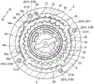
Fig. 2 is a sectional view taken along line II-II of fig. 1.
Fig. 3 is a sectional view taken along line III-III of fig. 1.
Fig. 4 is an in-line view of fig. 1.
Fig. 5 is a view along the line V-V of fig. 1.
Fig. 6 is an enlarged front view showing a part of the gear member of the first embodiment.
Fig. 7 is an enlarged front view showing another part of the gear member of the first embodiment.
Fig. 8 is a diagram showing a valve timing adjusting apparatus according to a second embodiment, and is a sectional view taken along line VIII-VIII of fig. 9.
Fig. 9 is a cross-sectional view taken along line IX-IX of fig. 8.
Fig. 10 is an X-X sectional view of fig. 8.
Fig. 11 is a line drawing XI-XI of fig. 8.
Fig. 12 is a view along line XII-XII of fig. 8.
Fig. 13 is a cross-sectional view showing a modification of fig. 8.
Fig. 14 is a schematic diagram for explaining a conventional problem.
Detailed Description
Hereinafter, a plurality of embodiments of the present disclosure will be described based on the drawings. In addition, in each embodiment, the same reference numerals are given to corresponding components, and redundant description thereof may be omitted. In the case where only a part of the configuration is described in each embodiment, the configuration of the other embodiment described above can be applied to the other part of the configuration. In addition, not only the combinations of the configurations described in the description of the respective embodiments but also the configurations of the plurality of embodiments may be partially combined without being described unless otherwise specified, as long as the combinations do not particularly hinder the description.
(first embodiment)
As shown in fig. 1, a valve timing adjustment device (valve timing device)1 according to a first embodiment of the present disclosure is provided in a transmission system for transmitting a crank torque (crank torque) from a crankshaft (not shown) of an internal combustion engine to a camshaft 2 in a vehicle. Here, the camshaft 2 serves as a shaft for opening and closing an intake valve (not shown) in a valve system of the internal combustion engine by transmission of crank torque. Therefore, the apparatus 1 is configured by the electric motor 4, the control system 7, the phase adjustment system 8, and the like in order to adjust the valve timing of the intake valve.
The electric motor 4 is, for example, a brushless motor or the like, and has a motor housing 5 fixed to a fixed joint of the internal combustion engine and a motor shaft 6 supported by the housing 5 to be rotatable in forward and reverse directions. The control system 7 is constituted by a drive driver, a microcomputer for controlling the drive driver, and the like, and is disposed outside and/or inside the motor case 5 and electrically connected to the electric motor 4. The control system 7 controls the energization of the electric motor 4 to generate a motor torque and rotationally drive the motor shaft 6.
As shown in fig. 1 to 5, the phase adjustment system 8 includes a driving rotor 10, a driven rotor 20, a carrier 30, and a planetary gear 50.
The driving rotor 10 includes a gear member 11, a cover member 13, and a plurality of fastening members 15 for coaxially fastening the two members 11 and 13. The gear member 11 is formed in a cylindrical shape from metal. As shown in fig. 1 to 3, the gear member 11 is formed with a drive-side internal gear portion 12 in which a tooth top circle (tooth) is set on an inner peripheral side of a tooth root circle (tooth bottom circle). Here, the driving-side internal gear portion 12 of the present embodiment employs a cycloid gear.
As shown in fig. 1 and 5, the cover member 13 is formed of metal in a circular ring plate shape. The cover member 13 is disposed on the opposite side of the electric motor 4 in the axial direction with the gear member 11 interposed therebetween. The cover member 13 is formed with a plurality of sprocket teeth 18 projecting to the outer peripheral side from positions spaced at equal intervals in the circumferential direction. The cover member 13 is connected to the crankshaft by a transmission member 3 such as a timing chain being disposed between the sprocket 18 and the plurality of teeth of the crankshaft. In this coupled state, the crank torque of the crankshaft is transmitted to the cover member 13 via the transmission member 3, and the driving rotary body 10 rotates about the rotation center line O in conjunction with the crankshaft. Here, the rotational direction of the driving rotor 10 is one side in the circumferential direction (i.e., counterclockwise in fig. 2 and 3).
As shown in fig. 1 to 5, each fastening member 15 is a screw made of metal. The fastening members 15 are disposed at positions eccentric from the rotation center line O of the driving rotor 10 and spaced at equal intervals in the circumferential direction of the driving rotor 10. That is, the fastening members 15 are arranged substantially parallel to the rotation center line O and at equal intervals around the rotation center line O. Each fastening member 15 of the present embodiment is disposed on the electric motor 4 side in the axial direction from the position where the sprocket 18 is formed in the driving rotor 10.
Each fastening member 15 is integrally provided with a male screw portion 150 and a head portion 151. Here, the male screw portion 150 is inserted with a gap into the through hole 110 axially penetrating the gear member 11. The male screw 150 is also screwed into the female screw hole 130 that penetrates the cover member 13 in the axial direction. A seating surface 151a shown in fig. 1 is formed on the head 151 so as to sandwich the gear member 11 between the cover member 13 screwed to the male screw 150.
The gear member 11 axially fastened by the fastening members 15 and the cover member 13 cover the housing space 14 together as shown in fig. 1 to 3. The housing space 14 houses components 20, 30, and 50 other than the driving rotor 10 in the phase adjustment system 8.
As shown in fig. 1 and 3 to 5, the driven rotating body 20 is formed in a bottomed cylindrical shape from a metal. The driven rotary body 20 is coaxially fitted to the inner peripheral side of the cover member 13. As shown in fig. 1, 4, and 5, the driven rotary body 20 has a coupling portion 22 formed on the bottom wall portion and coupled to the camshaft 2 coaxially therewith. In this coupled state, the driven rotary body 20 rotates about the rotation center line O in conjunction with the camshaft 2 by transmission of the crank torque. At this time, the driven rotor 20 can rotate relative to the driving rotor 10 by the transmission of the motor torque. Here, the rotational direction of the driven rotary body 20 that coincides with the rotational direction of the camshaft 2 is one side in the circumferential direction (i.e., counterclockwise in fig. 3) that is the same as the rotational direction of the driving rotary body 10. As shown in fig. 3 to 5, the relative rotation direction of the driven rotary body 20 with respect to the driving rotary body 10 is an advance angle direction Da in which one side rotation in the circumferential direction is advanced and a retard angle direction Dr in which the other side rotation in the circumferential direction is retarded.
As shown in fig. 1 and 3, the driven rotary body 20 has a driven-side internal gear portion 24 formed in a peripheral wall portion thereof, the driven-side internal gear portion having a tooth crest circle set on an inner peripheral side of a tooth root circle. Here, the driven-side internal gear portion 24 of the present embodiment employs a cycloid gear. The number of teeth of the driven-side inner gear portion 24 is set to be smaller than that of the driving-side inner gear portion 12. The driven-side internal gear portion 24 is offset toward the camshaft 2 in the axial direction with respect to the driving-side internal gear portion 12.
As shown in fig. 1 to 4, the carrier 30 is formed of metal in a partially eccentric cylindrical shape. The carrier 30 is disposed in the axial direction extending from the inner peripheral side of the driven rotor 20 toward the inner peripheral side of the gear member 11 in the housing space 14. As shown in fig. 1 to 3, the carrier 30 forms an input portion 31 by a cylindrical inner peripheral surface coaxial with the rotating bodies 10 and 20 and the motor shaft 6. The input portion 31 is connected to the motor shaft 6 via a connection joint 33 so as to be rotatable integrally. In this coupled state, the carrier 30 is rotated about the rotation center line O in conjunction with the motor shaft 6 by transmission of the motor torque, and is relatively rotatable with respect to the drive-side internal gear portion 12 of the drive rotor 10. Here, the rotation direction of the carrier 30 that coincides with the rotation direction of the motor shaft 6 is one of a normal rotation direction that is one side in the circumferential direction (i.e., the counterclockwise direction in fig. 2 and 3) and a reverse rotation direction that is the other side in the circumferential direction (i.e., the clockwise direction in fig. 2 and 3) that corresponds to the motor torque. As shown in fig. 2 and 3, the relative rotational direction of the carrier 30 with respect to the drive side inner gear portion 12 is the advancing angle direction Da in which one side rotation in the circumferential direction advances, and the retarding angle direction Dr in which the other side rotation in the circumferential direction retards.
The carrier 30 shown in fig. 1 to 3 further includes a support portion 34 formed by a cylindrical planar outer peripheral surface eccentric to the rotating bodies 10 and 20 and the motor shaft 6. The support portion 34 is coaxially fitted to the inner peripheral side of the planetary gear 50 via a planetary bearing 35. The planet gears 50 in the engaged state are radially supported by the support portions 34, and can perform a planetary motion in accordance with the relative rotation of the carrier 30 with respect to the drive side internal gear portion 12. Here, the planetary motion refers to a motion in which the planetary gear 50 rotates on its own axis and revolves in either one of forward and reverse rotational directions of the carrier 30.
The planetary gear 50 is formed of metal into a stepped cylindrical shape. The planetary gear 50 is disposed in the axial direction extending from the inner peripheral side of the driven rotating body 20 toward the inner peripheral side of the gear member 11 in the housing space 14. The planetary gear 50 is formed with a drive side outer gear portion 52 and a driven side outer gear portion 54 having addendum circles set on the outer peripheral side of the root circle. Here, cycloid gears are used for the driving side outer gear portion 52 and the driven side outer gear portion 54 of the present embodiment. The number of teeth of the driving side outer gear portion 52 and the driven side outer gear portion 54 is set to be smaller than the number of teeth of the driving side inner gear portion 12 and the driven side inner gear portion 24 by the same number, respectively. The drive side outer gear portion 52 is disposed eccentrically to the inner peripheral side of the gear member 11, and meshes with the drive side inner gear portion 12 and is capable of planetary motion. The driven side outer gear portion 54 is offset to the camshaft 2 side in the axial direction with respect to the driving side outer gear portion 52. As shown in fig. 1 and 3, the driven outer gear portion 54 is disposed eccentrically to the inner peripheral side of the driven rotary body 20, and is meshed with the driven inner gear portion 24 so as to be capable of planetary motion.
With the above configuration, in the phase adjustment system 8 in which the rotary bodies 10 and 20 are gear-connected to each other, the rotational phase (hereinafter, simply referred to as "rotational phase") between the driving rotary body 10 and the driven rotary body 20 is determined based on the motor torque controlled by the control system 7. The valve timing of the intake valve is adapted to the operating condition of the internal combustion engine by following the rotational phase.
Specifically, when the carrier 30 rotates forward together with the motor shaft 6 at the same speed as the driving rotor 10, the carrier 30 does not rotate relative to the driving-side internal gear portion 12. As a result, the planetary gear 50 does not perform a planetary motion but rotates together with the rotary bodies 10 and 20, so that the rotational phase is substantially unchanged and the valve timing is kept adjusted. On the other hand, when the carrier 30 rotates forward at a higher speed than the driving rotary body 10 together with the motor shaft 6, the carrier 30 rotates in the lead angle direction Da relative to the driving-side internal gear portion 12. As a result, the planetary gear 50 performs a planetary motion, and the driven rotary member 20 rotates relative to the driving rotary member 10 in the advance direction Da, so that the rotational phase is changed to advance the valve timing. On the other hand, when the carrier 30 rotates forward or backward at a lower speed than the driving rotary body 10 together with the motor shaft 6, the carrier 30 rotates in the retarded angle direction Dr with respect to the driving side internal gear portion 12. As a result, the planetary gear 50 performs a planetary motion, and the driven rotary member 20 rotates in the retard direction Dr with respect to the driving rotary member 10, so that the rotational phase changes by a retard angle, and the valve timing is adjusted by a retard angle.
(stopper structure)
Next, the stopper structure 60 provided in the phase adjustment system 8 will be described in detail.
As shown in fig. 3, the stopping structure 60 is constructed by combining a stopping groove 62 provided in the gear member 11 of the driving rotating body 10 and a stopping protrusion 64 provided in the driven rotating body 20.
The stopper groove 62 is formed in the gear member 11 as an arc groove that opens to the inner peripheral side and extends in the circumferential direction. An inner end surface in the advance angle direction Da in the stopper groove 62 forms a driving-side advance angle stopper wall 62 a. An inner end surface in the retard angle direction Dr in the stopper groove 62 forms a drive-side retard angle stopper wall 62 r.
The stopper projection 64 is formed in a substantially fan shape protruding toward the outer peripheral side in the driven rotary body 20. The stopper projection 64 is swingable to one side and the other side in the circumferential direction in a state of projecting into the stopper groove 62. The side surface in the advance angle direction Da in the stopper projection 64 forms a driven-side advance angle stopper wall 64 a. The side surface in the retarded angle direction Dr of the stopper projection 64 forms a driven-side retarded angle stopper wall 64 r.
As shown by the two-dot chain line in fig. 3, the driven rotary body 20 prevents relative rotation in the same direction Da with respect to the driving rotary body 10 by bringing the driven-side advance angle stopper wall 64a into surface contact with the driving-side advance angle stopper wall 62a in the advance angle direction Da. At this time, the change in the rotational phase is limited to the maximum lead angle phase which is the phase end in the lead angle direction Da. Therefore, the driven rotator 20 is relatively rotated in the advancing direction Da with respect to the driving rotator 10 by the motor torque, and the driven-side advancing stop wall 64a collides with the driving-side advancing stop wall 62a, thereby generating a collision torque.
On the other hand, as shown by the solid line in fig. 3, the driven rotary body 20 prevents relative rotation in the retard direction Dr with respect to the driving rotary body 10 by surface-contacting the driven-side retard stop wall 64r with the driving-side retard stop wall 62r in the retard direction Dr. At this time, the change of the rotational phase is limited at the most retarded angle phase which is the phase end in the retarded angle direction Dr. Therefore, the driven rotor 20 rotates in the retarded angle direction Dr relative to the driving rotor 10 by the motor torque, and the driven-side retarded angle stopper wall 64r collides with the driving-side retarded angle stopper wall 62r, thereby generating a collision torque.
As shown in fig. 6, the advancing direction Da of the present embodiment coincides with the approaching direction in which the driven-side advancing stop wall 64a approaches the driving-side advancing stop wall 62 a. In the lead angle direction Da, which is the approaching direction, a drive-side lead angle stopper wall 62a is formed between a specific tooth bottom portion 111a of the drive-side internal gear portion 12 of the gear member 11 and a specific tooth top portion 112a of the drive-side internal gear portion 12 located on the inner side of the specific tooth bottom portion 111 a.
Here, in particular, the drive side lead angle stopper wall 62a is continuous in a radial range between an addendum circle Ct passing through the specific tooth top portion 112a and a root circle Cb passing through the specific tooth bottom portion 111a at an outer peripheral side from the root circle Cb. In the lead angle direction Da, the drive-side lead angle stopper wall 62a is continuous over a circumferential range extending from a position separated from the tooth surface 113a between the specific tooth bottom 111a and the specific tooth top 112a to the tooth surface 115a between the specific tooth top 112a and the tooth bottom 114a on the further back side. In addition, the drive-side advance angle stopper wall 62a is connected to the drive-side internal gear portion 12 in the axial direction.
With this configuration, the thickness of the drive-side advance stop wall 62a can be ensured to be large in the advance direction Da in the section from between the specific tooth bottom 111a and the specific tooth top 112a to the tooth bottom 114a on the back side of the specific tooth top 112 a.
On the other hand, as shown in fig. 7, the retardation direction Dr of the present embodiment coincides with the approaching direction in which the driven-side retardation angle stop wall 64r approaches the driving-side retardation angle stop wall 62 r. In the retard angle direction Dr, which is the approaching direction, the drive side retard angle stopper wall 62r is formed between the specific tooth bottom portion 111r of the drive side internal gear portion 12 and the specific tooth top portion 112r of the drive side internal gear portion 12 located further to the rear side than the specific tooth bottom portion 111r in the gear member 11.
Here, in particular, the drive-side retard angle stopper wall 62r is continuous in a radial range between an addendum circle Ct that crosses the specific tooth top portion 112r and a root circle Cb that crosses the specific tooth bottom portion 111r at an outer peripheral side from the root circle Cb. In the retardation direction Dr, the drive-side retardation angle stopper wall 62r is continuous in a circumferential range extending from a position separated from the tooth surface 113r between the specific tooth bottom portion 111r and the specific tooth top portion 112r to the tooth surface 115r between the specific tooth top portion 112r and the tooth bottom portion 114r on the further back side. In addition, the drive-side retard stopper wall 62r is axially connected to the drive-side internal gear portion 12.
With this configuration, the thickness of the drive-side retard angle stopper wall 62r can be secured large in the retard angle direction Dr in the section from between the specific tooth bottom portion 111r and the specific tooth top portion 112r to the tooth bottom portion 114r on the back side of the specific tooth top portion 112 r.
As described above, in the present embodiment, the drive-side advance angle stopper wall 62a and the drive-side retard angle stopper wall 62r correspond to "drive-side stopper walls". Meanwhile, in the present embodiment, the driven-side advance angle stopper wall 64a and the driven-side retard angle stopper wall 64r correspond to "driven-side stopper walls".
(Effect)
The operational effects of the first embodiment described above will be described below.
The gear member 11 meshing with the planetary gear 50 in the driving rotor 10 of the first embodiment forms a driving-side advance angle stopper wall 62a and a driving-side retard angle stopper wall 62 r. Therefore, the collision torque generated when the driven-side advance angle stopper wall 64a of the driven rotary body 20 collides with the driving-side advance angle stopper wall 62a of the gear member 11 is transmitted from the driven rotary body 20 to the planetary gear 50, and further transmitted from the planetary gear 50 to the gear member 11. The transmission of the collision torque to the gear member 11 is prevented by the driven-side advance angle stopper wall 64a contacting the driving-side advance angle stopper wall 62a, and the transmission of the collision torque to the gear member 11 and the cover member 13 can be suppressed. Similarly, the collision torque generated when the driven-side retard angle stop wall 64r of the driven rotary body 20 collides with the drive-side retard angle stop wall 62r of the gear member 11 is transmitted from the driven rotary body 20 to the planetary gear 50, and further transmitted from the planetary gear 50 to the gear member 11. The transmission of the collision torque to the gear member 11 is prevented by the driven-side retard limit wall 64r contacting the driving-side retard limit wall 62r, and the transmission of the collision torque to the gear member 11 and the cover member 13 can be suppressed.
As a result, the action of the relative torque due to the collision torque can be suppressed between the gear member 11 fastened by the plurality of fastening members 15 and the cover member 13, and therefore, the fastening members 15 are less likely to loosen due to the collision torque. Therefore, it is possible to avoid the occurrence of wear and abnormal noise at the meshing position between the gear member 11 inclined due to the loosening of each fastening member 15 and the planetary gear 50, and to ensure durability and silencing performance.
Further, according to the first embodiment, the action of the relative torque due to the collision torque can be suppressed by the principle described above between the gear member 11 and the cover member 13 that are fastened in the axial direction by the fastening member 15 that is eccentric from the rotation center line O of the driving rotor 10, that is, by a plurality of screws. Accordingly, the arc sliding phenomenon can be prevented from occurring on the seat surface 151a of each screw which is in contact with the gear member 11, and therefore, the screw is less likely to be loosened. Therefore, it is possible to avoid the occurrence of wear and abnormal noise at the meshing position between the gear member 11 inclined due to loosening of each screw and the planetary gear 50, and to ensure durability and silencing performance.
Further, according to the first embodiment, the advancing direction Da coincides with the approaching direction in which the driven-side advancing stop wall 64a approaches the driving-side advancing stop wall 62a in the relative rotation direction of the driven rotary body 20 with respect to the driving rotary body 10. In the lead angle direction Da, which is the approaching direction, a drive-side lead angle stopper wall 62a is formed between a specific tooth bottom 111a and a specific tooth top 112a on the back side of the gear member 11. Thus, the thickness of the drive-side lead angle stopper wall 62a can be secured large in the lead angle direction Da in the section from between the specific tooth bottom 111a and the specific tooth top 112a to the tooth bottom 114a on the back side of the specific tooth top 112 a. Therefore, the driving-side advance angle stopper wall 62a can be prevented from being damaged by the collision torque, and high durability can be ensured.
In addition, according to the first embodiment, the retarded angle direction D coincides with the approaching direction in which the driven-side retarded angle stopper wall 64r approaches the driving-side retarded angle stopper wall 62r in the relative rotation direction of the driven rotary body 20 with respect to the driving rotary body 10. In the retard angle direction Dr, which is the approaching direction, a drive-side retard angle stopper wall 62r is formed between the specific tooth bottom portion 111r and the specific tooth top portion 112r on the back side in the gear member 11. Thus, in the retard angle direction Dr, the thickness of the drive-side retard angle stopper wall 62r can be secured large in the section from between the specific tooth bottom portion 111r and the specific tooth top portion 112r to the tooth bottom portion 114r on the back side of the specific tooth top portion 112 r. Therefore, the driving-side retardation wall 62r can be prevented from being damaged by the collision torque, and high durability can be ensured.
(second embodiment)
As shown in fig. 8 to 12, the second embodiment of the present disclosure is a modification of the first embodiment. The driving rotor 2010 of the second embodiment has a gear member 2011, a cover member 2013, and a plurality of fastening members 2015 for coaxially fastening the two members 2011 and 2013, which are different from those of the first embodiment.
Specifically, as shown in fig. 8 and 13, the plurality of sprocket teeth 18 are not provided in the metal cover member 2013. Instead, as shown in fig. 8, 9, and 11, a plurality of sprocket teeth 2018 are provided on the metal gear member 2011 together with the drive-side internal gear portion 12. Here, each sprocket tooth 2018 protrudes from the gear member 2011 to the outer peripheral side at positions equally spaced in the circumferential direction. The gear member 2011 is connected to the crankshaft by the transmission member 3 being disposed between the sprocket tooth 2018 and the plurality of teeth of the crankshaft. In this connected state, the crank torque of the crankshaft is transmitted to gear member 2011 via transmission member 3, and driving rotating body 2010 rotates around rotation center line O in conjunction with the crankshaft. Here, the rotational direction of the driving rotor 2010 is the same as that of the first embodiment in one circumferential direction (i.e., counterclockwise direction in fig. 9 and 10).
As shown in fig. 8 to 12, the fastening members 2015 are disposed in the driving rotor 2010 so as to be offset from the positions where the sprocket 2018 is formed toward the camshaft 2 in the axial direction. An external thread portion 2150 and a head portion 2151, which are different from those of the first embodiment, are integrally provided on each fastening member 2015. Here, the male screw portion 2150 is inserted with a gap into a through hole 2130 that axially penetrates the cover member 2013 on the side axially opposite to the electric motor 4 with the gear member 2011 interposed therebetween. The external thread portion 2150 is further screwed into the internal thread hole 2110 axially penetrating the gear member 2011. A seat surface 2151a shown in fig. 8 is formed on the head 2151 so as to sandwich the cover member 2013 between the gear members 2011 to which the male screw portions 2150 are screwed.
The second embodiment is the same as the first embodiment except for the above-described configuration. Therefore, the same operational effects as those of the first embodiment among the operational effects of the second embodiment will not be described below, and additional operational effects of the first embodiment will be described below.
The gear part 2011 meshing with the planetary gear 50 in the driving rotating body 10 of the second embodiment is transmitted with crank torque from the crankshaft. As a result, the crank torque is transmitted from the gear member 2011 to the planetary gear 50, and further transmitted from the planetary gear 50 to the driven rotor 20 and the camshaft 2 in order, so that the camshaft 2 opens and closes the intake valve. At this time, the action of the relative torque due to the crank torque can be suppressed between the gear member 2011 fastened in the axial direction by the fastening members 2015 and the cover member 2013, and therefore the fastening members 2015 are less likely to loosen due to the crank torque. Further, between the gear member 2011 and the cover member 2013, the action of the relative torque due to the collision torque can be suppressed by the same principle as in the first embodiment, and therefore, the fastening members 2015 are also less likely to be loosened due to the collision torque. As described above, the function of avoiding the wear and the abnormal noise caused at the meshing position between the gear member 2011 inclined due to the backlash of the fastening members 2015 and the planetary gear 50 can be improved, and therefore the reliability of the effect of ensuring the durability and the silencing performance can be improved.
(other embodiments)
While the embodiments of the present disclosure have been described above, the present disclosure is not limited to these embodiments and can be applied to various embodiments and combinations without departing from the scope of the present disclosure.
As modification 1 of the first and second embodiments, the cover members 13 and 2013 may be disposed on the side opposite to the camshaft 2 with the gear members 11 and 2011 interposed therebetween in the axial direction. As a modification 2 of the second embodiment, the cover member 2013 may be formed of a resin as shown in fig. 13. Here, since the action of the relative torque due to the crank torque and the collision torque can be suppressed between the gear member 2011 and the cover member 2013, modification 2 can be adopted in accordance with the case where the strength required of the cover member 2013 is reduced.
In the lead angle direction Da according to modification 3 of the first and second embodiments, the drive-side lead angle stopper wall 62a may be formed at a position deviated from between the specific tooth bottom portion 111a and the specific tooth tip portion 112a on the back side. In the retardation direction Dr according to modification 4 of the first and second embodiments, the drive-side retardation angle stopper wall 62r may be formed at a position deviated from between the specific tooth bottom portion 111r and the specific tooth top portion 112r on the back side.
As modification 5 of the first and second embodiments, the plurality of fastening members 15 and 2015 may be arranged at unequal intervals in the circumferential direction. As modification 6 of the first and second embodiments, the fastening members 15 and 2015 may be rivets or the like other than screws.
As modification 7 of the first and second embodiments, for example, an output shaft of an electromagnetic brake other than the electric motor 4 may be coupled to the input portion 31 of the carrier 30. As modification 8 of the first and second embodiments, the present disclosure may be applied to a device for adjusting the valve timing of an exhaust valve in a valve of an internal combustion engine.
The valve timing adjusting apparatus 1 of the first publication adjusts the valve timing of the valve operating valve that is opened and closed by the camshaft 2 through transmission of crank torque from the crankshaft in the internal combustion engine. The valve timing adjusting apparatus 1 includes driving rotors 10 and 2010, a driven rotor 20, and a planetary gear 50. The driving rotor 10, 2010 has a driving side stopper wall 62a, 62r and rotates in conjunction with the crankshaft. The driven rotary body 20 has driven side stopper walls 64a, 64 r. The driven rotary body 20 rotates in conjunction with the camshaft and relatively rotates with respect to the driving rotary body, so that the rotational phase with the driving rotary body varies. The driven rotor 20 restricts the change of the rotational phase by bringing the driven-side stopper wall into contact with the driving-side stopper wall in the relative rotational directions Da and Dr with respect to the driving rotor. The planetary gear 50 changes the rotational phase by engaging with the driving rotor and the driven rotor and performing planetary motion. The drive rotor includes gear members 11 and 2011, cover members 13 and 2013, and fastening members 15 and 2015. The gear members 11, 2011 form drive side stopper walls and mesh with the planetary gears. The cover members 13 and 2013 cover the housing space 14 that houses the driven rotary body and the planetary gears together with the gear members. The fastening members 15, 2015 fasten the gear member and the cover member in the axial direction.
The gear member in this first disclosed drive rotating body, which meshes with the planetary gear, forms a drive-side stopper wall. Therefore, the collision torque generated when the driven side stopper wall of the driven rotary body collides with the drive side stopper wall of the gear member is transmitted from the driven rotary body to the planetary gear, and further transmitted from the planetary gear to the gear member. In this way, the transmission of the collision torque to the gear member is prevented by the driven-side stopper wall in contact with the driving-side stopper wall, and the transmission of the collision torque to the gear member and the cover member can be suppressed. As a result, the action of the relative torque due to the collision torque can be suppressed between the gear member axially fastened by the fastening member and the cover member, and therefore the fastening member is less likely to loosen due to the collision torque. Therefore, it is possible to avoid the occurrence of wear and abnormal noise at the meshing position between the gear member inclined due to loosening of the fastening member and the planetary gear, and to ensure durability and silencing performance.
The fastening member of the second disclosure is a screw disposed eccentrically from the rotation center line O of the driving rotor.
According to the second disclosure, the action of the relative torque due to the collision torque can be suppressed by the principle of the first disclosure between the gear member and the cover member that are fastened in the axial direction by the screw that is the fastening member eccentric from the rotation center line of the driving rotating body. Accordingly, the arc sliding phenomenon on the seat surface of the screw contacting with the gear component can be prevented, and the screw is difficult to loosen. Therefore, it is possible to avoid the occurrence of wear and abnormal noise at the meshing position between the gear member inclined due to loosening of the screw and the planetary gear, and to ensure durability and silencing performance.
The present disclosure is described based on embodiments, but the present disclosure should not be construed as being limited to the embodiments and configurations. The present disclosure also includes various modifications and equivalent arrangements. In addition, various combinations and modes, and further, other combinations and modes in which only one element, one or more elements, or the following elements are included in the various combinations and modes also fall within the scope and spirit of the present disclosure.
Claims (4)
1. A valve timing adjustment device for adjusting the valve timing of a valve that is opened and closed by a camshaft (2) through transmission of crank torque from a crankshaft in an internal combustion engine, the valve timing adjustment device comprising:
a driving rotating body (10, 2010) having a driving side stopper wall (62a, 62r) and rotating in conjunction with the crankshaft;
a driven rotor (20) having a driven-side stopper wall (64a, 64r) that rotates in conjunction with the camshaft (2) and rotates relative to the driving rotor (10, 2010) to change a rotational phase with the driving rotor (10, 2010), and that is restricted from changing in the rotational phase by bringing the driven-side stopper wall (64a, 64r) into contact with the driving-side stopper wall (62a, 62r) in a relative rotational direction (Da, Dr) with respect to the driving rotor (10, 2010); and
a planetary gear (50) which changes the rotational phase by engaging with the driving rotating body (10, 2010) and the driven rotating body (20) and performing planetary motion,
the drive rotating body (10, 2010) includes:
a gear member (11, 2011) which forms a gear portion that meshes with the planetary gear (50) and forms the drive-side stopper wall (62a, 62 r);
a cover member (13, 2013) that covers, together with the gear member (11, 2011), a housing space (14) that houses the driven rotating body (20) and the planetary gear (50); and
a fastening member (15, 2015) that axially fastens the gear member (11, 2011) and the cover member (13, 2013);
the driven rotating body (20) is configured to transmit collision torque generated when the driving-side stopper wall (62a) collides with the driven-side stopper wall (64a) to the gear member (11), and to suppress transmission of the collision torque between the gear member (11) and the cover member (13).
2. The valve timing adjusting apparatus according to claim 1,
the fastening member (15, 2015) is a screw eccentrically disposed from a rotation center line (O) of the driving rotor (10, 2010).
3. The valve timing adjustment apparatus according to claim 1 or 2,
the crank torque is transmitted from the crank shaft to the gear member (11, 2011), and the driving rotating body (10, 2010) rotates in conjunction with the crank shaft.
4. The valve timing adjustment apparatus according to claim 1 or 2,
in an approaching direction (Da, Dr) in which the driven side stopper wall (64a, 64r) approaches the driving side stopper wall (62a, 62r) in the relative rotation direction (Da, Dr), the driving side stopper wall (62a, 62r) is formed between a specific tooth bottom portion (111a, 111r) of the gear member (11, 2011) and a specific tooth top portion (112a, 112r) of the gear member (11, 2011) located on the inner side than the specific tooth bottom portion.
Applications Claiming Priority (3)
| Application Number | Priority Date | Filing Date | Title |
|---|---|---|---|
| JP2016-081459 | 2016-04-14 | ||
| JP2016081459A JP6443382B2 (en) | 2016-04-14 | 2016-04-14 | Valve timing adjustment device |
| PCT/JP2017/007584 WO2017179322A1 (en) | 2016-04-14 | 2017-02-28 | Valve timing adjustment device |
Publications (2)
| Publication Number | Publication Date |
|---|---|
| CN109072726A CN109072726A (en) | 2018-12-21 |
| CN109072726B true CN109072726B (en) | 2020-10-30 |
Family
ID=60042550
Family Applications (1)
| Application Number | Title | Priority Date | Filing Date |
|---|---|---|---|
| CN201780023291.8A Active CN109072726B (en) | 2016-04-14 | 2017-02-28 | Valve timing adjusting device |
Country Status (6)
| Country | Link |
|---|---|
| US (1) | US10830110B2 (en) |
| JP (1) | JP6443382B2 (en) |
| KR (1) | KR102056892B1 (en) |
| CN (1) | CN109072726B (en) |
| DE (1) | DE112017002023T5 (en) |
| WO (1) | WO2017179322A1 (en) |
Families Citing this family (6)
| Publication number | Priority date | Publication date | Assignee | Title |
|---|---|---|---|---|
| KR20230100756A (en) | 2017-09-29 | 2023-07-05 | 닛토덴코 가부시키가이샤 | Laminate, optical member and optical device |
| JP6911827B2 (en) * | 2018-09-10 | 2021-07-28 | 株式会社デンソー | Valve timing adjuster |
| JP7161917B2 (en) * | 2018-10-31 | 2022-10-27 | 株式会社ミクニ | Phase change unit and valve timing change device |
| JP7226780B2 (en) * | 2019-03-15 | 2023-02-21 | 株式会社Soken | valve timing adjuster |
| CN110295964B (en) * | 2019-05-09 | 2021-03-16 | 湖南大兹动力科技有限公司 | Internal combustion engine valve control device regulated by motor |
| JP7211302B2 (en) * | 2019-08-22 | 2023-01-24 | 株式会社デンソー | valve timing adjuster |
Citations (4)
| Publication number | Priority date | Publication date | Assignee | Title |
|---|---|---|---|---|
| JP2007255412A (en) * | 2006-02-24 | 2007-10-04 | Denso Corp | Valve timing adjusting device |
| US20080083384A1 (en) * | 2006-10-06 | 2008-04-10 | Denso Corporation | Valve timing controller |
| CN101305176A (en) * | 2005-11-07 | 2008-11-12 | 丰田自动车株式会社 | Valve timing control device and control method for internal combustion engine |
| US20090017952A1 (en) * | 2007-07-09 | 2009-01-15 | Denso Corporation | Valve timing control apparatus |
Family Cites Families (8)
| Publication number | Priority date | Publication date | Assignee | Title |
|---|---|---|---|---|
| JP4506817B2 (en) * | 2007-11-13 | 2010-07-21 | 株式会社デンソー | Valve timing adjustment device |
| JP4978627B2 (en) | 2009-01-08 | 2012-07-18 | 株式会社デンソー | Valve timing adjustment device |
| JP6090059B2 (en) * | 2013-08-22 | 2017-03-08 | 株式会社デンソー | Valve timing adjustment device |
| JP5924323B2 (en) | 2013-09-18 | 2016-05-25 | 株式会社デンソー | Valve timing adjustment device |
| JP5862696B2 (en) | 2014-01-29 | 2016-02-16 | 株式会社日本自動車部品総合研究所 | Valve timing adjustment device |
| JP5987868B2 (en) * | 2014-07-22 | 2016-09-07 | 株式会社デンソー | Valve timing adjustment device |
| JP6399587B2 (en) | 2014-10-22 | 2018-10-03 | シャープ株式会社 | Information processing apparatus, information processing system, information processing method, and information processing program |
| JPWO2016113834A1 (en) * | 2015-01-13 | 2017-10-19 | 日鍛バルブ株式会社 | Phase change device for automotive engine |
-
2016
- 2016-04-14 JP JP2016081459A patent/JP6443382B2/en active Active
-
2017
- 2017-02-28 CN CN201780023291.8A patent/CN109072726B/en active Active
- 2017-02-28 KR KR1020187023572A patent/KR102056892B1/en active IP Right Grant
- 2017-02-28 DE DE112017002023.9T patent/DE112017002023T5/en active Pending
- 2017-02-28 US US16/092,583 patent/US10830110B2/en active Active
- 2017-02-28 WO PCT/JP2017/007584 patent/WO2017179322A1/en active Application Filing
Patent Citations (4)
| Publication number | Priority date | Publication date | Assignee | Title |
|---|---|---|---|---|
| CN101305176A (en) * | 2005-11-07 | 2008-11-12 | 丰田自动车株式会社 | Valve timing control device and control method for internal combustion engine |
| JP2007255412A (en) * | 2006-02-24 | 2007-10-04 | Denso Corp | Valve timing adjusting device |
| US20080083384A1 (en) * | 2006-10-06 | 2008-04-10 | Denso Corporation | Valve timing controller |
| US20090017952A1 (en) * | 2007-07-09 | 2009-01-15 | Denso Corporation | Valve timing control apparatus |
Also Published As
| Publication number | Publication date |
|---|---|
| KR20180100688A (en) | 2018-09-11 |
| WO2017179322A1 (en) | 2017-10-19 |
| DE112017002023T5 (en) | 2019-01-24 |
| JP6443382B2 (en) | 2018-12-26 |
| JP2017190746A (en) | 2017-10-19 |
| CN109072726A (en) | 2018-12-21 |
| US10830110B2 (en) | 2020-11-10 |
| US20190120091A1 (en) | 2019-04-25 |
| KR102056892B1 (en) | 2019-12-17 |
Similar Documents
| Publication | Publication Date | Title |
|---|---|---|
| CN109072726B (en) | Valve timing adjusting device | |
| JP4390078B2 (en) | Valve timing adjustment device | |
| WO2016031557A1 (en) | Valve opening/closing timing control device | |
| JP2016023591A (en) | Valve timing adjustment device | |
| US8127729B2 (en) | Valve timing control apparatus | |
| WO2003056141A1 (en) | Planetary gear type variable valve timing device | |
| JP2012189050A (en) | Valve timing adjustment device | |
| JP4978627B2 (en) | Valve timing adjustment device | |
| CN111577420A (en) | Valve timing changing device | |
| JP7294745B2 (en) | valve timing adjuster | |
| US20150083061A1 (en) | Cam phaser with eccentric lantern gear component | |
| JP2020125688A (en) | Valve timing adjustment device | |
| CN113167140B (en) | Valve timing adjusting device | |
| JP2012237203A (en) | Valve timing adjuster | |
| JP2009074398A (en) | Valve timing adjusting device | |
| WO2020189482A1 (en) | Valve timing adjusting device | |
| JP7226780B2 (en) | valve timing adjuster | |
| JP4428352B2 (en) | Valve timing adjustment device | |
| JP2014058878A (en) | Valve timing adjusting device | |
| JP2024119301A (en) | Valve timing adjustment device | |
| JP2009007952A (en) | Valve timing adjusting device |
Legal Events
| Date | Code | Title | Description |
|---|---|---|---|
| PB01 | Publication | ||
| PB01 | Publication | ||
| SE01 | Entry into force of request for substantive examination | ||
| SE01 | Entry into force of request for substantive examination | ||
| GR01 | Patent grant | ||
| GR01 | Patent grant |