CN109045433B - Medical tube and method of manufacture - Google Patents
Medical tube and method of manufacture Download PDFInfo
- Publication number
- CN109045433B CN109045433B CN201811053333.5A CN201811053333A CN109045433B CN 109045433 B CN109045433 B CN 109045433B CN 201811053333 A CN201811053333 A CN 201811053333A CN 109045433 B CN109045433 B CN 109045433B
- Authority
- CN
- China
- Prior art keywords
- tube
- medical tube
- wall
- opening
- region
- Prior art date
- Legal status (The legal status is an assumption and is not a legal conclusion. Google has not performed a legal analysis and makes no representation as to the accuracy of the status listed.)
- Active
Links
Images


Classifications
-
- A—HUMAN NECESSITIES
- A61—MEDICAL OR VETERINARY SCIENCE; HYGIENE
- A61M—DEVICES FOR INTRODUCING MEDIA INTO, OR ONTO, THE BODY; DEVICES FOR TRANSDUCING BODY MEDIA OR FOR TAKING MEDIA FROM THE BODY; DEVICES FOR PRODUCING OR ENDING SLEEP OR STUPOR
- A61M16/00—Devices for influencing the respiratory system of patients by gas treatment, e.g. mouth-to-mouth respiration; Tracheal tubes
- A61M16/08—Bellows; Connecting tubes ; Water traps; Patient circuits
- A61M16/0875—Connecting tubes
-
- A—HUMAN NECESSITIES
- A61—MEDICAL OR VETERINARY SCIENCE; HYGIENE
- A61M—DEVICES FOR INTRODUCING MEDIA INTO, OR ONTO, THE BODY; DEVICES FOR TRANSDUCING BODY MEDIA OR FOR TAKING MEDIA FROM THE BODY; DEVICES FOR PRODUCING OR ENDING SLEEP OR STUPOR
- A61M16/00—Devices for influencing the respiratory system of patients by gas treatment, e.g. mouth-to-mouth respiration; Tracheal tubes
- A61M16/0003—Accessories therefor, e.g. sensors, vibrators, negative pressure
-
- A—HUMAN NECESSITIES
- A61—MEDICAL OR VETERINARY SCIENCE; HYGIENE
- A61M—DEVICES FOR INTRODUCING MEDIA INTO, OR ONTO, THE BODY; DEVICES FOR TRANSDUCING BODY MEDIA OR FOR TAKING MEDIA FROM THE BODY; DEVICES FOR PRODUCING OR ENDING SLEEP OR STUPOR
- A61M16/00—Devices for influencing the respiratory system of patients by gas treatment, e.g. mouth-to-mouth respiration; Tracheal tubes
- A61M16/021—Devices for influencing the respiratory system of patients by gas treatment, e.g. mouth-to-mouth respiration; Tracheal tubes operated by electrical means
-
- A—HUMAN NECESSITIES
- A61—MEDICAL OR VETERINARY SCIENCE; HYGIENE
- A61M—DEVICES FOR INTRODUCING MEDIA INTO, OR ONTO, THE BODY; DEVICES FOR TRANSDUCING BODY MEDIA OR FOR TAKING MEDIA FROM THE BODY; DEVICES FOR PRODUCING OR ENDING SLEEP OR STUPOR
- A61M16/00—Devices for influencing the respiratory system of patients by gas treatment, e.g. mouth-to-mouth respiration; Tracheal tubes
- A61M16/06—Respiratory or anaesthetic masks
-
- A—HUMAN NECESSITIES
- A61—MEDICAL OR VETERINARY SCIENCE; HYGIENE
- A61M—DEVICES FOR INTRODUCING MEDIA INTO, OR ONTO, THE BODY; DEVICES FOR TRANSDUCING BODY MEDIA OR FOR TAKING MEDIA FROM THE BODY; DEVICES FOR PRODUCING OR ENDING SLEEP OR STUPOR
- A61M16/00—Devices for influencing the respiratory system of patients by gas treatment, e.g. mouth-to-mouth respiration; Tracheal tubes
- A61M16/10—Preparation of respiratory gases or vapours
- A61M16/1075—Preparation of respiratory gases or vapours by influencing the temperature
- A61M16/109—Preparation of respiratory gases or vapours by influencing the temperature the humidifying liquid or the beneficial agent
-
- A—HUMAN NECESSITIES
- A61—MEDICAL OR VETERINARY SCIENCE; HYGIENE
- A61M—DEVICES FOR INTRODUCING MEDIA INTO, OR ONTO, THE BODY; DEVICES FOR TRANSDUCING BODY MEDIA OR FOR TAKING MEDIA FROM THE BODY; DEVICES FOR PRODUCING OR ENDING SLEEP OR STUPOR
- A61M16/00—Devices for influencing the respiratory system of patients by gas treatment, e.g. mouth-to-mouth respiration; Tracheal tubes
- A61M16/10—Preparation of respiratory gases or vapours
- A61M16/1075—Preparation of respiratory gases or vapours by influencing the temperature
- A61M16/1095—Preparation of respiratory gases or vapours by influencing the temperature in the connecting tubes
-
- A—HUMAN NECESSITIES
- A61—MEDICAL OR VETERINARY SCIENCE; HYGIENE
- A61M—DEVICES FOR INTRODUCING MEDIA INTO, OR ONTO, THE BODY; DEVICES FOR TRANSDUCING BODY MEDIA OR FOR TAKING MEDIA FROM THE BODY; DEVICES FOR PRODUCING OR ENDING SLEEP OR STUPOR
- A61M16/00—Devices for influencing the respiratory system of patients by gas treatment, e.g. mouth-to-mouth respiration; Tracheal tubes
- A61M16/10—Preparation of respiratory gases or vapours
- A61M16/14—Preparation of respiratory gases or vapours by mixing different fluids, one of them being in a liquid phase
- A61M16/16—Devices to humidify the respiration air
-
- A—HUMAN NECESSITIES
- A61—MEDICAL OR VETERINARY SCIENCE; HYGIENE
- A61M—DEVICES FOR INTRODUCING MEDIA INTO, OR ONTO, THE BODY; DEVICES FOR TRANSDUCING BODY MEDIA OR FOR TAKING MEDIA FROM THE BODY; DEVICES FOR PRODUCING OR ENDING SLEEP OR STUPOR
- A61M39/00—Tubes, tube connectors, tube couplings, valves, access sites or the like, specially adapted for medical use
- A61M39/08—Tubes; Storage means specially adapted therefor
-
- B—PERFORMING OPERATIONS; TRANSPORTING
- B29—WORKING OF PLASTICS; WORKING OF SUBSTANCES IN A PLASTIC STATE IN GENERAL
- B29C—SHAPING OR JOINING OF PLASTICS; SHAPING OF MATERIAL IN A PLASTIC STATE, NOT OTHERWISE PROVIDED FOR; AFTER-TREATMENT OF THE SHAPED PRODUCTS, e.g. REPAIRING
- B29C48/00—Extrusion moulding, i.e. expressing the moulding material through a die or nozzle which imparts the desired form; Apparatus therefor
- B29C48/03—Extrusion moulding, i.e. expressing the moulding material through a die or nozzle which imparts the desired form; Apparatus therefor characterised by the shape of the extruded material at extrusion
- B29C48/09—Articles with cross-sections having partially or fully enclosed cavities, e.g. pipes or channels
-
- B—PERFORMING OPERATIONS; TRANSPORTING
- B29—WORKING OF PLASTICS; WORKING OF SUBSTANCES IN A PLASTIC STATE IN GENERAL
- B29C—SHAPING OR JOINING OF PLASTICS; SHAPING OF MATERIAL IN A PLASTIC STATE, NOT OTHERWISE PROVIDED FOR; AFTER-TREATMENT OF THE SHAPED PRODUCTS, e.g. REPAIRING
- B29C48/00—Extrusion moulding, i.e. expressing the moulding material through a die or nozzle which imparts the desired form; Apparatus therefor
- B29C48/03—Extrusion moulding, i.e. expressing the moulding material through a die or nozzle which imparts the desired form; Apparatus therefor characterised by the shape of the extruded material at extrusion
- B29C48/13—Articles with a cross-section varying in the longitudinal direction, e.g. corrugated pipes
-
- A—HUMAN NECESSITIES
- A61—MEDICAL OR VETERINARY SCIENCE; HYGIENE
- A61M—DEVICES FOR INTRODUCING MEDIA INTO, OR ONTO, THE BODY; DEVICES FOR TRANSDUCING BODY MEDIA OR FOR TAKING MEDIA FROM THE BODY; DEVICES FOR PRODUCING OR ENDING SLEEP OR STUPOR
- A61M13/00—Insufflators for therapeutic or disinfectant purposes, i.e. devices for blowing a gas, powder or vapour into the body
- A61M13/003—Blowing gases other than for carrying powders, e.g. for inflating, dilating or rinsing
-
- A—HUMAN NECESSITIES
- A61—MEDICAL OR VETERINARY SCIENCE; HYGIENE
- A61M—DEVICES FOR INTRODUCING MEDIA INTO, OR ONTO, THE BODY; DEVICES FOR TRANSDUCING BODY MEDIA OR FOR TAKING MEDIA FROM THE BODY; DEVICES FOR PRODUCING OR ENDING SLEEP OR STUPOR
- A61M16/00—Devices for influencing the respiratory system of patients by gas treatment, e.g. mouth-to-mouth respiration; Tracheal tubes
- A61M16/08—Bellows; Connecting tubes ; Water traps; Patient circuits
- A61M16/0816—Joints or connectors
- A61M16/0841—Joints or connectors for sampling
-
- A—HUMAN NECESSITIES
- A61—MEDICAL OR VETERINARY SCIENCE; HYGIENE
- A61M—DEVICES FOR INTRODUCING MEDIA INTO, OR ONTO, THE BODY; DEVICES FOR TRANSDUCING BODY MEDIA OR FOR TAKING MEDIA FROM THE BODY; DEVICES FOR PRODUCING OR ENDING SLEEP OR STUPOR
- A61M16/00—Devices for influencing the respiratory system of patients by gas treatment, e.g. mouth-to-mouth respiration; Tracheal tubes
- A61M16/10—Preparation of respiratory gases or vapours
- A61M16/1075—Preparation of respiratory gases or vapours by influencing the temperature
-
- A—HUMAN NECESSITIES
- A61—MEDICAL OR VETERINARY SCIENCE; HYGIENE
- A61M—DEVICES FOR INTRODUCING MEDIA INTO, OR ONTO, THE BODY; DEVICES FOR TRANSDUCING BODY MEDIA OR FOR TAKING MEDIA FROM THE BODY; DEVICES FOR PRODUCING OR ENDING SLEEP OR STUPOR
- A61M2205/00—General characteristics of the apparatus
- A61M2205/02—General characteristics of the apparatus characterised by a particular materials
- A61M2205/0238—General characteristics of the apparatus characterised by a particular materials the material being a coating or protective layer
-
- A—HUMAN NECESSITIES
- A61—MEDICAL OR VETERINARY SCIENCE; HYGIENE
- A61M—DEVICES FOR INTRODUCING MEDIA INTO, OR ONTO, THE BODY; DEVICES FOR TRANSDUCING BODY MEDIA OR FOR TAKING MEDIA FROM THE BODY; DEVICES FOR PRODUCING OR ENDING SLEEP OR STUPOR
- A61M2205/00—General characteristics of the apparatus
- A61M2205/33—Controlling, regulating or measuring
- A61M2205/3368—Temperature
-
- A—HUMAN NECESSITIES
- A61—MEDICAL OR VETERINARY SCIENCE; HYGIENE
- A61M—DEVICES FOR INTRODUCING MEDIA INTO, OR ONTO, THE BODY; DEVICES FOR TRANSDUCING BODY MEDIA OR FOR TAKING MEDIA FROM THE BODY; DEVICES FOR PRODUCING OR ENDING SLEEP OR STUPOR
- A61M2205/00—General characteristics of the apparatus
- A61M2205/36—General characteristics of the apparatus related to heating or cooling
- A61M2205/3633—General characteristics of the apparatus related to heating or cooling thermally insulated
-
- A—HUMAN NECESSITIES
- A61—MEDICAL OR VETERINARY SCIENCE; HYGIENE
- A61M—DEVICES FOR INTRODUCING MEDIA INTO, OR ONTO, THE BODY; DEVICES FOR TRANSDUCING BODY MEDIA OR FOR TAKING MEDIA FROM THE BODY; DEVICES FOR PRODUCING OR ENDING SLEEP OR STUPOR
- A61M2205/00—General characteristics of the apparatus
- A61M2205/75—General characteristics of the apparatus with filters
-
- A—HUMAN NECESSITIES
- A61—MEDICAL OR VETERINARY SCIENCE; HYGIENE
- A61M—DEVICES FOR INTRODUCING MEDIA INTO, OR ONTO, THE BODY; DEVICES FOR TRANSDUCING BODY MEDIA OR FOR TAKING MEDIA FROM THE BODY; DEVICES FOR PRODUCING OR ENDING SLEEP OR STUPOR
- A61M2207/00—Methods of manufacture, assembly or production
- A61M2207/10—Device therefor
-
- A—HUMAN NECESSITIES
- A61—MEDICAL OR VETERINARY SCIENCE; HYGIENE
- A61M—DEVICES FOR INTRODUCING MEDIA INTO, OR ONTO, THE BODY; DEVICES FOR TRANSDUCING BODY MEDIA OR FOR TAKING MEDIA FROM THE BODY; DEVICES FOR PRODUCING OR ENDING SLEEP OR STUPOR
- A61M2209/00—Ancillary equipment
- A61M2209/02—Equipment for testing the apparatus
-
- B—PERFORMING OPERATIONS; TRANSPORTING
- B29—WORKING OF PLASTICS; WORKING OF SUBSTANCES IN A PLASTIC STATE IN GENERAL
- B29C—SHAPING OR JOINING OF PLASTICS; SHAPING OF MATERIAL IN A PLASTIC STATE, NOT OTHERWISE PROVIDED FOR; AFTER-TREATMENT OF THE SHAPED PRODUCTS, e.g. REPAIRING
- B29C48/00—Extrusion moulding, i.e. expressing the moulding material through a die or nozzle which imparts the desired form; Apparatus therefor
- B29C48/001—Combinations of extrusion moulding with other shaping operations
- B29C48/0013—Extrusion moulding in several steps, i.e. components merging outside the die
- B29C48/0015—Extrusion moulding in several steps, i.e. components merging outside the die producing hollow articles having components brought in contact outside the extrusion die
- B29C48/0016—Extrusion moulding in several steps, i.e. components merging outside the die producing hollow articles having components brought in contact outside the extrusion die using a plurality of extrusion dies
-
- B—PERFORMING OPERATIONS; TRANSPORTING
- B29—WORKING OF PLASTICS; WORKING OF SUBSTANCES IN A PLASTIC STATE IN GENERAL
- B29C—SHAPING OR JOINING OF PLASTICS; SHAPING OF MATERIAL IN A PLASTIC STATE, NOT OTHERWISE PROVIDED FOR; AFTER-TREATMENT OF THE SHAPED PRODUCTS, e.g. REPAIRING
- B29C48/00—Extrusion moulding, i.e. expressing the moulding material through a die or nozzle which imparts the desired form; Apparatus therefor
- B29C48/15—Extrusion moulding, i.e. expressing the moulding material through a die or nozzle which imparts the desired form; Apparatus therefor incorporating preformed parts or layers, e.g. extrusion moulding around inserts
- B29C48/151—Coating hollow articles
-
- B—PERFORMING OPERATIONS; TRANSPORTING
- B29—WORKING OF PLASTICS; WORKING OF SUBSTANCES IN A PLASTIC STATE IN GENERAL
- B29C—SHAPING OR JOINING OF PLASTICS; SHAPING OF MATERIAL IN A PLASTIC STATE, NOT OTHERWISE PROVIDED FOR; AFTER-TREATMENT OF THE SHAPED PRODUCTS, e.g. REPAIRING
- B29C48/00—Extrusion moulding, i.e. expressing the moulding material through a die or nozzle which imparts the desired form; Apparatus therefor
- B29C48/25—Component parts, details or accessories; Auxiliary operations
- B29C48/30—Extrusion nozzles or dies
- B29C48/303—Extrusion nozzles or dies using dies or die parts movable in a closed circuit, e.g. mounted on movable endless support
-
- B—PERFORMING OPERATIONS; TRANSPORTING
- B29—WORKING OF PLASTICS; WORKING OF SUBSTANCES IN A PLASTIC STATE IN GENERAL
- B29L—INDEXING SCHEME ASSOCIATED WITH SUBCLASS B29C, RELATING TO PARTICULAR ARTICLES
- B29L2023/00—Tubular articles
- B29L2023/005—Hoses, i.e. flexible
- B29L2023/007—Medical tubes other than catheters
-
- B—PERFORMING OPERATIONS; TRANSPORTING
- B29—WORKING OF PLASTICS; WORKING OF SUBSTANCES IN A PLASTIC STATE IN GENERAL
- B29L—INDEXING SCHEME ASSOCIATED WITH SUBCLASS B29C, RELATING TO PARTICULAR ARTICLES
- B29L2031/00—Other particular articles
- B29L2031/753—Medical equipment; Accessories therefor
- B29L2031/7542—Catheters
Abstract
The present invention relates to a medical tube comprising an elongate catheter having a first opening, a second opening, a longitudinal axis, a lumen extending along the longitudinal axis between the first opening and the second opening, and a corrugated wall formed of extruded material extending between the first opening and the second opening and surrounding the lumen. The wall is stiffer in a first length of the conduit adjacent the first opening than in a second length of the conduit adjacent the second opening. The variable stiffness of the tube wall may improve the heat distribution of the tube and improve the return of condensate into the humidifier that provides humidified gas to the tube.
Description
Description of the cases
The patent application of the invention is a divisional patent application.
The original (parent) application of the divisional patent application is an invention patent application with the international application date of 2012, 10 and 12, the international application number of PCT/NZ2012/000184, the chinese national application number of 201280058622.9 and the invention name of "medical tube and manufacturing method".
Technical Field
The present disclosure relates generally to tubing suitable for medical use, and in particular to tubing for use in medical circuits suitable for providing gas to and/or removing gas from a patient, such as in Positive Airway Pressure (PAP), ventilator, anesthesia, ventilator, and insufflation systems.
Background
In the medical circuit, various components deliver warm, humidified gases to a patient. For example, in some breathing circuits, such as PAP or assisted breathing circuits, gas inhaled by a patient is delivered from a heater-humidifier via an inspiratory tube. As another example, the tube may be filled with a humidified gas (typically CO)2) Into the abdominal cavity in an insufflation circuit. This may help prevent "dehydration" of the patient's internal organs, and may reduce the amount of time required for post-operative recovery.
In these medical applications, the gases are preferably delivered under conditions having a humidity near the saturation level and at near body temperature (typically at a temperature between 33 ℃ and 37 ℃). Condensation or "rain out" may form on the interior surfaces of the breathing tube as the high humidity breathing gas cools and/or comes into contact with relatively cooler breathing tube surfaces. There remains a need for tubes that isolate heat losses and, for example, enable improved temperature and/or humidity control in medical circuits.
It is therefore an object of the present invention to provide a medical tube and/or a method of manufacturing a medical tube which will at least to some extent solve the aforementioned problems or which will at least provide the industry or the public with a useful choice or both.
In this specification where reference has been made to patent specifications, other external documents, or other sources of information, this is generally for the purpose of providing a context for discussing the features of the invention. Unless otherwise expressly stated, reference to such external documents is not to be construed as an admission that such documents, or such sources of information, in any jurisdiction, are prior art, or form part of the common general knowledge in the art.
Other aspects and advantages of the invention will become apparent from the following description, given by way of example only.
Disclosure of Invention
Medical and breathing tubes and methods of making such tubes are disclosed herein in various embodiments.
In at least one embodiment, a medical tube for providing humidified gas to a patient may include an elongate conduit having a first opening sized and shaped for connection to a source of humidified gas, a second opening sized and shaped for connection to a patient interface, a longitudinal axis, a lumen extending along the longitudinal axis between the first opening and the second opening, and a wall formed from an extruded material extending between the first opening and the second opening and surrounding the lumen. The wall is stiffer in a first region of the conduit adjacent the first opening than in a second region of the conduit adjacent the second opening.
In at least one embodiment, the heated breathing tube can include a single corrugated extruded conduit including a proximal patient end and a distal chamber end; and one or more heating elements on or in the conduit, wherein the conduit has a first region having a first durometer at the chamber end and a second region having a second durometer at the patient end, and the first durometer is greater than the second durometer.
In various embodiments, in the aforementioned medical tube and/or heated breathing tube, the first region is configured to extend vertically from the source of humidified gas. The vertical extension may define a return length. For example, the reflow length may be between about 350mm and about 400 mm.
In various embodiments, the aforementioned medical tube and/or heated breathing tube has one, some, or all of the following characteristics, as well as those described elsewhere in this disclosure. The medical or respiratory tube may further comprise one or more conductive filaments in or on the catheter. At least one of the one or more conductive filaments may be a heating wire. At least one of the one or more conductive filaments may be a sense line. The conduit may be generally cylindrical. The walls may be corrugated. The extruded material may be a foam. The foam may be a polymer foam.The foam may be a closed cell foam. The extruded material may include one or more surface modifying agents. The wall may have an average contact angle of less than 50 degrees (or about 50 degrees). The thickness of the wall in the first region may be between 0.5mm and 2.0mm (or about 0.5mm and about 2.0 mm). The thickness of the wall in the second region may be between 0.1mm and 1.0mm (or about 0.1mm and about 1.0 mm). The mass of the wall in the first region may be between 50g/m and 110g/m (or about 50g/m and about 110 g/m). The mass of the wall in the second region may be between 20g/m and 50g/m (or about 20g/m and about 50 g/m). The volume of the wall in the first region may be at 1.0cm3M and 2.0cm3M (or about 1.0 cm)3M and about 2.0cm3/m) of the substrate. The volume of the wall in the second region is about 0.2cm3M and about 1.0cm3And/m is between. The ratio of the flexural modulus of the walls in the first region to the flexural modulus of the walls in the second region can be between 10:1 and 250:1 (or about 10:1 and about 250: 1). The hardness of the wall in the third region of the conduit between the first and second regions may be intermediate the hardness of the wall in the first and second regions. The average wall thickness may be about 100 microns.
In various embodiments, the aforementioned medical tube or heated breathing tube (including any or all of the aforementioned properties) has one, some, or all of the following properties, as well as those described elsewhere in this disclosure. The medical or respiratory tube may further comprise a sheath surrounding at least a portion of the outer surface of the elongate catheter. The sheath may include an extruded material extruded around at least a portion of the outer surface of the elongate catheter. The sheath may include a material generally helically wrapped around at least a portion of the outer surface of the elongate catheter. The sheath may include a lining material that is sleeved around at least a portion of the outer surface of the elongate catheter. The sheath may comprise a sheath wall. The jacket wall may have a generally constant stiffness. The jacket wall may be stiffer in a first region of the jacket than in a second region of the jacket. The sheath wall may be stiffer proximate the first opening of the catheter than proximate the second opening of the catheter. The sheath wall may be stiffer proximate the second opening of the catheter than proximate the first opening of the catheter. The sheath wall may be stiffer proximate the first and second openings of the catheter than in the intermediate region of the catheter.
The aforementioned medical tube according to one or all of the aforementioned embodiments may be incorporated into a breathing circuit or insufflation system, among other applications. Breathing tubes may be incorporated into breathing circuits as well as other applications.
In at least one embodiment, a method of delivering humidified gas to a patient can include providing a single corrugated extruded conduit including a proximal patient end, a distal chamber end, a plurality of heating elements on or in the conduit wall, a first region having a first stiffness adjacent the chamber end, and a second region having a second stiffness adjacent the patient end, the first stiffness being greater than the second stiffness; connecting a chamber end of the conduit to the chamber, wherein the conduit in the first region extends vertically from the chamber; connecting a patient end of a catheter to a patient interface; and delivering humidified air through the conduit. In various embodiments, the catheter may have one, some, or all of the characteristics described above with respect to medical and respiratory tubing, as well as characteristics described elsewhere in the present disclosure.
In at least one embodiment, a method of making a tube or conduit according to one, some, or all of the above embodiments includes extruding a strip, wherein a first length of the strip is thicker, heavier, or stiffer than a second length of the strip; helically winding the extruded strip around a mandrel such that adjacent turns of the extruded strip touch or overlap, thereby forming an elongate catheter having a longitudinal axis and a lumen extending along the longitudinal axis; corrugating and cooling an elongate catheter to form a medical tube, the tube having a wall surrounding a lumen, wherein the wall is stiffer in a first region of the catheter adjacent a first end than in a second region of the catheter adjacent a second end. As explained above, the wall may have a thickness of between 0.5mm and 2.0mm (or about 0.5mm and about 2.0mm in the first region). The wall in the second region may have a thickness of between 0.1mm and 1.0mm (or about 0.1mm and about 1.0 mm). The ratio of the flexural modulus of the walls in the first region to the flexural modulus of the walls in the second region can be between or about 10:1 and about 250: 1.
In various embodiments, the foregoing methods may have one, some, or all of the tube or catheter properties described above, the following properties, and properties described elsewhere in this disclosure. The extruded strip may comprise foam. The foam may be a polymer foam. The polymer foam may be closed cell. The extruded strip may include one or more surface modifying agents. The surface of the wall facing the lumen may have a surface contact angle of less than 50 degrees (or about 50 degrees). The method may further comprise winding the reinforcing strip in a helical manner between adjacent turns of the extruded strip. The reinforcing strip may include one or more conductive filaments. The method may further include helically winding one or more conductive filaments around the elongate catheter.
In at least one embodiment, a method of making a tube or catheter in accordance with one, some, or all of the preceding embodiments includes extruding an elongated catheter having a longitudinal axis and a lumen extending along the longitudinal axis; and corrugating and cooling the elongate catheter to form a medical tube, the tube having a wall surrounding a lumen, wherein the wall is stiffer in a first region of the catheter adjacent the first end than in a second region of the catheter adjacent the second end. In various embodiments, the foregoing methods may have one, some, or all of the tube or catheter properties described above, the following properties, and properties described elsewhere in this disclosure. As explained above, the first region may be configured to extend vertically from the humidified gas source. The vertical extension may define a return length. For example, the reflow length may be between 350mm and 400mm (or about 350mm and about 400 mm). In certain embodiments, the method may further comprise co-extruding one or more conductive filaments such that the one or more conductive filaments are disposed on or in the catheter.
The term "comprising" as used in this specification means "consisting at least in part of. When interpreting each statement in this specification that includes the term "comprising," various features can be present in addition to the feature or features prefaced by the term. "include" and the like are to be construed in the same manner.
The invention may also consist broadly in the parts, elements and features referred to or indicated in the specification of the application, individually or collectively, and any or all combinations of any two or more of said parts, elements or features, and where specific integers are mentioned herein which have known equivalents in the art to which the invention relates, such known equivalents are deemed to be incorporated herein as if individually set forth.
The invention resides primarily in the foregoing and also envisages constructions, of which only examples will be given below.
Drawings
Example embodiments that implement various features of the disclosed systems and methods will now be described with reference to the drawings. The drawings and the associated descriptions are provided to illustrate various embodiments and not to limit the scope of the disclosure.
Fig. 1 shows a schematic illustration of a medical circuit incorporating one or more medical tubes.
Fig. 2A to 2C show longitudinal sections of example composite tubes.
Fig. 3 shows a medical circuit demonstrating the reflux length of the tube.
Fig. 4A to 4E illustrate a test apparatus for measuring the flexural modulus of a pipe.
FIG. 5A is a graph plotting test results for a tube sample having a mass of 100 g/m.
FIG. 5B is a graph plotting the test results for a tube sample having a mass of 40 g/m.
Fig. 5C is an enlarged plot of the linear portion of the flex test curve of fig. 5A.
Fig. 5D is an enlarged plot of the linear portion of the flex test curve of fig. 5B.
Fig. 6 to 7 illustrate example placements of heater filaments.
FIG. 8 is a graph comparing condensate accumulation in uniform durometer tubes to condensate accumulation in variable durometer tubes.
FIG. 9 illustrates an example medical circuit in accordance with at least one embodiment.
FIG. 10 illustrates an insufflation system in accordance with at least one embodiment.
Fig. 11 is a schematic illustration of a method of manufacturing a medical tube including a feed hopper, a feed screw towards a die head, and terminating in a corrugator.
FIG. 12 is a schematic illustration of a method of spiral forming a medical tube.
Throughout these drawings, reference numerals are reused to indicate correspondence between referenced (or similar) elements. Further, the first digit of each reference number indicates the figure in which the element first appears.
Detailed Description
Details regarding several illustrative embodiments for implementing the apparatus and methods described herein are described below with reference to the drawings. The invention is not limited to these described embodiments.
Breathing circuit comprising one or more medical tubes
For a more detailed understanding of the present disclosure, reference is first made to fig. 1, which illustrates a breathing circuit containing one or more medical tubes, in accordance with at least one embodiment. Tube is a broad term and is given its ordinary and customary meaning to those skilled in the art (that is, it is not limited to a special or custom meaning) and includes, without limitation, channels that are not cylindrical. The breathing circuit incorporates one or more variable stiffness tubes, which may be generally defined as tubes having a different stiffness at each end of the tube. This breathing circuit may be a continuous, variable or bi-level Positive Airway Pressure (PAP) system or another form of respiratory therapy.
The gas may be conveyed in the circuit of fig. 1 as follows. The dry gases are passed from the ventilator/blower 105 to a humidifier 107, which humidifies the dry gases. The humidifier 107 is connected to an inlet 109 (an end for receiving humidified gas) of the inhalation duct 103 via a port 111, thereby supplying humidified gas to the inhalation duct 103. An inspiratory tube is a tube configured to deliver breathing gases to a patient and may be made of a variable stiffness tube, as described in more detail below. The gas flows through the inspiratory tube 103 to the outlet 113 (the end for discharging humidified gas) and then to the patient 101 through the patient interface 115 connected to the outlet 113.
In this example, dry gas enters ventilator/blower 105 through vent 119. The fan 121 may improve airflow into the ventilator/blower by drawing air or other gas through the vent 119. For example, the fan 121 may be a variable speed fan, with the electronic controller 123 controlling the fan speed. Specifically, the functions of the electronic controller 123 may be controlled by the electronic main controller 125 in response to inputs from the main controller 125 and predetermined desired values (preset values) of pressure or fan speed set by the user via the dial 127.
The humidifier 107 may also include a plurality of electronic controls. In this example, the humidifier 107 includes an electronic analog or digital master controller 125. Preferably, the main controller 125 is a microprocessor-based controller that executes computer software commands stored in an associated memory. In response to user-set humidity or temperature values and other inputs entered via, for example, user interface 133, the main controller 125 determines when (or at what level) to energize the heater plate 131 in order to heat the water 130 within the humidification chamber 129.
Any suitable patient interface 115 may be incorporated. The patient interface is a broad term and is given its ordinary and customary meaning to those of ordinary skill in the art (that is, it is not limited to a special or custom meaning) and includes, without limitation, masks such as endotracheal, facial and nasal masks, cannulas and nasal pillows. Temperature probe 135 may be connected to inspiratory tube 103 proximate to patient interface 115 or to patient interface 115. The temperature probe 135 monitors the temperature near or at the patient interface 115. A heating filament (not shown) associated with the temperature probe may be used to adjust the temperature of patient interface 115 and/or inspiratory tube 103 in order to raise the temperature of inspiratory tube 103 and/or patient interface 115 above the saturation temperature, thereby reducing the chance of unwanted condensation.
In fig. 1, exhaled humidified gas is returned from patient interface 115 to ventilator/blower 105 via exhalation tube 117. The exhalation tube 117 may also be a variable stiffness tube, as described in more detail below. However, the exhalation tube 117 may also be a medical tube, as previously known in the art. In either case, exhalation tube 117 may have a temperature probe and/or heating filament integrated with it (as described above with respect to inhalation tube 103), thereby reducing the chance of condensation. Furthermore, the exhalation tube 117 does not need to return exhaled air to the ventilator/blower 105. Alternatively, the exhaled humidified gas may be passed directly into the ambient environment or into other auxiliary equipment, such as an air scrubber/filter (not shown). In some embodiments, the exhalation tube is omitted entirely.
Variable hardness tube
Fig. 2A shows a longitudinal cross section of an example variable thickness tube 201. Generally, the medical tube 201 includes an elongate catheter 203 having a first opening 205, a second opening 207, and a longitudinal axis LA-LA. In this example, the elongated conduit 203 has a generally cylindrical shape. However, "conduit" is a broad term and is given its ordinary and customary meaning to one of ordinary skill in the art (that is, it is not limited to a special or custom meaning) and includes (without limitation) non-cylindrical channels. The lumen 209 extends between the first opening 205 and the second opening 207 along the longitudinal axis LA-LA. The conduit 203 is stiffer adjacent the first opening 205 than it is adjacent the second opening 207.
The conduit 203 includes a wall 211 that extends between the first opening 205 and the second opening 207 and surrounds the lumen 209. In this example, the wall 211 is stiffer in a first region 213 of the conduit 203 adjacent the first opening 205 than in a second region 215 of the conduit 203 adjacent the second opening 207. The wall 211 may optionally be corrugated, or have a corrugated profile. As shown in this example, the corrugated profile may include alternating outer peaks (or annular protrusions) and inner valleys (or annular valleys). The outer peaks may correspond to locations of the elongated catheter having a maximum inner radius and a maximum outer radius, and the inner valleys may correspond to locations of the elongated catheter having a minimum inner radius and a minimum outer radius. Such corrugations may have an annular or spiral corrugation form. Alternatively, the wall 211 may have a smooth or non-corrugated profile. Optionally, the first opening 205 is sized and shaped for connection to a source of humidification gas, such as the humidifier described above, and the second opening 207 is sized and shaped for connection to a patient interface. For example, one or more of the ends may be configured for connection to a connection port that facilitates connection to a patient interface and/or humidifier. Other configurations may also be desirable. For example, in other embodiments, the first opening 205 may be configured for connection to a patient interface, while the second opening 207 may be configured for connection to a ventilator/blower, as described above.
As described in more detail below, tube 201 may optionally include one or more conductive (heating or sensing) filaments. Optional positions of the filaments are: typically in an unsecured helical pattern within the lumen; typically in conjunction with an outer sheath, are placed in intimate external contact with the vessel wall to secure the conductive filaments in place and prevent heat loss; or embedded in the pipe wall.
The increased hardness of the tube at one end may lead to better management of the condensate by improving "back flow". In addition, increased stiffness is associated with improving the properties (e.g., increased thickness, mass, and/or volume) of the insulating face of the wall. Thus, for an unheated tube or a tube having a heating filament disposed within the inner lumen, the first end is preferably the humidifier end so that the tube better isolates heat losses where most condensation occurs. This configuration also increases the stiffness of the tube where it exits the humidifier, so the tube can maintain a more vertical position over a greater distance before bending toward horizontal. In this way, more condensate flows back into the humidifier rather than into the breathing tube. The thinner tube at the patient end improves flexibility, reduces mass, and improves patient comfort.
For heating filaments placed externally (e.g., on the tube wall radially opposite the lumen) or embedded in the wall, the second end is preferably the humidifier end, so that heat from the element more easily penetrates the tube and heats the gas stream. An insulating outer jacket (as described below) will typically be installed over this type of pipe to prevent heat loss. The stiffer tube at the patient end is compensated by a thinner sheath in order to increase flexibility and reduce mass to improve user comfort.
Thus, in use, tubes according to various embodiments produce less condensate and a greater range of environmental conditions under which the tubes can be used before condensation build-up becomes a substantial problem.
In general, the total length of the tube may be between 1.0m and 3.0m (or about 1.0m and 3.0m) or between 1.0 and 2.0m (or about 1.0 and 2.0 m). Preferably, the length of the tube is 1.5m (or about 1.5m) or 1.8m (or about 1.8 m). Preferably, the average diameter of the lumens (taking into account the variability in diameter caused by the peaks and troughs in the optional corrugations) is between 10mm and 30mm (or about 10mm and 30 mm). Preferably, the lumen diameter is 20mm (or about 20mm) or 22mm (or about 22 mm). Indeed, it is contemplated herein that the variable durometer tubes described herein may be used as a replacement for tubes previously used in the art, typically having an average lumen diameter of between 10mm and 30mm and a length varying between about 1m and 2.5 m.
It is also preferred that the tube be crush resistant, resistant to restriction on flow when bent, kink resistant, resistant to change in length and/or volume under internal pressure, resistant to leakage (< 25mL/min at 6 kPa), have a low flow resistance (increase in pressure at maximum rated flow is less than 0.2kPa), and be electrically safe. Preferably, the tube can be bent around a 25mm diameter metal cylinder without kinking, occluding or collapsing as defined in the test according to ISO 5367:2000(E) which increases flow resistance with bending.
Hardness of
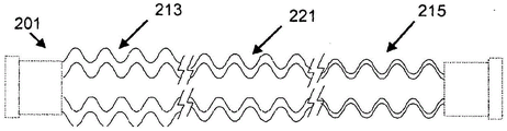
Referring again to fig. 2A, preferably, a first region 213 of the conduit 203 adjacent the first opening 205 is stiffer than a second region 215 of the conduit 203 adjacent the second opening 207. Various embodiments include one or more additional regions between the first region 213 and the second region 215 having a different hardness characteristic than the first region 213 and the second region 215 (e.g., a hardness characteristic intermediate the hardness characteristics of the first region 213 and the second region 215). For example, the three-zone tube 201 may impart a better bending profile than the two-zone tube 201. An exemplary three-zone tube 201 is shown in fig. 2B. This example includes a third region 221 intermediate the first region 213 and the second region 215.
The first region 213 and/or the second region 215 may be an absolute distance, such as 5cm or 10cm (or about 5cm or 10 cm). The first region 213 and/or the second region 215 may also represent relative distances. In at least one embodiment, the first region 213 comprises 10% -30% (or about 10% -30%), or 30% -50% (or about 30% -50%) of the total length of the tube 201 (where, for example, the total length of the tube 201 is the distance from the first opening 205 to the second opening 207 except for the ferrule (cuff) or connector 223 or any other separate end fitting attached to the end of the tube 201). For example, the first region 213 may comprise 33% (or about 33%), or 35% (or about 35%), of the total length of the tube 201 (where, for example, the total length of the tube 201 is the distance from the first opening 205 to the second opening 207). In at least one embodiment, the second region 215 comprises 5% -15% (or about 5% -15%), or 15% -50% (or about 15% -50%) of the total length of the tube 201 (where, for example, the total length of the tube 201 is the distance from the first opening 205 to the second opening 205). For example, the second region 215 thereof may comprise 10% (or about 10%), or 15% (or about 15%) of the total length of the tube 201 (where, for example, the total length of the tube 201 is the distance from the first opening 205 to the second opening 207). In at least one embodiment of a standard 1.8m tube 201, the first region 213 is 0.3m to 0.7m (or about 0.3m to 0.7m) and preferably 0.5m or near in length, the second region 215 is 0.1m to 0.2m (or about 0.1 to 0.2m) and preferably 1.15m or near in length, and the third region 221 intermediate the first region 213 and the second region 215 is between 1.0m to 1.5m and preferably 0.15m or near in length. In any case, the first region 213 and the second region 215 represent a substantial length of the tube 201.
The difference in stiffness in these regions represents a significant departure from the prior art. Typical prior art delivery tubes may incorporate extruded corrugated tubing. At extremely local levels, for example within a pitch of the corrugations, typically less than 1cm, the stiffness of the conduit will vary. The corrugation forming process may produce stiffer walls at the valleys of the corrugations than at the peaks. However, between the two ends of the tube connector, the stiffness characteristics across any substantial length are substantially the same as the characteristics of any other substantial length of the catheter. That is, these characteristics do not substantially change on a macroscopic level, as is the case in the embodiments described herein.
Certain embodiments include the following recognition: the stiffness of the first region 213 may be defined in terms of a "reflow length". As shown in fig. 3, when the tube 201 is engaged with the humidifier 107 or other source of humidified gas, the tube 201 is generally upright at the point of engagement. In other words, the slope of an imaginary line drawn through the center of the tube 201 is approximately infinite. Without some kind of bracket holding the tube 201 in this position, the flexibility of the tube 201 naturally causes it to bend at a distance from the joint. Thus, as the distance from the junction increases, the slope of an imaginary line passing through the center of the tube 201 gradually decreases. At a certain distance from the point of engagement, the slope of the imaginary line reaches zero. After this distance, the slope of the imaginary line becomes progressively more negative. When the slope of the phantom line is positive, condensate collected on the wall 211 of the tube surrounding the lumen 209 may theoretically "reflux" into the humidifier 107 under gravity. Conversely, when the slope of the phantom line is negative, the condensate will theoretically drain away from the humidifier 107.
Thus, for an unsupported tube 201, the return length 301 may be defined in terms of the distance between the point of connection to the humidifier 107 (or other humidity source) and the point when the slope of an imaginary line through the center of the tube 201 is zero. Generally, the backflow length 301 is the length of the tube 201 measured from the point of connection to the humidifier 107, wherein condensate collecting on the wall 211 surrounding the interior chamber 209 will naturally flow back into the humidifier 107. As the first region 213 becomes stiffer, the reflow length 301 increases. If the first region 213 is less stiff, the reflow length 301 decreases. In certain embodiments, the reflow length 301 is 350mm to 400mm (or about 350mm to 400mm), for example, 380mm (or about 380 mm). A study was conducted to evaluate the effect of hardness on the ability of the tube 201 to reflux condensate on the tube wall 211 into the humidifier 107. Tube 201 with the thicker cladding is connected to an AIRVO humidifier manufactured by Fisher & Paykel healthcare Inc. of Octland, New Zealand. The reflow length was measured as 380 mm. To eliminate the isolation effect of the cladding and to focus on the effect of the reflow length, a tube without cladding is used. A hob was used to replicate the 380mm reflow length in order to hold the tube in place. The AIRVO humidifier was then turned on and operated at a flow rate of 15L/min. The small desk fan was placed 40cm away from the humidifier outlet and turned on to the highest setting. This unrealistic ventilation condition is imposed to amplify possible condensation. At the distal end of the hob, the tube is allowed to assume a horizontal position resting on a table. The AIRVO humidifier and fan were kept running for 16 hours. After this time, the tube was removed from the AIRVO humidifier and the tube weighed.
By forming the tube 201 such that a greater length is oriented upwardly (or at least positively inclined) adjacent the humidified gases delivery means, condensate formed in this portion of the tube 201 flows back into the humidified gases delivery means. Certain embodiments include the following recognition: forming the tube 201 with a suitable return length 301 provides this upward extension while avoiding the need for bulky or complex rigid connectors. Referring again to fig. 2A, several characteristics may affect the stiffness of the catheter 203. For example, in at least one embodiment, the fact that the conduit 203 is stiffer adjacent the first opening 205 than it is adjacent the second opening 207 is caused by the wall 211 of the conduit 203 being thicker adjacent the first opening 205 than it is adjacent the second opening 207. Preferably, the first region 213 has an average wall 211 thickness of 0.5mm to 2.0mm (or about 0.5mm to 2.0mm), or 1.0mm to 2.0mm (or about 1.0mm to 2.0mm), or 1.1mm to 1.6mm (or about 1.1mm to 1.6mm), or 1.6mm (or about 1.6mm), or 1.58mm (or about 1.58mm), or 1.18mm (or about 1.18 mm). Preferably, the second region 215 has an average wall thickness of 0.1mm to 1.0mm (or about 0.1mm to 1.0mm), or 0.1mm to 0.7mm (or about 0.1mm to 0.7mm), or 0.1mm to 0.5mm (or about 0.1mm to 0.5mm), or 0.2mm to 0.7mm (or about 0.2mm to 0.7mm), or 0.3mm to 0.6mm (or about 0.3mm to 0.6mm), or 0.30mm (or about 0.30mm), 0.33mm (or about 0.33mm), 0.37mm (or about 0.37mm), 0.50mm (or about 0.50mm), 0.53mm (or about 0.53mm), 0.54mm (or about 0.54mm), or 0.56mm (or about 0.211 mm). A third region 211 intermediate the first region 213 and the second region 215 may have an average wall 211 thickness of 0.5mm to 1.0mm (or about 0.5mm to 1.0mm), preferably 0.6mm or thereabout. In certain embodiments, the average wall 211 thickness is at least 25% (or about 25%), at least 100% (or about 100%), or at least 200% (or about 200%) greater in the first region 213 than in the second region 215.
Another example measure of thickness is the average thickness per unit length. Preferably, the ratio of the average wall 211 thickness in the first region 213 to the average wall 211 thickness in the second region 221 per unit length is 1.5:1 to 5.5:1 (or about 1.5:1 to 5.5:1), or 4.5:1 to 5.0:1 (or about 4.5:1 to 5.0:1), or 2.0:2.5 (or about 2.0: 2.5). For the example bellows 201, this ratio can be 4.8:1 (or about 4.8:1) measured at the peaks and 2.2:1 (or about 2.2:1) measured at the valleys.
In at least one embodiment, the fact that the conduit 203 is stiffer adjacent the first opening 205 than it is adjacent the second opening 207 is caused by the wall 211 of the conduit 203 having a greater mass adjacent the first opening 207 than adjacent the second opening 207. The ratio of the average wall 211 mass in the first region 213 to the average wall 211 mass of the tubes 201 in the second region 215 per unit length may be 1.5:1 to 1.9:1 (or about 1.5:1 to 1.9:1), or 1.5:1 to 2:1 (or about 1.5:1 to 2: 1). The first region 213 may have an average wall 211 mass of 50g/m to 110g/m (or about 50g/m to 110g/m), or 65g/m to 100g/m (or about 65g/m to 100g/m), or 65g/m to 80g/m (or about 65g/m to 80g/m), or 70g/m (or about 70g/m), or 75g/m (or about 75 g/m). The second region 215 may have an average wall 211 mass of 20g/m to 50g/m (or about 20g/m to 50g/m), or 30g/m to 50g/m (or about 30g/m to 50g/m), or 30g/m to 45g/m (or about 30g/m to 45g/m), or 35g/m to 45g/m (or about 35g/m to 45g/m), or 40g/m (or about 40g/m), or 42g/m (or about 42 g/m). The third region 221 intermediate the first region 213 and the second region 215 may have an average wall 211 mass of 45g/m to 65g/m (or about 45g/m to 65g/m), preferably 50g/m or thereabout. In certain embodiments, the average wall 211 mass is at least 25% (or about 25%), at least 100% (or about 100%), or at least 200% (or about 200%) greater in the first region 213 than in the second region 215.
In at least one embodiment, the fact that the conduit 203 is stiffer adjacent the first opening 205 than it is adjacent the second opening 207 is caused by the wall 211 of the conduit 203 having a larger volume adjacent the first opening 207 than adjacent the second opening 207. The ratio of the average wall 211 volume in the first region 213 to the average wall 211 volume in the second region 215 per unit length may be 1.5:1 to 3.5:1 (or about 1.5:1 to 3.5:1), or 2.0:1 to 3.0:1 (or about 2.0:1 to 3.0:1), or 2.5:1 to 2.6:1 (or about 2.5:1 to 2.6: 1). The first region 213 mayHaving a width of 1.0cm3From/cm to 2.0cm3Per cm (or about 1.0 cm)3From/cm to 2.0cm3/cm), or 1.0cm3From/cm to 1.5cm3Per cm (or about 1.0 cm)3From/cm to 1.5cm3/cm), or 1.20cm3Per cm (or about 1.20 cm)3/cm), or 1.17cm3Per cm (or about 1.17 cm)3/cm) of the mean wall 211 volume. The second region 215 may have a 0.2cm3From/cm to 1.0cm3Per cm (or about 0.2 cm)3From/cm to 1.0cm3Per cm), or 0.40cm3From/cm to 0.55cm3Per cm (or about 0.40 cm)3From/cm to 0.55cm3Per cm), or 0.45cm3Per cm (or about 0.45 cm)3Per cm), or 0.50cm3Per cm (or about 0.50 cm)3/cm) of the mean wall 211 volume. In certain embodiments, the average wall 211 volume is at least 25% (or about 25%), at least 100% (or about 100%), or at least 200% (or about 200%) greater in the first region 213 than in the second region 215.
In at least one embodiment, the fact that the conduit 203 is stiffer adjacent the first opening 205 than it is adjacent the second opening 207 is caused by the wall 211 having a greater modulus of flexure adjacent the first opening 205 than adjacent the second opening 207.
Fig. 4A to 4E illustrate a test apparatus for measuring the flexural modulus of a pipe. The illustrated apparatus comprises a commercially available Instron machine.
As shown in fig. 4A, to test the tube 201, a plug 401 is inserted into the opening of the tube 201 sample.
As shown in fig. 4B, plug 401 is connected to arm 403 of test wheel 405. The tube 201 is wound on a test wheel 405 (which has a diameter of 78 mm) and held by a support wheel 407 having a diameter of 75 mm. The support wheels 407 contact the tube 201 to fix its position. It did not crush the tube 201 sample. The position of the support wheel 407 is adjusted accordingly by adjusting the position of the screw 409 along the slot 411 in the support frame 413 of the support wheel 407.
As shown in fig. 4C, a rope 415 is attached to the test wheel 405. From the point where the arm 403 of the test wheel 405 is adjacent the support wheel 407 and the tube 201 is in an undeflected condition, the string 415 is then pulled at a constant rate of 250mm per minute for a distance of 100 mm. The tensile load on the strand 415 is recorded as a function of distance.
The test is repeated with the tube 201 rotated about the tube axis (shown in fig. 4D and 4E) toward each of the four orientations to account for the asymmetry in the shape of the tube 201. Testing according to this procedure provides flexural characteristic data of the pipe 201. Testing a tube 201 having a flexural modulus that may be different at multiple locations along the tube 201 includes testing each region of the tube 201 by cutting out the region, installing the region, and testing according to this process.
For the section tested, the flexural modulus was calculated as the gradient of the linear portion of the load versus extension curve generated by the test. The flexural modulus of the test section is the average flexural modulus calculated for each of the four orientations. For example, FIG. 5A illustrates four orientations of flexural test data for a section of corrugated tubing having a tubing mass of 100 g/m; FIG. 5B illustrates four orientations of flexural test data for a section of corrugated tubing having a tubing mass of 40 g/m.
Fig. 5C illustrates only the linear portion of the curve of fig. 5A, with a best fit line for each orientation of the tube. The best fit line for the tube in the first orientation and has a gradient of 0.3377N/mm. The best fit line for the second oriented tube had a gradient of 0.3652N/mm. The best fit line for the tube in the third orientation has a gradient of 0.342N/mm. The best fit line for the tube oriented in the fourth position and having a gradient of 0.3506N/mm. The average gradient, and therefore the flexural modulus calculated from this test for this tube portion, was 0.3488N/mm.
FIG. 5D illustrates an enlarged portion of the curve in FIG. 5B, with a best fit line for each orientation of the tube. The best fit line for the tube in the first orientation has a gradient of 0.0208N/mm. The best fit line for the tube in the second orientation has a gradient of 0.0194N/mm. The best fit line for the tube in the third orientation has a gradient of 0.0076N/mm. The best fit line for the tube in the fourth orientation has a gradient of 0.0103N/mm. The average gradient, and therefore the flexural modulus calculated from this test for this tube portion, was 0.01452N/mm.
From these tests it can be seen that the part of the bellows having a tube mass of 40g/m has a test flexural modulus of about 0.015N/mm, whereas the part of the bellows having a tube mass of 100g/m has a test flexural modulus of 0.349N/mm. Thus, the flexural modulus of the 100g/m sample is more than 20 times that of the 40g/m tube.
As defined by the foregoing test methods, the ratio of the flexural modulus in the first region to the flexural modulus in the second region per unit length can be 10:1 to 250:1 (or about 10:1 to 250:1), 100:1 to 220:1 (or about 100:1 to 220:1), or 170:1 to 200:1 (or about 170:1 to 200:1), or 188:1 (or about 188:1), or 185:1 (or about 185: 1). In certain embodiments, the average flexural modulus is at least 25% (or about 25%), at least 100%, or at least 200% greater in the first region than in the second region.
Wall composition
In at least one embodiment, the wall is formed from an extrudate comprising one or more polymers. Preferred polymers include Linear Low Density Polyethylene (LLDPE), Low Density Polyethylene (LDPE), polypropylene (PP), polyolefin plastic (POP), Ethylene Vinyl Acetate (EVA), plasticized polyvinyl chloride (PVC), or blends of two or more of these materials. The polymer forms a weight percent (wt%) of at least 98.4 (or about 98.4), 98.5 (or about 98.5), 98.6 (or about 98.6), 98.7 (or about 98.7), 98.8 (or about 98.8), 98.9 (or about 98.9), 99.0 (or about 99.0), 99.1 (or about 99.1), 99.2 (or about 99.2), 99.3 (or about 99.3), 99.4 (or about 99.4), 99.5 (or about 99.5), 99.6 (or about 99.6), 99.7 (or about 99.7), 99.8 (or about 99.8), or 99.9 (or about 99.9) of the total extrudate. In particular embodiments, the extrudate comprises 99.488 (or about 99.488) wt% or about 99.49 (or about 99.49) wt% LLDPE.
The extrudate may also optionally include one or more surface modifiers. Surface modifiers are additives that affect the properties of the surface of a material, either alone or in combination with another substance. This agent can help increase the surface energy (or wettability) of the wall surface. Increasing the surface energy may advantageously promote a reduced contact angle between droplets or beads of condensate or liquid that may accumulate on the surface. Rather, the droplets or beads can spread over a larger surface area of the wall and, therefore, are more likely to re-evaporate into the airflow flowing through the lumen.
It may be particularly advantageous to include a surface modifier in the bellows. In a bellows, small droplets or globules of condensate are more likely to form in the parts of the corrugation at the cold spots. The cryogenic location is typically the portion of the corrugation that is closest to or most exposed to the ambient conditions surrounding the pipe. Changing the surface characteristics of the pipe wall can cause droplets or globules of water that form at cryogenic locations to spread across the pipe surface and, as the process proceeds, move toward warmer temperature regions. This migration of movement of droplets or globules can achieve an increased rate of re-evaporation as droplets move towards warmer areas and towards areas of the tube exposed to greater or faster gas flow.
Suitable surface modifying agents include Glycerol Monostearate (GMS), ethoxylated amines, sodium alkyl sulfonate salts, and lauric diethanolamide, as well as additives including these. MLDNA-418 supplied by Clariant (New Zealand) Co., Ltd and having a product name of "418 LD antistatic masterbatch" is a surface modifier masterbatch in which 5 (+ -0.25)% of glyceryl monostearate (CAS number 123-94-4) is used as an active ingredient. Preferably, the surface modifier comprises at least about 0.05 (or about 0.05), 0.1 (or about 0.1), 0.15 (or about 0.15), 0.2 (or about 0.2), 0.25 (or about 0.25), 0.3 (or about 0.3), 0.35 (or about 0.35), 0.4 (or about 0.4), 0.45 (or about 0.45), 0.5 (or about 0.5), 1.1 (or about 1.1), 1.2 (or about 1.2), 1.3 (or about 1.3), 1.4 (or about 1.4), or 1.5 (or about 1.5) weight percent of the total extrudate. For example, in at least one embodiment, the extrudate comprises 0.25 wt% (or about 0.25 wt%) of the surface modifying agent. As another example, in at least one embodiment, the extrudate includes 0.5 wt% (or about 0.5 wt%) of the surface modifying agent.
Other methods may also be used to increase the surface energy and reduce the contact angle. Suitable methods include physical, chemical, and radiation methods. Physical methods include, for example, physical adsorption and langmuir-blodgett membranes. Chemical methods include oxidation by strong acids, ozone treatment, chemisorption, and flame treatment. Irradiation methods include plasma (glow discharge), corona discharge, photo-activation (UV), laser, ion beam, electron beam, and gamma irradiation.
By selecting a suitable surface modification method or surface modifier, it is possible to provide a conduit wall having a surface property contact angle of less than 50 (or about 50), 45 (or about 45), 40 (or about 40), 35 (or about 35), 30 (or about 30), 25 (or about 25), 20 (or about 20) degrees (°), as measurable by an angle measuring device (e.g., goniometer). For example, a tube wall having a surface characteristic contact angle of less than 35 ° (or about 35 °) provides useful results.
Table 1 below shows contact angle measurements for different LLDPE samples, including samples treated with a surface modifier and samples treated with radiation. The contact angle measurement is based on a static droplet shape test method performed according to ASTM standard D7334, 2008, "standard practice for surface wettability of coatings, substrates and pigments by advancing contact angle measurement".
TABLE 1

The samples with 5% MLDNA-418 surface modifier produced the lowest measured contact angle compared to the other surface modification methods tested.
Foam
In certain embodiments, the tube wall described above may be formed from a polymer foam. A foam is a solid material having gas voids dispersed throughout the foam. The voids may be open-celled or reticulated (such that a majority (e.g., 51% -100%) of the voids are interconnected with other voids). The voids may also be closed cell such that a majority (e.g., 80%, 90%, or more) of the cells are not interconnected with other voids. Foams with open-cell voids can be advantageous because they are generally sparser, require less material, and are therefore less expensive to produce than closed-cell voids. Preferably, however, the voids are closed cell, which improves and better controls the insulating properties of the wall. Foams with closed cell voids may have the additional advantage of being easier to manufacture than foams with open cell voids.
In embodiments including a foam wall, the foam wall is preferably a monolithic polymer foam, e.g., formed from extrusion of a single extrudate.
The foam wall may advantageously provide an improved level of thermal insulation for the internal cavity compared to the level of thermal insulation provided by a non-foam wall. Thus, in at least one embodiment, the wall insulates the contents of the elongated conduit (e.g., humidified gas flowing through the gas flow passage, etc.) from possible cooling effects of the environment surrounding the medical tube (e.g., from ambient air surrounding the breathing circuit, or laparoscopic insufflation system). The environment surrounding the medical tube is, for example, a hospital ward or room, an operating room, a home bedroom, or other location where the patient may be located.
In various embodiments, the foam wall has or provides a thermal conductivity of 0.2W/m-K to 0.4W/m-K (or about 0.2W/m-K to 0.4W/m-K). However, it should be appreciated that other levels of thermal conductivity may be beneficially achieved by the foam wall, and thermal conductivities of 0.15W/m-K to 0.35W/m-K (or about 0.15 to 0.35W/m-K) or 0.25W/m-K to 0.45W/m-K (W/m-K) are also contemplated.
An example method for forming the foam wall includes adding a chemical blowing agent to the extrudate. Chemical blowing agents are sometimes also referred to as blowing agents. The chemical blowing agent allows for the foaming of the extrudate material as part of or after the extrusion process, which is described in more detail below. The chemical blowing agent may comprise at least 0.005 (or about 0.005), 0.006 (or about 0.006), 0.007 (or about 0.007), 0.008 (or about 0.008), 0.009 (or about 0.009), 0.01 (or about 0.10), 0.011 (or about 0.011), 0.012 (or about 0.012), 0.013 (or about 0.013), 0.014 (or about 0.014), 0.015 (or about 0.015), 0.016 (or about 0.016), 0.017 (or about 0.017), 0.018 (or about 0.018), 0.019 (or about 0.019), or 0.02 (or about 0.02) weight percent of the total extrudate. For example, the chemical blowing agent may comprise 0.01 to 0.012 (or about 0.01 to 0.012) weight percent of the total extrudate. As part of the chemical foaming extrusion process, the polymer component of the extrudate is mixed with a chemical blowing agent. Some preferred chemical foaming agents include calcium oxide. For example, MHYNA-CF20E, available under the product name Hydrocerol CF20E from Clariant, N.C., is a chemical blowing agent in the form of a blowing agent masterbatch having from about 0.5% to 1% calcium oxide as the active ingredient.
During the chemical foam extrusion process, the polymeric resin component and the chemical blowing agent are mixed and melted. Chemical blowing agents decompose and release a gas that is dispersed in the polymer (or masterbatch or extrudate) melt and expands after exiting the die of the extruder.
It will also be appreciated that other foaming techniques may be used to form the foam wall, for example by physical rather than chemical foaming methods. Physical foaming methods include introducing a gas directly into the extrudate while under pressure. As the extrudate is extruded, the pressure decreases, causing the gas to expand. For example, one such physical foaming technique involves foaming or injecting a gas into the extrudate at or near the point of extrusion. Such gases may include nitrogen, carbon dioxide, pentane or butane.
Protective sleeve
In certain embodiments, the elongate catheter 203 can further comprise a sheath 227, as shown in fig. 2C. The sheath 227 is a member that partially or completely surrounds the wall 211. The sheath 225 may be secured to the wall 211 of the catheter 203 at a location along the wall 211 or may be secured only to the end of the tube 201. The sheath 227 may be used to secure conductive filaments (described below) in place and/or prevent heat loss due to cold air flow impinging on the tube wall 211.
While the sheath 227 may be incorporated into a catheter 203 that includes a smooth wall (not shown) or a corrugated wall 211, it may be particularly advantageous to include this sheath 227 with the corrugated wall. The sheath may trap air between adjacent external peaks (or annular protrusions) of the corrugations. This may help to further isolate the gas passing through the lumen 209.
For delivery tubes incorporating sheath 227, sheath 227 may be applied around wall 211 as an extruded outer layer, as a wrapping around wall 211, or as a sleeve that is slid or pulled into place around wall 211. This jacket 227 may be formed of a similar material to the wall 211 (described above), such as LLDPE. The jacket 227 may help to further improve the thermal performance of the tube 201.
However, the average thickness per unit length, average mass per unit length, average volume per unit length, or flexural modulus may vary on a macroscopic level along the length of the sheath 227. In some embodiments, the property measurement may be greater at one region of the sheath 227 adjacent one end of the tube 201 than at one region of the sheath 227 adjacent the other end. In other embodiments, the property measurements may vary gradually along the length of the sheath 227. In other embodiments, the property measurements may have distinct transitions that move along the length of the sheath 227. In certain embodiments, the measurement or characteristic may be greater at a region adjacent one end of the tube 201 than at a mid-length portion of the tube 201, and may be greater at a region adjacent the other end of the tube 201 than at a mid-portion of the tube 201.
For example, the outer sheath 227 may be thicker at the humidifier end of the tube 201 to better insulate the tube 201 and prevent heat loss where most condensation is likely to occur. The thicker sheath 227 at the humidifier end may also increase the stiffness of the tube 201 such that it maintains a more vertical position over a greater distance before bending towards horizontal, thereby increasing the reflux length (not shown). In this way, more condensation is returned to the humidifier (not shown) rather than into the breathing tube 201. A thinner sheath 227 at the patient end may increase flexibility and reduce mass to improve user comfort.
When the jacket 227 is extruded around the wall 211, this extrusion may be, for example, a continuous step of the initial extrusion of the wall 211, that is, a post-formation extrusion step of the wall 211. Further, when the outer sheath 227 is, for example, a wrap around the wall 211, the sheath 227 is constructed in place from a tape or ribbon that is wound in a helical manner around the length of the wall 211. Again, when the outer sheath 227 is preformed as a hollow tube, it may be nested in position around the outside of the wall 211.
Conductive filament
In certain embodiments, the tube 201 may further include one or more conductive filaments. These conductive filaments may be heating filaments and/or sensing filaments.
The filaments may, for example, take the form of wires or ribbons on or in the wall of the catheter. Fig. 6 illustrates an example placement of a heater wire 601 within the lumen 209 of the tube 201. Although the filaments may be within the lumen 209, it may also be desirable to move the filaments out of the airflow path. For example, the filaments may be placed on or within a wall radially opposite the lumen. Fig. 7 illustrates the placement of heater wire 601 around the exterior surface of wall 211. Such placement may reduce the risk of ignition in the oxygen-rich gas stream and also improve the laminar gas stream.
The material of such filaments is a conductive metal comprising copper or aluminum, or a PTC (positive temperature coefficient) type material. Aluminum is less conductive than copper, but can be an economical choice, except that its wire diameter is larger at the same resistance. Although the applied loop voltage is intrinsically safe (less than 50V), the wire will ideally be self-insulating, either by enamel coating, or by anodization in the case of aluminum, for corrosion resistance and electrical safety in the event of damage to the wall or sheath.
In certain embodiments, the filaments may be placed on the outer surface of the wall 211 (radially outward from the lumen 209) and a plastic sheath 227 may be installed around the filaments. In this configuration, the sheath 227 may help to restrain the filaments in place. Additionally, a sheath may also be included when the filaments are placed in the lumen 209 or in the wall 211. As explained above, the insulating outer jacket 227 prevents heat loss. However, an outer sheath 227, whether or not a filament is also included, may be employed.
Comparison with a pipe of uniform hardness
FIG. 8 compares the condensate accumulation in the uniform durometer tube to the condensate accumulation in the variable durometer tube. In this experiment, three uniform durometer tubes and one variable durometer tube were connected in a circuit with a source of humidified gas and placed in a test chamber with a flow of cold air, simulating a typical hospital room with conditioned air flowing through the circuit. The condensate that accumulated over a 16 hour period was collected and weighed. The results indicate that increasing the mass of the wall in a uniform thickness tube from 50g/m to 63g/m to 74g/m reduces condensate accumulation. A variable durometer tube made from three sections with a mass of 74g/m at a first end, 63g/m in the middle region, and 50g/m at a second end unexpectedly accumulated less condensate than a 74g/m tube.
One explanation for the unexpected improvement in performance of the variable durometer tube over the hardest uniform thickness tube may be the interaction with the humidifier acting as a source of humidified gas. An MR850 humidifier manufactured by Fisher & Paykel healthcare limited, auckland, new zealand, senses the patient end temperature and controls the heater plate under the chamber and the heating filament in the tube. The algorithm used by the humidifier involves placing the gas in the tube at 37 ℃ to fully saturate it and then heating the tube so that the temperature sensed at the end of the tube measures 40 ℃. Because the 50/63/74g/m variable stiffness tube has a relatively thin wall at the patient end, the temperature is lower at the patient end than it is at the patient end of a 74g/m uniform wall tube. Thus, the control algorithm of the humidifier places more power into the heater plate and heating filament with the variable durometer sample, resulting in less condensation at the humidifier end of the tube.
Component in a medical circuit
Referring next to fig. 9, an example medical circuit is illustrated in accordance with at least one embodiment. The circuit comprises a variable stiffness tube for the aspirator tube 103 as described above. The characteristics of the aspirator tube 103 are similar to the tubes described above. The inspiratory tube 103 has an inlet 109 in communication with a source of humidified gas 115, and an outlet 113 through which humidified gas is provided to the patient 101. As described above, heater wire 601 may be placed within air intake duct 103 to reduce the risk of rain condensation in the duct by maintaining the duct wall temperature above the dew point temperature.
In fig. 9, an exhalation tube 117 is also provided. The exhalation tube 117 also has an inlet 109 that receives exhaled humidified gas from the patient and an outlet 113. As described above with respect to fig. 1, the outlet 113 of the exhalation tube 117 may discharge exhaled gas into the atmosphere, into the ventilator/blower unit 115, into an air scrubber/filter (not shown), or into any other suitable location.
However, the exhalation tube is optional. The inspiratory tube 103 according to the embodiments described above may be used with other forms of respiratory supports, for example, using a stand-alone blower humidifier without an expiratory return path. Examples of such products include the humidifying CPAP delivery product and COPD treatment product of Fisher & Paykel healthcare limited, new zealand, kland. In these systems, a combined blower/humidifier supplies humidified gas to a connected delivery tube. The delivery tube supplies these gases to a patient interface connected to the patient end of the delivery tube. The patient interface is typically a full face mask for CPAP treatment, a nasal mask, a nasal pillow, a nasal prong or cannula for COPD treatment, or a tracheal connector of the intubated patient, wherein the device may be used to facilitate the transition of full ventilation.
Component of an insufflation system
Laparoscopic surgery, also known as Minimally Invasive Surgery (MIS) or keyhole surgery, is a modern surgical technique in which operations in the abdomen are performed through a small incision (typically 0.5cm to 1.5cm) compared to the larger incision required in traditional surgical procedures. Laparoscopic surgery involves manipulation within the abdominal or pelvic cavity. During laparoscopic surgery with insufflation, an insufflation gas (typically CO) may be desirable2) Humidified before being passed into the abdominal cavity. This may help prevent "dehydration" of the patient's internal organs, and may reduce the amount of time required for post-operative recovery. Insufflation systems typically include a plurality of humidifier chambers that hold a quantity of water therein. Humidifiers generally include a heater plate that heats water to produce water vapor that is delivered to incoming gases to humidify the gases. This gas with water vapor is delivered out of the humidifier.
Referring next to FIG. 10, an insufflation system 1001 in accordance with at least one embodiment is illustrated. Insufflation system 1001 includes an insufflator 1003 which generates a flow of insufflation gas at a pressure above atmosphere for delivery into the abdominal or peritoneal cavity of patient 1005. The gases are delivered to the humidifier 1007 (comprising the heater base 1009 and the humidifier chamber 1011) where the chamber 1011 is in contact with the heater base 1009 in use, so that the heater base 1009 provides heat to the chamber 1011. In the humidifier 1007, the insufflation gas is passed through a chamber 1011 so that the insufflation gas is humidified to the appropriate moisture level.
The system 1001 includes a delivery conduit 1013 connected between a humidifier chamber 1011 and a peritoneal cavity or surgical site of a patient 1005. The conduit 1013 is a variable stiffness tube as described above. The conduit 1013 has a first end and a second end, the first end being connected to the outlet of the humidifier chamber 1011 and receiving humidified gas from the chamber 1011. The second end of the conduit 1013 is placed in the surgical site or peritoneal cavity of the patient 1005 and humidified insufflation gas travels from the chamber 1011, through the conduit 1013 and into the surgical site to insufflate and inflate the surgical site or peritoneal cavity. The system also includes a controller (not shown) that adjusts the amount of humidity supplied to the gas by controlling the power supplied to the heater substrate 1009. The controller may also be used to monitor the water in the humidifier chamber 1011. A smoke evacuation system 1015 is shown leading out of the body cavity of the patient 1005.
The smoke evacuation system 1015 may be used in conjunction with the air blowing system 1001 described above, or may be used with other suitable air blowing systems. The smoke evacuation system 1015 includes a discharge or exhaust branch 1017, a discharge assembly 1019, and a filter 1021. The drain branch 1017 is connected between the filter 1021 and a drain assembly 1019 which, in use, is located in or adjacent to the surgical site or peritoneal cavity of the patient 1005. The discharge branch 1017 is a self-supporting tube (that is, the tube is capable of supporting its own mass without collapsing) with two open ends: a surgical site end and an exit end.
At least one embodiment includes the following recognition: the use of a variable durometer tubing as conduit 1013 may deliver humidified gas to a patient 1005 surgical site with minimal heat loss. This may advantageously reduce the overall energy consumption in the insufflation system, as less heat input is required to compensate for heat losses.
Manufacturing method
The catheter, sheath, or both of the delivery tube may be manufactured according to a number of processes adapted to provide the stiffness variation in the tube. The catheter and sheath may be formed by the same manufacturing method, or by different manufacturing methods. In some manufacturing methods, the tube and sheath may be integrated during the manufacturing method such that the sheath is connected to the catheter at a number of locations along the length of the tube or along one continuous spiral along the length of the tube. Alternatively, the sheath may freely surround the catheter and connect the catheter only at or adjacent the end connector.
Typically, the catheter, sheath, or both may be made of one or more extruded polymer components. The characteristics of the extrudate (including ingredients, surface modifiers, methods for increasing surface energy, and blowing agents) are described above.
A first manufacturing method is described with reference to fig. 11. The method includes extruding an elongated catheter having a longitudinal axis, a lumen extending along the longitudinal axis, and a wall surrounding the lumen, wherein the wall is stiffer in a first length of the catheter than in a second length of the catheter. The method may further comprise corrugating the elongate conduit, for example using a corrugating die. More specifically, the process involves mixing or providing a masterbatch of extrudate material (i.e., material for extrusion), feeding the masterbatch into an extrusion die, extruding the extrudate as described above, and (optionally) feeding an elongated conduit into a corrugator using an endless chain of die blocks to form a corrugated tube.
Fig. 11 generally illustrates an arrangement in which a feed hopper 1101 for receiving raw ingredients or materials (e.g., masterbatch and other materials) is provided that will be passed through a screw feeder 1103 driven by a motor 1105 in a direction a toward a die head 1107. Melt tube 1109 is extruded from die 1111. The conductive filaments may optionally be co-extruded on or in a melt tube 1109. The method may further comprise one or more screw extrusion processes which progressively increase the layer of material to produce sections of different hardness along the tube. Such a screw extrusion process is described in more detail below.
Extruders, such as the Welex (Welex) extruder equipped with 30mm to 40mm diameter screws and typically having a 12mm to 16mm annular die with 0.5mm to 1.0mm clearance, have been found suitable for the rapid production of low cost tubes. Similar extrusion machines are available from the american house (Kuhne) (germany), AXON AB plastics machinery (sweden), AMUT (italy), and Battenfeld (germany and china). Have been found, for example, to consist of Corrugator machines such as the corrugator machines manufactured and supplied (hasford, germany) are suitable for the corrugation forming step. Similar machines are available from OLMAS (california, italy), huakusu machinery manufacturing limited (celadon, china), or tuypro industry (achievement) limited (achievements, china).
During manufacture, the melt tube 1109 is transferred between a series of rotating dies/blocks on a corrugator after exiting extruder die 1111 and forms a corrugated tube. The molten tube is formed by vacuum applied to the outside of the tube via slots and channels through the blocks and/or pressure applied to the inside of the tube via an air channel through the center of the extruder die core. If internal pressure is applied, a specially shaped long internal rod extending from the die core pin and closely conforming to the inside of the corrugations may be required to prevent air pressure from escaping along the tube at both ends. The corrugator speed can be varied to achieve different wall thicknesses. Slower corrugator speeds give thicker walls and faster speeds give thinner walls.
The tube may also include a flat cuff region for connection to an end connector fitting. Thus, during manufacture, the molded plastic end connector fitting may be permanently affixed and/or hermetically sealed by friction fit, adhesive bonding, overmolding, or by thermal or ultrasonic welding.
Another suitable method for manufacturing a tube according to embodiments described herein involves spiral forming, as shown in fig. 12. Generally, the method includes extruding a strip of adhesive tape, wherein a first length of the tape is stiffer than a second length of the tape; the extruded strip is helically wound around the mandrel such that adjacent turns of the extruded strip touch or overlap, thereby forming an elongate catheter having a longitudinal axis, a lumen extending along the longitudinal axis, and a wall surrounding the lumen, wherein the wall is stiffer in a first length of the catheter than in a second length of the catheter. The method may further comprise optionally corrugating the elongate conduit.
The extrusion process involves mixing or providing a masterbatch of extrudate material (i.e., material for extrusion), feeding the masterbatch into an extrusion die, extruding the extrudate into a strip.
Subsequently, the extruded or preformed tape is wound into a spiral such that within each turn one edge of the tape overlaps over an edge of the previous turn and under an edge of the subsequent turn. Such helically wound catheters may be made using a single helically disposed ribbon or a plurality of helically disposed ribbons that are interleaved. In some embodiments, a reinforcing strip overlies the overlap between the turns of the strip. The strip may provide helical reinforcement of the tube against crushing and may also provide a source of thermal, chemical or mechanical adhesive for fusing or joining the overlapping portions of the tape. In some examples, a double walled pipe may be constructed by placing additional strips, or portions of the same strip, on the outside and supported on helical ridges formed by the strips.
In this method, the hardness of the tube depends on the hardness of the belt, and the hardness of the tube can be adjusted by changing the thickness, mass, volume, flexural modulus, and the like of the belt. A tube having a variable wall thickness along the length of the tube may be constructed according to this process by varying the thickness of the band such that, for example, in a first region, the band may have a greater thickness than in another region, where the thickness may be somewhat thinner, and in a second region the thickness may be thinner.
Another suitable method for spiral forming includes extruding a strip having a generally uniform stiffness; the extruded strip is helically wound around the mandrel such that adjacent turns of the extruded strip touch or overlap, thereby forming an elongate catheter having a longitudinal axis, a lumen extending along the longitudinal axis, and a wall surrounding the lumen, wherein the wall is stiffer in a first length of the catheter than in a second length of the catheter. The method may include corrugating an elongate conduit to provide a conduit with a wall of variable stiffness. For example, the corrugator speed may be varied to achieve different wall thicknesses. Slower corrugator speeds give thicker walls and faster speeds give thinner walls.
A melt extruded tube 1201 is shown in fig. 12 exiting the die 1203 of the extruder before passing into the corrugator 1205. Upon exiting corrugator 1205, heater wire 601 is wound around the outside of formed tubular member 201.
One advantage of the preferred type of tube manufacture described above with reference to fig. 12 is that some of the die blocks B may include end ferrule features that are simultaneously formed into the tubular member 201. Manufacturing speed can be significantly increased by complexity reduction and elimination of secondary manufacturing processes. While this method is an improvement over the individual cuff formation process, a disadvantage of the prior art flat cuffs is that the corrugator must be slowed down to increase the wall thickness of the tube in this region (the extruder continues at the same speed). The ferrule thickness is increased to achieve increased ferrule strength and sealing characteristics with the ferrule adapter fitting. Furthermore, during the limited contact time with the corrugator block, the heat of the molten polymer in this thicker region is difficult to remove and this can become an important limiting factor for the maximum operating speed of the pipe line.
The foregoing description of the invention includes preferred forms thereof. Modifications may be made thereto without departing from the scope of the invention. To those skilled in the art to which the invention relates, many changes in construction and widely differing embodiments and applications of the invention will suggest themselves without departing from the scope of the invention as defined in the appended claims. The disclosures and the descriptions herein are purely illustrative and are not intended to be in any sense limiting.
Claims (25)
1. A medical tube for providing humidified gas to a patient, the medical tube comprising:
a humidifier end sized and shaped to be connected to a source of humidification gas;
a patient end sized and shaped to connect to a patient interface;
wherein the tube wall has an increased thickness, mass, and/or volume at the humidifier end of the medical tube to include greater thermal insulation or better isolate heat loss than at the patient end of the medical tube.
2. A medical tube for providing humidified gas to a patient, the medical tube comprising:
a humidifier end sized and shaped to be connected to a source of humidification gas;
a patient end sized and shaped to connect to a patient interface;
wherein the humidifier end tube wall has an increased thickness, mass and/or volume to isolate the medical tube from heat loss at the location where most condensation occurs.
3. The medical tube of claim 1 or 2, wherein the increased thickness, mass and/or volume is on a per unit length basis.
4. The medical tube of claim 2, wherein the increased thickness, mass, and/or volume of the humidifier end is relative to the patient end.
5. The medical tube of claim 2, wherein the increased thickness, mass, and/or volume of the humidifier end is located in a region adjacent to the humidifier end.
6. A medical tube, comprising:
an elongated catheter having a first opening, a second opening, a longitudinal axis, a lumen extending along the longitudinal axis between the first and second openings, and a tube wall extending between the first and second openings and surrounding the lumen and formed of an extruded material;
wherein the tube wall has an increased thickness, mass and/or volume in a first region of the tube adjacent the first opening so as to comprise greater insulation or better insulate heat loss in the first region of the tube adjacent the first opening than in a second region of the tube adjacent the second opening.
7. The medical tube of claim 6, wherein the first opening is sized and shaped to connect to a source of humidified gas.
8. The medical tube of claim 6 or 7, wherein the second opening is sized and shaped to connect to a patient interface.
9. The medical tube of claim 6, wherein the extruded material is foam.
10. The medical tube of claim 9, wherein the foam is a closed cell foam.
11. The medical tube of claim 6, wherein the extruded material comprises one or more surface modifiers.
12. The medical tube of claim 1, 2 or 6, further comprising a sheath surrounding at least a portion of an outer surface of the medical tube.
13. The medical tube of claim 12, wherein the sheath comprises an extruded material extruded around at least a portion of an outer surface of the medical tube.
14. The medical tube of claim 12, wherein the sheath comprises a material generally helically wrapped around at least a portion of the outer surface of the elongate catheter.
15. The medical tube of claim 12, wherein the sheath comprises a lining material that is disposed around at least a portion of an outer surface of the medical tube.
16. The medical tube of claim 12, wherein the sheath comprises a sheath wall having a generally constant stiffness.
17. The medical tube of claim 12 wherein the sheath includes a sheath wall, the sheath wall being stiffer in a first region of the sheath than in a second region of the sheath.
18. The medical tube of claim 12 wherein the sheath wall is stiffer proximate the first opening of the medical tube than proximate the second opening of the medical tube.
19. The medical tube of claim 12 wherein the sheath wall is stiffer proximate the second opening of the medical tube than proximate the first opening of the medical tube.
20. The medical tube of claim 12 wherein the sheath wall is stiffer proximate the medical tube first and second openings than in the catheter intermediate region.
21. The medical tube of claim 1, 2 or 6, further comprising one or more conductive filaments in or on the medical tube.
22. The medical tube of claim 21, wherein at least one of the one or more conductive filaments is a heating wire.
23. The medical tube of claim 21, wherein at least one of the one or more conductive filaments is a sensing filament.
24. An exhalation tube, comprising:
an inlet configured to receive exhaled humidified gases from a patient;
an outlet configured to discharge exhaled gas to one or more of: atmospheric, ventilator/blower units, air scrubbers/filters, other ancillary equipment, any other suitable location;
wherein the duct wall has an increased thickness, mass and/or volume at the inlet of the exhalation duct to include greater thermal insulation or better isolate heat losses than at the outlet of the exhalation duct.
25. An exhalation tube, comprising:
an inlet configured to receive exhaled humidified gases from a patient;
an outlet configured to discharge exhaled gas to one or more of: atmospheric air, ventilator/blower units, air scrubbers/filters, other ancillary equipment, any other suitable location;
wherein the duct wall has an increased thickness, mass and/or volume at said inlet so as to isolate the expiratory duct from heat losses where most of the condensation occurs.
Applications Claiming Priority (4)
| Application Number | Priority Date | Filing Date | Title |
|---|---|---|---|
| US201161547482P | 2011-10-14 | 2011-10-14 | |
| US61/547,482 | 2011-10-14 | ||
| PCT/NZ2012/000184 WO2013055235A1 (en) | 2011-10-14 | 2012-10-12 | Medical tubes and methods of manufacture |
| CN201280058622.9A CN103987420B (en) | 2011-10-14 | 2012-10-12 | Medical tube and manufacturing method |
Related Parent Applications (1)
| Application Number | Title | Priority Date | Filing Date |
|---|---|---|---|
| CN201280058622.9A Division CN103987420B (en) | 2011-10-14 | 2012-10-12 | Medical tube and manufacturing method |
Publications (2)
| Publication Number | Publication Date |
|---|---|
| CN109045433A CN109045433A (en) | 2018-12-21 |
| CN109045433B true CN109045433B (en) | 2022-07-08 |
Family
ID=48082144
Family Applications (4)
| Application Number | Title | Priority Date | Filing Date |
|---|---|---|---|
| CN201811053334.XA Active CN108992757B (en) | 2011-10-14 | 2012-10-12 | Medical tube and method of manufacture |
| CN202210728125.0A Pending CN115105707A (en) | 2011-10-14 | 2012-10-12 | Medical tube and method of manufacture |
| CN201811053333.5A Active CN109045433B (en) | 2011-10-14 | 2012-10-12 | Medical tube and method of manufacture |
| CN201280058622.9A Active CN103987420B (en) | 2011-10-14 | 2012-10-12 | Medical tube and manufacturing method |
Family Applications Before (2)
| Application Number | Title | Priority Date | Filing Date |
|---|---|---|---|
| CN201811053334.XA Active CN108992757B (en) | 2011-10-14 | 2012-10-12 | Medical tube and method of manufacture |
| CN202210728125.0A Pending CN115105707A (en) | 2011-10-14 | 2012-10-12 | Medical tube and method of manufacture |
Family Applications After (1)
| Application Number | Title | Priority Date | Filing Date |
|---|---|---|---|
| CN201280058622.9A Active CN103987420B (en) | 2011-10-14 | 2012-10-12 | Medical tube and manufacturing method |
Country Status (7)
| Country | Link |
|---|---|
| US (2) | US10828455B2 (en) |
| EP (2) | EP2766079B1 (en) |
| JP (4) | JP6357101B2 (en) |
| CN (4) | CN108992757B (en) |
| AU (4) | AU2012321401B2 (en) |
| CA (4) | CA3086533A1 (en) |
| WO (1) | WO2013055235A1 (en) |
Families Citing this family (18)
| Publication number | Priority date | Publication date | Assignee | Title |
|---|---|---|---|---|
| AU2003244171B2 (en) | 2002-09-09 | 2007-11-15 | Fisher & Paykel Healthcare Limited | Limb for Breathing Circuit |
| WO2013156914A2 (en) * | 2012-04-17 | 2013-10-24 | Koninklijke Philips N.V. | Gas delivery conduit for a respiratory therapy system |
| EP2657418B1 (en) * | 2012-04-26 | 2015-01-14 | Airbus Operations GmbH | Noise reduction unit for vacuum suction drains |
| CN109550130B (en) * | 2012-12-04 | 2023-02-03 | 费雪派克医疗保健有限公司 | Medical tube and method for manufacturing same |
| DE202013103243U1 (en) * | 2013-07-19 | 2014-10-20 | Rehau Ag + Co | Media line, in particular for transporting a urea-water solution |
| US10953185B2 (en) * | 2017-03-31 | 2021-03-23 | Koninklijke Philips N.V. | Moisture wicking conduit and system |
| CN110997049A (en) * | 2017-05-26 | 2020-04-10 | 费雪派克医疗保健有限公司 | Flexible mixed medical tube for neonate |
| GB2569802B (en) * | 2017-12-22 | 2021-12-15 | Intersurgical Ag | Medical tubing |
| AU2019211028A1 (en) * | 2018-01-24 | 2020-09-10 | Fisher & Paykel Healthcare Limited | Medical tubes for breathing circuit |
| EP3809914A4 (en) * | 2018-06-25 | 2022-04-20 | Booker Holdings, LLC | Surface energy enhancing fluid and applications on living tissues |
| USD958968S1 (en) | 2018-11-28 | 2022-07-26 | Fisher & Paykel Healthcare Limited | Breathing tube with mesh |
| EP3817799A4 (en) * | 2019-02-15 | 2022-05-18 | Vincent Medical (Dong Guan) Manufacturing Co., Ltd. | A breathing circuit having an embedded heating wire and temperature sensor |
| CN110433376A (en) * | 2019-08-09 | 2019-11-12 | 贾凌 | A kind of temperature regulating device of air flue humidification atomizer pipeline |
| CA3163675A1 (en) * | 2020-01-08 | 2021-07-15 | Owen GIESBRECHT | Cleanable respiratory circuit |
| EP3861945A1 (en) * | 2020-02-07 | 2021-08-11 | Gyrus ACMI, Inc. d/b/a Olympus Surgical Technologies America | Medical device including flexible shaft with multiple bearings |
| US20220241568A1 (en) * | 2020-09-10 | 2022-08-04 | Gerard V. Sunnen | Integrated portable apparatus for topical wound therapy, using ambient air for the creation of three bioactive gases that independently and synergistically assist in the resolution of pathogenic dermatological conditions |
| JP2022154079A (en) * | 2021-03-30 | 2022-10-13 | 福展美科技有限公司 | Medical tube for use with user interface in respiratory therapy |
| WO2022246520A1 (en) * | 2021-05-28 | 2022-12-01 | ResMed Pty Ltd | Conduit for use in a respiratory apparatus |
Citations (4)
| Publication number | Priority date | Publication date | Assignee | Title |
|---|---|---|---|---|
| DE1189261B (en) * | 1961-04-07 | 1965-03-18 | Lipat G M B H Fuer Lizenzen Un | Method and device for the production of straight hoses with unequal wall thickness over the circumference made of thermoplastic material by extrusion, in particular of hoses for further processing into hollow bodies |
| US4279857A (en) * | 1976-11-27 | 1981-07-21 | Harald Feuerherm | Method for controlling wall thickness in extruded tubular synthetic-resin blank |
| WO1986007267A1 (en) * | 1985-06-11 | 1986-12-18 | Genus Catheter Technologies, Inc. | Variable diameter catheter |
| US5377670A (en) * | 1986-09-23 | 1995-01-03 | Smith; Charles A. | Insulated breathing tube |
Family Cites Families (41)
| Publication number | Priority date | Publication date | Assignee | Title |
|---|---|---|---|---|
| US3871373A (en) * | 1972-10-30 | 1975-03-18 | Richard R Jackson | Humidifying gas |
| US4000341A (en) * | 1975-05-23 | 1976-12-28 | Minnesota Mining And Manufacturing Company | Autoclavable, corrugated, respiratory care tubing |
| US4275724A (en) * | 1979-04-02 | 1981-06-30 | Barry Behrstock | Endotracheal intubation device |
| US5090408A (en) * | 1985-10-18 | 1992-02-25 | Bryan T. Spofford | Transtracheal catheter system and method |
| US5623922A (en) | 1986-09-23 | 1997-04-29 | Smith; Charles A. | Insulated breathing tube |
| US5143409A (en) * | 1989-08-30 | 1992-09-01 | Titeflex Corporation | Stress relief device |
| EP0513009B1 (en) | 1990-02-02 | 1993-12-22 | Siemens Nixdorf Informationssysteme Aktiengesellschaft | Arrangement for the lateral positioning of a recording substrate in a printing or copying device |
| US5640951A (en) * | 1994-03-15 | 1997-06-24 | Fisher & Paykel Limited | Humidifier conduit |
| US5848223A (en) * | 1994-05-27 | 1998-12-08 | Steward Plastics, Inc. | Double-walled flexible tubing product with helical support bead and heating conductor and apparatus and method for making |
| DE19805832A1 (en) * | 1998-02-13 | 1999-08-19 | Dyneon Gmbh | Blends of thermoplastic fluoropolymers |
| US6026811A (en) * | 1998-03-12 | 2000-02-22 | Settle; Romaine A. | Protective cover for nasal air supply hose |
| DE60024003T2 (en) * | 1999-08-10 | 2006-07-13 | Fisher & Paykel Healthcare Ltd., East Tamaki | Mouthpiece with extra-oral flexible sealants |
| WO2001053358A1 (en) * | 2000-01-19 | 2001-07-26 | The Ohio State University Research Foundation | Synthesis of visible light curable (vlc) acid containing polymers |
| BR0102116B1 (en) * | 2000-05-10 | 2010-09-21 | component for a breathing circuit member. | |
| US20030132552A1 (en) * | 2000-05-18 | 2003-07-17 | Gamble Jonathan D. | Process for controlling the manufacturing of dimensionally varying tubular members |
| JP4180367B2 (en) * | 2000-10-16 | 2008-11-12 | フィッシャー アンド ペイケル ヘルスケア リミテッド | Equipment used for humidifying gases in medical procedures |
| US6895803B2 (en) * | 2000-10-20 | 2005-05-24 | Fisher & Paykel Healthcare Limited | Humidity sensor |
| US6427694B1 (en) * | 2000-11-22 | 2002-08-06 | Mpv-Truma Gesellschaft Fur Medizintechnische Produkte Gmbh | Nasal breathing mask |
| GB0122097D0 (en) | 2001-09-13 | 2001-10-31 | Intersurgical Ltd | Anti-condensation sheath for breathing tube |
| US6926509B2 (en) * | 2002-05-31 | 2005-08-09 | Ndh Medical, Inc. | Apparatus for extruding tubing having a variable wall thickness |
| US7291240B2 (en) * | 2002-09-09 | 2007-11-06 | Fisher & Paykel Healthcare Limited | Method of forming a conduit using a wound sacrificial layer |
| US20050165366A1 (en) | 2004-01-28 | 2005-07-28 | Brustad John R. | Medical tubing having variable characteristics and method of making same |
| US7367364B2 (en) * | 2003-04-08 | 2008-05-06 | Omega Flex, Inc. | Fire retardant jacket for tubing |
| US20050011524A1 (en) * | 2003-07-17 | 2005-01-20 | Marguerite Thomlinson | Nasal interface apparatus |
| PT3766534T (en) * | 2004-08-20 | 2022-10-27 | Fisher & Paykel Healthcare Ltd | Apparatus for measuring properties of gases supplied to a patient |
| US9625065B2 (en) * | 2004-09-03 | 2017-04-18 | Loewenstein Medical Technology S.A. | Plastics for medical technical devices |
| CN101325979B (en) * | 2005-12-15 | 2013-08-28 | 菲舍尔和佩克尔保健有限公司 | Breathing assistance apparatus |
| US9937312B2 (en) * | 2006-07-28 | 2018-04-10 | Resmed Limited | Delivery of respiratory therapy with foam interface |
| CN101541367B (en) * | 2006-11-08 | 2014-02-26 | 雷斯梅德有限公司 | Conduit for use in a respiratory apparatus |
| AU2007317198B2 (en) * | 2006-11-08 | 2013-08-22 | ResMed Pty Ltd | Conduit for use in a respiratory apparatus |
| WO2008060587A2 (en) | 2006-11-15 | 2008-05-22 | Vapotherm, Inc. | Nasal cannula with reduced heat loss to reduce rainout |
| US10034995B2 (en) * | 2007-09-20 | 2018-07-31 | Resmed Limited | Retractable tube for CPAP |
| JP5409655B2 (en) | 2008-02-05 | 2014-02-05 | スティーラブル・インスツルメンツ・ベー.フェー.ベー.アー. | Steerable tube |
| NZ708912A (en) * | 2008-06-05 | 2016-12-23 | Resmed Ltd | Treatment of respiratory conditions |
| JP2010179025A (en) | 2009-02-09 | 2010-08-19 | Fujifilm Corp | Method of manufacturing flexible tube for endoscope |
| IT1395037B1 (en) * | 2009-08-12 | 2012-09-05 | Covidien Ag | HUMIDIFICATION CARTRIDGE |
| GB2540695C (en) * | 2009-12-22 | 2017-10-25 | Fisher & Paykel Healthcare Ltd | Components for medical circuits |
| US8978648B2 (en) * | 2010-04-07 | 2015-03-17 | Resmed Limited | Air delivery conduit |
| US9295801B2 (en) | 2010-05-25 | 2016-03-29 | Fisher & Paykel Healthcare Limited | Breathing tube |
| EP2585163B1 (en) | 2010-06-22 | 2016-10-12 | Fisher & Paykel Healthcare Limited | Components for medical circuits |
| WO2012033421A1 (en) | 2010-09-10 | 2012-03-15 | Fisher & Paykel Healthcare Limited | A component for conveying gases |
-
2012
- 2012-10-12 CA CA3086533A patent/CA3086533A1/en not_active Withdrawn
- 2012-10-12 WO PCT/NZ2012/000184 patent/WO2013055235A1/en active Application Filing
- 2012-10-12 CN CN201811053334.XA patent/CN108992757B/en active Active
- 2012-10-12 CA CA3086495A patent/CA3086495A1/en active Pending
- 2012-10-12 CA CA2852045A patent/CA2852045C/en active Active
- 2012-10-12 CN CN202210728125.0A patent/CN115105707A/en active Pending
- 2012-10-12 CN CN201811053333.5A patent/CN109045433B/en active Active
- 2012-10-12 EP EP12840138.7A patent/EP2766079B1/en active Active
- 2012-10-12 AU AU2012321401A patent/AU2012321401B2/en active Active
- 2012-10-12 JP JP2014535687A patent/JP6357101B2/en active Active
- 2012-10-12 CA CA3086509A patent/CA3086509A1/en not_active Withdrawn
- 2012-10-12 US US14/351,344 patent/US10828455B2/en active Active
- 2012-10-12 CN CN201280058622.9A patent/CN103987420B/en active Active
- 2012-10-12 EP EP22159110.0A patent/EP4074358A1/en active Pending
-
2017
- 2017-12-05 AU AU2017272155A patent/AU2017272155B2/en active Active
-
2018
- 2018-06-15 JP JP2018114323A patent/JP6932107B2/en active Active
-
2020
- 2020-05-26 AU AU2020203451A patent/AU2020203451B2/en active Active
- 2020-09-22 US US17/028,443 patent/US20210069447A1/en active Pending
-
2021
- 2021-08-17 JP JP2021132531A patent/JP7274541B2/en active Active
-
2022
- 2022-11-03 AU AU2022263547A patent/AU2022263547A1/en active Pending
-
2023
- 2023-05-01 JP JP2023075651A patent/JP2023101520A/en active Pending
Patent Citations (5)
| Publication number | Priority date | Publication date | Assignee | Title |
|---|---|---|---|---|
| DE1189261B (en) * | 1961-04-07 | 1965-03-18 | Lipat G M B H Fuer Lizenzen Un | Method and device for the production of straight hoses with unequal wall thickness over the circumference made of thermoplastic material by extrusion, in particular of hoses for further processing into hollow bodies |
| CH417934A (en) * | 1961-04-07 | 1966-07-31 | Lipat Gmbh Fuer Lizenzen Und P | Method and device for the production of hoses from plastic or viscoplastic compounds with unequal wall thicknesses, in particular for the production of hollow bodies from such hoses |
| US4279857A (en) * | 1976-11-27 | 1981-07-21 | Harald Feuerherm | Method for controlling wall thickness in extruded tubular synthetic-resin blank |
| WO1986007267A1 (en) * | 1985-06-11 | 1986-12-18 | Genus Catheter Technologies, Inc. | Variable diameter catheter |
| US5377670A (en) * | 1986-09-23 | 1995-01-03 | Smith; Charles A. | Insulated breathing tube |
Also Published As
Similar Documents
| Publication | Publication Date | Title |
|---|---|---|
| AU2020203451B2 (en) | Medical tubes and methods for manufacture | |
| US11358318B2 (en) | Component for conveying gases | |
| AU2022204918A1 (en) | A component for conveying gases |
Legal Events
| Date | Code | Title | Description |
|---|---|---|---|
| PB01 | Publication | ||
| PB01 | Publication | ||
| SE01 | Entry into force of request for substantive examination | ||
| SE01 | Entry into force of request for substantive examination | ||
| GR01 | Patent grant | ||
| GR01 | Patent grant |